WO2012172693A1 - Fermeture à glissière magnétique - Google Patents
Fermeture à glissière magnétique Download PDFInfo
- Publication number
- WO2012172693A1 WO2012172693A1 PCT/JP2011/063981 JP2011063981W WO2012172693A1 WO 2012172693 A1 WO2012172693 A1 WO 2012172693A1 JP 2011063981 W JP2011063981 W JP 2011063981W WO 2012172693 A1 WO2012172693 A1 WO 2012172693A1
- Authority
- WO
- WIPO (PCT)
- Prior art keywords
- magnetic
- main body
- tape
- fastener
- longitudinal direction
- Prior art date
- Legal status (The legal status is an assumption and is not a legal conclusion. Google has not performed a legal analysis and makes no representation as to the accuracy of the status listed.)
- Ceased
Links
Images


Classifications
-
- A—HUMAN NECESSITIES
- A44—HABERDASHERY; JEWELLERY
- A44B—BUTTONS, PINS, BUCKLES, SLIDE FASTENERS, OR THE LIKE
- A44B19/00—Slide fasteners
- A44B19/02—Slide fasteners with a series of separate interlocking members secured to each stringer tape
- A44B19/04—Stringers arranged edge-to-edge when fastened, e.g. abutting stringers
-
- A—HUMAN NECESSITIES
- A44—HABERDASHERY; JEWELLERY
- A44D—INDEXING SCHEME RELATING TO BUTTONS, PINS, BUCKLES OR SLIDE FASTENERS, AND TO JEWELLERY, BRACELETS OR OTHER PERSONAL ADORNMENTS
- A44D2203/00—Fastening by use of magnets
Definitions
- the present invention relates to a magnetic fastener. More specifically, the present invention relates to a fastener in which a plurality of magnetic elements are arranged along the tape longitudinal direction at opposing tape side edges of a pair of fastener tapes, and the magnetic elements can be connected using magnetic force.
- fasteners that can connect fastener elements by giving magnetism to the fastener elements have started to appear, and are expected to be used as new opening / closing tools for various articles.
- the magnetic fastener can open and close the opening of the article without using a slider, and since the fastener is connected by the attractive force of the magnet, a feeling of use different from that of the conventional slide fastener can be obtained.
- a method for imparting magnetism to a fastener element As a method for imparting magnetism to a fastener element, a method is known in which a magnet is embedded in a resin element member, or a mixture of a magnetic material and a synthetic resin material is injection molded and then magnetized to form an element. ing.
- a fastener element Magnetic member
- a fastener element is formed by embedding a magnet in a synthetic resin material of a thermoplastic resin or a thermosetting resin by insert molding.
- Patent Document 2 JP 2007-319253 A (Patent Document 2) describes that the head of each magnetic element is formed by embedding a magnet when injection molding a synthetic resin (paragraph of the document). 0015).
- the element head is provided with an engaging / disengaging convex part by projecting a part of the magnet in a columnar shape, while providing an engaging / disengaging concave part that can be fitted to the engaging / disengaging convex part.
- the head of each magnetic element may be formed by injection molding a synthetic resin containing a magnetic material and then magnetizing it.
- a recess may be provided in the center of the magnet in the longitudinal direction and embedded in the head of the magnetic element (paragraph 0071 of the document). ).
- Patent Document 3 a molding material in which a magnetic material containing iron oxide or neodymium and a synthetic resin such as nylon are mixed so as to straddle the front and back surfaces of the fastener tape.
- the magnetic element is formed into a predetermined shape by injection molding. Furthermore, it is described that the magnetic element formed into a predetermined shape is subjected to surface treatment such as aluminum vapor deposition, coating treatment, plating, etc., and then the magnetic element is magnetized in a strong magnetic field ( Paragraph 0070) of the document.
- Patent Document 1 JP-A-2006-149824
- Patent Document 2 JP-A-2007-319253
- Patent Document 3 instead of embedding a magnet in an element, a mixture of a magnetic material and a synthetic resin material is injection-molded and then magnetized to produce a magnetic element. A method has been proposed. However, in such a magnetic element, if the opening and closing of the fastener is repeated, the magnetic element is scraped by friction at the time of contact, so that there is a problem that it cannot withstand long-term use. Even if the periphery of the element is covered with metal plating or the like, it is difficult to completely solve the problem because the shape of the magnetic element is complicated.
- This invention is made
- a magnetic fastener in which a plurality of magnetic elements are arranged along the longitudinal direction of a tape at opposing tape side edges of a pair of fastener tapes, and the opposing magnetic elements are connected using magnetic force.
- Each of the magnetic elements includes a main body made of synthetic resin and a magnetic body embedded in the main body, and the two ends of the magnetic body in the longitudinal direction of the tape are exposed from the main body. Both exposed tips are magnetic fasteners in which the cross-sectional area perpendicular to the tape longitudinal direction gradually decreases with distance from the main body along the tape longitudinal direction.
- the magnetic body has a locking portion with the main body portion for preventing relative movement in the tape longitudinal direction with respect to the main body portion in the portion accommodated in the main body portion.
- the engaging portion has a cross section of the magnetic body orthogonal to the tape longitudinal direction, and the magnetic body is located within the main body portion more than the maximum cross sectional area at both exposed end portions. This is a shape in which the maximum cross-sectional area in the portion accommodated in the is larger.
- the exposed both ends are selected from a conical shape, a truncated cone shape, a truncated pyramid shape, a truncated pyramid shape, and a curved surface shape.
- both exposed end portions are spherical.
- the magnetic body is spherical.
- an engagement convex portion that enables engagement with a main body portion of a counterpart magnetic element coupled to the main body portion of the magnetic element, and the engagement convexity thereof.
- an engaging recess for receiving the portion is provided on the opposite side of the tape in the tape width direction of the magnetic body, and the engaging recess is on the magnetic body from the center of the magnetic body in the tape width direction. Is provided on the side of the fastener tape to which is fixed.
- the engaging projection protrudes in the tape longitudinal direction from the magnetic body.
- the present invention it is possible to provide a magnetic fastener that can withstand long-term use and is easy to manufacture. Further, in the main body portion of the magnetic element, there is an engagement convex portion that enables engagement with the main body portion of the mating magnetic element to be coupled and an engagement concave portion that receives the engagement convex portion. The resistance to the force in the direction of separating the magnetic fasteners in the connected state can be increased. Further, since the engaging convex portion protrudes in the tape longitudinal direction from the magnetic body, it is difficult to apply a force to the magnetic body against a force in a direction in which the magnetic fasteners in the connected state are separated.
- FIG. 4 is a sectional view taken along line B-B ′ in FIG. 3.
- FIG. 4 is a cross-sectional view taken along line B-B ′ when each magnetic element is separated in FIG. 3.
- FIG. 7 is a front view of FIG. 6.
- FIG. 2 is a perspective view of the magnetic fastener of the embodiment according to FIG. 1 when one of the magnetic elements attached to the fastener tape is viewed from the other surface side.
- FIG. 10 is a sectional view taken along line C-C ′ of FIG. 9.
- FIG. 3 is an excerpt of one of the magnetic elements extracted from FIG. 2.
- FIG. 11 is a cross section taken along line A-A ′ of FIG. 10. It is sectional drawing which shows typically the embedding state when the shape of a magnetic body is made into a column shape.
- each magnetic element includes a main body made of synthetic resin and a magnetic body embedded in the main body, and the two tips of the magnetic body in the longitudinal direction of the tape are both from the main body. Both of these exposed tip portions are gradually reduced in cross-sectional area perpendicular to the tape longitudinal direction as they are separated from the main body along the tape longitudinal direction.
- the magnetic body and the main body can be sandwiched from above and below when insert molding the magnetic body and the main body so positioning is easy and dimensional accuracy is improved. improves.
- the cross-sectional area perpendicular to the tape longitudinal direction of the exposed portion (tip portion) gradually decreases, the area where the magnetic bodies come into contact with each other when the magnetic elements are connected in the tape longitudinal direction is small.
- the risk of the magnetic body being scraped by friction during connection is reduced. As a result, it can withstand long-term use.
- the specific structure in which the cross-sectional area perpendicular to the longitudinal direction of the tape gradually decreases is not limited, but examples thereof include a conical shape, a truncated cone shape, a truncated pyramid shape, a truncated pyramid shape, and a curved surface shape. From the viewpoint of preventing scraping or chipping due to contact, it is preferable that the corners and ridges are chamfered. Further, it is preferable that the magnetic bodies are connected by point contact rather than surface contact because the contact area between the magnetic bodies becomes smaller. Examples of such a shape include a conical shape, a pyramid shape, and a curved surface shape. As a shape having a small contact area with little risk of scraping or chipping due to contact between magnetic bodies, a curved surface shape is mentioned, and a spherical shape is preferable.
- the portion accommodated in the main body is preferably 90% or less of the volume of the magnetic material.
- the magnetic body has a locking portion with the main body portion that prevents the movement of the main body portion in the tape longitudinal direction.
- a locking part By having such a locking part, it becomes possible to prevent the magnetic body from falling off the main body part.
- the maximum cross-sectional area in the portion where the magnetic body is accommodated in the main body is larger than the maximum cross-sectional area in both exposed tip portions. It can be made into such a shape.
- Such a shape is typically spherical, but is not limited thereto.
- the part accommodated in the main body part may be formed in a shape constricted in a direction orthogonal to the tape longitudinal direction, and one or a plurality of uneven portions may be formed in a direction orthogonal to the tape longitudinal direction.
- the N pole and the S pole are always arranged in the same direction in the tape longitudinal direction so that the magnetic elements can be connected in a straight line in the tape longitudinal direction.
- the magnetic element can be embedded in the fastener tape with the magnetic pole on the same side in the longitudinal direction of the magnetic body always set as the N pole (or S pole).
- a mark may be attached to the magnetic body.
- a mark for example, in addition to the marking method, there is a method of making the shape different on the N pole side and the S pole side.
- the main body can be asymmetrical in the tape longitudinal direction.
- the magnetic material is not limited.
- it can be a magnet, a ferrite, a rare earth magnet (neodymium, samarium cobalt), and neodymium is exemplified as one having a strong magnetic force.
- Ferrite can be inexpensive in terms of cost.
- neodymium magnets are preferred because of the strength of the magnetic force with respect to their size, and the use of neodymium magnets can reduce the size.
- magnets plastic magnets
- magnetized after injection molding a mixture of a magnetic material and a synthetic resin material into a predetermined shape may be used.
- the main body is formed of a material that is less likely to be scraped off due to wear during contact than the magnetic body.
- the main body of the magnetic element is made of synthetic resin, there is little risk of scraping or chipping due to friction during contact. For this reason, it is also possible to positively provide the main body portion with an uneven portion that enables engagement with the main body portion of the mating magnetic element to be connected.
- the synthetic resin used as the material for the main body is not particularly limited, and examples thereof include polyacetal and polybutylene terephthalate, and polyacetal is preferred for lubrication reasons.
- the material of the fastener tape is not particularly limited, but may be a soft fabric such as woven or knitted fabric, non-woven fabric, vinyl, or a hard fabric such as a plastic plate, a wooden plate, or a glass plate.
- the upper and lower stops may be attached to the magnetic fastener of the present invention.
- the magnetic fastener according to the present invention is not limited, but can be attached to, for example, an opening such as a clothes placket or a sleeve, an opening such as a bag or bag, or an opening of a structure such as a tent. .
- the longitudinal direction of the fastener tape is the vertical direction
- the upward direction on the paper surface is the upward direction
- the downward direction on the paper surface is the downward direction
- the width direction of the fastener tape is the left-right direction and the drawings are referred to
- the left direction on the paper surface is the left direction
- the right direction on the paper surface is the right direction
- the front and back direction of the tape is the front and back direction
- the front side of the paper is the front side
- the back side of the paper is the back side.
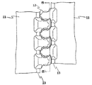
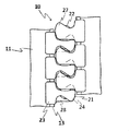
- FIG. 1 shows a state in which the magnetic elements 12 of the magnetic fastener 10 according to the present embodiment are separated
- FIG. 3 shows a state in which the magnetic elements 12 are connected.
- the magnetic fastener 10 according to the present embodiment includes a pair of left and right fastener tapes 11 and a plurality of magnetic tapes arranged at predetermined intervals along the tape longitudinal direction at opposing tape side edges of the pair of left and right fastener tapes 11. And an element 12.
- Each of the fastener tapes 11 has a core string 13 having an enormous cross-sectional view extending in the vertical direction at each side edge, and the magnetic element 12 is injection-molded (insert molding) so as to sandwich the core string 13 from the front and back.
- the magnetic elements 12 have the same shape, and the left magnetic element 12 row and the right magnetic element 12 row are front-back.
- the magnetic element 12 is fixed across the front and back surfaces of the fastener tape 11, and a spherical body made of neodymium magnet embedded in the main body 21 with the polyacetal main body 21, the upper end 14a and the lower end 14b exposed.
- the magnetic body 22 is provided.
- the upper end portion 14a is a portion exposed from the main body portion 21 on the upper side in the tape longitudinal direction of the main body portion 21, and the lower end portion 14b is a portion exposed from the main body portion 21 on the lower side in the tape longitudinal direction of the main body portion 21.
- the exposed upper and lower end portions 14a and 14b are also referred to as tip portions.
- the magnetic bodies 22 are arranged in a straight line in the vertical direction, and the left and right magnetic elements 12 are magnetized on the opposite side between one adjacent magnetic element 12. Element 12 enters and connects.
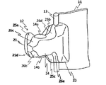
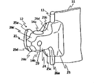
- FIGS. 6 and 7 show a state in which one of the magnetic elements 12 attached to the fastener tape 11 is viewed from the diagonally left front and from the front.
- FIGS. 8 and 9 show the magnetic element 12 as viewed from the diagonally rear left side and the true rear side, respectively.
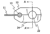
- 10 is a cross-sectional view taken along the line CC ′ of FIG. 9
- FIG. 11 is an excerpt of one of the magnetic elements taken from FIG. 2
- FIG. 12 is a cross-sectional view taken along the line AA ′ of FIG. Are shown respectively.
- the configuration of the magnetic element 12 will be described in detail with reference to FIGS.
- the N pole and the S pole are always arranged in the same direction in the vertical direction so that the magnetic elements 12 can be connected side by side in the vertical direction.
- the magnetic body 22 has both the top and bottom ends 14a and 14b exposed from the main body 21, and the degree of exposure is about the same up and down. From FIG. 11 and FIG. 12, regarding the cross-sectional area of the magnetic body 22 in the cross section orthogonal to the tape longitudinal direction, the magnetic body 22 is located inside the main body portion 21 rather than the diameter X that gives the maximum cross-sectional area at both exposed end portions 14 a and 14 b. It can be understood that the diameter Y giving the maximum cross-sectional area in the portion accommodated in the container is larger, and it is difficult to drop off vertically.
- the main body portion 21 includes a leg portion 23 for fixing the magnetic element 12 to the fastener tape 11 by sandwiching the core string 13 at the tape side edge portion from the front and back, and a leg portion 23 toward the tape side edge portion facing the main portion 21. It has a head 24 that protrudes from the vicinity of the center in the vertical direction and has a cavity extending in the vertical direction for accommodating the magnetic body 22.
- the opposing magnetic elements 12 can be connected up and down along the vertical direction of the tape by the magnetic force of the magnetic body 22, but the main body 21 has engaging convex portions and engaging concave portions for reinforcing the connection at various places.
- the front and back surfaces of the main body 21 are located above the tip of the head 24.
- first members that receive the first engaging protrusions 25a.
- a third engagement member 26a receives the third engagement protrusion 25c at the lower end of the head 24.
- the second engagement recess 26b receives the second engagement protrusion 25b.
- a mating recess 26 c is present at the upper end of the head 24, and a fourth engagement recess 26 d that receives the fourth engagement projection 25 d is present above the base of the head 24.
- the magnetic fastener 10 in a connected state is pushed up to the front and back.
- the resistance force to the force in the direction can be increased (see FIGS. 4 and 5).
- the left and right magnetic elements 12 can be smoothly engaged and disengaged.
- the first engaging convex portion 25a has a mountain shape protruding upward, when engaged with the first engaging concave portion 26a having a corresponding valley shape, the magnetic fastener 10 in a connected state is formed.
- the 1st engagement convex part 25a becomes a taper shape which tapers upwards, engagement and disengagement of the left and right magnetic elements 12 can be performed smoothly. Further, in the present embodiment, the magnetic poles of the magnetic element 12 can be confirmed by using the first engaging convex portions 25a having a mountain shape protruding only upward.
- the engaging convex portions (25 a, 25 b, 25 c, 25 d) are moved to the engaging concave portions by bringing the magnetic elements in the left and right separated state closer to each other from the state separated from the front and back sides (26a, 26b, 26c, 26d) are received and connected. Since the upper and lower surfaces of the magnetic body are spherical, the connection from the front and back directions is performed smoothly, and bending in the front and back directions is easy. Further, when the magnetic elements are connected, there is a gap between the main body portions 21 adjacent to each other in the vertical direction because the magnetic body 22 is exposed from the main body portion 21 up and down. Easy to connect from the direction and easy to bend.
- the shape of the magnetic body 22 is spherical.
- a cylindrical shape as shown in FIG. 13 may be used, and the upper and lower bases of the cylindrical shape as shown in FIG. It is also possible to form a capsule.
- it is necessary to pay attention to the direction of the embedded portion and the range of the exposed portion so that the cross-sectional area perpendicular to the longitudinal direction of the tape gradually decreases at the exposed tip portion.
- the cross-sectional area of the magnetic body in a cross section orthogonal to the tape longitudinal direction the maximum cross-sectional area in the portion where the magnetic body is accommodated in the main body is larger than the maximum cross-sectional area in both exposed end portions.
- the magnetic body should be embedded in the direction in which the exposed portion of the magnetic body becomes the side surface of the cylinder, and the capsule-like magnetic body as shown in FIG.
- the main body portion accommodates part of the curved surfaces of the upper and lower bottoms so that the side surfaces of the magnetic body are not exposed.
- the columnar magnetic body shown in FIG. 13 is housed in the main body 21 with the center axis of the column parallel to the left-right direction.
- the dimension of the magnetic body in the left-right direction is constant, the cross section perpendicular to the left-right direction is circular, and the cross-sectional area at the cross section perpendicular to the tape longitudinal direction is represented by a rectangular area at the front end.
- the cross-sectional area of the portion accommodated in the main body 21 is larger than the cross-sectional area. If it is this shape, it will be easy to be smoothly connected with respect to one magnetic element, when the other magnetic element is connected by making it mutually approach from the state spaced apart from the front and back.
- the center axis of the columnar magnetic body shown in FIG. 13 may be directed in the front-back direction.
- the first engaging convex portion 25a protrudes in the tape longitudinal direction from the magnetic body 22, so that it is difficult for the force to be applied to the magnetic body with respect to the force in the separating direction at the time of connection. That is, the dimension from the base point to the tip of the first engaging convex portion 25a is formed larger than the dimension from the base point to the tip of the magnetic body 22 with the center in the tape longitudinal direction of the magnetic element 12 as the base point.
- the first engagement convex portion 25a is located on the opposite fastener tape side (the front end side of the main body portion) from the center in the tape width direction of the magnetic body, and the first engagement convex portion 25a of the magnetic element of the opposite fastener tape.
- the first engaging recess 26a that engages with the magnetic material is located closer to the fastener tape side to which the magnetic body 22 is fixed, that is, the base side (leg side) of the head 24 than the center of the magnetic body in the tape width direction.
- FIG. 15 Another shape of the magnetic body 22 is shown in FIG. 15, and here, the shape is different between the N pole side and the S pole side.
- the magnetic body 22 has a shape in which a part of the exposed lower end of the sphere is cut in a direction perpendicular to the vertical direction, the N pole side is a spherical surface, and the S pole side is a flat surface.
- the magnetic pole is not determined in advance, and even after magnetizing after injection molding with the magnetic body embedded in the main body, depending on the type of magnet, for example, neodymium is an anisotropic magnet, Since the direction of magnetization is determined, the direction can be matched to the mold also in that case. Note that the magnet is isotropic with respect to anisotropy, and if it is isotropic, it is not necessary to match the direction of magnetization. In general, anisotropic magnets have a stronger magnetic force than isotropic magnets.
- the main body 21 receives the first engagement convex portion 25 a that protrudes upward in the shape of a mountain at the tip of the head 24, and the first engagement convex portion 25 a below the base of the head 24.
- the trough-shaped first engaging recess 26a is provided, it is not necessary to have such a shape, and it is possible to finish the same shape as other engaging projections and engaging recesses.
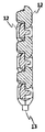
- FIG. 16 is a front view showing an example of such a magnetic fastener, in which each magnetic element is separated.
- FIG. 17 shows a state where the magnetic elements of FIG. 16 are connected. Also in this modification, each magnetic element 12 has the same shape.
- the main body portion 21 is provided with only one engaging convex portion and one engaging concave portion.
- the front and back surfaces of the main body 21 approach the tip of the head 24.
- On the other side of the front and back surfaces in FIGS. 17 and 18, the front surface of the row of the left elements 12 and the back surface of the row of the right elements 12) are engaging concave portions 28 that receive the engaging convex portions 27. 24 below the root.
- the engagement convex portion 27 and the engagement concave portion 28 are engaged with each other on the front and back sides, so that the magnetic fastener 10 in a connected state is separated in the left and right directions in addition to the resistance force to pull the magnetic fastener 10 in the direction to separate the front and back surfaces.
- the resistance to the pulling force can also be increased.
- the left and right magnetic elements 12 can be smoothly engaged and disengaged. Since the engagement convex portion 27 has a tapered shape that tapers upward, the left and right magnetic elements 12 can be smoothly engaged and disengaged.
- the magnetic poles of the magnetic element 12 can be confirmed by using the engaging convex portions 27 having a mountain shape protruding only upward.
- FIG. 16 and 17 since the dimension in the tape longitudinal direction of the head 24 of the main body 21 is larger than the same dimension of the magnetic body 22, when viewed from the surface shown in FIG. The magnetic body 22 does not protrude from the main body portion 21 in the tape longitudinal direction.
- at the time of connection in addition to being connected close to each other from the front and back directions, they can be connected close to each other from the left and right directions.
- a magnetic body in which the central axis of the columnar magnetic body shown in FIG. 13 faces the front and back directions can also be used.
- the fastener tape is rotated with respect to the longitudinal direction of the tape, and one fastener tape is rotated with respect to the other fastener tape so that one fastener tape is orthogonal to the other fastener tape. You can also.
- FIG. 10 A further variation is shown in FIG.
- circular recesses are formed on the front and back surfaces of the head 24 with respect to the magnetic element 12 according to the present embodiment.
- the depression 29 is formed corresponding to the formation of a convex portion on the mold in order to further stabilize the position of the magnetic body by pressing in the front and back directions in the mold during the injection molding of the magnetic element 12. It is what is done.
Landscapes
- Slide Fasteners (AREA)
Abstract
L'invention porte sur une fermeture à glissière magnétique, laquelle fermeture tolère une utilisation à long terme et est facile à produire. Il est fourni une fermeture à glissière magnétique (10) dans laquelle de multiples éléments magnétiques (12) sont alignés le long de la direction longitudinale sur les bords latéraux d'une paire de bandes de fermeture à glissière se faisant face (11), et les éléments se faisant face sont reliés les uns aux autres par magnétisme, dans laquelle fermeture : chaque élément magnétique (12) comporte un corps principal (21) constitué par une résine synthétique et un corps magnétique (22) incorporé dans le corps principal (21) ; les deux extrémités (14a, 14b) du corps magnétique (22) dans la direction longitudinale de la bande sont toutes deux exposées à partir du corps principal (21) ; et les surfaces de section transversales des deux extrémités exposées (14), qui sont des sections transversales orthogonales à la direction longitudinale de la bande, diminuent graduellement à mesure que les extrémités s'éloignent à partir du corps principal (21) le long de la direction longitudinale de la bande.
Priority Applications (3)
| Application Number | Priority Date | Filing Date | Title |
|---|---|---|---|
| PCT/JP2011/063981 WO2012172693A1 (fr) | 2011-06-17 | 2011-06-17 | Fermeture à glissière magnétique |
| JP2013520397A JP5599944B2 (ja) | 2011-06-17 | 2011-06-17 | 磁性ファスナー |
| CN201180070910.1A CN103619207B (zh) | 2011-06-17 | 2011-06-17 | 磁性拉链 |
Applications Claiming Priority (1)
| Application Number | Priority Date | Filing Date | Title |
|---|---|---|---|
| PCT/JP2011/063981 WO2012172693A1 (fr) | 2011-06-17 | 2011-06-17 | Fermeture à glissière magnétique |
Publications (1)
| Publication Number | Publication Date |
|---|---|
| WO2012172693A1 true WO2012172693A1 (fr) | 2012-12-20 |
Family
ID=47356719
Family Applications (1)
| Application Number | Title | Priority Date | Filing Date |
|---|---|---|---|
| PCT/JP2011/063981 Ceased WO2012172693A1 (fr) | 2011-06-17 | 2011-06-17 | Fermeture à glissière magnétique |
Country Status (3)
| Country | Link |
|---|---|
| JP (1) | JP5599944B2 (fr) |
| CN (1) | CN103619207B (fr) |
| WO (1) | WO2012172693A1 (fr) |
Cited By (4)
| Publication number | Priority date | Publication date | Assignee | Title |
|---|---|---|---|---|
| IT201600130023A1 (it) * | 2016-12-22 | 2018-06-22 | Aiani Jacopo | Cerniera lampo con chiusura a profili accoppiabili |
| JP2019502493A (ja) * | 2016-01-23 | 2019-01-31 | フィドロック・ゲーエムベーハーFidlock Gmbh | 2つの部品を着脱自在に連結するクロージャ装置 |
| WO2020144487A1 (fr) * | 2019-01-10 | 2020-07-16 | Karoly Miklos Laszlo | Structure de fermeture à glissière magnétique, sans curseur |
| WO2024050609A1 (fr) * | 2022-09-10 | 2024-03-14 | Perry John Underwood | Système de fixation |
Families Citing this family (5)
| Publication number | Priority date | Publication date | Assignee | Title |
|---|---|---|---|---|
| CN109463850B (zh) * | 2018-10-17 | 2021-06-25 | 福建浔兴拉链科技股份有限公司 | 一种多面牙拉链 |
| CN109875145A (zh) * | 2019-03-30 | 2019-06-14 | 彭青珍 | 一种贴片式雨衣 |
| CN111869998A (zh) * | 2020-08-13 | 2020-11-03 | 安徽信息工程学院 | 一种防护性的拉链结构 |
| US12207710B2 (en) * | 2020-12-24 | 2025-01-28 | Ykk Corporation | Fastener stringer, slide fastener, and method for producing stopper component and slide fastener |
| CN117179426A (zh) * | 2023-10-11 | 2023-12-08 | 江苏盛业拉链科技有限公司 | 一种拉链牙及拉链结构 |
Citations (5)
| Publication number | Priority date | Publication date | Assignee | Title |
|---|---|---|---|---|
| JPS60261404A (ja) * | 1984-06-11 | 1985-12-24 | 中松 義郎 | マグネツトフアスナ |
| JPH0464209U (fr) * | 1990-10-17 | 1992-06-02 | ||
| JP2006149824A (ja) * | 2004-11-30 | 2006-06-15 | Ykk Corp | ファスナー |
| JP2007319253A (ja) * | 2006-05-30 | 2007-12-13 | Ykk Corp | ファスナー |
| WO2010100744A1 (fr) * | 2009-03-05 | 2010-09-10 | Ykk株式会社 | Chaîne de fermeture et fermeture |
-
2011
- 2011-06-17 JP JP2013520397A patent/JP5599944B2/ja active Active
- 2011-06-17 WO PCT/JP2011/063981 patent/WO2012172693A1/fr not_active Ceased
- 2011-06-17 CN CN201180070910.1A patent/CN103619207B/zh active Active
Patent Citations (5)
| Publication number | Priority date | Publication date | Assignee | Title |
|---|---|---|---|---|
| JPS60261404A (ja) * | 1984-06-11 | 1985-12-24 | 中松 義郎 | マグネツトフアスナ |
| JPH0464209U (fr) * | 1990-10-17 | 1992-06-02 | ||
| JP2006149824A (ja) * | 2004-11-30 | 2006-06-15 | Ykk Corp | ファスナー |
| JP2007319253A (ja) * | 2006-05-30 | 2007-12-13 | Ykk Corp | ファスナー |
| WO2010100744A1 (fr) * | 2009-03-05 | 2010-09-10 | Ykk株式会社 | Chaîne de fermeture et fermeture |
Cited By (6)
| Publication number | Priority date | Publication date | Assignee | Title |
|---|---|---|---|---|
| JP2019502493A (ja) * | 2016-01-23 | 2019-01-31 | フィドロック・ゲーエムベーハーFidlock Gmbh | 2つの部品を着脱自在に連結するクロージャ装置 |
| US11083251B2 (en) | 2016-01-23 | 2021-08-10 | Fidlock Gmbh | Closure device for detachably connecting two parts |
| IT201600130023A1 (it) * | 2016-12-22 | 2018-06-22 | Aiani Jacopo | Cerniera lampo con chiusura a profili accoppiabili |
| WO2018116033A1 (fr) * | 2016-12-22 | 2018-06-28 | AIANI, Jacopo | Fermeture à glissière pourvue d'une fermeture à profils couplables |
| WO2020144487A1 (fr) * | 2019-01-10 | 2020-07-16 | Karoly Miklos Laszlo | Structure de fermeture à glissière magnétique, sans curseur |
| WO2024050609A1 (fr) * | 2022-09-10 | 2024-03-14 | Perry John Underwood | Système de fixation |
Also Published As
| Publication number | Publication date |
|---|---|
| JPWO2012172693A1 (ja) | 2015-02-23 |
| JP5599944B2 (ja) | 2014-10-01 |
| CN103619207B (zh) | 2015-11-25 |
| CN103619207A (zh) | 2014-03-05 |
Similar Documents
| Publication | Publication Date | Title |
|---|---|---|
| JP5599944B2 (ja) | 磁性ファスナー | |
| US7320158B2 (en) | Fastener | |
| JP4610521B2 (ja) | ファスナー | |
| KR101835175B1 (ko) | 자기-정렬 지퍼 | |
| US20040244419A1 (en) | Connector for accessories | |
| JP6513675B2 (ja) | フックを有する保持デバイス、それを備える組立体、及び、前記保持デバイスを成形によって製作する方法 | |
| KR101703816B1 (ko) | 슬라이드 파스너 | |
| US5199138A (en) | Magnetic fastener | |
| US8544705B2 (en) | Multi-functional belt buckle | |
| CN102711536A (zh) | 磁锁、磁钥匙及其组合 | |
| US20100022158A1 (en) | Magnet And Pin for Block Toy | |
| EP0590206A1 (fr) | Fermoir | |
| US20130212841A1 (en) | Replacement zipper pull | |
| TWI361052B (en) | Autolock slide for slide fastener | |
| WO2019186665A1 (fr) | Boucle | |
| CN103476465A (zh) | 高尔夫球杆头套 | |
| US20060084300A1 (en) | Magnetic construction kit adapted for use with construction blocks | |
| CN106880133B (zh) | 拉链用拉头 | |
| CN102894555B (zh) | 拉链用分离嵌插件及拉链 | |
| CN110580996B (zh) | 电磁线圈 | |
| KR101623473B1 (ko) | 인서트 사출 금형 결합용 마그넷 | |
| TWM347985U (en) | Downward-pulling fast releasing extender | |
| TWM483188U (zh) | 磁扣式圖釘 | |
| JP5568256B2 (ja) | アクセサリ用クラスプ | |
| JPH02187004A (ja) | 係合具 |
Legal Events
| Date | Code | Title | Description |
|---|---|---|---|
| 121 | Ep: the epo has been informed by wipo that ep was designated in this application |
Ref document number: 11867736 Country of ref document: EP Kind code of ref document: A1 |
|
| ENP | Entry into the national phase |
Ref document number: 2013520397 Country of ref document: JP Kind code of ref document: A |
|
| NENP | Non-entry into the national phase |
Ref country code: DE |
|
| 122 | Ep: pct application non-entry in european phase |
Ref document number: 11867736 Country of ref document: EP Kind code of ref document: A1 |