WO2012172767A1 - Sensitomètre spectral, procédé sensitométrique spectral - Google Patents
Sensitomètre spectral, procédé sensitométrique spectral Download PDFInfo
- Publication number
- WO2012172767A1 WO2012172767A1 PCT/JP2012/003766 JP2012003766W WO2012172767A1 WO 2012172767 A1 WO2012172767 A1 WO 2012172767A1 JP 2012003766 W JP2012003766 W JP 2012003766W WO 2012172767 A1 WO2012172767 A1 WO 2012172767A1
- Authority
- WO
- WIPO (PCT)
- Prior art keywords
- spectral sensitivity
- short
- circuit current
- light
- measured
- Prior art date
- Legal status (The legal status is an assumption and is not a legal conclusion. Google has not performed a legal analysis and makes no representation as to the accuracy of the status listed.)
- Ceased
Links
Images


Classifications
-
- H—ELECTRICITY
- H02—GENERATION; CONVERSION OR DISTRIBUTION OF ELECTRIC POWER
- H02S—GENERATION OF ELECTRIC POWER BY CONVERSION OF INFRARED RADIATION, VISIBLE LIGHT OR ULTRAVIOLET LIGHT, e.g. USING PHOTOVOLTAIC [PV] MODULES
- H02S50/00—Monitoring or testing of PV systems, e.g. load balancing or fault identification
- H02S50/10—Testing of PV devices, e.g. of PV modules or single PV cells
-
- Y—GENERAL TAGGING OF NEW TECHNOLOGICAL DEVELOPMENTS; GENERAL TAGGING OF CROSS-SECTIONAL TECHNOLOGIES SPANNING OVER SEVERAL SECTIONS OF THE IPC; TECHNICAL SUBJECTS COVERED BY FORMER USPC CROSS-REFERENCE ART COLLECTIONS [XRACs] AND DIGESTS
- Y02—TECHNOLOGIES OR APPLICATIONS FOR MITIGATION OR ADAPTATION AGAINST CLIMATE CHANGE
- Y02E—REDUCTION OF GREENHOUSE GAS [GHG] EMISSIONS, RELATED TO ENERGY GENERATION, TRANSMISSION OR DISTRIBUTION
- Y02E10/00—Energy generation through renewable energy sources
- Y02E10/50—Photovoltaic [PV] energy
Definitions
- the present invention relates to an apparatus and a method for determining the spectral sensitivity of a solar cell.
- FIG. 2 shows the spectral irradiance E ( ⁇ ) of the reference sunlight, which is shown in IEC60904.
- FIG. 3 shows an example of the spectral irradiance L ( ⁇ ) of the solar simulator.
- the horizontal axis indicates the wavelength expressed in nm
- the vertical axis indicates the illuminance expressed in ⁇ W / cm 2 / nm
- the horizontal axis indicates the wavelength expressed in nm
- the vertical axis indicates the illuminance expressed in ⁇ W / cm 2 / nm.
- the measurer uses the returned sample as the company's reference cell for light adjustment of the solar simulator. That is, the measurer irradiates the reference cell with the irradiation light of the solar simulator, and adjusts the light amount of the solar simulator so that the short circuit current I becomes the measurement value A. And the characteristic of the solar cell (of the product to be inspected) to be actually measured is measured. Although it is difficult to accurately reproduce the spectrum of the reference sunlight as described above, this is a technique for adjusting the solar simulators of various companies to the extent possible.
- the measurer when the solar simulator is calibrated using the reference cell, the measurer creates a sample in advance and sends it to a public institution such as the National Institute of Advanced Industrial Science and Technology. Need to receive a measured short circuit current measurement and sample. This is time consuming, time consuming and expensive.
- the solar simulator need not be calibrated only once, but each time the spectral sensitivity of the solar cell to be measured changes, a new reference cell must be created and calibrated again. Therefore, the time and cost required for calibration of the solar simulator are enormous.
- Non-Patent Document 1 when adjusting the light amount of the solar simulator, in order to price the short-circuit current due to the light of the standard test condition of the reference cell, that is, as a method of calculating the short-circuit current ISTC due to the light of the standard test condition of the solar cell, A method has been proposed (see Non-Patent Document 1).
- S (I) ⁇ S (I, ⁇ ) obtained from the spectral sensitivity (differential spectral response) S (I, ⁇ ) of the solar cell and the spectral irradiance E AM1.5 ⁇ ( ⁇ ) of the standard test conditions of the reference cell ⁇ ) ⁇ ⁇ E AM1.5 ⁇ ( ⁇ ) d ⁇ / ⁇ E AM1.5 ⁇ ( ⁇ ′) d ⁇ ′ ⁇ is used, and I STC satisfying the following formula A is the light of the standard test condition of the solar cell. Due to the short circuit current.
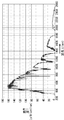
- FIG. 4 in the solar cell, as the irradiation intensity applied to the solar cell increases and the short-circuit current increases, the spectral sensitivity of the long wavelength increases.
- the graph indicated by reference symbol F0 is a graph schematically showing FIG. 4, and the graphs indicated by reference symbols F1, F2, F3, etc. are graphs showing the spectral sensitivities for each irradiation intensity in FIG.
- the horizontal axis indicates the wavelength expressed in nm
- the vertical axis indicates the conversion efficiency expressed in A / W.
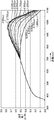
- the graph indicating the relationship between the irradiation intensity and the short circuit current is a straight line.
- the graph showing the relationship between the irradiation intensity and the short-circuit current is a curve graph as indicated by the reference symbol Fa. become.
- the sensitivity on the long wavelength side increases and the value of ⁇ I / ⁇ E increases.
- the spectral sensitivity S (I i , ⁇ ) is measured by sequentially applying different monochromatic lights (actually, having a narrow wavelength band of several nanometers) while irradiating the bias light whose short-circuit current I i is measured. Light of a wavelength), and the current from the solar cell is sequentially obtained.
- the spectral sensitivity S (I i , ⁇ ) needs to be obtained in a predetermined wide wavelength range according to the characteristics of the solar cell. For example, CIS type solar cells have photosensitivity in the range of 300 nm to 1300 nm.
- the bias light is stable. Need to be.
- the present invention has been made in view of the above circumstances, and even if the short-circuit current fluctuates without the bias light being stabilized while measuring the spectral sensitivity, the spectral sensitivity at the desired short-circuit current I i is
- An object of the present invention is to provide a spectral sensitivity measuring apparatus and method capable of obtaining S (I i , ⁇ ).
- the spectral sensitivity measuring apparatus includes a light source unit capable of individually irradiating a solar cell to be measured with a plurality of irradiation lights having different light amounts superimposed on light of a narrow wavelength band,
- the measurement unit that measures the short-circuit current and spectral sensitivity of the solar cell when receiving any one of the irradiation lights, and the measurement when sequentially irradiating the plurality of irradiation lights individually
- the spectral sensitivity of the predetermined narrow wavelength band when the desired short-circuit current is measured is calculated based on the respective short-circuit currents measured in the unit and the spectral sensitivity when the short-circuit current is measured.
- a spectral sensitivity calculation unit Therefore, such a spectral sensitivity measuring apparatus can obtain the spectral sensitivity at a desired short-circuit current even if the short-circuit current fluctuates because the irradiation light is not stabilized while measuring the spectral sensitivity.
- the spectral sensitivity measuring apparatus obtains the spectral sensitivity S (I i , ⁇ ) used when calculating the above (formula A) in consideration of the temporal variation of the bias light during the spectral sensitivity measurement. Is. That is, even if the bias light is not actually stable, the spectral sensitivity S (I i , ⁇ ) measured when the bias light is stable can be obtained.
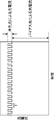
- FIG. 1 is a block diagram showing the configuration of the spectral sensitivity measuring apparatus 100.
- This spectral sensitivity measuring apparatus 100 irradiates monochromatic light (actually, light having a wavelength having a narrow wavelength band of several nm) while irradiating with bias light, and sequentially obtains the current from the solar cell 11. Is used to calculate the spectral sensitivity of the solar cell 11 with light of E AM1.5 ⁇ ( ⁇ ).
- the spectral sensitivity measuring apparatus 100 includes a light source 2, a spectral light source drive control unit 1, an optical system 3a, an optical system 3b, an optical system 3c, an optical system 3d, a monochromator 4, and a monochromator control unit.
- a light source 2 a spectral light source drive control unit 1
- an optical system 3a an optical system 3b
- an optical system 3c an optical system 3d
- a monochromator 4 and a monochromator control unit.
- a DC amplifier 13, a DC amplifier 14, a calculation control unit 15, a data input / output unit 16, a data storage unit 17, a setting unit 18, and a display unit 19 are provided.
- the light source 2 is a xenon lamp or the like that irradiates light to the solar cell 11, and the spectral light source drive control unit 1 is a device that controls the intensity of the output light of the light source 2.
- the optical system 3a, the optical system 3b, the optical system 3c, and the optical system 3d are optical elements such as a lens for condensing or collimating (collimating) light according to the application.
- the monochromator 4 is a spectroscope that spatially disperses light in a wide range of wavelengths and extracts only a narrow range of wavelengths with a slit or the like.
- the monochromator 4 includes, for example, an entrance slit, a first reflecting mirror, a diffraction grating, a second reflecting mirror, and an exit slit, and diffracts an incident light beam incident through the entrance slit by the first reflecting mirror.
- the apparatus reflects the diffracted light of the incident light beam reflected to the grating and diffracted by the diffraction grating to the exit slit by the second reflecting mirror.
- the monochromator control unit 5 is a functional unit that controls the monochromator 4 so as to extract the wavelength in the desired range.
- the optical blade 6a is a disk-like member in which notches extending in the radial direction with a predetermined width are arranged at regular intervals in the circumferential direction, and the servo motor 6 rotates the optical blade 6a around its center in a servo mechanism.
- the chopping motor drive control unit 7 is a device that controls the servo motor 6 so that the optical blade 6a rotates at a desired speed in order to generate pulsed light having a predetermined period T.
- the half mirror 20 and the half mirror 21 are optical elements that reflect a part of incident light and transmit a part thereof, and are optical elements that distribute incident light into two.
- the light source 9 is a xenon lamp or the like that irradiates light to the solar cell 11, and the bias light source drive control unit 8 is a device that controls the intensity of the output light of the light source 9.
- the irradiance measurement unit 10 is a device that measures the irradiance of light reflected by the half mirror 20 (monochromatic light emitted from the monochromator 4), and the DC amplifier 14 is measured by the irradiance measurement unit 10.
- the irradiance ⁇ E indicated by 5 is output.
- the solar cell 11 is a solar cell to be measured.
- the light emitted from the light source 2 is incident on the monochromator 4 through the optical system 3a, and light of a predetermined wavelength is cut out by the monochromator 4, and monochromatic light is emitted from the monochromator 4.
- the monochromatic light emitted from the monochromator 4 enters the half mirror 20 via the optical system 3b, and a part of the incident monochromatic light is reflected and enters the irradiance measurement unit 10.
- the remaining monochromatic light is transmitted and enters the optical blade 6a.
- the monochromatic light incident on the optical blade 6a is transmitted or shielded by notches arranged in the circumferential direction of the optical blade 6a rotating by the servo motor 6, thereby being turned ON / OFF at a predetermined period T to be pulsed. It enters the solar cell 11 via the half mirror 21 via 3c.
- the light emitted from the light source 9 enters the half mirror 21 via the optical system 3d, and the bias light reflected by the half mirror 21 enters the solar cell 11. That is, the bias light emitted from the light source 9 is superimposed on the monochromatic light pulse emitted from the monochromator 4 and enters the solar cell 11.
- FIG. 6 is a diagram illustrating an example of a graph of the photocurrent output from the solar cell 11.
- the solar cell 11 includes light (bias light) emitted from the light source 9 and monochromatic light (monochromatic light pulse, modulation) that is turned on / off at a predetermined period (period T) by the optical blade 6a. Light) is superimposed. Therefore, as shown in this graph, the photocurrent output from the solar cell 11 includes a photocurrent caused by bias light and a photocurrent caused by a monochromatic light pulse incident at a predetermined period T.
- the lock-in amplifier 12 detects the photocurrent generated by the monochromatic light pulse shown in FIG. 6 by synchronizing with the predetermined period T, and ⁇ I shown in FIG. 5, that is, the change ⁇ I of the short-circuit current when the irradiation intensity changes ⁇ E. Output. Further, the DC amplifier 13 outputs the photocurrent due to the bias light shown in FIG. 4, that is, the value of the short-circuit current of the solar cell 11 indicated by the vertical axis of the graph of the reference symbol Fa shown in FIG.
- the arithmetic control unit 15 calculates EAM1.5 ⁇ ( ⁇ ) of the solar cell 11 from ⁇ I acquired from the lock-in amplifier 12, ⁇ E acquired from the DC amplifier 14, and the short-circuit current I acquired from the DC amplifier 13.
- the spectral sensitivity of the solar cell 11 by light is calculated, and the spectral light source drive controller 1 and the like are controlled to control the entire spectral sensitivity measuring apparatus 100.
- a method for calculating spectral sensitivity will be described in the section ⁇ Method for calculating spectral sensitivity>.
- the data input / output unit 16 is a so-called external interface such as a USB (Universal Serial Bus) port for exchanging data with an external device
- the data storage unit 17 may be, for example, a RAM (Random It consists of volatile storage elements such as Access Memory (ROM), non-volatile storage elements such as ROM (Read Only Memory) and rewritable EEPROM (Electrically Erasable Programmable Read Only Memory), hard disk, etc., and the operation control unit 15 operates. It stores the programs and data necessary to do it.
- the setting unit 18 is a device that inputs various data such as a command for starting the spectral sensitivity measurement process and parameters for the control unit such as the spectral light source drive control unit 1 necessary for the processing to the spectral sensitivity measurement apparatus 100. is there. For example, a keyboard or a mouse.
- the display unit 19 is a device that outputs (presents) the command and data input from the setting unit 18 and the spectral sensitivity value calculated by the calculation control unit 15.
- a display device such as a CRT (Cathode Ray Tube) display, an LCD (Liquid Crystal Display), an organic EL (Electro-Luminescence) display, a plasma display, or a printing device such as a printer.
- the calculation control unit 15, the data input / output unit 16, the data storage unit 17, the setting unit 18, the display unit 19, and the like of the spectral sensitivity measuring apparatus 100 are configured by a computer including a microprocessor, a memory, and its peripheral circuits, for example.
- the microprocessor is a so-called CPU (Central Processing Unit) or the like, and by executing a program stored in the memory, the spectral sensitivity measuring apparatus 100 functionally includes the arithmetic control unit 15 to the display unit 19 and the like. To prepare.
- CPU Central Processing Unit
- I ij fluctuates.
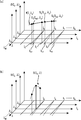
- the spectral sensitivity measuring apparatus 100 estimates a value S (I i , ⁇ j ) at a desired short-circuit current I i from the series of measured spectral sensitivities S t (I ij , ⁇ j ).
- the spectral sensitivity S (I i , ⁇ ) of the short-circuit current I i in that wavelength range Can be requested.
- the spectral sensitivity measuring apparatus 100 has a plurality of different short-circuit currents I ij at a certain wavelength ⁇ i and spectral sensitivity St (I ij , ⁇ j when each short-circuit current I ij is measured.
- FIG. 7A is a graph in which the wavelength ⁇ j , the short-circuit current I i, and the spectral sensitivity S (I i , ⁇ j ) are assigned to the axes orthogonal to each other.
- the spectral sensitivity measuring apparatus 100 scans a desired wavelength range while changing the wavelength (predetermined narrow wavelength band) from the wavelength ⁇ 0 to ⁇ M , and sequentially measures the spectral sensitivity.
- FIG. 7B is a diagram showing the spectral sensitivity S (I 0 , ⁇ ) when the short-circuit current is I 0 . In the graph of FIG.
- the broken line indicating the short-circuit current I i indicates that the short-circuit current initially set fluctuates gradually as the spectral sensitivity is measured sequentially from the wavelength ⁇ 0 to ⁇ M without the bias light being stabilized.
- the solid line indicates the case where the initially set short-circuit current does not fluctuate.
- the spectral sensitivity when the short-circuit currents I 0 , I 1 , and I 2 at the wavelength ⁇ 2 are considered. It is assumed that the short-circuit current I 0 gradually changes to I 02 as indicated by a broken line while measuring the spectral sensitivity while changing the wavelength. Similarly, it is assumed that the short-circuit current I 1 is I 12 and the short-circuit current I 2 is I 22 .
- the respective spectral sensitivities at the short-circuit currents I 02 , I 12 , and I 22 are St (I 02 , ⁇ 2 ), St (I 12 , ⁇ 2 ), and St (I 22 , ⁇ 2 ).
- the spectral sensitivity measuring apparatus 100 includes (I 02 , St (I 02 , ⁇ 2 )), (I 12 , St (I 12 , ⁇ 2 )), (I 22 , St (I 22 , The interpolation polynomial f 2 (I, ⁇ 2 ) is obtained from ⁇ 2 )).
- the spectral sensitivity measuring apparatus 100 can obtain the spectral sensitivity S (I 0 , ⁇ 2 ) at the time of the short-circuit current I 0 from the interpolation polynomial f 2 (I 0 , ⁇ 2 ).
- the apparatus 100 can obtain the spectral sensitivity S (I i , ⁇ ) at a constant short-circuit current I i over a desired wavelength range.
- S (I i , ⁇ j ) is estimated.
- FIG. 8 is a flowchart showing the spectral sensitivity measurement process of the spectral sensitivity measuring apparatus 100.
- the spectral sensitivity at N + 1 short-circuit currents is measured in a desired wavelength range at M + 1 wavelengths (narrow wavelength width).
- the spectral sensitivity S (I, ⁇ ) at each of the N + 1 short-circuit currents is calculated (see FIG. 7A).
- control parameter value ⁇ 0 of the light source 9 is determined so that the irradiance E b of the bias light emitted from the light source 9 is substantially equal to the light E AM1.5 ⁇ ( ⁇ ) of the standard test condition.
- the obtained control parameter value ⁇ 0 is set in the bias light source drive controller 8.
- the control parameter of the light source 9 here is a parameter for controlling the light amount of the light source 9 such as current and voltage of the light source 9.
- the calculation control unit 15 controls the spectral light source drive control unit 1 and the bias light source drive control unit 8 to control the light source 2 and the light source. 9 starts light irradiation, and 0 (zero) is set to the index i of the short-circuit current I (step S10).
- step S15 the calculation control unit 15, the irradiance ⁇ E irradiance measurement unit 10 has measured (lambda j), obtained through the DC amplifier 14 (step S15), and the change in short-circuit current from the lock-in amplifier 12 [Delta] I ( ( ⁇ j ) is acquired (step S16).
- step S18 N
- the arithmetic control unit 15 adds 1 to j (step S19).
- step S18 Y
- the processing in steps S13 to S19 is performed. Is repeated. If the stability of the bias light emitted from the light source 9 is not good while the processes in steps S13 to S19 are repeated, I 0 j is not constant.
- the arithmetic control unit 15 repeats the processing from steps S23 to S25 until j becomes M or more (step S24: Y).
- E AM1.5 ⁇ ( ⁇ ) it is not limited to E AM1.5 ⁇ ( ⁇ ), and it is also possible to calculate a short-circuit current when an arbitrary spectral irradiance E ⁇ ( ⁇ ) is virtually irradiated to the solar cell. .
- a spectral sensitivity measuring device includes a light source unit capable of individually irradiating a solar cell to be measured with a plurality of irradiation lights having different light amounts superimposed on light of a narrow wavelength band, and the plurality
- the measurement unit that measures the short-circuit current and spectral sensitivity of the solar cell when receiving any one of the irradiation lights, and the measurement when sequentially irradiating the plurality of irradiation lights individually
- the spectral sensitivity of the predetermined narrow wavelength band when the desired short-circuit current is measured is calculated based on the respective short-circuit currents measured in the unit and the spectral sensitivity when the short-circuit current is measured.
- a spectral sensitivity calculation unit is calculated based on the respective short-circuit currents measured in the unit.
- the spectral sensitivity measuring apparatus scans the solar cell to be measured by changing the wavelength of light in a narrow wavelength band within a predetermined wavelength range, and superimposes the light on the narrow wavelength band.
- a light source unit capable of individually irradiating a plurality of bias lights having different light amounts, and a short-circuit current and spectral sensitivity of the solar cell when receiving any one of the plurality of bias lights
- a measurement unit that superimposes light in a narrow wavelength range of light in a narrow wavelength band in the scan, and individually irradiates bias light having different light amounts.
- Spectral sensitivity for calculating the spectral sensitivity of the predetermined narrow wavelength band when a desired short-circuit current is measured based on each measured short-circuit current and the spectral sensitivity when the short-circuit current is measured Calculation And a part.
- the spectral sensitivity calculation unit measures a desired short-circuit current using an interpolation formula based on the short-circuit current and spectral sensitivity measured by the measurement unit. Then, the spectral sensitivity of the predetermined narrow wavelength band is calculated.
- mode is the light source part which can irradiate the several solar light which each overlaps with the light of a narrow wavelength band, and each light quantity differs separately to the solar cell of measurement object
- a spectral sensitivity measuring method used in a spectral sensitivity measuring apparatus comprising: a measurement of measuring a short-circuit current and spectral sensitivity of the solar cell when receiving any one of the plurality of irradiation lights A desired short-circuit current based on each step, and each short-circuit current measured in the measurement step and the spectral sensitivity when the short-circuit current is measured when the plurality of irradiation lights are sequentially irradiated individually.
- a spectral sensitivity measurement method is a spectral sensitivity measurement method for a solar cell, wherein the solar cell to be measured is scanned by changing the wavelength of light in a narrow wavelength band within a predetermined wavelength range.
- An irradiation step of individually irradiating a plurality of bias lights having different light amounts superimposed on the light in the narrow wavelength band, and the sun when receiving any one of the plurality of bias lights A measurement step for measuring each short-circuit current and each spectral sensitivity of the battery, and superimposing light in one of the narrow wavelength ranges of the light in the narrow wavelength band in the scanning, and applying bias light having different light amounts.
- the desired short-circuit current was measured based on each short-circuit current measured in the measurement step and the spectral sensitivity when the short-circuit current was measured. And a spectral sensitivity calculating a spectral response of said predetermined narrow wavelength band when.
- the spectral sensitivity measuring apparatus and the spectral sensitivity measuring method having such a configuration, when light of a predetermined narrow wavelength band is superimposed and a plurality of irradiation lights (bias lights) having different amounts of light are individually applied to the solar cell, Calculate the spectral sensitivity of the desired short-circuit current based on each measured short-circuit current and its spectral sensitivity, so calculate the spectral sensitivity even when the desired short-circuit current is not measured Is possible. Therefore, even if the short-circuit current fluctuates because the bias light is not stabilized while measuring the spectral sensitivity, the spectral sensitivity at the desired short-circuit current can be obtained.
- Spectral sensitivity measurement device calculates spectral sensitivity S (I i , ⁇ ) at desired short-circuit current I i even if the short-circuit current fluctuates because the bias light is not stable while measuring the spectral sensitivity. Is possible.
- the present invention is capable of obtaining a spectral sensitivity S (I i , ⁇ ) at a desired short-circuit current I i even if the short-circuit current fluctuates because the bias light is not stabilized while measuring the spectral sensitivity.
- a sensitivity measuring apparatus and method can be provided.
Landscapes
- Photovoltaic Devices (AREA)
- Investigating Or Analysing Materials By Optical Means (AREA)
- Photometry And Measurement Of Optical Pulse Characteristics (AREA)
- Testing Of Optical Devices Or Fibers (AREA)
Abstract
Lorsqu'il reçoit un rayon parmi de multiples rayons de lumière d'intensités différentes qui ont été superposés sur une étroite bande de longueurs d'ondes de lumière, le sensitomètre spectral d'après la présente invention mesure un courant de court-circuit et une sensibilité spectrale d'une cellule solaire. Ledit sensitomètre spectral comprend une unité de calcul de sensibilité spectrale qui, lorsqu'un courant de court-circuit souhaité a été mesuré, calcule la sensibilité spectrale au niveau de l'étroite bande de longueurs d'ondes prédéfinie sur la base des courants de court-circuit respectifs et des sensibilités spectrales associées aux courants de court-circuit mesurés qui sont mesurées au moyen d'une unité de mesure quand les multiples rayons de lumière sont diffusés individuellement et séquentiellement. Le sensitomètre spectral d'après la présente invention peut donc obtenir la sensibilité spectrale au niveau d'un quelconque courant de court-circuit souhaité, même en cas de fluctuation du courant de court-circuit à cause d'une instabilité de la lumière diffusée pendant la mesure de la sensibilité spectrale.
Priority Applications (1)
| Application Number | Priority Date | Filing Date | Title |
|---|---|---|---|
| JP2013520426A JP5761343B2 (ja) | 2011-06-14 | 2012-06-08 | 分光感度測定装置、および、分光感度測定方法 |
Applications Claiming Priority (2)
| Application Number | Priority Date | Filing Date | Title |
|---|---|---|---|
| JP2011131955 | 2011-06-14 | ||
| JP2011-131955 | 2011-06-14 |
Publications (1)
| Publication Number | Publication Date |
|---|---|
| WO2012172767A1 true WO2012172767A1 (fr) | 2012-12-20 |
Family
ID=47356774
Family Applications (1)
| Application Number | Title | Priority Date | Filing Date |
|---|---|---|---|
| PCT/JP2012/003766 Ceased WO2012172767A1 (fr) | 2011-06-14 | 2012-06-08 | Sensitomètre spectral, procédé sensitométrique spectral |
Country Status (2)
| Country | Link |
|---|---|
| JP (1) | JP5761343B2 (fr) |
| WO (1) | WO2012172767A1 (fr) |
Cited By (3)
| Publication number | Priority date | Publication date | Assignee | Title |
|---|---|---|---|---|
| CN103746654A (zh) * | 2014-02-14 | 2014-04-23 | 苏州众显电子科技有限公司 | 一种带便携光源的功率表测试高倍聚光电池片装置 |
| CN103762942A (zh) * | 2014-02-11 | 2014-04-30 | 苏州众显电子科技有限公司 | 一种快速简易功率表测试高倍聚光电池片装置 |
| JP2016144253A (ja) * | 2015-01-30 | 2016-08-08 | コニカミノルタ株式会社 | 分光感度測定装置 |
Families Citing this family (1)
| Publication number | Priority date | Publication date | Assignee | Title |
|---|---|---|---|---|
| CN102461025B (zh) | 2009-06-30 | 2014-10-22 | 汤姆森特许公司 | 重传数字信号的方法 |
Citations (3)
| Publication number | Priority date | Publication date | Assignee | Title |
|---|---|---|---|---|
| JPS6384078A (ja) * | 1986-09-26 | 1988-04-14 | Sharp Corp | 太陽電池の分光感度測定法 |
| JP2004281706A (ja) * | 2003-03-14 | 2004-10-07 | Japan Science & Technology Agency | Ledを用いた太陽電池の評価方法及びその評価装置 |
| WO2010058649A1 (fr) * | 2008-11-19 | 2010-05-27 | コニカミノルタセンシング株式会社 | Dispositif d'évaluation de batterie solaire et procédé d'évaluation de batterie solaire |
-
2012
- 2012-06-08 WO PCT/JP2012/003766 patent/WO2012172767A1/fr not_active Ceased
- 2012-06-08 JP JP2013520426A patent/JP5761343B2/ja not_active Expired - Fee Related
Patent Citations (3)
| Publication number | Priority date | Publication date | Assignee | Title |
|---|---|---|---|---|
| JPS6384078A (ja) * | 1986-09-26 | 1988-04-14 | Sharp Corp | 太陽電池の分光感度測定法 |
| JP2004281706A (ja) * | 2003-03-14 | 2004-10-07 | Japan Science & Technology Agency | Ledを用いた太陽電池の評価方法及びその評価装置 |
| WO2010058649A1 (fr) * | 2008-11-19 | 2010-05-27 | コニカミノルタセンシング株式会社 | Dispositif d'évaluation de batterie solaire et procédé d'évaluation de batterie solaire |
Cited By (3)
| Publication number | Priority date | Publication date | Assignee | Title |
|---|---|---|---|---|
| CN103762942A (zh) * | 2014-02-11 | 2014-04-30 | 苏州众显电子科技有限公司 | 一种快速简易功率表测试高倍聚光电池片装置 |
| CN103746654A (zh) * | 2014-02-14 | 2014-04-23 | 苏州众显电子科技有限公司 | 一种带便携光源的功率表测试高倍聚光电池片装置 |
| JP2016144253A (ja) * | 2015-01-30 | 2016-08-08 | コニカミノルタ株式会社 | 分光感度測定装置 |
Also Published As
| Publication number | Publication date |
|---|---|
| JPWO2012172767A1 (ja) | 2015-02-23 |
| JP5761343B2 (ja) | 2015-08-12 |
Similar Documents
| Publication | Publication Date | Title |
|---|---|---|
| JP4944231B2 (ja) | 太陽電池評価装置およびそれに用いられる光源評価装置 | |
| JP5223928B2 (ja) | 太陽電池評価装置および太陽電池評価方法 | |
| JP5761343B2 (ja) | 分光感度測定装置、および、分光感度測定方法 | |
| EP2790228A1 (fr) | Dispositif de mesure de réponse spectrale de cellule solaire | |
| JP2013156132A (ja) | 太陽電池評価装置および該方法 | |
| JP5626363B2 (ja) | 分光放射照度測定装置、分光放射照度測定システムおよび分光放射照度校正方法 | |
| JP4944233B2 (ja) | 太陽電池評価装置およびそれに用いられる光源評価装置 | |
| JP5696595B2 (ja) | 短絡電流測定装置、太陽電池評価装置、短絡電流測定方法、および、太陽電池評価方法 | |
| JP2005011958A (ja) | 光電変換素子の電流電圧特性の測定方法及び測定装置 | |
| JP5741774B1 (ja) | 太陽電池絶対分光感度測定装置および該方法 | |
| Garcia et al. | On the spectral response measurement of multijunction solar cells | |
| JP5900137B2 (ja) | 太陽電池評価装置および該方法 | |
| JP5772972B2 (ja) | 太陽電池評価装置、および太陽電池評価方法 | |
| JP5742835B2 (ja) | 太陽電池評価装置および太陽電池評価方法 | |
| JP5601308B2 (ja) | 太陽電池評価装置、及び、太陽電池評価方法 | |
| JP6447184B2 (ja) | 分光感度測定装置 | |
| JP5895691B2 (ja) | 太陽電池評価装置および該方法 | |
| Mahmoud et al. | New facility for primary calibration of differential spectral responsivity of solar cells using LDLS-based monochromatic source | |
| JP6464939B2 (ja) | 分光感度測定装置及び分光感度測定方法 | |
| JP2013234895A (ja) | 太陽電池評価装置および該方法 | |
| JP2013221857A (ja) | 太陽電池評価装置および該方法 | |
| Field | Methods and Instruments for the Characterization of Solar Cells | |
| Huang et al. | Comparison of two methods for short circuit current measurement of large size solar cell | |
| KR20230061699A (ko) | 페로브스카이트 태양전지의 양자효율 측정장치 및 그 제어방법 | |
| JP2012114375A (ja) | 太陽電池評価装置および評価方法 |
Legal Events
| Date | Code | Title | Description |
|---|---|---|---|
| 121 | Ep: the epo has been informed by wipo that ep was designated in this application |
Ref document number: 12801032 Country of ref document: EP Kind code of ref document: A1 |
|
| ENP | Entry into the national phase |
Ref document number: 2013520426 Country of ref document: JP Kind code of ref document: A |
|
| NENP | Non-entry into the national phase |
Ref country code: DE |
|
| 122 | Ep: pct application non-entry in european phase |
Ref document number: 12801032 Country of ref document: EP Kind code of ref document: A1 |