WO2012172823A1 - Catalyseur d'électrode de pile à combustible et son procédé de production - Google Patents
Catalyseur d'électrode de pile à combustible et son procédé de production Download PDFInfo
- Publication number
- WO2012172823A1 WO2012172823A1 PCT/JP2012/050529 JP2012050529W WO2012172823A1 WO 2012172823 A1 WO2012172823 A1 WO 2012172823A1 JP 2012050529 W JP2012050529 W JP 2012050529W WO 2012172823 A1 WO2012172823 A1 WO 2012172823A1
- Authority
- WO
- WIPO (PCT)
- Prior art keywords
- catalyst
- group
- fuel cell
- electrode catalyst
- nitrogen
- Prior art date
- Legal status (The legal status is an assumption and is not a legal conclusion. Google has not performed a legal analysis and makes no representation as to the accuracy of the status listed.)
- Ceased
Links
Images








Classifications
-
- H—ELECTRICITY
- H01—ELECTRIC ELEMENTS
- H01M—PROCESSES OR MEANS, e.g. BATTERIES, FOR THE DIRECT CONVERSION OF CHEMICAL ENERGY INTO ELECTRICAL ENERGY
- H01M4/00—Electrodes
- H01M4/86—Inert electrodes with catalytic activity, e.g. for fuel cells
- H01M4/90—Selection of catalytic material
- H01M4/9091—Unsupported catalytic particles; loose particulate catalytic materials, e.g. in fluidised state
-
- H—ELECTRICITY
- H01—ELECTRIC ELEMENTS
- H01M—PROCESSES OR MEANS, e.g. BATTERIES, FOR THE DIRECT CONVERSION OF CHEMICAL ENERGY INTO ELECTRICAL ENERGY
- H01M4/00—Electrodes
- H01M4/86—Inert electrodes with catalytic activity, e.g. for fuel cells
- H01M4/88—Processes of manufacture
- H01M4/8825—Methods for deposition of the catalytic active composition
- H01M4/8828—Coating with slurry or ink
- H01M4/8832—Ink jet printing
-
- H—ELECTRICITY
- H01—ELECTRIC ELEMENTS
- H01M—PROCESSES OR MEANS, e.g. BATTERIES, FOR THE DIRECT CONVERSION OF CHEMICAL ENERGY INTO ELECTRICAL ENERGY
- H01M4/00—Electrodes
- H01M4/86—Inert electrodes with catalytic activity, e.g. for fuel cells
- H01M4/90—Selection of catalytic material
- H01M4/9041—Metals or alloys
-
- H—ELECTRICITY
- H01—ELECTRIC ELEMENTS
- H01M—PROCESSES OR MEANS, e.g. BATTERIES, FOR THE DIRECT CONVERSION OF CHEMICAL ENERGY INTO ELECTRICAL ENERGY
- H01M8/00—Fuel cells; Manufacture thereof
- H01M8/10—Fuel cells with solid electrolytes
- H01M2008/1095—Fuel cells with polymeric electrolytes
-
- Y—GENERAL TAGGING OF NEW TECHNOLOGICAL DEVELOPMENTS; GENERAL TAGGING OF CROSS-SECTIONAL TECHNOLOGIES SPANNING OVER SEVERAL SECTIONS OF THE IPC; TECHNICAL SUBJECTS COVERED BY FORMER USPC CROSS-REFERENCE ART COLLECTIONS [XRACs] AND DIGESTS
- Y02—TECHNOLOGIES OR APPLICATIONS FOR MITIGATION OR ADAPTATION AGAINST CLIMATE CHANGE
- Y02E—REDUCTION OF GREENHOUSE GAS [GHG] EMISSIONS, RELATED TO ENERGY GENERATION, TRANSMISSION OR DISTRIBUTION
- Y02E60/00—Enabling technologies; Technologies with a potential or indirect contribution to GHG emissions mitigation
- Y02E60/30—Hydrogen technology
- Y02E60/50—Fuel cells
Definitions
- the present invention relates to an electrode catalyst for a fuel cell and a method for producing the same, and more particularly to an electrode catalyst for a fuel cell containing a group 13 element and a transition metal and a method for producing the same.
- a polymer electrolyte fuel cell is a type of fuel in which a solid polymer electrolyte is sandwiched between an anode and a cathode, fuel is supplied to the anode, oxygen or air is supplied to the cathode, and oxygen is reduced at the cathode to extract electricity. It is a battery. Hydrogen or methanol is mainly used as the fuel.
- a layer containing a catalyst (hereinafter referred to as “for fuel cell”) is provided on the cathode (air electrode) surface or anode (fuel electrode) surface of the fuel cell. Also referred to as “catalyst layer”).
- a noble metal is generally used, and noble metals such as platinum and palladium which are stable at a high potential and have high activity among the noble metals have been mainly used.
- noble metals are expensive and have limited resources, development of alternative catalysts has been required.
- base metal substitute catalysts base metal carbides, base metal oxides, base metal carbonitrides, chalcogen compounds and carbon catalysts that do not use any precious metal have been reported (for example, see Patent Documents 1 to 4). These materials are cheaper and have abundant resources than noble metal materials such as platinum.
- Patent Document 3 and Patent Document 4 exhibit high oxygen reduction catalytic activity, but have a problem of low stability under fuel cell operation conditions.
- the Nb and Ti oxycarbonitrides described in Patent Document 5 and Patent Document 6 can effectively exhibit the above performance to some extent.
- Patent Document 5 and Patent Document 6 have higher performance than conventional noble metal substitute catalysts, but heat treatment at a high temperature of 1600 ° C. to 1800 ° C. is required in part of the production process. (For example, Patent Document 5 Example 1 or Patent Document 6 Example 1).
- Patent Document 7 reports a technique relating to the production of a carbon-containing titanium oxynitride containing carbon, nitrogen and oxygen.
- a method for producing a metal carbonitride oxide having a granular or fibrous shape that is highly useful as an electrode catalyst and its application only as a thin film for a solar collector and a photocatalyst are described as uses. Applications have not been disclosed or studied.
- the phenol resin is a thermosetting resin having a three-dimensional network structure, it is difficult to uniformly mix and react with the metal oxide.
- the thermal decomposition temperature of the phenol resin is 400 ° C. to 900 ° C., there is a problem that the carbonization reaction due to complete decomposition of the phenol resin hardly occurs at a temperature of 1000 ° C. or less.
- Patent Document 8 discloses a method for producing an electrode catalyst characterized by firing a mixed material of an oxide and a carbon material precursor, but an electrode catalyst having sufficient catalytic performance has not been obtained. .
- Patent Document 9 discloses a fuel cell electrode catalyst using a polynuclear complex such as cobalt.
- the raw material has high toxicity, is expensive, and does not have sufficient catalytic activity. there were.
- Patent Document 10 discloses a fuel cell catalyst of an alloy containing Al, Cu, a Group VIII element, and a La series element supported on carbon. However, carbon is not a constituent of the catalyst itself.
- Non-Patent Document 2 discloses a method for producing an electrode catalyst characterized by firing a mixed material of titanium alkoxide and a carbon material precursor, but in the production process, an organic substance containing nitrogen is used. No electrode catalyst having sufficient catalytic performance has been obtained.
- JP 2004-303664 A International Publication No. 07/072665 Pamphlet US Patent Application Publication No. 2004/0096728 JP 2005-19332 A International Publication No. 2009/031383 Pamphlet International Publication No. 2009/107518 Pamphlet JP 2009-23877 A JP 2009-255053 A JP 2008-258150 A JP 2003-187812 A International Publication No. 2009/119523
- the object of the present invention is to solve such problems in the prior art.
- an object of the present invention is to provide a fuel cell electrode catalyst having high catalytic activity, which serves as a precious metal substitute catalyst.
- An object of the present invention is to provide a fuel cell electrode catalyst having high durability, which is a precious metal substitute catalyst.
- Another object of the present invention is to provide a method for producing a fuel cell electrode catalyst capable of producing a fuel cell electrode catalyst having high catalytic activity at low cost.
- An object of the present invention is to provide a method for producing a fuel cell electrode catalyst capable of producing a fuel cell electrode catalyst having high durability at low cost.
- the present invention relates to the following (1) to (15), for example.
- At least M1 which is at least one element selected from Group 3 to 7 transition metal elements, M2 which is at least one element selected from iron group elements, M3 which is at least one element selected from Group 13 elements, carbon
- the electrode catalyst for fuel cells which is more than g.
- M1 is at least one element selected from the group consisting of titanium, zirconium, hafnium, niobium, and tantalum.
- M1 is at least one element selected from the group consisting of titanium, zirconium, hafnium, niobium and tantalum
- M2 is iron
- M3 is at least one type selected from the group consisting of boron, aluminum, gallium and indium.
- the (110) plane spacing calculated by XRD measurement is The electrode catalyst for a fuel cell according to any one of the above (1) to (8), which is smaller than the (110) plane spacing calculated by XRD measurement of a catalyst produced in the same manner as the catalyst without adding M3.
- Step 1 of mixing a nitrogen-containing organic compound and a solvent to obtain a catalyst precursor solution, Step 2 for removing the solvent from the catalyst precursor solution to obtain a solid residue, and Step 3 for obtaining an electrode catalyst by heat-treating the solid residue obtained in Step 2 at a temperature of 500 to 1200 ° C.
- the manufacturing method of the electrode catalyst for fuel cells containing this.
- the compound containing M1 is one or more selected from the group consisting of metal nitrate, metal organic acid salt, metal acid chloride, metal alkoxide, metal halide, metal perchlorate and metal hypochlorite
- the nitrogen-containing organic compound is an amino group, nitrile group, imide group, imine group, nitro group, amide group, azide group, aziridine group, azo group, isocyanate group, isothiocyanate group, oxime group, diazo group, and nitroso group.
- a membrane electrode assembly comprising a cathode, an anode, and an electrolyte membrane disposed between the cathode and the anode, wherein the cathode is the electrode according to (18).
- a polymer electrolyte fuel cell comprising the membrane electrode assembly according to (19).
- the fuel cell electrode catalyst of the present invention has higher catalytic activity than conventional noble metal substitute catalysts.
- the fuel cell electrode catalyst of the present invention has higher durability than conventional noble metal substitute catalysts.
- the fuel cell electrode catalyst of the present invention can be produced at low cost.
- an electrode catalyst for a fuel cell of the present invention it is easy to ensure the safety of the production process at low cost without performing a heat treatment (firing) process at a high temperature, and includes a group 13 element and a transition metal.
- a fuel cell electrode catalyst having high catalytic activity and high durability can be produced.
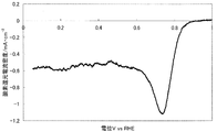
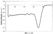
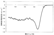
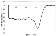
- FIG. 1 shows a current-potential curve obtained by evaluating the oxygen reducing ability of the fuel cell electrode (1-1) of Example 1-1.
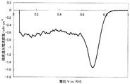
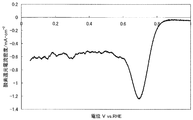
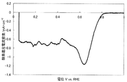
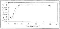
- FIG. 2 shows a current-potential curve obtained by evaluating the oxygen reducing ability of the fuel cell electrode (1-2) of Example 1-2.
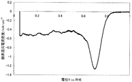
- FIG. 3 shows a current-potential curve obtained by evaluating the oxygen reducing ability of the fuel cell electrode (1-3) of Example 1-3.
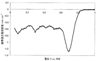
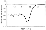
- FIG. 4 shows a current-potential curve in which the oxygen reducing ability of the fuel cell electrode (2) of Example 2 was evaluated.
- FIG. 5 is a powder X-ray diffraction spectrum of the catalyst (3) of Example 3.
- FIG. 6 shows a current-potential curve obtained by evaluating the oxygen reducing ability of the fuel cell electrode (3) of Example 3.
- FIG. 1 shows a current-potential curve obtained by evaluating the oxygen reducing ability of the fuel cell electrode (1-1) of Example 1-1.
- FIG. 2 shows a current-potential curve obtained by evaluating the oxygen reducing ability of the fuel cell electrode (
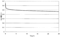
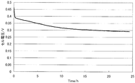
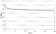
- FIG. 7 is a diagram illustrating measurement results of the constant current load measurement test of the single cell (1) of Example 3.
- FIG. 8 shows a current-potential curve in which the oxygen reducing ability of the fuel cell electrode (4) of Example 4 was evaluated.
- FIG. 9 shows a current-potential curve in which the oxygen reducing ability of the fuel cell electrode (5) of Example 5 was evaluated.
- FIG. 10 shows a current-potential curve in which the oxygen reducing ability of the fuel cell electrode (6) of Reference Example 1 was evaluated.
- FIG. 11 is a diagram illustrating a measurement result of the constant current load measurement test of the single cell (2) of Reference Example 1.
- FIG. 12 shows a current-potential curve in which the oxygen reducing ability of the fuel cell electrode (7) of Example 6 was evaluated.
- FIG. 13 shows a current-potential curve in which the oxygen reducing ability of the fuel cell electrode (8) of Example 7 was evaluated.
- FIG. 14 shows a current-potential curve in which the oxygen reducing ability of the fuel cell electrode (9) of Comparative Example 1 was evaluated.
- FIG. 15 is a powder X-ray diffraction spectrum of the catalyst (10) of Comparative Example 2.
- FIG. 16 shows a current-potential curve in which the oxygen reducing ability of the fuel cell electrode (10) of Comparative Example 2 was evaluated.
- FIG. 17 is a diagram illustrating measurement results of a constant current load measurement test of the single cell (3) of Comparative Example 2.
- FIG. 18 shows a current-potential curve in which the oxygen reducing ability of the fuel cell electrode (11) of Comparative Example 3 was evaluated.
- FIG. 19 shows a current-potential curve in which the oxygen reducing ability of the fuel cell electrode (12) of Comparative Example 4 was evaluated.
- FIG. 20 shows a current-potential curve in which the oxygen reducing ability of the fuel cell electrode (13) of Comparative Example 5 was evaluated.
- FIG. 21 shows a current-potential curve in which the oxygen reducing ability of the fuel cell electrode (14) of Comparative Example 6 was evaluated.
- FIG. 22 is an example of an exploded cross-sectional view of a single cell of a polymer electrolyte fuel cell.
- the number of atoms of M1 is the total number of atoms of those elements when M1 is composed of a plurality of elements. The same applies to M3 and M2 described later.
- the fuel cell electrode catalyst (hereinafter also referred to as “catalyst (A)”) is at least one element selected from Group 3 to 7 elements as metal elements (hereinafter also referred to as “transition metal element M1”). ) And at least one element selected from group 13 elements (hereinafter also referred to as “group 13 element M3”).
- the effects expected from the presence of the group 13 element M3 are as follows. (1) For example, by adding a group 13 element having a valence lower than that of titanium which is a transition metal element M1, the valence of titanium is stabilized to 4 or less and the active site is maintained. (2) Since the active site is stably maintained, an effect as a highly durable catalyst is also expected. (3) Even when the electrode catalyst is used in a high potential, high oxidizing atmosphere where the transition metal element M1 is eluted, the group 13 element M3 is passivated, thereby further increasing the transition metal element M1. Prevent elution.
- the transition metal element M1 is preferably at least one element selected from the group consisting of titanium, zirconium, hafnium, niobium and tantalum, particularly preferably titanium and niobium. When the transition metal element M1 is any of these elements, it is easy to obtain a highly active electrode catalyst.
- the group 13 element M3 is preferably at least one element selected from the group consisting of boron, aluminum, gallium and indium, particularly preferably aluminum and boron. When the group 13 element M3 is any of these elements, it is easy to obtain a highly active electrode catalyst.
- the ratio of the number of atoms of transition metal element M1, group 13 element M3, carbon, nitrogen and oxygen (M1: M3: carbon: nitrogen: oxygen) which is a constituent element of the fuel cell electrode catalyst of the present invention is a: c: x : Y: z, 0 ⁇ a ⁇ 1, 0 ⁇ c ⁇ 1, 0 ⁇ x ⁇ 6, 0 ⁇ y ⁇ 2, 0 ⁇ z ⁇ 3.
- a + c 1.
- the range of x is more preferably 0.15 ⁇ x ⁇ 5, further preferably 0.2 ⁇ x ⁇ 4, particularly preferably 1 ⁇ x ⁇ 3, and y Is more preferably 0.01 ⁇ y ⁇ 1.5, further preferably 0.03 ⁇ y ⁇ 1.5, particularly preferably 0.05 ⁇ y ⁇ 1, and the range of z is More preferably, 0.1 ⁇ z ⁇ 2.6, still more preferably 0.3 ⁇ z ⁇ 2, and particularly preferably 0.5 ⁇ z ⁇ 1.9.
- the range of a is more preferably 0.3 ⁇ a ⁇ 1, more preferably 0.3 ⁇ a ⁇ 0.95, and particularly preferably 0.5 ⁇ a. ⁇ 0.95.
- the values of a, c, x, y and z are values measured by the method employed in the examples described later.
- the oxygen reduction initiation potential of the catalyst (A) measured according to the following measurement method (A) is preferably 0.6 V (vs. RHE) or more, more preferably 0.7 V (vs. RHE) or more, more preferably 0.8 V (vs. RHE) or more.
- the oxygen reduction current density of the catalyst (A) measured according to the following measurement method (A) is preferably 0.5 mA / cm 2 or more at 0.6 V, more preferably 0.5 mA / cm 2 at 0.7 V. More preferably, it is 0.5 mA / cm 2 or more at 0.75 V.
- carbon carbon black (specific surface area: 100 to 300 m 2 / g) (for example, XC-72 manufactured by Cabot Corporation) is used, and the catalyst and carbon are dispersed so that the mass ratio is 95: 5.
- isopropyl alcohol: water (mass ratio) 2: 1 is used.
- NAFION registered trademark
- DE521 DuPont 5% NAFION (registered trademark) solution (DE521)
- a reversible hydrogen electrode in a sulfuric acid aqueous solution of the same concentration at a temperature of 30 ° C. in a 0.5 mol / L sulfuric acid aqueous solution in an oxygen atmosphere and a nitrogen atmosphere was used as a reference electrode.
- a current-potential curve is measured by polarization at a potential scanning speed of 5 mV / sec, a difference of 0.2 ⁇ A / cm 2 or more begins to appear in the reduction current in the oxygen atmosphere and the reduction current in the nitrogen atmosphere.
- the potential is the oxygen reduction start potential.
- the oxygen reduction current density can be determined as follows.
- a difference between a reduction current in an oxygen atmosphere and a reduction current in a nitrogen atmosphere at 0.75 V is calculated from the result of the measurement method (A).
- a value obtained by dividing the calculated value by the electrode area is defined as an oxygen reduction current density (mA / cm 2 ).
- the performance is evaluated with the oxygen reduction current density obtained at 0.7 V (vs RHE), and the current density at 0.7 V is 0.
- the performance is evaluated by the current density obtained at 0.6 V (vs RHE).
- the (110) plane interval calculated by XRD measurement is calculated by XRD measurement of a catalyst produced in the same manner as the catalyst without adding M3 (hereinafter also referred to as “catalyst (B)”). It is preferable that it is smaller than the (110) plane interval.
- the difference between the plane spacings is preferably greater than 0 and 0.006 mm or less, more preferably 0.0003 mm or more and 0.002 mm or less, and further preferably 0.0005 mm or more and 0.001 mm or less.
- the difference in the interplanar spacing is preferable in that the group 13 element is incorporated into the transition metal skeleton and the performance is improved.
- the fuel cell electrode catalyst of the present invention more preferably comprises at least M1, which is at least one element selected from Group 3-7 elements, and M2, Group 13, which is at least one element selected from iron group elements.
- M3, carbon, nitrogen and oxygen, which are at least one element selected, are used as constituent elements, and the ratio of the number of atoms of each element (M1: M2: M3: carbon: nitrogen: oxygen) is expressed as a: b: c:
- the fuel cell electrode catalyst (hereinafter also referred to as “catalyst (C)”) is M2 (which is at least one element selected from iron group elements in addition to transition metal element M1 and group 13 element M3 as a metal element). (Hereinafter also referred to as “iron group element M2”).
- the iron group element M2 is passivated to further increase the transition metal element M1. Prevent elution.
- the iron group element M2 is at least one element selected from the group consisting of iron, nickel, and cobalt, and preferably iron. When the iron group element M2 is any of these elements, it is easy to obtain a highly active electrode catalyst.
- the ratio of the number of atoms of transition metal element M1, iron group element M2, group 13 element M3, carbon, nitrogen and oxygen, which are constituent elements of the fuel cell electrode catalyst of the present invention (M1: M2: M3).
- a + b + c 1. Since the catalyst (C) contains M2 in this way, the performance becomes higher.
- the preferred ranges of x, y and z are the same as in the case of the above-mentioned catalyst (A), and the range of a is more preferably 0.3 ⁇ a ⁇ 1, more preferably 0.3 ⁇ a ⁇ 0.95, particularly preferably 0.5 ⁇ a ⁇ 0.95, and the range of b is more preferably 0.01 ⁇ b ⁇ 0.5, still more preferably 0.02 ⁇ . b ⁇ 0.4, particularly preferably 0.05 ⁇ b ⁇ 0.3.
- the values of a, b, c, x, y and z are values measured by the method employed in the examples described later.
- the oxygen reduction initiation potential of the catalyst (C) measured according to the measurement method (A) is preferably 0.6 V (vs. RHE) or more, more preferably 0.7 V (vs. RHE) or more, more preferably 0.8 V (vs. RHE) or more.
- the oxygen reduction current density of the catalyst (C) measured according to the measurement method (A) is preferably 0.6 V and 0.5 mA / cm 2 or more, more preferably 0.7 V and 0.5 mA / cm 2. More preferably, it is 0.5 mA / cm 2 or more at 0.75 V.
- the catalyst (C) has (110) plane spacing calculated by XRD measurement as an element other than M3 among the elements contained in the catalyst, and the ratio of the number of atoms of each element (M1: M2) : Carbon: nitrogen: oxygen) is a: b: x: y: z, 0 ⁇ a ⁇ 1, 0 ⁇ b ⁇ 0.5, 0 ⁇ x ⁇ 6, 0 ⁇ y ⁇ 2, 0 ⁇
- 0.0005 mm or less is preferable, and 0.0003 mm or more is more preferable.
- the (110) face spacing of the catalyst (C) is smaller than the (110) face spacing of the catalyst (D) by 0.0005 mm or more, the group 13 element is incorporated into the transition metal skeleton and the performance is improved. This is preferable.
- the specific surface area calculated by the BET method of the catalyst (A) and the catalyst (C) of the present invention is 100 m 2 / g or more, preferably 150 m 2 / g or more, more preferably 200 m 2 / g or more.
- the specific surface area is 100 m 2 / g or more, the ink dispersibility is high and high catalytic ability is obtained.
- the specific surface area is less than 100 m 2 / g, the catalyst surface area is small, so that the ink dispersibility is low, and formation of a three-phase interface becomes difficult at the time of forming the catalyst layer.
- the upper limit of the specific surface area is not particularly limited, but according to the following production method, the upper limit of the specific surface area of the obtained catalyst (A) and catalyst (C) is about 600 m 2 / g. It is about 450 m 2 / g.
- the catalyst (A) and the catalyst (C) of the present invention preferably have atoms of 3 to 7 elements, 13 elements, carbon, nitrogen and oxygen, and the 3 to 7 elements and 13 elements It has an oxide, carbide or nitride alone or a plurality of crystal structures thereof.
- the catalyst (A) and the catalyst (C) are the transition metal element and 13 A structure in which an oxygen atom site of an oxide structure is substituted with a carbon atom or a nitrogen atom while having an oxide structure of a group element, or a structure of a carbide, nitride, or carbonitride of the transition metal element and group 13 element It is presumed that it has a structure in which a site of a carbon atom or a nitrogen atom is substituted with an oxygen atom, or a mixture containing these structures.
- the production method of the catalyst (A) and the catalyst (C) of the present invention is not limited, and can be produced, for example, by the following production method.
- the method for producing the fuel cell electrode catalyst of the present invention comprises: A catalyst precursor solution is prepared by mixing a compound containing at least one element M1 selected from at least group 3-7 elements, a compound containing at least one element M3 selected from group 13 elements, a nitrogen-containing organic compound, and a solvent. Obtaining step 1, Step 2 for removing the solvent from the catalyst precursor solution to obtain a solid residue, and Step 3 for obtaining an electrode catalyst by heat-treating the solid residue obtained in Step 2 at a temperature of 500 to 1200 ° C. It is characterized by including.
- step 1 a compound containing at least one element M1 selected from at least group 3 to 7 elements (hereinafter also referred to as “transition metal M1 containing compound”), a compound containing at least one element M3 selected from group 13 (Hereinafter also referred to as “Group 13 element-containing compound”), a nitrogen-containing organic compound and a solvent are mixed to prepare a catalyst precursor solution.
- transition metal M1 containing compound a compound containing at least one element M1 selected from at least group 3 to 7 elements
- Group 13 element-containing compound a compound containing at least one element M3 selected from group 13
- nitrogen-containing organic compound and a solvent are mixed to prepare a catalyst precursor solution.
- the mixing operation may be performed by preparing a solvent in one container, adding a transition metal M1-containing compound, a group 13 element-containing compound, and a nitrogen-containing organic compound, dissolving them, and mixing them.
- a transition metal M1-containing compound solution, a group 13 element-containing compound solution, and a nitrogen-containing organic compound solution may be prepared and mixed.
- the solvent having high solubility is different for each of the transition metal M1-containing compound and the nitrogen-containing organic compound, the latter mixing operation is preferable.
- the mixing operation is preferably performed with stirring in order to increase the dissolution rate of each component in the solvent.
- the other two solutions are fixed to one solution using a pump or the like. It is preferable to supply at a speed.
- transition metal M1-containing compound solution and the group 13 element-containing compound solution little by little to the nitrogen-containing organic compound solution (that is, do not add the whole amount at once).
- the catalyst precursor solution preferably does not contain precipitates or dispersoids, but contains a small amount thereof (for example, 5% by mass or less, preferably 2% by mass or less, more preferably 1% by mass or less) based on the total amount of the solution. May be.
- the catalyst precursor solution is preferably clear, and the value measured by the liquid transparency measurement method described in JIS K0102 is preferably 1 cm or more, more preferably 2 cm or more, and even more preferably 5 cm or more. is there.
- a transition metal M1-containing compound, a group 13 element-containing compound, a nitrogen-containing organic compound, and a solvent may be placed in a pressurizable container such as an autoclave, and mixing may be performed while applying a pressure higher than normal pressure.
- the temperature at the time of mixing the transition metal M1-containing compound, the group 13 element-containing compound, the nitrogen-containing organic compound, and the solvent is, for example, 0 to 60 ° C. Assuming that a complex is formed from the transition metal M1-containing compound and the nitrogen-containing organic compound, when this temperature is excessively high, the complex is hydrolyzed and a hydroxide precipitates when the solvent contains water. It is considered that an excellent catalyst cannot be obtained. If this temperature is excessively low, the transition metal M1-containing compound is precipitated before the complex is formed, and it is considered that an excellent catalyst cannot be obtained.
- Transition metal M1-containing compound Specific examples of M1 contained in the transition metal M1-containing compound include titanium, zirconium, hafnium, niobium, and tantalum. These may be contained individually by 1 type and may be contained 2 or more types.
- titanium, zirconium, niobium and tantalum are preferable, and titanium and zirconium are more preferable from the viewpoint of cost and performance of the obtained catalyst.
- the transition metal M1-containing compound preferably has at least one selected from an oxygen atom and a halogen atom.
- Specific examples thereof include metal phosphates, metal sulfates, metal nitrates, and metal organic acid salts.
- Metal acid halides intermediate hydrolysates of metal halides
- metal alkoxides metal halides
- metal halides and metal hypohalites metal complexes. These may be used alone or in combination of two or more.
- the metal alkoxide is preferably the transition metal methoxide, propoxide, isopropoxide, ethoxide, butoxide, or isobutoxide, and more preferably the transition metal isopropoxide, ethoxide, or butoxide.
- the metal alkoxide may have one type of alkoxy group or may have two or more types of alkoxy groups.
- transition metal M1-containing compound having an oxygen atom an oxide, an alkoxide, an acetylacetone complex, an acid chloride, and a sulfate are preferable, and from the viewpoint of cost, an oxide, an alkoxide, and an acetylacetone complex are more preferable. From the viewpoint of solubility in a solvent, alkoxides and acetylacetone complexes are more preferable.
- metal halide chloride, bromide and iodide of the transition metal are preferable, and as the metal acid halide, acid chloride, acid bromide and acid iodide of the transition metal are preferable.
- transition metal M1-containing compound examples include Titanium dioxide, titanium oxide having 1 to 2 oxygen atoms per titanium atom, titanium tetramethoxide, titanium tetraethoxide, titanium tetrapropoxide, titanium tetraisopropoxide, titanium tetrabutoxide, titanium tetraisobutoxide, Titanium tetrapentoxide, titanium tetraacetylacetonate, titanium oxydiacetylacetonate, tris (acetylacetonato) dititanium chloride, titanium tetrachloride, titanium trichloride, titanium oxychloride, titanium tetrabromide, titanium tribromide Titanium compounds such as titanium oxybromide, titanium tetraiodide, titanium triiodide, titanium oxyiodide; Niobium pentoxide, niobium oxide having 2.5 or less oxygen atoms per niobium atom, niod
- the resulting catalyst becomes fine particles with a uniform particle size, and its activity is high, Titanium tetraethoxide, titanium tetrachloride, titanium oxychloride, titanium tetraisopropoxide, titanium tetraacetylacetonate, Niobium pentaethoxide, niobium pentachloride, niobium oxychloride, niobium pentaisopropoxide, Zirconium tetraethoxide, zirconium tetrachloride, zirconium oxychloride, zirconium tetraisopropoxide, zirconium tetraacetylacetonate, Tantalum pentamethoxide, tantalum pentaethoxide, tantalum pentachloride, tantalum oxychloride, tantalum pentaisopropoxide, and tantalum tetraethoxyacetylacetonate,
- the catalyst (C) In the case of producing the catalyst (C), a compound containing at least one element M2 selected from a transition metal M1 containing compound and an iron group element (hereinafter also referred to as “iron group element M2 containing compound”), 13 Group element-containing compounds are used.
- iron group element M2 containing compound an iron group element
- iron group element M2 in the iron group element M2 containing compound examples include iron, nickel, and cobalt, and iron is preferable from the viewpoint of the balance between the cost and the performance of the obtained catalyst.
- iron group element M2-containing compound Iron (II) chloride, iron (III) chloride, iron (III) sulfate, iron (II) sulfide, iron (III) sulfide, potassium ferrocyanide, potassium ferricyanide, ammonium ferrocyanide, ammonium ferricyanide, iron ferrocyanide , Iron (II) nitrate, iron (III) nitrate, iron (II) oxalate, iron (III) oxalate, iron (II) phosphate, iron (III) phosphate ferrocene, iron (II) hydroxide, water Iron compounds such as iron (III) oxide, iron (II) oxide, iron (III) oxide, triiron tetroxide, iron (II) acetate, iron (II) lactate, iron (III) citrate; cobalt chloride (II) ), Cobalt (III) chloride, cobalt (II) sulfate
- Iron (II) chloride, iron (III) chloride, potassium ferrocyanide, potassium ferricyanide, ammonium ferrocyanide, ammonium ferricyanide, iron (II) acetate, iron (II) lactate, cobalt (II) chloride, cobalt chloride (III) ), Cobalt (II) acetate, and cobalt (II) lactate More preferred are iron (II) chloride, iron (III) chloride, potassium ferrocyanide, potassium ferricyanide, ammonium ferrocyanide, ammonium ferricyanide, iron (II) acetate, and iron (II) lactate.
- Group 13 element-containing compound examples include boron, aluminum, gallium, and indium. These may be contained individually by 1 type and may be contained 2 or more types.
- aluminum and boron are preferable from the viewpoint of the performance of the obtained catalyst.
- the group 13 element-containing compound preferably has at least one selected from an oxygen atom and a halogen atom.
- a phosphoric acid compound a sulfuric acid compound, a nitric acid compound, an organic acid compound, an acid halide (metal halide) Intermediate hydrolysates), alkoxides, halides, halogen acid compounds and hypohalous acid compounds, complexes. These may be used alone or in combination of two or more.
- alkoxide methoxide, propoxide, isopropoxide, ethoxide, butoxide, and isobutoxide of the group 13 element are preferable, and isopropoxide, ethoxide, and butoxide of the group 13 element are more preferable.
- the alkoxide may have one type of alkoxy group or may have two or more types of alkoxy groups.
- an oxide, an alkoxide, an acetylacetone complex, an acid chloride, and a sulfuric acid compound are preferable, and from the viewpoint of cost, an oxide, an alkoxide, and an acetylacetone complex are more preferable. From the viewpoint of solubility in a solvent, alkoxides and acetylacetone complexes are more preferable.
- chlorides, bromides and iodides of the group 13 element are preferable, and as the halogen oxides, acid chlorides, acid bromides and acid iodides are preferable.
- group 13 element-containing compound examples include aluminum sulfide, aluminum sulfate, aluminum fluoride, aluminum chloride, aluminum bromide, aluminum iodide, aluminum hydroxide, aluminum phosphate, aluminum triisopropoxide, aluminum trimethoxy.
- the resulting catalyst is a fine particle having a uniform particle size, and since its activity is high, aluminum triisopropoxide, aluminum trimethoxide, aluminum triethoxide, aluminum acetylacetonate, aluminum chloride, Triisopropyl borate, trimethoxyborane, triethoxyborane, boron chloride, Gallium hydroxide, gallium acetylacetonate, indium hydroxide, indium chloride, indium acetylacetonate, triisopropylindium, trimethoxyindium, triethoxyindium are preferred, aluminum triisopropoxide, aluminum acetylacetonate, triborate More preferred are isopropyl, triisopropyl gallium, gallium acetylacetonate, triisopropylindium, and indium acetylacetonate.
- the nitrogen-containing organic compound is a compound that can be a ligand capable of coordinating to a metal atom in the transition metal M1-containing compound and the iron group element M2-containing compound (preferably a compound that can form a mononuclear complex).
- a compound that can be a multidentate ligand preferably a bidentate ligand or a tridentate ligand (can form a chelate) is more preferable.
- the nitrogen-containing organic compounds may be used alone or in combination of two or more.
- the nitrogen-containing organic compound is preferably an amino group, a nitrile group, an imide group, an imine group, a nitro group, an amide group, an azido group, an aziridine group, an azo group, an isocyanate group, an isothiocyanate group, an oxime group, a diazo group, It has a functional group such as a nitroso group, or a ring such as a pyrrole ring, a porphyrin ring, an imidazole ring, a pyridine ring, a pyrimidine ring, or a pyrazine ring (these functional groups and rings are also collectively referred to as “nitrogen-containing molecular groups”). .
- the nitrogen-containing organic compound has a nitrogen-containing molecular group in the molecule, the nitrogen-containing organic compound is more strongly coordinated with the transition metal atom derived from the transition metal M1-containing compound and the iron group element M2-containing compound after mixing in Step 1. It is considered possible.
- an amino group, an imine group, an amide group, a pyrrole ring, a pyridine ring and a pyrazine ring are more preferable, an amino group, an imine group, a pyrrole ring and a pyrazine ring are more preferable, and an amino group and a pyrazine ring are preferable.
- an amino group, an imine group, a pyrrole ring and a pyrazine ring are more preferable, and an amino group and a pyrazine ring are preferable.
- nitrogen-containing organic compound but not containing an oxygen atom
- nitrogen-containing organic compound include melamine, ethylenediamine, ethylenediamine dihydrochloride, triazole, acetonitrile, acrylonitrile, ethyleneimine, aniline, pyrrole, and polyethyleneimine.
- ethylenediamine and ethylenediamine dihydrochloride are preferred because of the high activity of the resulting catalyst.
- the nitrogen-containing organic compound is preferably a hydroxyl group, a carboxyl group, a formyl group, a halocarbonyl group, a sulfonic acid group, a phosphoric acid group, a ketone group, an ether group or an ester group (these are collectively referred to as an “oxygen-containing molecular group”).
- an oxygen-containing molecular group a group that has an oxygen-containing molecular group in the molecule
- the nitrogen-containing organic compound can be strongly coordinated with the transition metal atom derived from the transition metal M1-containing compound and the iron group element M2-containing compound through the mixing in Step 1. it is conceivable that.
- a carboxyl group and a formyl group are particularly preferable because the activity of the resulting catalyst is particularly high.
- the nitrogen-containing organic compound containing an oxygen atom in the molecule is preferably a compound having the nitrogen-containing molecular group and the oxygen-containing molecular group. It is considered that such a compound can be particularly strongly coordinated with the transition metal atom derived from the transition metal M1-containing compound and the iron group element M2-containing compound through the step 1.
- amino acids having an amino group and a carboxyl group, and derivatives thereof are preferable.
- amino acids examples include alanine, arginine, asparagine, aspartic acid, cysteine, glutamine, glutamic acid, glycine, histidine, isoleucine, leucine, lysine, methionine, phenylalanine, serine, threonine, tryptophan, tyrosine, valine, norvaline, glycylglycine, Triglycine and tetraglycine are preferred, and the resulting catalyst has a high activity.
- Alanine, glycine, lysine, methionine, and tyrosine are more preferred, and the resulting catalyst exhibits a very high activity, so that alanine, glycine, and lysine are particularly preferred. preferable.
- nitrogen-containing organic compound containing an oxygen atom in the molecule include acylpyrroles such as acetylpyrrole, acylimidazoles such as pyrrolecarboxylic acid and acetylimidazole, carbonyldiimidazole and imidazole Carboxylic acid, pyrazole, acetanilide, pyrazinecarboxylic acid, piperidinecarboxylic acid, piperazinecarboxylic acid, morpholine, pyrimidinecarboxylic acid, nicotinic acid, 2-pyridinecarboxylic acid, 2,4-pyridinedicarboxylic acid, 8-quinolinol, and polyvinylpyrrolidone
- compounds that can be bidentate ligands such as pyrrole-2-carboxylic acid, imidazole-4-carboxylic acid, 2-pyrazinecarboxylic acid, 2-piperidinecarbox Acid, 2-piperazine carboxylic
- Ratio of total number of carbon atoms B of the nitrogen-containing organic compound used in step 1 to total number A of transition metal elements of the transition metal M1-containing compound and iron group element M2-containing compound used in step 1 can reduce the amount of components desorbed as carbon compounds such as carbon dioxide and carbon monoxide during the heat treatment in step 3, that is, the amount of exhaust gas can be reduced during catalyst production.
- it is 200 or less, more preferably 150 or less, more preferably 80 or less, particularly preferably 30 or less, and preferably 1 or more, more preferably 2 or more, and still more preferably from the viewpoint of obtaining a catalyst with good activity. 3 or more, particularly preferably 5 or more.
- Ratio of the total number of nitrogen atoms C of the nitrogen-containing organic compound used in step 1 to the total number A of transition metal elements of the transition metal M1-containing compound and iron group element M2-containing compound used in step 1 is preferably 28 or less, more preferably 17 or less, still more preferably 12 or less, particularly preferably 8.5 or less, from the viewpoint of obtaining a catalyst having a good activity, and a catalyst having a good activity is obtained. In view of the above, it is preferably 1 or more, more preferably 2.5 or more, further preferably 3 or more, and particularly preferably 3.5 or more.
- Ratio of the total number of atoms D of the group 13 element-containing compound used in step 1 to the total number of atoms A of the transition metal element of the transition metal M1-containing compound and the iron group element M2-containing compound used in step 1 is preferably 30 or less, more preferably 25 or less, particularly preferably 15 or less from the viewpoint of obtaining a catalyst having a good activity, and preferably 0.001 from the viewpoint of obtaining a catalyst having a good activity. Above, more preferably 0.005 or more, particularly preferably 0.01 or more.
- solvent examples include water, acetic acid, and alcohols.
- alcohols ethanol, methanol, butanol, propanol and ethoxyethanol are preferable, and ethanol and methanol are more preferable.
- an acid in the solvent As the acid, acetic acid, nitric acid, hydrochloric acid, phosphoric acid and citric acid are preferable, and acetic acid and nitric acid are more preferable. These may be used alone or in combination of two or more.
- a precipitation inhibitor By using a precipitation inhibitor, a clear catalyst precursor solution can be obtained while suppressing the occurrence of precipitation derived from the transition metal M1-containing compound.
- a strong acid such as hydrochloric acid may be added as a precipitation inhibitor. preferable.
- the transition metal M1-containing compound is a metal complex and water is used alone or water and another compound as the solvent, a compound having a diketone structure is preferred as a precipitation inhibitor, and diacetyl, acetylacetone, 2,5-hexanedione and dimedone are more preferred.
- the precipitation inhibitor may be added at any stage in step 1.
- a catalyst precursor solution is preferably prepared by preparing a solution containing the transition metal M1-containing compound, a group 13 element-containing compound and the precipitation inhibitor, and then mixing this solution with the nitrogen-containing organic compound. To prepare.
- step 1 is performed in this manner, the occurrence of precipitation can be more reliably suppressed.
- step 1 a solution containing the transition metal M1-containing compound, a group 13 element-containing compound and the precipitation inhibitor is preferably prepared, and then this solution And the nitrogen-containing organic compound and the iron group element M2-containing compound are mixed to obtain a catalyst precursor solution.
- step 2 the solvent is removed from the catalyst precursor solution obtained in step 1 to obtain a solid residue.
- the removal of the solvent may be performed in the air, or may be performed in an atmosphere of nitrogen gas or inert gas (for example, argon or helium).
- nitrogen gas or inert gas for example, argon or helium.
- nitrogen and argon are preferable from the viewpoint of cost, and nitrogen is more preferable.
- the temperature at the time of solvent removal may be room temperature when the vapor pressure of the solvent is high, but from the viewpoint of mass production of the catalyst, it is preferably 30 ° C or higher, more preferably 40 ° C or higher, and still more preferably. From the viewpoint of not decomposing the catalyst precursor that is estimated to be a metal complex such as a chelate, which is contained in the solution obtained in Step 1 at 50 ° C or higher, preferably 250 ° C or lower, more preferably 150 ° C. Below, it is 110 degrees C or less more preferably.
- the removal of the solvent may be performed under atmospheric pressure when the vapor pressure of the solvent is high, but in order to remove the solvent in a shorter time, it is performed under reduced pressure (for example, 0.1 Pa to 0.1 MPa). Also good.
- the solvent may be removed while the mixture obtained in Step 1 is allowed to stand, but in order to obtain a more uniform solid residue, it is preferable to remove the solvent while stirring the mixture.
- the composition or aggregation of the solid residue obtained in step 2 may be uneven. Even in such a case, if a solid residue is mixed and pulverized to obtain a more uniform and fine powder in Step 3, a catalyst having a more uniform particle size can be obtained. .
- Step 3 the solid residue obtained in Step 2 is heat-treated to obtain an electrode catalyst.
- the temperature during this heat treatment is 500 to 1200 ° C., preferably 600 to 1150 ° C., more preferably 700 to 1050 ° C. in order to obtain high durability and a high specific surface area.
- the temperature of the heat treatment is too higher than the above range, sintering and grain growth occur between the particles of the obtained electrode catalyst, resulting in a decrease in the specific surface area of the electrode catalyst. As a result, the processability during processing into a catalyst layer is poor.
- the temperature of the heat treatment is too lower than the above range, an electrode catalyst having high activity cannot be obtained. Within the above range, a higher heat treatment temperature is desirable from the viewpoint of improving the durability of the catalyst.
- Examples of the heat treatment method include a stationary method (for example, a method using an electric furnace), a stirring method (for example, a method using a rotary kiln), a dropping method, and a powder trapping method.
- a stationary method for example, a method using an electric furnace
- a stirring method for example, a method using a rotary kiln
- a dropping method for example, a powder trapping method.
- the rate of temperature rise is not particularly limited, but is preferably about 1 ° C./min to 100 ° C./min, more preferably 5 ° C./min to 50 ° C./min. is there.
- the heating time is preferably 0.1 to 10 hours, more preferably 0.2 to 5 hours, and further preferably 0.2 to 3 hours.
- the heating time of the electrode catalyst particles is 0.1 to 10 hours, preferably 0.2 to 5 hours. When the heating time is within the above range, uniform electrode catalyst particles tend to be formed.
- the heating time of the solid residue is usually 10 minutes to 5 hours, preferably 10 minutes to 2 hours.
- the average residence time calculated from the steady sample flow rate in the furnace is set as the heating time.
- the heating time of the solid residue is usually 0.5 to 10 minutes, preferably 0.5 to 3 minutes.
- the heating time is within the above range, uniform electrode catalyst particles tend to be formed.
- the heating time of the solid residue is 0.2 seconds to 1 minute, preferably 0.2 to 10 seconds.
- the atmosphere for the heat treatment is preferably a nitrogen or inert gas atmosphere from the viewpoint of increasing the activity of the obtained electrode catalyst.
- nitrogen, argon, and helium are preferable and nitrogen and argon are more preferable because they are relatively inexpensive and easily available.
- These gases may be used individually by 1 type, and 2 or more types may be mixed and used for them.
- the obtained electrode catalyst may exhibit higher catalytic performance.
- the reactive gas include nitrogen gas, oxygen gas, hydrogen gas, carbon-containing gas such as methane, and nitrogen-containing gas such as ammonia.
- the hydrogen gas concentration is, for example, 100% by volume or less, preferably 0.01 to 10% by volume, more preferably 1 to 5% by volume.
- the concentration of oxygen gas is, for example, 10% by volume or less, preferably 0.01 to 10% by volume, more preferably 0.01 to 5% by volume.
- the heat treatment is preferably performed. Is performed in an atmosphere containing oxygen gas.
- the heat treatment product may be crushed.
- pulverization it may be possible to improve the workability in producing an electrode using the obtained electrode catalyst and the characteristics of the obtained electrode.
- a roll rolling mill for example, a ball rolling mill, a ball mill, a small-diameter ball mill (bead mill), a medium stirring mill, an airflow grinder, a mortar, an automatic kneading mortar, a tank disintegrator, or a jet mill can be used.
- the catalyst (A) of the present invention can be used as an alternative catalyst for a noble metal catalyst such as platinum.
- the catalyst (A) includes the catalyst (C).
- the catalyst (A) of the present invention may contain a noble metal such as platinum as long as the above conditions are satisfied.
- the catalyst (A) of the present invention preferably contains no precious metal such as platinum.
- the catalyst (A) of the present invention can also be used as a catalyst that replaces a part of a noble metal catalyst such as platinum. That is, the catalyst (A) of the present invention and a noble metal catalyst such as platinum can be used in combination.
- the fuel cell catalyst layer of the present invention is characterized by including the catalyst (A).
- the fuel cell catalyst layer includes an anode catalyst layer and a cathode catalyst layer, and the catalyst (A) can be used for both. Since the catalyst (A) is excellent in durability and has a large oxygen reducing ability, it is preferably used for the cathode catalyst layer.
- the fuel cell catalyst layer of the present invention preferably further contains an electron conductive powder.
- the reduction current can be further increased.
- the electron conductive powder is considered to increase the reduction current because it generates an electrical contact for inducing an electrochemical reaction in the catalyst (A).
- the electron conductive particles are usually used as a catalyst carrier.
- the catalyst (A) has a certain degree of conductivity. However, since the catalyst (A) gives more electrons or the anti-substrate receives more electrons from the catalyst (A), the catalyst (A) Carrier particles for imparting properties may be mixed. These carrier particles may be mixed with the catalyst (A) produced through the steps 1 to 3, or may be mixed at any stage of the steps 1 to 3.
- the material of the electron conductive particles examples include carbon, a conductive polymer, a conductive ceramic, a metal, or a conductive inorganic oxide such as tungsten oxide or iridium oxide, which can be used alone or in combination. .
- the electron conductive particles made of carbon have a large specific surface area, and are easily available with a small particle size at low cost, and are excellent in chemical resistance and high potential resistance, carbon alone or carbon and other electrons.
- a mixture with conductive particles is preferred. That is, the fuel cell catalyst layer preferably contains the catalyst (A) and carbon.
- Examples of carbon include carbon black, graphite, activated carbon, carbon nanotube, carbon nanofiber, carbon nanohorn, fullerene, porous carbon, and graphene. If the particle size of the electron conductive particles made of carbon is too small, it becomes difficult to form an electron conduction path. If the particle size is too large, the gas diffusibility of the fuel cell catalyst layer and the catalyst utilization rate tend to decrease. Therefore, the thickness is preferably 10 to 1000 nm, more preferably 10 to 100 nm.
- the weight ratio of the catalyst (A) to the electron conductive particles is preferably 4: 1 to 1000: 1.
- the conductive polymer is not particularly limited.
- polypyrrole, polyaniline, and polythiophene are preferable, and polypyrrole is more preferable.
- These conductive polymers may contain a dopant for obtaining high conductivity.
- the polymer electrolyte is not particularly limited as long as it is generally used in a fuel cell catalyst layer.
- a perfluorocarbon polymer having a sulfonic acid group for example, Nafion (registered trademark) (DuPont 5% NAFION (registered trademark) solution (DE521))
- a hydrocarbon having a sulfonic acid group Polymer compounds, polymer compounds doped with inorganic acids such as phosphoric acid, organic / inorganic hybrid polymers partially substituted with proton-conducting functional groups, polymer matrix impregnated with phosphoric acid solution or sulfuric acid solution For example, proton conductors.
- Nafion (NAFION (registered trademark)) DuPont 5% NAFION (registered trademark) solution (DE521)
- Nafion (NAFION (registered trademark)) DuPont 5% NAFION (registered trademark) solution (DE521)
- the fuel cell catalyst layer of the present invention can be used for either an anode catalyst layer or a cathode catalyst layer.
- the catalyst layer for a fuel cell of the present invention includes a catalyst layer (catalyst catalyst for cathode) provided on the cathode of a fuel cell because it contains a catalyst having high oxygen reducing ability and hardly corroded even in a high potential in an acidic electrolyte. Layer).
- a catalyst layer provided on the cathode of a membrane electrode assembly provided in a polymer electrolyte fuel cell.
- Examples of a method for dispersing the catalyst (A) on the electron conductive particles as a carrier include air flow dispersion and liquid dispersion. Dispersion in liquid is preferred because a catalyst (A) and electron conductive particles dispersed in a solvent can be used in the fuel cell catalyst layer forming step. Examples of the dispersion in the liquid include a method using an orifice contraction flow, a method using a rotating shear flow, and a method using an ultrasonic wave.
- the solvent used for dispersion in the liquid is not particularly limited as long as it does not erode the catalyst or electron conductive particles and can be dispersed, but a volatile liquid organic solvent or water is generally used.
- the electrolyte and the dispersant may be further dispersed at the same time.
- the method for forming the catalyst layer for the fuel cell is not particularly limited.
- a suspension containing the catalyst (A) electron conductive particles and an electrolyte that is, an ink is applied to an electrolyte membrane or a gas diffusion layer described later.
- coating is mentioned.
- the application method include a dipping method, a screen printing method, a roll coating method, and a spray method.
- a suspension containing the catalyst (A), electron conductive particles, and an electrolyte is formed on the electrolyte membrane by a transfer method.
- the method of forming a catalyst layer is mentioned.
- the electrode of the present invention is characterized by having the fuel cell catalyst layer and a porous support layer.
- the electrode of the present invention can be used as either a cathode or an anode. Since the electrode of the present invention is excellent in durability and has a large catalytic ability, it is more industrially superior when used as a cathode.
- the porous support layer is a layer that diffuses gas (hereinafter also referred to as “gas diffusion layer”).
- gas diffusion layer may be anything as long as it has electron conductivity, high gas diffusibility, and high corrosion resistance.
- carbon-based porous materials such as carbon paper and carbon cloth are used. Materials and aluminum foil coated with stainless steel and corrosion-resistant materials for weight reduction are used.
- the membrane electrode assembly of the present invention is a membrane electrode assembly having a cathode, an anode, and an electrolyte membrane disposed between the cathode and the anode, wherein the cathode and / or the anode is the electrode. It is characterized by that.
- the catalytic ability and durability of the membrane electrode assembly can be evaluated by, for example, the cell voltage calculated as follows and the slope ⁇ of the voltage drop over time.
- the membrane electrode assembly 11 is sandwiched between a sealing material (gasket 12), a separator 13 with a gas flow path, a current collector 14 and a rubber heater 15, and fixed with bolts.
- a single cell of a polymer electrolyte fuel cell is manufactured by tightening to a pressure (4N).
- the cell voltage is preferably 0.1 V or higher, more preferably 0.2 V or higher, and even more preferably 0.3 V or higher.
- the slope ⁇ (mV / h) of the voltage drop is desirably 3 mV / h or less, more desirably 2 mV / h or less, and further desirably 1.5 mV / h or less.
- an electrolyte membrane using a perfluorosulfonic acid system or a hydrocarbon electrolyte membrane is generally used.
- a membrane or porous body in which a polymer microporous membrane is impregnated with a liquid electrolyte is used.
- a membrane filled with a polymer electrolyte may be used.
- the fuel cell of the present invention is characterized by comprising the membrane electrode assembly.
- Fuel cell electrode reactions occur at the so-called three-phase interface (electrolyte-electrode catalyst-reaction gas). Fuel cells are classified into several types depending on the electrolyte used, etc., and include molten carbonate type (MCFC), phosphoric acid type (PAFC), solid oxide type (SOFC), and solid polymer type (PEFC). . Especially, it is preferable to use the membrane electrode assembly of this invention for a polymer electrolyte fuel cell.
- MCFC molten carbonate type
- PAFC phosphoric acid type
- SOFC solid oxide type
- PEFC solid polymer type
- the fuel cell using the catalyst (A) of the present invention is characterized by high performance even when noble metal is used, and extremely inexpensive compared with the case where platinum is used as a catalyst.
- the fuel cell of the present invention has at least one function selected from the group consisting of a power generation function, a light emission function, a heat generation function, a sound generation function, an exercise function, a display function, and a charge function, The performance of the portable article can be improved.
- the fuel cell is preferably provided on the surface or inside of an article.
- Specific example of article provided with fuel cell of the present invention include buildings, houses, buildings such as tents, fluorescent lamps, LEDs, etc., organic EL, street lamps, indoor lighting, lighting fixtures such as traffic lights, machines, Automotive equipment including the vehicle itself, home appliances, agricultural equipment, electronic equipment, portable information terminals including mobile phones, beauty equipment, portable tools, sanitary equipment such as bathroom accessories, furniture, toys, decorations, bulletin boards , Outdoor supplies such as cooler boxes, outdoor generators, teaching materials, artificial flowers, objects, power supplies for cardiac pacemakers, power supplies for heating and cooling devices with Peltier elements.
- Nitrogen / oxygen About 0.1 g of a sample was weighed and sealed in Ni-Cup, and then measured with an ON analyzer.
- Metal element About 0.1 g of a sample was weighed into a platinum dish, and an acid was added for thermal decomposition. This thermally decomposed product was fixed, diluted, and quantified by ICP-MS.
- BET specific surface area 0.15 g of a sample was sampled, and the specific surface area was measured with a fully automatic BET specific surface area measuring device Macsorb (manufactured by Mountec Co., Ltd.).
- the pretreatment time and pretreatment temperature were set at 30 ° C. and 200 ° C., respectively.
- Ink dispersibility was evaluated according to the following criteria. Good: No catalyst precipitate is observed on the bottom surface. Poor: Catalyst precipitate is confirmed on the bottom surface.
- X-ray powder diffraction (XRD) The sample was subjected to powder X-ray diffraction using a rotor flex made by Rigaku Corporation.
- the number of diffraction line peaks in powder X-ray diffraction of each sample was counted by regarding a signal that can be detected with a ratio (S / N) of signal (S) to noise (N) of 2 or more as one peak.
- the noise (N) is the width of the baseline.
- Anode production example 1 Preparation of anode ink An aqueous solution containing 5 g of Nafion (NAFION (registered trademark) 0.25 g) and 0.6 g of platinum-supported carbon (TEC10E60E, manufactured by Tanaka Kikinzoku Kogyo) in 50 ml of pure water. (Registered trademark)) aqueous solution, manufactured by Wako Pure Chemical Industries, Ltd.)), and mixed with an ultrasonic disperser (UT-106H type Sharp Manufacturing System) for 1 hour to prepare an anode ink (1). Was prepared.
- NAFION registered trademark
- TEC10E60E platinum-supported carbon
- electrode having anode catalyst layer A gas diffusion layer (carbon paper (TGP-H-060, manufactured by Toray Industries, Inc.)) was degreased by dipping in acetone for 30 seconds, dried, and then 10% polytetrafluoroethylene (Hereinafter also referred to as “PTFE”.) It was immersed in an aqueous solution for 30 seconds.
- carbon paper TGP-H-060, manufactured by Toray Industries, Inc.
- PTFE polytetrafluoroethylene
- the soaked product was dried at room temperature and heated at 350 ° C. for 1 hour to obtain a gas diffusion layer (hereinafter also referred to as “GDL”) having PTFE dispersed in the carbon paper and having water repellency.
- GDL gas diffusion layer
- the anode ink (1) was applied to the surface of the GDL having a size of 5 cm ⁇ 5 cm at 80 ° C. by an automatic spray coating apparatus (manufactured by Sanei Tech Co., Ltd.). By repeating spray coating, an electrode having an anode catalyst layer (1) having a platinum (Pt) amount per unit area of 1 mg / cm 2 was produced.
- Example 1-1 Preparation of catalyst 9.37 g of titanium tetraisopropoxide (manufactured by Junsei Chemical Co., Ltd.), 0.702 g of aluminum triisopropoxide (manufactured by Wako Pure Chemical Industries, Ltd.) and acetylacetone (Junsei) 5 as transition metal M1-containing compounds .12 g was added to a solution with 32 mL of acetic acid (manufactured by Wako Pure Chemical Industries, Ltd.), and a transition metal M1-containing mixture solution was prepared while stirring at room temperature.
- This powder is put in a quartz furnace, heated to 890 ° C. at a heating rate of 20 ° C./min in an atmosphere containing 4% by volume of hydrogen gas and 96% by volume of nitrogen gas, held at 890 ° C. for 15 minutes, and naturally cooled.
- a powdery catalyst hereinafter also referred to as “catalyst (1-1)” was obtained.
- Table 1 shows the BET specific surface area, elemental analysis results, and ink dispersibility evaluation of this catalyst. With the catalyst (1-1), no precipitate was observed on the bottom surface of the ink, and high ink dispersibility was observed.
- the produced fuel cell electrode (1-1) was started from 30 V, 1.1 V in a 0.5 mol / L sulfuric acid aqueous solution in an oxygen atmosphere and a nitrogen atmosphere, and 5 mV on the base potential side. Polarization was performed at a potential scanning speed of / sec, and current-potential curves were measured respectively. The value obtained by dividing the current value by the electrode area and subtracting the current density observed in the nitrogen atmosphere from the current density observed in the oxygen atmosphere was defined as the oxygen reduction current density. At that time, a reversible hydrogen electrode in an aqueous sulfuric acid solution having the same concentration was used as a reference electrode.
- the catalytic ability of the produced fuel cell electrode (1-1) was evaluated based on the oxygen reduction starting potential and the oxygen reduction current density.
- a potential indicating an oxygen reduction current density of 0.2 ⁇ A / cm 2 is defined as an oxygen reduction start potential.
- FIG. 1 shows a current-potential curve obtained by the above measurement.
- Example 1-2 Catalyst preparation Catalyst (1-2) was synthesized in the same manner as in Example 1-1, except that the calcination temperature was 1000 ° C. Table 1 shows the BET specific surface area, elemental analysis results, and ink dispersibility evaluation of this catalyst. With the catalyst (1-2), no precipitate was observed on the bottom surface of the ink, and high ink dispersibility was observed.
- a fuel cell electrode (1-2) was obtained in the same manner as in Example 1-1 except that the catalyst (1-2) was used instead of the catalyst (1-1).
- FIG. 2 shows a current-potential curve obtained by the above measurement.
- the catalyst (1-2) produced in Example 1-2 has an oxygen reduction current density of 1.00 mA / cm at an oxygen reduction starting potential of 0.92 V (vs. RHE) and 0.75 V (vs. RHE). 2 and was found to have high catalytic ability.
- Example 1-3 A catalyst (1-3) was synthesized by the same method as in Example 1-1 except that the calcination temperature was 1050 ° C. Table 1 shows the BET specific surface area, elemental analysis results, and ink dispersibility evaluation of this catalyst. With the catalyst (1-3), no precipitate was observed on the bottom surface of the ink, and high ink dispersibility was observed.
- a fuel cell electrode (1-3) was obtained in the same manner as in Example 1-1 except that the catalyst (1-3) was used instead of the catalyst (1-1).
- Catalytic activity was evaluated in the same manner as in Example 1-1 except that the fuel cell electrode (1-3) was used instead of the fuel cell electrode (1-1).
- FIG. 3 shows a current-potential curve obtained by the above measurement.
- the catalyst (1-3) produced in Example 1-3 has an oxygen reduction current density of 0.72 mA / cm at an oxygen reduction starting potential of 0.91 V (vs. RHE) and 0.75 V (vs. RHE). 2 and was found to have high catalytic ability.
- Example 2 Preparation of catalyst 9.37 g of titanium tetraisopropoxide (manufactured by Junsei Chemical Co., Ltd.), 0.070 g of aluminum triisopropoxide (manufactured by Wako Pure Chemical Industries, Ltd.) and acetylacetone (Junsei) 5 as transition metal M1-containing compounds .12 g was added to a solution with 32 mL of acetic acid (manufactured by Wako Pure Chemical Industries, Ltd.), and a transition metal M1-containing mixture solution was prepared while stirring at room temperature.
- a fuel cell electrode (2) was obtained in the same manner as in Example 1-1 except that the catalyst (2) was used instead of the catalyst (1-1).
- Catalytic activity was evaluated in the same manner as in Example 1-1 except that the fuel cell electrode (2) was used instead of the fuel cell electrode (1-1).
- Example 3 Preparation of catalyst 9.37 g of titanium tetraisopropoxide (manufactured by Pure Chemical Co., Ltd.), 0.176 g of aluminum triisopropoxide (manufactured by Wako Pure Chemical Industries, Ltd.) and acetylacetone (Pure Chemical) 5 as transition metal M1-containing compounds .12 g was added to a solution with 32 mL of acetic acid (manufactured by Wako Pure Chemical Industries, Ltd.), and a transition metal M1-containing mixture solution was prepared while stirring at room temperature.
- a fuel cell electrode (3) was obtained in the same manner as in Example 1-1 except that the catalyst (3) was used instead of the catalyst (1-1).
- Catalytic activity was evaluated in the same manner as in Example 1-1 except that the fuel cell electrode (3) was used instead of the fuel cell electrode (1-1).
- the cathode ink (1) was applied to the surface of the GDL having a size of 5 cm ⁇ 5 cm by a bar coater at 80 ° C., and the total amount of the catalyst (3) and carbon black was 2 per unit area.
- An electrode (hereinafter also referred to as “cathode (1)”) having a cathode catalyst layer (1) of 5 mg / cm 2 on the GDL surface was produced.
- the cathode (1) was used as the cathode.
- an electrode (hereinafter also referred to as “anode (1)”) having an anode catalyst layer (1) on the surface of the GDL produced in the anode production example 1 was prepared.
- a fuel cell membrane electrode assembly (hereinafter also referred to as “MEA”) in which the electrolyte membrane is disposed between the cathode and the anode was produced as follows.
- single cell (1) a single cell of the polymer electrolyte fuel cell (hereinafter also referred to as “single cell (1)”) (cell area: 5 cm 2 ).
- 4N a predetermined surface pressure
- single cell (1) a single cell of the polymer electrolyte fuel cell (hereinafter also referred to as “single cell (1)”) (cell area: 5 cm 2 ).
- Hydrogen was supplied as fuel to the anode side at a flow rate of 0.1 liter / minute, oxygen was supplied as an oxidant at a flow rate of 0.1 liter / minute to the cathode side, and a single cell ( In 1), a constant current load measurement test of 0.1 A / cm 2 was performed.
- the measurement results are shown in FIG. It shows that the higher the cell voltage, the higher the catalytic performance in MEA, and the lower the value of the slope ⁇ (mV / h) of the voltage drop over time, the higher the durability of the catalyst.
- the slope ⁇ of the voltage drop was obtained by linearly approximating the curve portion after 5 hours from the start of measurement by the least square method.
- the slope ⁇ of the voltage drop in the single cell (1) was 1.2 mV / h, and it was confirmed that the catalyst durability was high.
- FIG. 8 shows a current-potential curve obtained by the above measurement.
- the catalyst (4) produced in Example 4 has an oxygen reduction starting potential of 0.95 V (vs. RHE), an oxygen reduction current density of 0.90 mA / cm 2 at 0.75 V (vs. RHE), It was found to have high catalytic ability.
- Example 5 As a transition metal M1-containing compound, 4.685 g of titanium tetraisopropoxide (manufactured by Junsei Chemical Co., Ltd.), 4.212 g of aluminum triisopropoxide, and 5.12 g of acetylacetone (Junsei Kagaku) were mixed with acetic acid (Wako Pure Chemical Industries, Ltd.). In addition to the solution with 32 mL, a transition metal M1-containing mixture solution was prepared while stirring at room temperature.
- a catalyst (5) was synthesized in the same manner as in Example 1-1, except that the calcination temperature was 1000 ° C. Table 1 shows the BET specific surface area, elemental analysis results and dispersibility evaluation of this catalyst. With the catalyst (5), no precipitate was observed on the bottom surface of the ink, and high ink dispersibility was observed.
- a fuel cell electrode (5) was obtained in the same manner as in Example 1-1 except that the catalyst (5) was used instead of the catalyst (1-1).
- the catalytic ability was evaluated in the same manner as in Example 1-1 except that the fuel cell electrode (5) was used instead of the fuel cell electrode (1-1).
- FIG. 9 shows a current-potential curve obtained by the above measurement.
- glycine manufactured by Wako Pure Chemical Industries, Ltd.
- 120 mL of pure water were added as nitrogen-containing organic compounds, and the mixture was stirred and completely dissolved at room temperature to prepare a nitrogen-containing organic compound-containing mixture solution.
- the transition metal M1-containing mixture solution was slowly added to the nitrogen-containing organic compound-containing mixture solution to obtain a transparent catalyst precursor solution.
- the water bath temperature was set to about 60 ° C. under reduced pressure in a nitrogen atmosphere, and the solvent was slowly evaporated while heating and stirring the catalyst precursor solution.
- the solid residue obtained by completely evaporating the solvent was finely and uniformly crushed in a mortar to obtain a powder.
- a catalyst (6) was synthesized by the same method as in Example 1-1, except that the firing temperature was 1000 ° C. Table 1 shows the BET specific surface area, elemental analysis results, and ink dispersibility evaluation of this catalyst. In the catalyst (6), high ink dispersibility was observed.
- FIG. 10 shows a current-potential curve obtained by the above measurement.
- the catalyst (6) produced in Reference Example 1 had an oxygen reduction starting potential of 0.76 V (vs. RHE) and an oxygen reduction current density of 0.21 mA / cm 2 at 0.6 V (vs. RHE). .
- the membrane electrode assembly for fuel cell (hereinafter referred to as “MEA”) was prepared in the same manner as in Example 3 except that catalyst (6) was used instead of catalyst (3). (Also referred to as “(2)”), and a single cell of a polymer electrolyte fuel cell (hereinafter “single cell”) was prepared in the same manner as in Example 3 except that MEA (2) was used instead of MEA (1). (Also referred to as “(2)”).
- the measurement results are shown in FIG. It shows that the higher the cell voltage, the higher the catalytic ability in MEA, and the lower the value of the slope ⁇ (mV / h) of the voltage drop with time, the higher the durability of the catalyst.
- the slope ⁇ of the voltage drop in the single cell (2) was 1.6 mV / h, and it was confirmed that the catalyst durability was high.
- a catalyst (7) was synthesized by the same method as in Example 1-1, except that the firing temperature was 1000 ° C. Table 1 shows the BET specific surface area, elemental analysis results and dispersibility evaluation of this catalyst. In the catalyst (7), no precipitate was observed on the bottom surface of the ink, and high ink dispersibility was observed.
- Catalytic activity was evaluated in the same manner as in Example 1-1 except that the fuel cell electrode (7) was used instead of the fuel cell electrode (1-1).
- FIG. 12 shows a current-potential curve obtained by the above measurement.
- a catalyst (8) was synthesized by the same method as in Example 1-1, except that the firing temperature was 1000 ° C. Table 1 shows the BET specific surface area, elemental analysis results, and ink dispersibility evaluation of this catalyst. In the catalyst (8), no precipitate was observed on the bottom surface of the ink, and high ink dispersibility was observed.
- FIG. 13 shows a current-potential curve obtained by the above measurement.
- the catalyst (8) produced in Example 7 has an oxygen reduction starting potential of 0.98 V (vs. RHE), an oxygen reduction current density at 0.75 V (vs. RHE) of 0.57 mA / cm 2 , It was found to have high catalytic ability.
- Catalytic activity was evaluated in the same manner as in Example 1-1 except that the fuel cell electrode (9) was used instead of the fuel cell electrode (1-1).
- FIG. 14 shows a current-potential curve obtained by the above measurement.
- Catalyst preparation A catalyst (10) was synthesized in the same manner as in Example 3 except that aluminum triisopropoxide was not added.
- Table 1 shows the BET specific surface area, elemental analysis results and dispersibility evaluation of this catalyst. In the catalyst (10), no precipitate was observed on the bottom surface of the ink, and high ink dispersibility was observed.
- FIG. 15 shows the XRD measurement results. The distance between the (110) planes of the catalyst (10) obtained by XRD measurement was 3.2484 mm.
- Catalytic activity was evaluated in the same manner as in Example 1-1 except that the fuel cell electrode (10) was used instead of the fuel cell electrode (1-1).
- the catalyst (10) produced in Comparative Example 2 has an oxygen reduction starting potential of 0.88 V (vs. RHE), an oxygen reduction current density at 0.75 V (vs. RHE) of 0.30 mA / cm 2 , It was found that the catalytic ability was low.
- a constant current load measurement test was performed in the same manner as in Example 3 except that the single cell (3) was used instead of the single cell (1).
- a fuel cell electrode (11) was obtained in the same manner as in Example 1-1 except that the catalyst (11) was used instead of the catalyst (1-1).
- Catalytic activity was evaluated in the same manner as in Example 1-1 except that the fuel cell electrode (11) was used instead of the fuel cell electrode (1-1).
- a fuel cell electrode (12) was obtained in the same manner as in Example 1-1 except that the catalyst (12) was used instead of the catalyst (1-1).
- the catalyst (12) produced in Comparative Example 4 has an oxygen reduction starting potential of 0.76 V (vs. RHE) and an oxygen reduction current density of 0.01 mA / cm 2 at 0.75 V (vs. RHE), It was found that the catalytic ability was low.
- catalyst 2 g of titanium oxide (anatase type, 100 m 2 / g), which is a transition metal M1-containing compound, and 0.75 g of carbon black (Vulcan XC72 Cabot) are mixed well in a mortar, placed in a tube furnace, and hydrogen gas is added.
- the catalyst is heated to 1700 ° C. at a rate of temperature increase of 10 ° C./min, held at 1700 ° C. for 3 hours, and naturally cooled to be a powdered catalyst (hereinafter also referred to as “catalyst 13”). ) was manufactured.
- Catalytic activity was evaluated in the same manner as in Example 1-1 except that the fuel cell electrode (13) was used instead of the fuel cell electrode (1-1).
- a fuel cell electrode (14) was obtained in the same manner as in Example 1-1 except that the catalyst (14) was used instead of the catalyst (1-1).
- MEA Membrane electrode assembly
- Gasket 12 Gasket 13 Separator 14 Current collector 15 Rubber heater
Landscapes
- Chemical & Material Sciences (AREA)
- Engineering & Computer Science (AREA)
- Chemical Kinetics & Catalysis (AREA)
- Electrochemistry (AREA)
- General Chemical & Material Sciences (AREA)
- Materials Engineering (AREA)
- Manufacturing & Machinery (AREA)
- Catalysts (AREA)
- Inert Electrodes (AREA)
Abstract
Priority Applications (5)
| Application Number | Priority Date | Filing Date | Title |
|---|---|---|---|
| KR1020147000881A KR101544330B1 (ko) | 2011-06-14 | 2012-01-12 | 연료 전지용 전극 촉매 및 그 제조 방법 |
| JP2012548667A JP5255160B1 (ja) | 2011-06-14 | 2012-01-12 | 燃料電池用電極触媒およびその製造方法 |
| CN201280029121.8A CN103619477B (zh) | 2011-06-14 | 2012-01-12 | 燃料电池用电极催化剂和其制造方法 |
| US14/125,399 US20140120454A1 (en) | 2011-06-14 | 2012-01-12 | Fuel cell electrode catalyst and production process thereof |
| EP12800085.8A EP2722106B1 (fr) | 2011-06-14 | 2012-01-12 | Catalyseur d'électrode de pile à combustible et son procédé de production |
Applications Claiming Priority (2)
| Application Number | Priority Date | Filing Date | Title |
|---|---|---|---|
| JP2011132102 | 2011-06-14 | ||
| JP2011-132102 | 2011-06-14 |
Publications (1)
| Publication Number | Publication Date |
|---|---|
| WO2012172823A1 true WO2012172823A1 (fr) | 2012-12-20 |
Family
ID=47356825
Family Applications (1)
| Application Number | Title | Priority Date | Filing Date |
|---|---|---|---|
| PCT/JP2012/050529 Ceased WO2012172823A1 (fr) | 2011-06-14 | 2012-01-12 | Catalyseur d'électrode de pile à combustible et son procédé de production |
Country Status (6)
| Country | Link |
|---|---|
| US (1) | US20140120454A1 (fr) |
| EP (1) | EP2722106B1 (fr) |
| JP (1) | JP5255160B1 (fr) |
| KR (1) | KR101544330B1 (fr) |
| CN (1) | CN103619477B (fr) |
| WO (1) | WO2012172823A1 (fr) |
Cited By (3)
| Publication number | Priority date | Publication date | Assignee | Title |
|---|---|---|---|---|
| CN105377423A (zh) * | 2013-07-12 | 2016-03-02 | 昭和电工株式会社 | 氧还原催化剂及其用途 |
| US10229301B2 (en) | 2013-11-28 | 2019-03-12 | Datalogic Ip Tech S.R.L. | Optical code reading system with dynamic image regionalization |
| WO2026023533A1 (fr) * | 2024-07-24 | 2026-01-29 | 富士フイルム株式会社 | Catalyseur pour électrolyse de l'eau, assemblage membrane-électrodes, module d'électrolyse de l'eau et électrolyseur d'eau |
Families Citing this family (5)
| Publication number | Priority date | Publication date | Assignee | Title |
|---|---|---|---|---|
| WO2011099493A1 (fr) * | 2010-02-10 | 2011-08-18 | 昭和電工株式会社 | Procédé de production de catalyseur d'électrode de pile à combustible, procédé de production d'oxycarbonitrure de métal de transition, catalyseur d'électrode de pile à combustible et leurs utilisations |
| TWI592213B (zh) * | 2016-03-16 | 2017-07-21 | 國立清華大學 | 觸媒層及其製造方法、膜電極組及其製造方法與燃料電池 |
| US10978718B2 (en) | 2017-08-29 | 2021-04-13 | Uchicago Argonne, Llc | Carbon dioxide reduction electro catalysts prepared for metal organic frameworks |
| US11033888B2 (en) * | 2017-08-30 | 2021-06-15 | Uchicago Argonne, Llc | Nanofiber electrocatalyst |
| CN115602858A (zh) * | 2022-10-12 | 2023-01-13 | 北京科技大学(Cn) | 一种碳包覆过渡金属氮化物纳米颗粒制备方法及其作为orr催化剂的应用 |
Citations (4)
| Publication number | Priority date | Publication date | Assignee | Title |
|---|---|---|---|---|
| WO2008111570A1 (fr) * | 2007-03-09 | 2008-09-18 | Sumitomo Chemical Company, Limited | Ensemble membrane-électrode et pile à combustible utilisant l'ensemble membrane-électrode |
| WO2009091043A1 (fr) * | 2008-01-18 | 2009-07-23 | Showa Denko K.K. | Catalyseur, son procédé de production et son utilisation |
| WO2009119523A1 (fr) * | 2008-03-24 | 2009-10-01 | 昭和電工株式会社 | Catalyseur et procédé de fabrication et son utilisation |
| JP2011115760A (ja) * | 2009-12-07 | 2011-06-16 | Nisshinbo Holdings Inc | 触媒担持用担体、触媒担持体、電極及び電池 |
Family Cites Families (4)
| Publication number | Priority date | Publication date | Assignee | Title |
|---|---|---|---|---|
| JP2008258152A (ja) * | 2007-03-09 | 2008-10-23 | Sumitomo Chemical Co Ltd | 膜−電極接合体およびこれを用いた燃料電池 |
| JP5537433B2 (ja) * | 2008-10-06 | 2014-07-02 | 昭和電工株式会社 | 触媒およびその製造方法ならびにその用途 |
| JP5738898B2 (ja) * | 2010-01-29 | 2015-06-24 | エバレデイ バツテリ カンパニー インコーポレーテツド | 二酸化マンガンを含む触媒電極を有する電気化学電池を製造する方法 |
| US9118083B2 (en) * | 2011-01-14 | 2015-08-25 | Showa Denko K.K | Method for producing fuel cell electrode catalyst, fuel cell electrode catalyst, and uses thereof |
-
2012
- 2012-01-12 JP JP2012548667A patent/JP5255160B1/ja not_active Expired - Fee Related
- 2012-01-12 KR KR1020147000881A patent/KR101544330B1/ko not_active Expired - Fee Related
- 2012-01-12 EP EP12800085.8A patent/EP2722106B1/fr not_active Not-in-force
- 2012-01-12 CN CN201280029121.8A patent/CN103619477B/zh not_active Expired - Fee Related
- 2012-01-12 US US14/125,399 patent/US20140120454A1/en not_active Abandoned
- 2012-01-12 WO PCT/JP2012/050529 patent/WO2012172823A1/fr not_active Ceased
Patent Citations (4)
| Publication number | Priority date | Publication date | Assignee | Title |
|---|---|---|---|---|
| WO2008111570A1 (fr) * | 2007-03-09 | 2008-09-18 | Sumitomo Chemical Company, Limited | Ensemble membrane-électrode et pile à combustible utilisant l'ensemble membrane-électrode |
| WO2009091043A1 (fr) * | 2008-01-18 | 2009-07-23 | Showa Denko K.K. | Catalyseur, son procédé de production et son utilisation |
| WO2009119523A1 (fr) * | 2008-03-24 | 2009-10-01 | 昭和電工株式会社 | Catalyseur et procédé de fabrication et son utilisation |
| JP2011115760A (ja) * | 2009-12-07 | 2011-06-16 | Nisshinbo Holdings Inc | 触媒担持用担体、触媒担持体、電極及び電池 |
Cited By (4)
| Publication number | Priority date | Publication date | Assignee | Title |
|---|---|---|---|---|
| CN105377423A (zh) * | 2013-07-12 | 2016-03-02 | 昭和电工株式会社 | 氧还原催化剂及其用途 |
| US9660272B2 (en) | 2013-07-12 | 2017-05-23 | Showa Denko K.K. | Oxygen reduction catalyst and use thereof |
| US10229301B2 (en) | 2013-11-28 | 2019-03-12 | Datalogic Ip Tech S.R.L. | Optical code reading system with dynamic image regionalization |
| WO2026023533A1 (fr) * | 2024-07-24 | 2026-01-29 | 富士フイルム株式会社 | Catalyseur pour électrolyse de l'eau, assemblage membrane-électrodes, module d'électrolyse de l'eau et électrolyseur d'eau |
Also Published As
| Publication number | Publication date |
|---|---|
| EP2722106A1 (fr) | 2014-04-23 |
| JPWO2012172823A1 (ja) | 2015-02-23 |
| KR101544330B1 (ko) | 2015-08-12 |
| EP2722106A4 (fr) | 2014-12-03 |
| US20140120454A1 (en) | 2014-05-01 |
| KR20140022105A (ko) | 2014-02-21 |
| JP5255160B1 (ja) | 2013-08-07 |
| CN103619477A (zh) | 2014-03-05 |
| EP2722106B1 (fr) | 2017-12-13 |
| CN103619477B (zh) | 2016-06-01 |
Similar Documents
| Publication | Publication Date | Title |
|---|---|---|
| JP6061998B2 (ja) | 燃料電池用電極触媒、遷移金属炭窒酸化物およびその用途 | |
| JP5855023B2 (ja) | 触媒担体の製造方法、複合触媒の製造方法、複合触媒、およびこれを用いた燃料電池 | |
| JP5302468B2 (ja) | 酸素還元触媒およびその製造方法、並びに固体高分子形燃料電池 | |
| JP5766138B2 (ja) | 燃料電池用電極触媒の製造方法、燃料電池用電極触媒およびその用途 | |
| EP2744024B1 (fr) | Procédé de production de catalyseur d'électrode pour piles à combustible | |
| JP5819280B2 (ja) | 燃料電池用電極触媒およびその用途 | |
| JP5255160B1 (ja) | 燃料電池用電極触媒およびその製造方法 |
Legal Events
| Date | Code | Title | Description |
|---|---|---|---|
| ENP | Entry into the national phase |
Ref document number: 2012548667 Country of ref document: JP Kind code of ref document: A |
|
| 121 | Ep: the epo has been informed by wipo that ep was designated in this application |
Ref document number: 12800085 Country of ref document: EP Kind code of ref document: A1 |
|
| WWE | Wipo information: entry into national phase |
Ref document number: 14125399 Country of ref document: US |
|
| NENP | Non-entry into the national phase |
Ref country code: DE |
|
| ENP | Entry into the national phase |
Ref document number: 20147000881 Country of ref document: KR Kind code of ref document: A |