WO2012172900A1 - Système d'alimentation électrique sans contact de type résonance - Google Patents
Système d'alimentation électrique sans contact de type résonance Download PDFInfo
- Publication number
- WO2012172900A1 WO2012172900A1 PCT/JP2012/062180 JP2012062180W WO2012172900A1 WO 2012172900 A1 WO2012172900 A1 WO 2012172900A1 JP 2012062180 W JP2012062180 W JP 2012062180W WO 2012172900 A1 WO2012172900 A1 WO 2012172900A1
- Authority
- WO
- WIPO (PCT)
- Prior art keywords
- resonance
- frequency
- coil
- power
- power supply
- Prior art date
- Legal status (The legal status is an assumption and is not a legal conclusion. Google has not performed a legal analysis and makes no representation as to the accuracy of the status listed.)
- Ceased
Links
Images



Classifications
-
- H—ELECTRICITY
- H04—ELECTRIC COMMUNICATION TECHNIQUE
- H04B—TRANSMISSION
- H04B5/00—Near-field transmission systems, e.g. inductive or capacitive transmission systems
- H04B5/70—Near-field transmission systems, e.g. inductive or capacitive transmission systems specially adapted for specific purposes
- H04B5/79—Near-field transmission systems, e.g. inductive or capacitive transmission systems specially adapted for specific purposes for data transfer in combination with power transfer
-
- B—PERFORMING OPERATIONS; TRANSPORTING
- B60—VEHICLES IN GENERAL
- B60L—PROPULSION OF ELECTRICALLY-PROPELLED VEHICLES; SUPPLYING ELECTRIC POWER FOR AUXILIARY EQUIPMENT OF ELECTRICALLY-PROPELLED VEHICLES; ELECTRODYNAMIC BRAKE SYSTEMS FOR VEHICLES IN GENERAL; MAGNETIC SUSPENSION OR LEVITATION FOR VEHICLES; MONITORING OPERATING VARIABLES OF ELECTRICALLY-PROPELLED VEHICLES; ELECTRIC SAFETY DEVICES FOR ELECTRICALLY-PROPELLED VEHICLES
- B60L53/00—Methods of charging batteries, specially adapted for electric vehicles; Charging stations or on-board charging equipment therefor; Exchange of energy storage elements in electric vehicles
- B60L53/10—Methods of charging batteries, specially adapted for electric vehicles; Charging stations or on-board charging equipment therefor; Exchange of energy storage elements in electric vehicles characterised by the energy transfer between the charging station and the vehicle
- B60L53/12—Inductive energy transfer
- B60L53/122—Circuits or methods for driving the primary coil, e.g. supplying electric power to the coil
-
- B—PERFORMING OPERATIONS; TRANSPORTING
- B60—VEHICLES IN GENERAL
- B60L—PROPULSION OF ELECTRICALLY-PROPELLED VEHICLES; SUPPLYING ELECTRIC POWER FOR AUXILIARY EQUIPMENT OF ELECTRICALLY-PROPELLED VEHICLES; ELECTRODYNAMIC BRAKE SYSTEMS FOR VEHICLES IN GENERAL; MAGNETIC SUSPENSION OR LEVITATION FOR VEHICLES; MONITORING OPERATING VARIABLES OF ELECTRICALLY-PROPELLED VEHICLES; ELECTRIC SAFETY DEVICES FOR ELECTRICALLY-PROPELLED VEHICLES
- B60L53/00—Methods of charging batteries, specially adapted for electric vehicles; Charging stations or on-board charging equipment therefor; Exchange of energy storage elements in electric vehicles
- B60L53/10—Methods of charging batteries, specially adapted for electric vehicles; Charging stations or on-board charging equipment therefor; Exchange of energy storage elements in electric vehicles characterised by the energy transfer between the charging station and the vehicle
- B60L53/12—Inductive energy transfer
- B60L53/126—Methods for pairing a vehicle and a charging station, e.g. establishing a one-to-one relation between a wireless power transmitter and a wireless power receiver
-
- H—ELECTRICITY
- H01—ELECTRIC ELEMENTS
- H01F—MAGNETS; INDUCTANCES; TRANSFORMERS; SELECTION OF MATERIALS FOR THEIR MAGNETIC PROPERTIES
- H01F38/00—Adaptations of transformers or inductances for specific applications or functions
- H01F38/14—Inductive couplings
-
- H—ELECTRICITY
- H01—ELECTRIC ELEMENTS
- H01M—PROCESSES OR MEANS, e.g. BATTERIES, FOR THE DIRECT CONVERSION OF CHEMICAL ENERGY INTO ELECTRICAL ENERGY
- H01M10/00—Secondary cells; Manufacture thereof
- H01M10/42—Methods or arrangements for servicing or maintenance of secondary cells or secondary half-cells
- H01M10/46—Accumulators structurally combined with charging apparatus
-
- H—ELECTRICITY
- H02—GENERATION; CONVERSION OR DISTRIBUTION OF ELECTRIC POWER
- H02J—ELECTRIC POWER NETWORKS; CIRCUIT ARRANGEMENTS OR SYSTEMS FOR SUPPLYING OR DISTRIBUTING ELECTRIC POWER; SYSTEMS FOR STORING ELECTRIC ENERGY
- H02J50/00—Circuit arrangements or systems for wireless supply or distribution of electric power
- H02J50/10—Circuit arrangements or systems for wireless supply or distribution of electric power using inductive coupling
- H02J50/12—Circuit arrangements or systems for wireless supply or distribution of electric power using inductive coupling of the resonant type
-
- H—ELECTRICITY
- H02—GENERATION; CONVERSION OR DISTRIBUTION OF ELECTRIC POWER
- H02J—ELECTRIC POWER NETWORKS; CIRCUIT ARRANGEMENTS OR SYSTEMS FOR SUPPLYING OR DISTRIBUTING ELECTRIC POWER; SYSTEMS FOR STORING ELECTRIC ENERGY
- H02J7/00—Circuit arrangements for charging or discharging batteries or for supplying loads from batteries
- H02J7/90—Regulation of charging or discharging current or voltage
- H02J7/933—Regulation of charging or discharging current or voltage the cycle being controlled or terminated in response to electric parameters
-
- H—ELECTRICITY
- H04—ELECTRIC COMMUNICATION TECHNIQUE
- H04B—TRANSMISSION
- H04B5/00—Near-field transmission systems, e.g. inductive or capacitive transmission systems
- H04B5/20—Near-field transmission systems, e.g. inductive or capacitive transmission systems characterised by the transmission technique; characterised by the transmission medium
- H04B5/24—Inductive coupling
- H04B5/26—Inductive coupling using coils
- H04B5/266—One coil at each side, e.g. with primary and secondary coils
-
- H—ELECTRICITY
- H02—GENERATION; CONVERSION OR DISTRIBUTION OF ELECTRIC POWER
- H02J—ELECTRIC POWER NETWORKS; CIRCUIT ARRANGEMENTS OR SYSTEMS FOR SUPPLYING OR DISTRIBUTING ELECTRIC POWER; SYSTEMS FOR STORING ELECTRIC ENERGY
- H02J7/00—Circuit arrangements for charging or discharging batteries or for supplying loads from batteries
- H02J7/40—Circuit arrangements for charging or discharging batteries or for supplying loads from batteries characterised by the exchange of charge or discharge related data
- H02J7/42—Circuit arrangements for charging or discharging batteries or for supplying loads from batteries characterised by the exchange of charge or discharge related data with electronic devices having internal batteries, e.g. mobile phones
-
- Y—GENERAL TAGGING OF NEW TECHNOLOGICAL DEVELOPMENTS; GENERAL TAGGING OF CROSS-SECTIONAL TECHNOLOGIES SPANNING OVER SEVERAL SECTIONS OF THE IPC; TECHNICAL SUBJECTS COVERED BY FORMER USPC CROSS-REFERENCE ART COLLECTIONS [XRACs] AND DIGESTS
- Y02—TECHNOLOGIES OR APPLICATIONS FOR MITIGATION OR ADAPTATION AGAINST CLIMATE CHANGE
- Y02E—REDUCTION OF GREENHOUSE GAS [GHG] EMISSIONS, RELATED TO ENERGY GENERATION, TRANSMISSION OR DISTRIBUTION
- Y02E60/00—Enabling technologies; Technologies with a potential or indirect contribution to GHG emissions mitigation
- Y02E60/10—Energy storage using batteries
-
- Y—GENERAL TAGGING OF NEW TECHNOLOGICAL DEVELOPMENTS; GENERAL TAGGING OF CROSS-SECTIONAL TECHNOLOGIES SPANNING OVER SEVERAL SECTIONS OF THE IPC; TECHNICAL SUBJECTS COVERED BY FORMER USPC CROSS-REFERENCE ART COLLECTIONS [XRACs] AND DIGESTS
- Y02—TECHNOLOGIES OR APPLICATIONS FOR MITIGATION OR ADAPTATION AGAINST CLIMATE CHANGE
- Y02T—CLIMATE CHANGE MITIGATION TECHNOLOGIES RELATED TO TRANSPORTATION
- Y02T10/00—Road transport of goods or passengers
- Y02T10/60—Other road transportation technologies with climate change mitigation effect
- Y02T10/70—Energy storage systems for electromobility, e.g. batteries
-
- Y—GENERAL TAGGING OF NEW TECHNOLOGICAL DEVELOPMENTS; GENERAL TAGGING OF CROSS-SECTIONAL TECHNOLOGIES SPANNING OVER SEVERAL SECTIONS OF THE IPC; TECHNICAL SUBJECTS COVERED BY FORMER USPC CROSS-REFERENCE ART COLLECTIONS [XRACs] AND DIGESTS
- Y02—TECHNOLOGIES OR APPLICATIONS FOR MITIGATION OR ADAPTATION AGAINST CLIMATE CHANGE
- Y02T—CLIMATE CHANGE MITIGATION TECHNOLOGIES RELATED TO TRANSPORTATION
- Y02T10/00—Road transport of goods or passengers
- Y02T10/60—Other road transportation technologies with climate change mitigation effect
- Y02T10/7072—Electromobility specific charging systems or methods for batteries, ultracapacitors, supercapacitors or double-layer capacitors
-
- Y—GENERAL TAGGING OF NEW TECHNOLOGICAL DEVELOPMENTS; GENERAL TAGGING OF CROSS-SECTIONAL TECHNOLOGIES SPANNING OVER SEVERAL SECTIONS OF THE IPC; TECHNICAL SUBJECTS COVERED BY FORMER USPC CROSS-REFERENCE ART COLLECTIONS [XRACs] AND DIGESTS
- Y02—TECHNOLOGIES OR APPLICATIONS FOR MITIGATION OR ADAPTATION AGAINST CLIMATE CHANGE
- Y02T—CLIMATE CHANGE MITIGATION TECHNOLOGIES RELATED TO TRANSPORTATION
- Y02T90/00—Enabling technologies or technologies with a potential or indirect contribution to GHG emissions mitigation
- Y02T90/10—Technologies relating to charging of electric vehicles
- Y02T90/12—Electric charging stations
-
- Y—GENERAL TAGGING OF NEW TECHNOLOGICAL DEVELOPMENTS; GENERAL TAGGING OF CROSS-SECTIONAL TECHNOLOGIES SPANNING OVER SEVERAL SECTIONS OF THE IPC; TECHNICAL SUBJECTS COVERED BY FORMER USPC CROSS-REFERENCE ART COLLECTIONS [XRACs] AND DIGESTS
- Y02—TECHNOLOGIES OR APPLICATIONS FOR MITIGATION OR ADAPTATION AGAINST CLIMATE CHANGE
- Y02T—CLIMATE CHANGE MITIGATION TECHNOLOGIES RELATED TO TRANSPORTATION
- Y02T90/00—Enabling technologies or technologies with a potential or indirect contribution to GHG emissions mitigation
- Y02T90/10—Technologies relating to charging of electric vehicles
- Y02T90/14—Plug-in electric vehicles
Definitions
- the present invention relates to a resonance type non-contact power feeding system.
- Patent Document 1 Conventionally, it has been proposed to transmit power using magnetic field resonance (see, for example, Patent Document 1).
- Patent Document 2 a design method of a non-contact power transmission device that is easy to design and manufacture has been proposed (see, for example, Patent Document 2).
- the design method of the non-contact power transmission device of Patent Document 2 when the relationship between the input impedance and the frequency of the resonance system is graphed, the frequency at which the input impedance is maximized and the frequency at which the input impedance is maximized are determined.
- the frequency of the AC power supply is set to a frequency at which the input impedance is minimized.
- Patent Document 1 does not disclose a specific method for specifying the resonance frequency of a resonance system that performs magnetic field resonance. Therefore, it has been difficult to design and manufacture a resonance type non-contact power feeding system that efficiently transmits power.
- Patent Document 2 discloses a specific method for specifying the resonance frequency of a resonance system, and a resonance-type non-contact power transmission device can be easily designed.
- An object of the present invention is to provide a resonance type non-contact power feeding system that is easy to design and manufacture and has high power transmission efficiency.
- a power supply facility including a power supply unit, a primary resonance coil that receives power supply from the power supply unit, and the power from the primary resonance coil as a magnetic field
- a power receiving facility including a secondary side resonance coil that receives power by resonance and a load to which the power received by the secondary side resonance coil is supplied, and at least the primary side resonance coil and the secondary side resonance coil And a resonance-type non-contact power feeding system in which a resonance system is constituted by the load.
- the output frequency f o of the power supply unit the frequency f 1 ⁇ f o ⁇ frequency f 2, the frequency f 3 ⁇ f o ⁇ frequency f 4, ⁇ ⁇ ⁇ , the frequency f 2n-1 ⁇ f o ⁇ frequency f 2n is set to one range of the frequency f 1, f 2, f 3 , f 4, ⁇ , f 2n-1, f 2n (f 1 ⁇ f 2 ⁇ f 3 ⁇ ⁇ f 2n ⁇ 1 ⁇ f 2n ), Z 1 , Z 2 , Z 3 ,..., Z 2n ⁇ 1 , Z 2n represent the input impedances of the resonance system when power of the frequency is supplied to the resonance system.
- Z 1 Z 2
- Z 3 Z 4
- Z 2n ⁇ 1 Z 2n .
- the output frequency f o of the power supply unit satisfies the above conditions, it is possible to increase the power transmission efficiency.
- the output frequency of the power supply must be set to a frequency that satisfies the conditions permitted by the Radio Law, and this frequency is the resonance of the resonant wireless power supply system. It is necessary to set the resonance frequency of the system or a value close to the resonance frequency.
- the resonance of the resonance system configured by using parts corresponding to the magnitude of the power to be transmitted to the load, such as the primary resonance coil and the secondary resonance coil constituting the resonance system.
- the frequency can be easily set so as to be a frequency that satisfies the conditions permitted for use in the Radio Law. Therefore, the design and manufacture of the resonance type non-contact power feeding system becomes easy.
- the induction coil which supplies the electric power supplied from the said power supply part to the said primary side resonance coil by electromagnetic induction, or the said secondary side resonance coil to at least one of the said electric power feeding installation and the said electric power reception installation
- An induction coil for taking out the electric power received by the electromagnetic induction is provided, and at least the induction coil, the primary side resonance coil, the secondary side resonance coil, and the load constitute a resonance system.
- At least two resonance coils that is, the primary side resonance coil and the secondary side resonance coil exist.
- at least one induction coil of an induction coil that supplies electric power supplied from the power supply unit to the primary resonance coil by electromagnetic induction and an induction coil that extracts electric power received by the secondary resonance coil by electromagnetic induction is provided. If it is provided, it becomes easier to adjust to the aligned state.
- the configuration including all of the primary side resonance coil, the secondary side resonance coil, and the two induction coils is easier to adjust to the matching state.
- the induction coil is provided in both the power feeding facility and the power receiving facility. Therefore, it becomes easier to adjust the induction coil to a matching state as compared with the case where the induction coil is provided only in one of the power feeding facility and the power receiving facility.
- the power supply facility includes a matching unit that matches an input impedance of the resonance system and an impedance viewed from the input end of the resonance system to the power supply unit side, and a matching unit that adjusts the matching unit And a control means (matching device controller).
- the matching unit provided in the power supply equipment is adjusted by the matching unit control means so as to match the input impedance of the resonance system and the impedance viewed from the input end of the resonance system to the power supply unit side. . Therefore, even if the input impedance of the resonance system changes, the power transmission efficiency can be maintained in a good state. Further, it is possible to cope with a change in the input impedance of the resonance system in the power feeding facility without obtaining information on the power receiving facility.
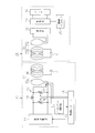
- the block diagram of the resonance type non-contact charge system of one Embodiment The circuit diagram which abbreviate
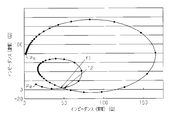
- the graph which shows the relationship between the real part and imaginary part of input impedance at the time of supplying electric power with a different frequency.
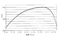
- the graph which shows the relationship between the output frequency of a high frequency power supply, and electric power transmission efficiency.
- the graph which shows the relationship between the output frequency of a high frequency power supply, and electric power transmission efficiency.
- a resonance type non-contact charging system as a resonance type non-contact power feeding system includes a power feeding facility 10 provided on the ground side and a power receiving facility 30 mounted on a vehicle as a moving body. Yes.
- the power supply facility 10 includes a high frequency power source 11 as a power source, a matching unit 12 connected to an output unit of the high frequency power source 11, a primary coil 13, an impedance measuring unit (impedance measuring unit) 14, and a power source side controller 15. It has.
- the impedance measuring means 14 a power measuring device and a phase measuring device are used.
- the power receiving facility includes a secondary coil 31, a rectifier 32, a charger 33, a battery (secondary battery) 34 connected to the charger 33, and a vehicle controller 35.
- the rectifier 32, the charger 33, and the battery 34 constitute a load.
- the primary side coil 13, the secondary side coil 31, and the load constitute a resonance system.
- the primary coil 13 is composed of a primary coil 13a as an induction coil and a primary resonance coil 13b.
- the primary coil 13a is connected to the high frequency power supply 11 via the matching unit 12.
- the primary coil 13a and the primary side resonance coil 13b are disposed so as to be coaxially connected, and a capacitor C is connected to the primary side resonance coil 13b.
- the primary coil 13a is coupled to the primary side resonance coil 13b by electromagnetic induction, and AC power supplied from the high frequency power supply 11 to the primary coil 13a is supplied to the primary side resonance coil 13b by electromagnetic induction.
- the matching unit 12 includes two variable capacitors 16 and 17 and an inductor 18.
- One variable capacitor 16 is connected to the high frequency power supply 11, and the other variable capacitor 17 is connected in parallel to the primary coil 13a.
- the inductor 18 is connected between the variable capacitors 16 and 17. The impedance of the matching unit 12 is changed by changing the capacitance of the variable capacitors 16 and 17.
- the impedance measuring means 14 is connected to the primary coil 13 a of the primary side coil 13, and the measurement result is output to the power supply side controller 15.
- the power supply controller 15 adjusts the matching unit 12 based on the measurement result of the impedance measuring means 14 so as to match the input impedance of the resonance system with the impedance viewed from the input end of the resonance system to the high frequency power supply 11 side.
- the impedance viewed from the resonance system input end toward the high frequency power supply 11 is the impedance from the power supply unit (high frequency power supply 11) to the resonance system input end.
- the power supply side controller 15 also functions as a matching unit control means (matching unit control unit).
- the secondary coil 31 includes a secondary coil 31a as an induction coil and a secondary resonance coil 31b.
- the secondary coil 31a and the secondary resonance coil 31b are disposed so as to be coaxially connected, and a capacitor C is connected to the secondary resonance coil 31b.
- the secondary coil 31a is coupled to the secondary side resonance coil 31b by electromagnetic induction, and AC power supplied from the primary side resonance coil 13b to the secondary side resonance coil 31b by resonance is supplied to the secondary coil 31a by electromagnetic induction.
- the secondary coil 31 a is connected to the rectifier 32.
- the primary resonance coil 13b and the secondary resonance coil 31b are formed in the same manner, and capacitors having the same capacitance value are used as the capacitors C.
- the output frequency f o is, satisfy the condition used in the Radio Law is allowed. Further, the output frequency f o is, f 1 ⁇ f o ⁇ f 2, f 3 ⁇ f o ⁇ f 4, ⁇ , to be present in any of the range of f 2n-1 ⁇ f o ⁇ f 2n Is set.
- the specifications of the matching unit 12, the primary side coil 13, the secondary side coil 31, and the load (rectifier 32, charger 33, and battery 34) that are components of the resonance system are used. Decide on an overview.
- assemble a resonance system supply power at a different frequency from the power supply that outputs the frequency that satisfies the conditions permitted for use in the radio law, and measure the input impedance of the resonance system at that time.
- a power measuring device and a phase measuring device are used for measuring the input impedance.
- the resonance frequency of the resonance system exists between f 1 and f 2. If there is no set of frequencies having the same input impedance within the measured frequency range, the measurement is performed again by narrowing the output frequency interval of the power supply unit or expanding the frequency range to be measured. Next, the power transmission efficiency at each frequency is measured by changing the output of the power source in the range of frequencies f 1 to f 2 . From the measurement result, the frequency at which the power transmission efficiency is maximized is the resonance frequency of the resonance system. Based on the result, the resonance system is designed so that the output frequency of the power supply unit used and the resonance frequency of the resonance system have the same value.
- the frequency that maximizes the power transmission efficiency within the frequency range of the lowest frequency set is specified, and the resonance system is designed based on the result.
- a power supply unit (high frequency power supply 11) is set, and the resonance frequency of the resonance system matches the output frequency output from the power supply unit.
- the specifications of system components For this reason, a configuration capable of outputting the output frequency in a wide range as the power supply unit or a configuration not equipped with a fine adjustment function of the increase / decrease amount of the output frequency can be adopted, and the power supply unit becomes inexpensive.
- the actual part of the input impedance when the input impedance of the resonance system is measured by changing the output frequency in the range of 9.50 MHz to 11.00 MHz using a general high-frequency power source whose output impedance is fixed at 50 ⁇ .
- the relationship with the imaginary part is shown in FIG.
- the output frequency was changed from 9.50 MHz to 0.025 MHz.
- a point indicated by Ps corresponds to an output frequency of 9.50 MHz
- a point indicated by Pe corresponds to an output frequency of 11.00 MHz.
- the input impedance of the resonance system does not simply change in response to the increase in the output frequency of the high frequency power supply, but the input impedance increases with the frequency when the frequency is 9.50 MHz to 10.10 MHz.
- the real part and the imaginary part of the input impedance increased, and thereafter, the real part of the input impedance increased and the imaginary part decreased as the frequency increased up to a frequency of 10.18 MHz.
- the real and imaginary parts of the input impedance decrease, the real part decreases and the imaginary part increases, the real and imaginary parts increase, and the real part increases.
- the imaginary part is reduced, the real part and the imaginary part are both reduced, and the real part is reduced and the imaginary part is increased.
- the input impedance Z 1 at the point indicated by f 1 is substantially equal to the input impedance Z 2 at the point indicated by f 2 .
- FIG. 4 shows the result of measuring the power transmission efficiency at each frequency by changing the output frequency of the high frequency power source in the range of 9.5 MHz to 11.0 MHz.
- the frequency of 10.575 MHz at which the power transmission efficiency in the resonance system is maximized (95.05%) is the resonance frequency fo of the resonance system.
- the resonance frequency f o (10.575 MHz) is a value between f 1 (10.325 MHz) and f 2 (10.925 MHz), and satisfies the relationship f 1 ⁇ f o ⁇ f 2 .
- the battery 34 When charging the battery 34 mounted on the vehicle, the battery 34 is charged with the vehicle stopped at a predetermined position near the power supply facility 10.
- Power controller 15 inputs the charge request signal, the output frequency f o is the resonant frequency of the resonant system to the primary coil 13a from the high-frequency power source 11 to output a high frequency power.
- the charge request signal is output from the vehicle-side controller 35 or is operated by operating a switch (not shown) provided in the power supply facility 10.
- high frequency power is output from the high frequency power supply 11 to the primary coil 13a at the resonance frequency of the resonance system, and a magnetic field is generated in the primary coil 13a to which power is supplied by electromagnetic induction.
- This magnetic field is enhanced by magnetic field resonance by the primary resonance coil 13b and the secondary resonance coil 31b.
- AC power is extracted from the magnetic field in the vicinity of the enhanced secondary resonance coil 31b by the secondary coil 31a using electromagnetic induction, rectified by the rectifier 32, and then charged to the battery 34 by the charger 33.
- the power supply side controller 15 inputs the detection signal of the impedance measuring means 14, confirms the input impedance of the resonance system based on the detection signal, and connects the high frequency power supply 11 side from the resonance system input impedance and the input end of the resonance system.
- the matching unit 12 is adjusted so as to match with the observed impedance.
- the power supply side controller 15 confirms the input impedance of the resonance system based on the detection signal of the impedance measuring means 14, and the power supply unit (the high frequency power supply 11) from the resonance system input impedance and the input terminal of the resonance system.
- the matching unit 12 is adjusted so as to match the impedance viewed from the side. Therefore, even if the charging state of the battery 34 changes, electric power is efficiently supplied from the power supply facility 10 to the power receiving facility 30, and charging is performed efficiently.
- the vehicle-side controller 35 stops charging by the charger 33 and transmits a charging end signal to the power-side controller 15. Even before full charge is reached, for example, when a charge stop command is input by the driver, charging by the charger 33 is stopped and a charge end signal is transmitted to the power supply side controller 15.
- the power supply side controller 15 will complete
- the resonance-type non-contact charging system uses a high-frequency power source 11, a power supply facility 10 including a primary-side resonance coil 13 b that receives power supply from the high-frequency power source 11, and magnetic resonance of power from the primary-side resonance coil 13 b.
- Power receiving equipment 30 including a secondary resonance coil 31b that receives power and a load to which the power received by the secondary resonance coil 31b is supplied.
- the power supply facility 10 is provided with an induction coil (primary coil 13a) that supplies electric power supplied from the high-frequency power source 11 to the primary resonance coil 13b by electromagnetic induction. At least the primary coil 13a and the primary resonance coil 13b are provided.
- the secondary resonance coil 31b and the load constitute a resonance system.
- the output frequency f o of the power supply unit (high-frequency power source 11), the frequency f 1 ⁇ f o ⁇ frequency f 2, the frequency f 3 ⁇ f o ⁇ frequency f 4, ⁇ ⁇ ⁇ , the frequency f 2n-1 ⁇ f o ⁇ Set to one of the ranges of the frequency f 2 n.
- the output frequency f o is, if it is set to the resonant frequency of the resonant system, the power transmission efficiency is maximized.
- the resonance type non-contact charging system is provided with an induction coil (primary coil 13a) that supplies power supplied from the high frequency power source 11 to the power supply facility 10 to the primary resonance coil 13b by electromagnetic induction.
- an induction coil (secondary coil 31a) is provided in which AC power supplied from the primary resonance coil 13b to the secondary resonance coil 31b by magnetic field resonance is supplied by electromagnetic induction. Therefore, it becomes easier to adjust the alignment state as compared with the configuration in which only one of the primary coil 13a or the secondary coil 31a is provided as the induction coil.
- the power supply facility 10 includes a matching unit 12 that performs matching between an input impedance of the resonance system and an impedance viewed from the input end of the resonance system to the power supply unit (high-frequency power source 11), and a matching unit control that adjusts the matching unit 12. Means. Therefore, even if the input impedance of the resonance system changes, the power transmission efficiency can be maintained in a good state. In addition, the power supply facility 10 can cope with a change in load without obtaining information on the power receiving facility 30.
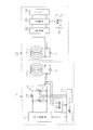
- the primary resonance coil 13 b is connected to the high frequency power supply 11 through the matching unit 12.
- the secondary resonance coil 31 b is connected to the rectifier 32. That is, the primary side coil 13 is configured by only the primary side resonance coil 13b without including the primary coil 13a as the induction coil, and the secondary side coil 31 is not provided with the secondary coil 31a as the induction coil. It is comprised only by the side resonance coil 31b.
- high-frequency power is output from the high-frequency power source 11 to the primary-side resonance coil at the resonance frequency of the resonance system, and the primary-side resonance coil 13b and the secondary-side resonance coil 13b.
- the magnetic resonance is enhanced by the side resonance coil 31b.
- the AC power output from the secondary resonance coil 31 b is rectified by the rectifier 32 and then charged to the battery 34 by the charger 33.
- FIG. 6 shows the relationship between the real part and the imaginary part of the input impedance when the output frequency is changed in the range of 50 kHz to 200 kHz and the input impedance of the resonance system is measured. The output frequency was changed from 50 kHz to increase by 1 kHz.
- a point indicated by Ps corresponds to an output frequency of 50 kHz
- a point indicated by Pe corresponds to an output frequency of 200 kHz.
- the input impedance of the resonance system does not simply change in response to an increase in the output frequency of the high-frequency power supply, but when the frequency is 50 kHz to 114 kHz, the real part of the input impedance and The imaginary part increased, and thereafter, up to a frequency of 121 kHz, the real part of the input impedance increased and the imaginary part decreased as the frequency increased.
- the real and imaginary parts of the input impedance decrease, the real part decreases and the imaginary part increases, the real and imaginary parts increase, and the real part increases.
- the imaginary part is reduced, the real part and the imaginary part are both reduced, and the real part is reduced and the imaginary part is increased.
- the input impedance Z 1 at the point indicated by f 1 is substantially equal to the input impedance Z 2 at the point indicated by f 2 .
- FIG. 7 shows the result of measuring the power transmission efficiency at each frequency by changing the output frequency of the high frequency power source in the range of 50 kHz to 200 kHz.
- Power transmission efficiency in the resonant system from FIG. 7 is the maximum frequency 140kHz become (98.80%) is the resonant frequency f o of the resonant system.
- the resonance frequency f o (140 kHz) is a value between f 1 (123 kHz) and f 2 (171 kHz), and satisfies the relationship f 1 ⁇ f o ⁇ f 2 .
- the output frequency of the high-frequency power is varied in a range of 50 kHz ⁇ 200kHz measures power transmission efficiency at each frequency
- the value of the resonant frequency f o can be confirmed by measuring the power transmission efficiency at each frequency by the output frequency of the high-frequency power was varied in a range of frequencies f 1 ⁇ f 2.
- the following effects can be obtained in addition to the effects basically the same as the effects (1), (2), and (4) of the first embodiment.
- the number of coils constituting the resonance system is one for both the power supply facility 10 and the power reception facility 30, it is possible to reduce the size of the resonance system, and to secure a mounting space when the power reception facility 30 is mounted on a vehicle. It becomes easy and the degree of freedom of the mounting position increases.
- Embodiments are not limited to the above-described embodiments, and may be embodied as follows, for example.
- ⁇ output frequency f o of the high frequency power source 11 is not limited to the resonant frequency of the resonant system, to the extent to achieve the desired performance (power transmission efficiency) as resonance type non-contact power supply system, even if some deviation value from the resonant frequency Good.
- the primary coil 13a, the primary side resonance coil 13b, the secondary coil 31a, and the secondary side resonance coil 31b are not essential, and both the primary coil 13a and the secondary coil 31a as induction coils may be omitted as in the second embodiment. Moreover, you may abbreviate
- the configuration including all of the primary coil 13a, the primary side resonance coil 13b, the secondary coil 31a, and the secondary side resonance coil 31b is easier to adjust to the matching state.
- the power supply unit is not limited to a high-frequency power supply, and may be one that converts and outputs the frequency of AC power supplied from a commercial power supply, for example.
- the impedance measuring means 14 is not limited to the configuration for measuring the input impedance of the primary side coil 13, and may be configured to measure the impedance at the input end of the matching unit 12.
- the matching unit 12 constitutes a part of the resonance system. Therefore, the matching device 12 can adjust the impedance of the resonance system, and adjusting the matching device 12 suppresses a change in the impedance of the resonance system.
- the resonance-type non-contact charging system may not include the impedance measuring means 14. In that case, resonance type impedance measurement at the time of designing and manufacturing the resonance type non-contact charging system is performed using an external power measuring device and phase measuring device.
- the output frequency f o of the power supply unit is not a resonance frequency of the resonant system, it is sufficient in the range of frequencies f 2n-1 ⁇ f o ⁇ frequency f 2n. If the range of the output frequency f o is the frequency f 2n-1 ⁇ f o ⁇ frequency f 2n of the power supply unit, the power transmission efficiency is higher than other frequencies.
- a DC / DC converter may be provided between the charger 33 and the rectifier 32, and the duty of the DC / DC converter may be controlled based on the measurement result of the impedance measuring means 14.
- a power supply unit that can output an output frequency that is the resonance frequency of the resonance system may be set.
- a matching unit may also be provided in the power receiving facility 30.
- a matching device may be provided between the secondary coil 31a and the rectifier 32, and the vehicle-side controller 35 may adjust the matching device.
- a matching unit is provided in both the power supply facility 10 and the power reception facility 30. Is preferred.
- ⁇ Matching device 12 may be provided only on the secondary side (power receiving equipment 30 side). Moreover, it is good also as a structure which does not provide the matching device 12 in any of a primary side (power supply equipment 10 side) and a secondary side (power receiving equipment 30 side).
- the rectifier 32 may be built in the charger 33.
- the battery 34 may be directly charged after the AC current output from the secondary coil 31 is rectified by the rectifier 32.
- the matching unit 12 is not limited to the configuration including the two variable capacitors 16 and 17 and the inductor 18.
- the matching unit 12 includes a variable inductor as the inductor 18 or a configuration including a variable inductor and two non-variable capacitors. Also good.
- a matching device with a non-variable configuration may be adopted as the matching device.
- a power factor correction circuit may be provided instead of the matching unit.
- a phase difference measuring unit phase difference measuring unit is provided instead of the impedance measuring unit 14.
- the vehicle as a moving body is not limited to a vehicle that requires a driver, and may be an automated guided vehicle.
- the resonance-type contactless charging system is not limited to a system that performs contactless charging to the battery 34 mounted on the vehicle.
- a system that performs non-contact charging on a battery mounted on a mobile body such as a ship or a self-propelled robot, or a battery mounted on a portable electronic device such as a mobile phone or a portable personal computer. Also good.
- the resonance-type non-contact power supply system is not limited to the resonance-type non-contact charging system, and may be applied to a device that supplies electric power to an electric device equipped on a moving body such as a robot.
- Resonance-type non-contact power supply system is moved to a work position determined by transfer means (transfer unit) such as a conveyor driven by normal power without receiving non-contact power transmission as a power source, and constant power It is good also as a structure equipped with the power receiving equipment 30 in the apparatus provided with the motor driven by 1 as a load.
- transfer means transfer unit
- the diameters of the primary coil 13a and the secondary coil 31a are not limited to the same configuration as the diameters of the primary resonance coil 13b and the secondary resonance coil 31b, and may be small or large.
- the primary-side resonance coil 13b and the secondary-side resonance coil 31b are not limited to a plurality of turns, and a coil having a turn number of 1 may be used.
- Capacitor C connected to primary side resonance coil 13b and secondary side resonance coil 31b may be omitted.
- the configuration in which the capacitor C is connected can lower the resonance frequency compared to the case where the capacitor C is omitted.
- the resonance frequency is the same, the primary resonance coil 13b and the secondary resonance coil 31b can be downsized compared to the case where the capacitor C is omitted.
- the power supply facility includes an impedance measurement unit that measures an input impedance of the resonance system, and based on a measurement result of the impedance measurement unit, an input impedance of the resonance system; Matching device control means for adjusting the matching device so as to perform matching with the impedance viewed from the input end of the resonance system to the power supply unit side is provided.
- the power receiving facility includes a rectifier, a charger, and a battery as the load.
- the power receiving equipment is provided in a vehicle.
- the output frequency of the high-frequency power supply is a condition that is allowed to be used by the Radio Law. Meet.
Landscapes
- Engineering & Computer Science (AREA)
- Power Engineering (AREA)
- Computer Networks & Wireless Communication (AREA)
- Transportation (AREA)
- Mechanical Engineering (AREA)
- Signal Processing (AREA)
- Chemical & Material Sciences (AREA)
- Chemical Kinetics & Catalysis (AREA)
- Electrochemistry (AREA)
- General Chemical & Material Sciences (AREA)
- Manufacturing & Machinery (AREA)
- Charge And Discharge Circuits For Batteries Or The Like (AREA)
- Electric Propulsion And Braking For Vehicles (AREA)
- Current-Collector Devices For Electrically Propelled Vehicles (AREA)
Abstract
L'invention concerne un système à résonance dans lequel l'alimentation électrique est fournie par une unité d'alimentation électrique configurée par au moins une bobine de résonance de côté primaire, une bobine de résonance de côté secondaire et une charge. La fréquence de sortie (f0) de l'unité d'alimentation électrique est réglée à une plage parmi des plages de fréquence f1 ≤ f0≤ fréquence f2, fréquence f3≤f0≤ fréquence f4,..., fréquence f2n-1 ≤ f0 ≤ fréquence f2n. Les fréquences f1, f2, f3, f4..., f2n-1, f2n (f1 < f2 < f3 <... < f2n-1 < f2n) sont des fréquences qui font que Z1 = Z2, Z3 = Z4,..., Z2n-1 = Z2n quand l'impédance d'entrée du système à résonance lorsque l'alimentation de ladite fréquence est fournie au système à résonance est Z1, Z2, Z3,..., Z2n-1, Z2n.
Priority Applications (4)
| Application Number | Priority Date | Filing Date | Title |
|---|---|---|---|
| JP2013520476A JP5751327B2 (ja) | 2011-06-17 | 2012-05-11 | 共鳴型非接触給電システム |
| CN201280028769.3A CN103608997A (zh) | 2011-06-17 | 2012-05-11 | 共振型非接触供电系统 |
| EP12800731.7A EP2722966A4 (fr) | 2011-06-17 | 2012-05-11 | Système d'alimentation électrique sans contact de type résonance |
| US14/125,795 US9577715B2 (en) | 2011-06-17 | 2012-05-11 | Resonance-type non-contact power supply system |
Applications Claiming Priority (2)
| Application Number | Priority Date | Filing Date | Title |
|---|---|---|---|
| JP2011135390 | 2011-06-17 | ||
| JP2011-135390 | 2011-06-17 |
Publications (1)
| Publication Number | Publication Date |
|---|---|
| WO2012172900A1 true WO2012172900A1 (fr) | 2012-12-20 |
Family
ID=47356895
Family Applications (1)
| Application Number | Title | Priority Date | Filing Date |
|---|---|---|---|
| PCT/JP2012/062180 Ceased WO2012172900A1 (fr) | 2011-06-17 | 2012-05-11 | Système d'alimentation électrique sans contact de type résonance |
Country Status (5)
| Country | Link |
|---|---|
| US (1) | US9577715B2 (fr) |
| EP (1) | EP2722966A4 (fr) |
| JP (1) | JP5751327B2 (fr) |
| CN (1) | CN103608997A (fr) |
| WO (1) | WO2012172900A1 (fr) |
Cited By (2)
| Publication number | Priority date | Publication date | Assignee | Title |
|---|---|---|---|---|
| CN103414261A (zh) * | 2013-09-06 | 2013-11-27 | 中国矿业大学(北京) | 变耦合系数磁共振无线电能传输系统及方法 |
| EP3136542A4 (fr) * | 2014-04-23 | 2017-07-05 | Panasonic Intellectual Property Management Co., Ltd. | Dispositif de transmission de puissance sans contact, dispositif de réception de puissance sans contact, et système de transmission de puissance sans contact |
Families Citing this family (8)
| Publication number | Priority date | Publication date | Assignee | Title |
|---|---|---|---|---|
| WO2012172899A1 (fr) * | 2011-06-17 | 2012-12-20 | 株式会社 豊田自動織機 | Système d'alimentation électrique sans contact de type à résonance |
| JP5751327B2 (ja) | 2011-06-17 | 2015-07-22 | 株式会社豊田自動織機 | 共鳴型非接触給電システム |
| JP6016596B2 (ja) * | 2011-12-07 | 2016-10-26 | 株式会社半導体エネルギー研究所 | 非接触給電システム |
| JP6200167B2 (ja) * | 2013-02-27 | 2017-09-20 | デクセリアルズ株式会社 | 受電装置、受電電力調整方法、受電電力調整プログラム、及び半導体装置 |
| US10075025B2 (en) * | 2013-06-19 | 2018-09-11 | Renesas Electronics Corporation | Power transmission device, wireless power feeding system, and control method |
| US20160241159A1 (en) * | 2013-10-31 | 2016-08-18 | Mitsubishi Electric Engineering Company, Limited | Resonant type high frequency power supply device |
| JP6315382B2 (ja) | 2013-12-19 | 2018-04-25 | パナソニックIpマネジメント株式会社 | 無線電力伝送のための送電装置および受電装置ならびに無線電力伝送システム |
| CN109995150A (zh) * | 2019-03-19 | 2019-07-09 | 华中科技大学 | 一种中距离无线输电系统及其高频电源 |
Citations (3)
| Publication number | Priority date | Publication date | Assignee | Title |
|---|---|---|---|---|
| JP2005184526A (ja) * | 2003-12-19 | 2005-07-07 | Ntt Docomo Inc | アンテナ装置 |
| JP2010041558A (ja) * | 2008-08-07 | 2010-02-18 | Yokohama National Univ | インピーダンス整合装置、およびインピーダンス整合方法 |
| JP2010114964A (ja) * | 2008-11-04 | 2010-05-20 | Toyota Industries Corp | 非接触電力伝送装置及びその設計方法 |
Family Cites Families (13)
| Publication number | Priority date | Publication date | Assignee | Title |
|---|---|---|---|---|
| JP4192775B2 (ja) | 2003-12-05 | 2008-12-10 | 株式会社ダイフク | 無接触給電設備 |
| JP4328705B2 (ja) * | 2004-02-27 | 2009-09-09 | 均 北吉 | Rfidタグ装置 |
| KR101118710B1 (ko) | 2005-07-12 | 2012-03-13 | 메사추세츠 인스티튜트 오브 테크놀로지 | 무선 비-방사성 에너지 전달 |
| EP1978507A4 (fr) | 2006-01-27 | 2012-06-20 | Brother Ind Ltd | Dispositif d'affichage |
| FR2920927B1 (fr) | 2007-09-11 | 2011-05-06 | Commissariat Energie Atomique | Procede d'adaptation automatique d'impedance de circuit radiofrequence et chaine d'emission ou reception a adaptation automatique |
| JP4911148B2 (ja) | 2008-09-02 | 2012-04-04 | ソニー株式会社 | 非接触給電装置 |
| US8461720B2 (en) * | 2008-09-27 | 2013-06-11 | Witricity Corporation | Wireless energy transfer using conducting surfaces to shape fields and reduce loss |
| JP4759610B2 (ja) * | 2008-12-01 | 2011-08-31 | 株式会社豊田自動織機 | 非接触電力伝送装置 |
| KR101248453B1 (ko) | 2008-12-09 | 2013-04-01 | 도요타지도샤가부시키가이샤 | 비접촉 전력 전송 장치 및 비접촉 전력 전송 장치에 있어서의 전력 전송 방법 |
| JP5585098B2 (ja) * | 2009-03-06 | 2014-09-10 | 日産自動車株式会社 | 非接触電力供給装置及び方法 |
| JP5459058B2 (ja) * | 2009-11-09 | 2014-04-02 | 株式会社豊田自動織機 | 共鳴型非接触電力伝送装置 |
| JP5751327B2 (ja) | 2011-06-17 | 2015-07-22 | 株式会社豊田自動織機 | 共鳴型非接触給電システム |
| WO2012172899A1 (fr) | 2011-06-17 | 2012-12-20 | 株式会社 豊田自動織機 | Système d'alimentation électrique sans contact de type à résonance |
-
2012
- 2012-05-11 JP JP2013520476A patent/JP5751327B2/ja not_active Expired - Fee Related
- 2012-05-11 WO PCT/JP2012/062180 patent/WO2012172900A1/fr not_active Ceased
- 2012-05-11 EP EP12800731.7A patent/EP2722966A4/fr not_active Withdrawn
- 2012-05-11 CN CN201280028769.3A patent/CN103608997A/zh active Pending
- 2012-05-11 US US14/125,795 patent/US9577715B2/en not_active Expired - Fee Related
Patent Citations (3)
| Publication number | Priority date | Publication date | Assignee | Title |
|---|---|---|---|---|
| JP2005184526A (ja) * | 2003-12-19 | 2005-07-07 | Ntt Docomo Inc | アンテナ装置 |
| JP2010041558A (ja) * | 2008-08-07 | 2010-02-18 | Yokohama National Univ | インピーダンス整合装置、およびインピーダンス整合方法 |
| JP2010114964A (ja) * | 2008-11-04 | 2010-05-20 | Toyota Industries Corp | 非接触電力伝送装置及びその設計方法 |
Non-Patent Citations (2)
| Title |
|---|
| See also references of EP2722966A4 * |
| TAKEHIRO IMURA, HIROYUKI OKABE ET AL.: "Study of Magnetic and Electric Coupling for Contactless Power Transfer Using Equivalent Circuits", IEEJ TRANSACTIONS ON INDUSTRY APPLICATIONS, DENGAKURON D, vol. 130, no. 1, January 2010 (2010-01-01), pages 84 - 88, XP008172698 * |
Cited By (2)
| Publication number | Priority date | Publication date | Assignee | Title |
|---|---|---|---|---|
| CN103414261A (zh) * | 2013-09-06 | 2013-11-27 | 中国矿业大学(北京) | 变耦合系数磁共振无线电能传输系统及方法 |
| EP3136542A4 (fr) * | 2014-04-23 | 2017-07-05 | Panasonic Intellectual Property Management Co., Ltd. | Dispositif de transmission de puissance sans contact, dispositif de réception de puissance sans contact, et système de transmission de puissance sans contact |
Also Published As
| Publication number | Publication date |
|---|---|
| CN103608997A (zh) | 2014-02-26 |
| US9577715B2 (en) | 2017-02-21 |
| JP5751327B2 (ja) | 2015-07-22 |
| EP2722966A1 (fr) | 2014-04-23 |
| EP2722966A4 (fr) | 2015-09-09 |
| US20140175897A1 (en) | 2014-06-26 |
| JPWO2012172900A1 (ja) | 2015-02-23 |
Similar Documents
| Publication | Publication Date | Title |
|---|---|---|
| JP5751327B2 (ja) | 共鳴型非接触給電システム | |
| US9287719B2 (en) | Power supply side equipment and resonance-type non-contact power supply system | |
| JP5751326B2 (ja) | 共鳴型非接触給電システム | |
| JP5457552B2 (ja) | 共鳴型非接触給電システム、および共鳴型非接触給電システムの充電時における整合器の調整方法 | |
| JP5459058B2 (ja) | 共鳴型非接触電力伝送装置 | |
| WO2011093292A1 (fr) | Système de transmission d'énergie sans contact et appareil de transmission d'énergie sans contact | |
| JP2012060807A (ja) | 給電装置、受電装置およびそれを備える車両、ならびに給電システムの制御方法 | |
| WO2013084754A1 (fr) | Dispositif de transmission de puissance électrique sans contact | |
| JP2011155733A (ja) | 非接触送電システム、および非接触送電装置 | |
| JP6535003B2 (ja) | 無線電力受信装置 | |
| CN103068618A (zh) | 谐振型非接触电力供应系统 | |
| WO2013183700A1 (fr) | Dispositif de réception de puissance et système d'émission de puissance sans contact | |
| WO2014007352A1 (fr) | Dispositif de transmission et dispositif de transmission d'énergie électrique sans contact | |
| WO2014054395A1 (fr) | Dispositif d'émission de puissance, dispositif de réception de puissance et appareil de transfert de puissance sans contact | |
| JP5991380B2 (ja) | 非接触電力伝送装置 | |
| JP2015195675A (ja) | 電力伝送システム | |
| JP2012257374A (ja) | 非接触電力伝送装置 | |
| WO2015098747A1 (fr) | Dispositif de transmission d'énergie et appareil de transmission d'énergie sans contact | |
| WO2014030689A1 (fr) | Dispositif de transmission de puissance sans contact et appareil de réception de puissance | |
| JP2013165617A (ja) | 非接触給電装置及びそれを用いた非接触給電システム | |
| WO2013183701A1 (fr) | Appareil de réception de puissance, appareil d'émission de puissance, et dispositif d'émission de puissance sans contact | |
| JP2016208602A (ja) | 非接触電力伝送装置 |
Legal Events
| Date | Code | Title | Description |
|---|---|---|---|
| 121 | Ep: the epo has been informed by wipo that ep was designated in this application |
Ref document number: 12800731 Country of ref document: EP Kind code of ref document: A1 |
|
| ENP | Entry into the national phase |
Ref document number: 2013520476 Country of ref document: JP Kind code of ref document: A |
|
| NENP | Non-entry into the national phase |
Ref country code: DE |
|
| WWE | Wipo information: entry into national phase |
Ref document number: 14125795 Country of ref document: US |