WO2012173349A2 - 무선 통신 시스템에서 전력 절감 모드 내에서 데이터 전송 방법 및 장치 - Google Patents
무선 통신 시스템에서 전력 절감 모드 내에서 데이터 전송 방법 및 장치 Download PDFInfo
- Publication number
- WO2012173349A2 WO2012173349A2 PCT/KR2012/004392 KR2012004392W WO2012173349A2 WO 2012173349 A2 WO2012173349 A2 WO 2012173349A2 KR 2012004392 W KR2012004392 W KR 2012004392W WO 2012173349 A2 WO2012173349 A2 WO 2012173349A2
- Authority
- WO
- WIPO (PCT)
- Prior art keywords
- base station
- data
- traffic
- ranging
- mode
- Prior art date
- Legal status (The legal status is an assumption and is not a legal conclusion. Google has not performed a legal analysis and makes no representation as to the accuracy of the status listed.)
- Ceased
Links
Images




Classifications
-
- H—ELECTRICITY
- H04—ELECTRIC COMMUNICATION TECHNIQUE
- H04W—WIRELESS COMMUNICATION NETWORKS
- H04W60/00—Affiliation to network, e.g. registration; Terminating affiliation with the network, e.g. de-registration
- H04W60/06—De-registration or detaching
-
- Y—GENERAL TAGGING OF NEW TECHNOLOGICAL DEVELOPMENTS; GENERAL TAGGING OF CROSS-SECTIONAL TECHNOLOGIES SPANNING OVER SEVERAL SECTIONS OF THE IPC; TECHNICAL SUBJECTS COVERED BY FORMER USPC CROSS-REFERENCE ART COLLECTIONS [XRACs] AND DIGESTS
- Y02—TECHNOLOGIES OR APPLICATIONS FOR MITIGATION OR ADAPTATION AGAINST CLIMATE CHANGE
- Y02D—CLIMATE CHANGE MITIGATION TECHNOLOGIES IN INFORMATION AND COMMUNICATION TECHNOLOGIES [ICT], I.E. INFORMATION AND COMMUNICATION TECHNOLOGIES AIMING AT THE REDUCTION OF THEIR OWN ENERGY USE
- Y02D30/00—Reducing energy consumption in communication networks
- Y02D30/70—Reducing energy consumption in communication networks in wireless communication networks
Definitions
- the present invention relates to wireless communication, and more particularly, to a data transmission method and apparatus in a power saving mode in a wireless communication system.
- the Institute of Electrical and Electronics Engineers (IEEE) 802.16e standard is the sixth standard for international mobile telecommunications (IMT-2000) in the ITU-radiocommunication sector (ITU-R) under the International Telecommunication Union (ITU) in 2007. It was adopted under the name OFDMA TDD '. ITU-R is preparing the IMT-advanced system as the next generation 4G mobile communication standard after IMT-2000.
- the IEEE 802.16 working group (WG) decided to pursue the IEEE 802.16m project with the goal of drafting an amendment standard of the existing IEEE 802.16e as a standard for the IMT-advanced system at the end of 2006.
- the IEEE 802.16m standard implies two aspects: past continuity of modification of the IEEE 802.16e standard and future continuity of the specification for next generation IMT-advanced systems. Therefore, the IEEE 802.16m standard is required to satisfy all the advanced requirements for the IMT-advanced system while maintaining compatibility with the mobile WiMAX system based on the IEEE 802.16e standard.
- the IEEE 802.16p specification which is based on the IEEE 802.16e standard and the IEEE 802.16m standard and optimized for machine-to-machine communication (M2M), is being developed.
- M2M communication may be defined as an information exchange performed between a subscriber station and a server or between subscriber stations in a core network without any interaction with a person. .
- a device that performs M2M communication may be referred to as an M2M device.
- the IEEE 802.16p specification is the minimum change in orthogonal frequency division multiple access (OFDMA) physical layer (PHY) within the enhancement of medium access control (MAC) and licensed bands of the IEEE 802.16 specification. Is under discussion. As the IEEE 802.16p specification is discussed, wide area wireless coverage is required within the licensed band, and the scope of application of automated M2M communications for the purpose of observation and control is wide. Can lose.
- OFDMA orthogonal frequency division multiple access
- PHY physical layer
- MAC medium access control
- M2M applications have significantly different requirements for network access, typically human-initiated or human-controlled network access. Require. M2M applications include vehicular telematics for vehicles, healthcare monitoring of bio-sensors, remote maintenance and control, smart metering, and consumer devices Automated services, etc. M2M application requirements include very lower power consumption, large numbers of devices, short bursts, etc. transmission, device tampering detection and reporting, improved device authentication, and the like.
- the operation of the M2M device may be optimized.
- a power saving mode for entering each M2M device may be determined according to mobility, communication type, and scheduling type of the M2M device. Even in the power saving mode, there may be data to be transmitted by the base station or the M2M device. Whenever there is data to be sent, it may be inefficient to exit the power saving mode and perform network reentry.
- An object of the present invention is to provide a data transmission method and apparatus in a power saving mode in a wireless communication system.
- the present invention provides a method of transmitting uplink data while maintaining a DCR mode when an M2M device in a delegation with context retention (DCR) mode transmits uplink data.
- DCR delegation with context retention
- a data transmission method by a machine-to-machine (M2M) device in a deregistration with context retention (DCR) mode in a wireless communication system generates uplink (UL) data having a size smaller than 140 bytes, and transmits a ranging request message (AAI-RNG-REQ) including the UL data to a base station.
- UL uplink
- AI-RNG-REQ ranging request message
- the ranging request message may further include a context retention identifier (CRID) which is an M2M device identifier currently assigned to the M2M device in the DCR mode.
- CRID context retention identifier
- the ranging response message may further include a traffic indication field indicating whether there is downlink (DL) data to be transmitted from the base station to the M2M device in the DCR mode.
- DL downlink
- the data transmission method may further include terminating the DCR mode by performing network reentry to the base station and receiving the DL data from the base station.
- the value of the traffic indication field is 1, and the traffic indication field may indicate that there is DL data to be transmitted by the base station to the M2M device.
- the ranging response message may further include a DL traffic start time field indicating a least significant bit (LSB) 8 bits of a frame number at which the base station starts to transmit the DL data. Can be.
- LSB least significant bit
- the data transmission method may further include receiving the DL data from the base station without terminating the DCR mode.
- the last DL data of the DL data transmitted by the base station may include a multicast traffic end extended header (MTEEH) or a traffic end extended header (TEEH).
- MBEH multicast traffic end extended header
- TEEH traffic end extended header
- the DCR mode may be determined based on an M2M power saving class negotiated with the base station at the time of network entry.
- the data transmission method may further include receiving a CRID of the M2M device from the base station upon entering the network.
- a machine-to-machine (M2M) device is provided that is in a derivative with context retention (DCR) mode in a wireless communication system.
- the M2M device includes a radio frequency (RF) unit for transmitting or receiving a radio signal, and a processor connected to the RF unit, wherein the processor is uplink (UL) data having a size smaller than 140 bytes.
- RF radio frequency
- UL uplink
- AAI-RNG-REQ ranging request message
- AI-RNG-RSP ranging response message
- the ranging request message includes a ranging purpose indication field indicating a location update for transmitting the UL data in the DCR mode
- the ranging response message includes: a ranging purpose indication field
- the message is a location update response indicating a success of a location update for transmission of the UL data in response to the ranging purpose indication field. se) contains fields.
- UL data can be efficiently transmitted to the base station without performing network re-entry.
- 1 illustrates a wireless communication system
- M2M machine-to-machine
- FIG 3 illustrates an advanced M2M service system structure of IEEE 802.16 supporting M2M communication.
- FIG. 4 shows an example of a frame structure of IEEE 802.16m.
- FIG 6 shows an embodiment of the proposed multicast traffic reception method.
- FIG 10 shows another embodiment of the proposed multicast traffic reception method.
- 11 shows another embodiment of the proposed multicast traffic reception method.
- 16 is a block diagram of a wireless communication system in which an embodiment of the present invention is implemented.
- CDMA code division multiple access
- FDMA frequency division multiple access
- TDMA time division multiple access
- OFDMA orthogonal frequency division multiple access
- SC-FDMA single carrier frequency division multiple access
- CDMA may be implemented by a radio technology such as universal terrestrial radio access (UTRA) or CDMA2000.
- TDMA may be implemented with wireless technologies such as global system for mobile communications (GSM) / general packet radio service (GPRS) / enhanced data rates for GSM evolution (EDGE).
- GSM global system for mobile communications
- GPRS general packet radio service
- EDGE enhanced data rates for GSM evolution
- OFDMA may be implemented in a wireless technology such as IEEE 802.11 (Wi-Fi), IEEE 802.16 (WiMAX), IEEE 802-20, evolved UTRA (E-UTRA).
- IEEE 802.16m is an evolution of IEEE 802.16e and provides backward compatibility with systems based on IEEE 802.16e.
- UTRA is part of a universal mobile telecommunications system (UMTS).
- 3rd generation partnership project (3GPP) long term evolution (LTE) is part of evolved UMTS (E-UMTS) using evolved-UMTS terrestrial radio access (E-UTRA), which employs OFDMA in downlink and SC in uplink -FDMA is adopted.
- LTE-A evolution of 3GPP LTE.
- 1 illustrates a wireless communication system
- the wireless communication system 10 includes at least one base station (BS) 11.
- Each base station 11 provides a communication service for a particular geographic area (generally called a cell) 15a, 15b, 15c.
- the cell can in turn be divided into a number of regions (called sectors).
- a user equipment (UE) 12 may be fixed or mobile, and may include a mobile station (MS), a mobile terminal (MS), a user terminal (UT), a subscriber station (SS), a wireless device, and a PDA (PDA). It may be called other terms such as personal digital assistant, wireless modem, handheld device, etc.
- Base station 11 generally refers to a fixed station that communicates with terminal 12, It may be called other terms such as an evolved-NodeB (eNB), a base transceiver system (BTS), an access point, and the like.
- eNB evolved-NodeB
- BTS base transceiver system
- access point and the like.
- the UE belongs to one cell, and the cell to which the UE belongs is called a serving cell.
- a base station that provides a communication service for a serving cell is called a serving BS. Since the wireless communication system is a cellular system, there are other cells adjacent to the serving cell. Another cell adjacent to the serving cell is called a neighbor cell.
- a base station that provides communication service for a neighbor cell is called a neighbor BS.
- the serving cell and the neighbor cell are relatively determined based on the terminal.
- downlink means communication from the base station 11 to the terminal 12
- uplink means communication from the terminal 12 to the base station 11.
- the transmitter may be part of the base station 11 and the receiver may be part of the terminal 12.
- the transmitter may be part of the terminal 12 and the receiver may be part of the base station 11.
- M2M machine-to-machine
- the basic M2M service system architecture 20 may include a mobile network operator (MNO) 21, an M2M service consumer 24, at least one IEEE 802.16 M2M device (hereinafter, 802.16 M2M device, 28), at least One non-IEEE 802.16 M2M device 29 is included.
- the MNO 21 includes an access service network (ASN) and a connectivity service network (CSN).
- the 802.16 M2M device 28 is an IEEE 802.16 terminal with M2M functionality.
- the M2M server 23 is an entity that communicates with one or more 802.16 M2M devices 28.
- the M2M server 23 has an interface to which the M2M service consumer 24 can connect.
- the M2M service consumer 24 is a user of the M2M service.
- the M2M server 23 may be inside or outside a connectivity service network (CSN) and may provide specific M2M services to one or more 802.16 M2M devices 28.
- the ASN may include an IEEE 802.16 base station 22.
- the M2M application is operated based on the 802.16 M2M device 28 and the M2M server 23.
- the basic M2M service system architecture 20 supports two kinds of M2M communication: M2M communication between one or more 802.16 M2M devices and an M2M server or point-to-multipoint communication between 802.16 M2M devices and an IEEE 802.16 base station. do.
- the basic M2M service system architecture of FIG. 2 allows an 802.16 M2M device to act as an aggregation point for a non-IEEE 802.16 M2M device.
- Non-IEEE 802.16 M2M devices use a wireless interface different from IEEE 802.16, such as IEEE 802.11, IEEE 802.15 or PLC. At this time, the change of the air interface of the non-IEEE 802.16 M2M device to IEEE 802.16 is not allowed.
- FIG 3 illustrates an advanced M2M service system structure of IEEE 802.16 supporting M2M communication.
- an 802.16 M2M device may operate as an aggregation point for a non-IEEE 802.16 M2M device and may also operate as an aggregation point for an 802.16 M2M device.
- the wireless interface may be changed to IEEE 802.16 in order to perform the aggregation function for the 802.16 M2M device and the non-802.16 M2M device.
- an enhanced M2M service system architecture may support peer-to-peer (P2P) connectivity between 802.16 M2M devices, where the P2P connection may be over IEEE 802.16 or over another wireless interface such as IEEE 802.11, IEEE 802.15 or PLC. Can be connected.
- P2P peer-to-peer
- FIG. 4 shows an example of a frame structure of IEEE 802.16m.
- a superframe includes a superframe header (SFH) and four frames (frames, F0, F1, F2, and F3).
- Each frame in the superframe may have the same length.
- the size of each superframe is 20ms and the size of each frame is illustrated as 5ms, but is not limited thereto.
- the length of the superframe, the number of frames included in the superframe, the number of subframes included in the frame, and the like may be variously changed.
- the number of subframes included in the frame may be variously changed according to channel bandwidth and length of a cyclic prefix (CP).
- CP cyclic prefix
- One frame includes a plurality of subframes (subframe, SF0, SF1, SF2, SF3, SF4, SF5, SF6, SF7). Each subframe may be used for uplink or downlink transmission.
- One subframe includes a plurality of orthogonal frequency division multiplexing (OFDM) symbols or an orthogonal frequency division multiple access (OFDMA) in a time domain, and includes a plurality of subcarriers in the frequency domain. do.
- the OFDM symbol is used to represent one symbol period, and may be called another name such as an OFDMA symbol or an SC-FDMA symbol according to a multiple access scheme.
- the subframe may be composed of 5, 6, 7 or 9 OFDMA symbols, but this is only an example and the number of OFDMA symbols included in the subframe is not limited.
- the number of OFDMA symbols included in the subframe may be variously changed according to the channel bandwidth and the length of the CP.
- a type of a subframe may be defined according to the number of OFDMA symbols included in the subframe.
- the type-1 subframe may be defined to include 6 OFDMA symbols
- the type-2 subframe includes 7 OFDMA symbols
- the type-3 subframe includes 5 OFDMA symbols
- the type-4 subframe includes 9 OFDMA symbols.
- One frame may include subframes of the same type. Alternatively, one frame may include different types of subframes.
- the number of OFDMA symbols included in each subframe in one frame may be the same or different.
- the number of OFDMA symbols of at least one subframe in one frame may be different from the number of OFDMA symbols of the remaining subframes in the frame.
- a TDD scheme or a frequency division duplex (FDD) scheme may be applied to the frame.
- each subframe is used for uplink transmission or downlink transmission at different times at the same frequency. That is, subframes in a frame of the TDD scheme are classified into an uplink subframe and a downlink subframe in the time domain.
- each subframe is used for uplink transmission or downlink transmission at different frequencies at the same time. That is, subframes in the frame of the FDD scheme are divided into an uplink subframe and a downlink subframe in the frequency domain. Uplink transmission and downlink transmission occupy different frequency bands and may be simultaneously performed.
- the SFH may carry essential system parameters and system configuration information.
- the SFH may be located in the first subframe in the superframe.
- SFH may occupy the last five OFDMA symbols of the first subframe.
- the superframe header may be classified into primary SFH (P-SFH) and secondary SFH (S-SFH; secondary-SFH).
- P-SFH primary SFH
- S-SFH secondary SFH
- the P-SFH may be transmitted every superframe.
- Information transmitted to the S-SFH can be divided into three subpackets (S-SFH SP1, S-SFH SP2, S-SFH SP3). Each subpacket may be transmitted periodically with a different period. The importance of information transmitted through S-SFH SP1, S-SFH SP2, and S-SFH SP3 may be different from each other.
- S-SFH SP1 may be transmitted in the shortest period, and S-SFH SP3 may be transmitted in the longest period.
- S-SFH SP1 includes information on network re-entry, and the transmission period of S-SFH SP1 may be 40 ms.
- S-SFH SP2 includes information about initial network entry and network discovery, and the transmission period of S-SFH SP2 may be 80 ms.
- S-SFH SP3 includes the remaining important system information, and the transmission period of S-SFH SP3 may be either 160 ms or 320 ms.
- One OFDMA symbol includes a plurality of subcarriers, and the number of subcarriers is determined according to the FFT size.
- the types of subcarriers can be divided into data subcarriers for data transmission, pilot subcarriers for various measurements, guard bands and null carriers for DC carriers.
- Parameters that characterize an OFDMA symbol are BW, N used , n, G, and the like.
- BW is the nominal channel bandwidth.
- N used is the number of subcarriers used (including DC subcarriers).
- n is a sampling factor. This parameter is combined with BW and N used to determine subcarrier spacing and useful symbol time.
- G is the ratio of CP time to useful time.
- Table 1 below shows OFDMA parameters.
- the OFDMA parameters of Table 1 may be equally used for the frame structure of 802.16e of FIG. 4.
- T s ( ⁇ s) 102.857 144 115.2 102.857 102.857 FDD Number of ODFMA symbols per 5ms frame 48 34 43 48 48 Idle time ( ⁇ s) 62.857 104 46.40 62.857 62.857 TDD Number of ODFMA symbols per 5ms frame 47 33 42 47 47 TTG + RTG ( ⁇ s) 165.714 248 161.6 165.714 165.714 G 1/16 Symbol time, T s ( ⁇ s) 97.143 136 108.8 97.143 97.143 97.143
- the operation of the M2M device may be optimized.
- characteristics related to power saving of the M2M device may be defined according to the characteristics of the M2M device.
- a power saving mode for entering each M2M device may be determined according to mobility, communication type, and scheduling type of the M2M device.
- the power saving mode that the M2M device may enter may be either an idle mode or a degistration with context retention (DCR) mode.
- the DCR mode indicates a mode in which the terminal is deregistered from the network, but the context of the terminal is kept in the network before the context maintenance timer expires.
- a context retention identifier assigned to each terminal may be used to identify the terminal in the DCR mode.
- Table 2 shows an example of a power saving class and a power saving mode of the M2M device determined according to the mobility, communication type, and scheduling delay of the M2M device.
- M2M power saving class properties Mobility (mobility) Communication type Scheduling delay Power saving mode
- M2M PSC1 No Device originated only Tolerant DCR Mode
- M2M PSC2 No Network originated only tolerant Idle mode
- M2M PSC3 No Both originated Unbearable Idle mode
- M2M PSC4 Yes network originated only intolerant Idle mode
- M2M PSC5 Yes network originated only tolerant Idle mode
- Mobility indicates whether the M2M device is fixed or mobile.
- the communication type indicates the direction of data transmitted in the M2M communication. That is, when the communication type is 'device originated only', only traffic transmitted by the M2M device to the base station exists, and when the communication type is 'network originated only', only traffic transmitted by the base station to the M2M device exists.
- the scheduling delay indicates whether the transmitted traffic is sensitive to delay.
- the M2M power saving class defined as shown in Table 2 may be predetermined between the M2M device and the base station or another network entity, or may be determined by negotiating with the M2M device and the base station at the network entry stage.
- the power saving mode of the M2M device may be determined based on the determined M2M power saving class.
- Table 3 shows the functions required and unnecessary functions for each M2M device and the power saving mode of each M2M device based on the M2M power saving class defined by Table 2.
- M2M power saving class Explanation M2M PSC 1 Only when there is no mobility and the M2M device has data to transmit Since data is transmitted, no paging and location update procedures are required.
- Paging not supported Timer-based location update: not supported Paging group-based location update: not supported Paging Group ID, Paging Controller ID: Unassigned Deregistration ID (idle mode identifier): not used No paging cycles, paging offsets, paging listening intervals Power Saving Mode: DCR Mode M2M PSC 2 Because of its mobility, no paging group-based location update is required. Since only the base station transmits data to the M2M device, a DL notification mechanism to the M2M device is required. Therefore, paging must be supported.
- Paging Supported Timer-based location update: supported Paging group-based location update: not supported Paging Group ID: Unassigned, paging by M2M group ID (MGID) Paging Controller ID: Assigned Deregistration ID: Used (M2M DID (device ID)) Paging Cycle, Paging Offset Allocation Power Saving Mode: Idle Mode M2M PSC 3 Because of its mobility, no paging group-based location update is required. Since the base station can transmit data to the M2M device, a DL notification mechanism to the M2M device is required. Therefore, paging must be supported.
- M2M group ID M2M group ID
- Paging Controller ID Assigned Deregistration ID: Used (M2M DID (device ID)) Paging Cycle
- Paging Offset Allocation Power Saving Mode Idle Mode M2M PSC 3 Because of its mobility, no paging group-based location update is required. Since the base station can transmit data to the M2M device, a DL notification mechanism to the M2M
- Paging Supported Timer-based location update: supported Paging group-based location update: not supported Paging Group ID: Unassigned, paging by M2M group ID (MGID) Paging Controller ID: Assigned Deregistration ID: Used (M2M DID) Paging Cycle, Paging Offset Allocation Power Saving Mode: Idle Mode M2M PSC 4 Because of its mobility, a location update procedure is required. Since the base station can transmit data to the M2M device, a DL notification mechanism to the M2M device is required. Therefore, paging must be supported.
- M2M group ID M2M group ID
- M2M DID Used (M2M DID) Paging Cycle
- Paging Offset Allocation Power Saving Mode Idle Mode M2M PSC 4 Because of its mobility, a location update procedure is required. Since the base station can transmit data to the M2M device, a DL notification mechanism to the M2M device is required. Therefore, paging must be supported.
- Paging Supported Timer-based location update: supported Paging Group-Based Location Updates: Supported Paging Group ID, Paging Controller ID: Assigned Deregistration ID: Used (M2M DID) Paging Cycle, Paging Offset Allocation Power Saving Mode: Idle Mode ... ... M2M PSC N Only when there is no mobility and the M2M device has data to transmit Since data is sent, no paging and location update procedures are required.
- Paging not supported Timer-based location update: not supported Paging group-based location update: not supported Paging Group ID, Paging Controller ID: Unassigned Deregistration ID (idle mode identifier): not used Paging Cycle, Paging Offset, No Paging Receive Interval Power Saving Mode: DCR Mode
- the DCR to the power saving mode of the M2M device Mode can be used.
- step S100 the network entity transmits a CRID (hereinafter referred to as M2M CRID) of the M2M device to the base station.
- M2M CRID a CRID
- step S101 the M2M device performs network entry to the base station.
- the M2M power saving class may be negotiated when the M2M device performs network entry, and the base station assigns the M2M CRID to the M2M device.
- DCR mode initialization is performed between the M2M device and the base station.
- DCR mode initialization may be performed in a connected mode or in an idle mode.
- the M2M device may initialize the DCR mode by transmitting a deregistration request message (AAI-DREG-REQ).
- the M2M device may request the base station to maintain specific service and operation information for the DCR mode through an AAI-DREG-REQ message.
- the base station accepts the request of the M2M device, the base station may transmit a deregistration response message (AAI-DREG-RSP) to the M2M device.
- the M2M device that receives the AAI-DREG-RSP message starts a context maintenance timer.
- the M2M device may initialize the DCR mode by performing a location update through a ranging request message (AAI-RNG-REQ).
- the base station accepts the request of the M2M device, the base station may transmit a ranging response message (AAI-RNG-RSP) to the M2M device.
- the M2M device that receives the AAI-RNG-RSP message starts a context maintenance timer. While the context hold timer is valid, the network maintains the information of the M2M device.
- step S103 the M2M device in the DCR mode generates UL data to transmit.
- step S104 network reentry is performed between the M2M device and the base station.
- optimized network reentry may be performed through the M2M CRID.
- the M2M device may initiate network reentry by transmitting an AAI-RNG-REQ message including the M2M CRID to the base station.
- step S105 the base station retrieves information of the M2M device maintained by the network using the M2M CRID.
- the DCR mode may be terminated when the M2M device re-enters the network or the context hold timer expires.
- the M2M device In the DCR mode, the M2M device does not receive the paging message and thus cannot receive the multicast traffic transmitted by the base station or the network entity. This is because the paging message includes information indicating the presence or absence of multicast traffic.
- the multicast traffic is data transmitted from the base station to the plurality of M2M devices at the same time and may include firmware upgrade related data.
- a method for M2M device to receive multicast traffic may be required.
- a multicast traffic indication extended header (MTIEH) may be newly defined.
- Table 4 shows an example of MTIEH newly defined by the present invention.
- the MTIEH includes a Response Indication field and includes a Multicast Transmission Indication field when the value of the Response Indication field is 1.
- the Multicast Transmission Indication field indicates whether there is multicast traffic to be transmitted by the base station.
- MTIEH of Table 4 indicates the presence of multicast traffic in a multicast manner, but can similarly indicate the presence of DL traffic in a unicast manner.
- TIEH traffic indication extended header
- the TIEH includes a Response Indication field
- the TIEH includes a Traffic Indication field when the value of the Response Indication field is 1.
- the Traffic Indication field indicates whether there is DL traffic to be transmitted by the base station.
- FIG 6 shows an embodiment of the proposed multicast traffic reception method.
- the M2M device may receive multicast traffic from the base station through MTIEH.
- M2M devices such as smart metering devices that only transmit the collected information to the network, periodically monitor the DL to receive multicast traffic, and do not check for the presence of multicast traffic, and the DCR mode ends.
- the UL data is transmitted, it is possible to confirm the presence of multicast traffic.
- the network entity transmits an M2M CRID to the base station.
- the M2M device performs network entry to the base station.
- the M2M power saving class may be negotiated when the M2M device performs network entry, and the base station assigns the M2M CRID to the M2M device.
- DCR mode initialization is performed between the M2M device and the base station.
- the M2M device in the DCR mode generates UL data to transmit. Accordingly, the M2M device performs network reentry to the base station.
- step S204 the M2M device transmits the MAC message with the MTIEH defined in Table 4 to the base station.
- a value of the Response Indication field in the MTIEH may be zero. That is, the Response Indication field may indicate a request.
- the base station transmits the MAC message with MTIEH to the M2M device.
- a value of the Response Indication field in the MTIEH may be 1. That is, the Response Indication field may indicate a response. Accordingly, the base station can indicate to the M2M device whether multicast traffic is present through the Multicast transmission Indication field in the MTIEH.
- step S206 the M2M device transmits the generated UL data to the base station and, if there is multicast traffic, receives the multicast traffic from the base station.
- the network entity transmits an M2M CRID to the base station.
- the M2M device performs network entry to the base station.
- the M2M power saving class may be negotiated when the M2M device performs network entry, and the base station assigns the M2M CRID to the M2M device.
- DCR mode initialization is performed between the M2M device and the base station.
- the M2M device in the DCR mode generates UL data to transmit. Accordingly, the M2M device performs network reentry to the base station.
- step S214 the base station transmits a MAC message with MTIEH to the M2M device.
- MTIEH may be defined as shown in Table 6.
- Table 6 is a variation of Table 4.
- the base station may indicate to the M2M device whether multicast traffic is present through the Multicast Traffic Indication field in the MTIEH.
- TIEH may be defined as shown in Table 7 to indicate whether DL traffic exists in a unicast manner.
- Table 7 is a variation of Table 5.
- the base station may indicate to the M2M device whether DL traffic exists through the Traffic Indication field in the TIEH.
- step S215 the M2M device transmits generated UL data to the base station, and receives multicast traffic from the base station if the multicast traffic exists.
- step S220 the network entity transmits an M2M CRID to the base station.
- the M2M device performs network entry to the base station.
- the M2M power saving class may be negotiated when the M2M device performs network entry, and the base station assigns the M2M CRID to the M2M device.
- step S222 DCR mode initialization is performed between the M2M device and the base station.
- step S223 the M2M device in the DCR mode generates UL data to be transmitted. Accordingly, the M2M device performs network reentry to the base station.
- step S224 the M2M device transmits a ranging request message (AAI-RNG-REQ) to the base station.
- step S225 the base station transmits a ranging response message (AAI-RNG-RSP) to the M2M device in response to the AAI-RNG-REQ message.
- the AAI-RNG-RSP message includes a multicast traffic indication. That is, the AAI-RNG-RSP message can inform the M2M device whether the multicast traffic is present.
- Table 8 shows an example of an AAI-RNG-RSP message including a multicast traffic indication.
- the base station may indicate to the M2M device whether multicast traffic is present through the Multicast Traffic Indication field in the AAI-RNG-RSP message.
- the AAI-RNG-RSP message may include a traffic indication in order to indicate whether DL traffic exists in a unicast manner.
- Table 9 shows an example of an AAI-RNG-RSP message including a traffic indication.
- the base station needs to inform the M2M device that it is the last multicast traffic.
- the present invention attaches a multicast traffic end extended header (MTEEH) to the last multicast traffic transmitted by the base station, and informs the M2M device that the base station is the last multicast traffic.
- MTEEH multicast traffic end extended header
- the M2M device can immediately enter the DCR mode to reduce power consumption.
- the network entity transmits an M2M CRID to the base station.
- the M2M device performs network entry to the base station.
- the M2M power saving class may be negotiated when the M2M device performs network entry, and the base station assigns the M2M CRID to the M2M device.
- DCR mode initialization is performed between the M2M device and the base station.
- the M2M device in the DCR mode generates UL data to transmit. Accordingly, the M2M device performs network reentry to the base station.
- the base station transmits the MAC message with MTIEH to the M2M device.
- the MTIEH may be defined as shown in Table 6.
- the base station may indicate to the M2M device whether multicast traffic is present through the Multicast Traffic Indication field in the MTIEH.
- the M2M device transmits the generated UL data to the base station, and receives the multicast traffic from the base station if there is multicast traffic.
- step S306 the base station transmits the MAC message including the MTEEH to the M2M device.
- MTEEH may be defined as shown in Table 10.
- a traffic end extended header similar to Table 10 may be defined as shown in Table 11 to indicate whether the last DL traffic is unicast.
- the M2M device receiving the MAC message including the MTEEH may initialize the DCR mode again.
- the M2M device transmits an AAI-DREG-REQ message to the base station, and in step S308, the base station transmits an AAI-DREG-RSP message to the M2M device in response to the AAI-DREG-REQ message.
- FIG 10 shows another embodiment of the proposed multicast traffic reception method.
- the network entity transmits an M2M CRID to the base station.
- the M2M device performs network entry to the base station.
- the M2M power saving class may be negotiated when the M2M device performs network entry, and the base station assigns the M2M CRID to the M2M device.
- DCR mode initialization is performed between the M2M device and the base station.
- the M2M device in the DCR mode generates UL data to be transmitted. Accordingly, the M2M device performs network reentry to the base station.
- the base station transmits the MAC message with MTIEH to the M2M device.
- the MTIEH may be defined as shown in Table 6.
- the base station may indicate to the M2M device whether multicast traffic is present through the Multicast Traffic Indication field in the MTIEH.
- the M2M device transmits the generated UL data to the base station and, if there is multicast traffic, receives the multicast traffic from the base station.
- the base station transmits a MAC message including MTEEH to the M2M device.
- the MAC message may further include a DCR mode reinitialization request.
- the DCR mode reinitialization request may be included in the MTEEH. That is, the base station may request the M2M device to enter the DCR mode in an unsolicited manner while indicating that the base station is the last multicast traffic.
- Table 12 shows an example of an MTEEH including an action code requesting DCR mode reinitialization.
- a TEEH including an action code for unconditionally requesting DCR mode reinitialization may be defined as shown in Table 13.
- the M2M device receiving the MTEEH including the DCR mode reinitialization request transmits an AAI-DREG-REQ message to the base station and enters the DCR mode in response.
- the AAI-DREG-REQ message may include a confirmation of the DCR mode reinitialization request of the base station.
- Table 14 shows an example of an AAI-DREG-REQ message including confirmation of a DCR mode reinitialization request of a base station.
- AAI-DREG-REQ ⁇ De-registration-Request_Code 3 Indicates the purpose of the AAI-DREG-REQ message 0x00: UE deregistration request from base station and network 0x01: UE deregistration request from S-ABS and initialization mode of idle mode of UE 0x02: Response to AAI-DREG-RSP message with action code 0x05 sent from base station 0x03: Rejection for an AAI-DREG-RSP message with an action code 0x05 sent from the base station. This code is applicable only if the terminal has UL data to transmit.
- 0x04 UE deregistration request from S-ABS to enter DCR mode
- 0x04 request for AMS
- AMS 0x05 a) response to AAI-DREG-RSP message with action code 0x00, 0x01, 0x02 or 0x03, b) response to MTEEH or TEEH including Request_DCR_Mode_Initiation field ... ⁇ - -
- the AAI-DREG-REQ message includes a De-registration-Request_code field.
- the De-registration-Request_code field may indicate a response to MTEEH or TEEH including the Request_DCR_Mode_Intiation field.
- 11 shows another embodiment of the proposed multicast traffic reception method.
- the network entity transmits an M2M CRID to the base station.
- the M2M device performs network entry to the base station.
- the M2M power saving class may be negotiated when the M2M device performs network entry, and the base station assigns the M2M CRID to the M2M device.
- DCR mode initialization is performed between the M2M device and the base station.
- the M2M device in the DCR mode generates UL data to be transmitted. Accordingly, the M2M device performs network reentry to the base station.
- the base station transmits the MAC message with MTIEH to the M2M device.
- the MTIEH may be defined as shown in Table 6.
- the base station may indicate to the M2M device whether multicast traffic is present through the Multicast Traffic Indication field in the MTIEH.
- the M2M device transmits the generated UL data to the base station, and receives the multicast traffic from the base station if there is multicast traffic.
- step S326 the base station transmits a MAC message including MTEEH to the M2M device.
- step S327 the base station transmits an AAI-DREG-RSP message to the M2M device.
- the AAI-DREG-RSP message may further include a DCR mode reinitialization request. That is, the base station may request the M2M device to enter the DCR mode unconditionally through the AAI-DREG-RSP message.
- Table 15 shows an example of an AAI-DREG-RSP message including an action code requesting DCR mode reinitialization.
- the terminal terminates the current connected state with the base station.
- 0x05 UE starts idle mode initialization: a) Instructs UE to start idle mode, b) Allows UE to send idle mode request from UE when REQ-Duration expires.
- 0x10 Request for unconditional DCR mode initialization to M2M device.
- 0x11-0x15 reserved ... ⁇ - -
- the AAI-DREG-RSP message includes an Action code field. If the value of the action code field is 0x10, the AAI-DREG-RSP message may indicate unconditional DCR mode reinitialization to the M2M device.
- the M2M device that receives the AAI-DREG-RSP message having the Action code field having a value of 0x10 transmits an AAI-DREG-REQ message to the base station in response to this and enters the DCR mode. do.
- the AAI-DREG-REQ message may include acknowledgment of the DCR mode reinitialization request of the base station.
- Table 16 shows an example of an AAI-DREG-REQ message including confirmation of a DCR mode reinitialization request of a base station.
- AAI-DREG-REQ ⁇ De-registration-Request_Code 3 Indicates the purpose of the AAI-DREG-REQ message 0x00: UE deregistration request from base station and network 0x01: UE deregistration request from S-ABS and initialization mode of idle mode of UE 0x02: Response to AAI-DREG-RSP message with action code 0x05 sent from base station 0x03: Rejection for an AAI-DREG-RSP message with an action code 0x05 sent from the base station. This code is applicable only if the terminal has UL data to transmit.
- 0x04 UE deregistration request from S-ABS to enter DCR mode
- 0x04 request for AMS
- AMS 0x05 a) response to AAI-DREG-RSP message with action code 0x00, 0x01, 0x02, 0x03 or 0x10, b) response to MTEEH or TEEH including Request_DCR_Mode_Initiation field ... ⁇ - -
- step S400 the M2M device performs network entry to the base station.
- the M2M power saving class may be negotiated when the M2M device performs network entry.
- step S401 idle mode initialization is performed between the M2M device and the base station.
- the base station may transmit a paging period and a paging offset to the M2M device.
- the base station In the state of entering the idle mode, the base station periodically transmits a paging message in step S402. After receiving the paging message in step S403, the M2M device transmits a location update to the base station.
- step S404 the M2M device in idle mode generates UL data to transmit.
- step S405 network reentry is performed between the M2M device and the base station.
- the present invention has described a method of transmitting UL data generated after network reentry to a base station.
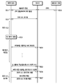
- the M2M device in the DCR mode when the M2M device in the DCR mode transmits UL data, a method of transmitting UL data while maintaining the DCR mode without ending the DCR mode will be described. That is, according to the present invention described below, the M2M device in the DCR mode may transmit UL data to the base station without performing network reentry to the base station.
- step S500 the network entity transmits an M2M CRID to the base station.
- the M2M device performs network entry to the base station.
- the M2M power saving class may be negotiated when the M2M device performs network entry, and the base station assigns the M2M CRID to the M2M device.
- step S502 DCR mode initialization is performed between the M2M device and the base station.
- step S503 the M2M device in the DCR mode generates UL data to transmit.
- the M2M device transmits an AAI-RNG-REQ message including the generated UL data to the base station.
- the UL data may be a short message service (SMS) message that does not exceed 140 bytes.
- SMS short message service
- Table 17 shows an example of an AAI-RNG-REQ message according to the proposed data transmission method.
- the Ranging Purpose indication field indicating the purpose of the AAI-RNG-REQ message includes a value indicating that the M2M device can transmit UL data in the DCR mode.
- an M2M CRID may be included in the AAI-RNG-REQ message to distinguish the M2M device in the DCR mode.
- step S505 the base station transmits an AAI-RNG-RSP message to the M2M device in response to the received AAI-RNG-REQ message.
- network reentry may be performed to terminate the DCR mode and transmit the UL data.
- step S510 the network entity transmits an M2M CRID to the base station.
- the M2M device performs network entry to the base station.
- the M2M power saving class may be negotiated when the M2M device performs network entry, and the base station assigns the M2M CRID to the M2M device.
- step S512 DCR mode initialization is performed between the M2M device and the base station.
- step S513 the M2M device in the DCR mode generates UL data to be transmitted.
- step S514 the M2M device transmits the AAI-RNG-REQ message including the generated UL data to the base station.
- the UL data may be an SMS message that does not exceed 140 bytes.
- AAI-RNG-REQ message may be defined as shown in Table 17.
- step S515 the base station transmits the AAI-RNG-RSP message to the M2M device in response to the received AAI-RNG-REQ message.
- the AAI-RNG-RSP message may indicate whether there is DL traffic to be transmitted by the base station.
- Table 18 shows an example of an AAI-RNG-RSP message according to the proposed data transmission method.
- DL traffic DL traffic for the firmware upgrade is an example of DL traffic to be sent to the M2M device in DCR mode.
- the base station has DL traffic to be sent to the M2M device ⁇ ... ⁇ - -
- the Location update response field in the AAI-RNG-RSP message may indicate a location update for short message transmission in DCR mode.
- the AAI-RNG-RSP message may include a Traffic Indication field indicating whether there is DL traffic to be transmitted to the M2M CRID and the M2M device.
- the Traffic Indication field may indicate whether there is DL traffic to be transmitted by the base station.
- step S5166 the M2M device terminates the DCR mode and performs network reentry with the base station. If there is DL traffic to be transmitted by the base station in step S517, the M2M device receives the DL traffic from the base station.
- the AAI-RNG-RSP message may indicate whether there is DL traffic to be transmitted by the base station, but may also indicate whether there is DL traffic to be transmitted by the base station through the aforementioned MTIEH or TIEH.
- the network entity transmits an M2M CRID to the base station.
- the M2M device performs network entry to the base station.
- the M2M power saving class may be negotiated when the M2M device performs network entry, and the base station assigns the M2M CRID to the M2M device.
- DCR mode initialization is performed between the M2M device and the base station.
- the M2M device in the DCR mode generates UL data to transmit.
- step S524 the M2M device transmits an AAI-RNG-REQ message including the generated UL data to the base station.
- the UL data may be an SMS message that does not exceed 140 bytes.
- AAI-RNG-REQ message may be defined as shown in Table 17.
- step S525 the base station transmits the AAI-RNG-RSP message to the M2M device in response to the received AAI-RNG-REQ message.
- the AAI-RNG-RSP message may indicate whether there is DL traffic to be transmitted by the base station.
- Table 19 shows an example of an AAI-RNG-RSP message according to the proposed data transmission method. Table 19 is a variation of Table 18.
- DL traffic DL traffic for the firmware upgrade is an example of DL traffic to be sent to the M2M device in DCR mode.
- the AAI-RNG-RSP message includes a DL Traffic Start Time field.
- the M2M device may know when DL traffic is received.
- the M2M device receives the DL traffic from the base station while maintaining the DCR mode.
- the M2M device receives the last DL traffic.
- the M2M device may receive DL traffic while maintaining the DCR mode, and monitor the DL only from the time indicated by the DL Traffic Start Time field in the AAI-RNG-RSP message to the last DL traffic to reduce power consumption.
- the last DL traffic may include the aforementioned MTEEH or TEEH. Accordingly, the M2M device may know that the received DL traffic is the last DL traffic, thereby reducing the power consumption of the M2M device.
- 16 is a block diagram of a wireless communication system in which an embodiment of the present invention is implemented.
- the base station 800 includes a processor 810, a memory 820, and an RF unit 830.
- Processor 810 implements the proposed functions, processes, and / or methods. Layers of the air interface protocol may be implemented by the processor 810.
- the memory 820 is connected to the processor 810 and stores various information for driving the processor 810.
- the RF unit 830 is connected to the processor 810 to transmit and / or receive a radio signal.
- the M2M device 900 includes a processor 910, a memory 920, and an RF unit 930.
- Processor 910 implements the proposed functions, processes, and / or methods. Layers of the air interface protocol may be implemented by the processor 910.
- the memory 920 is connected to the processor 910 and stores various information for driving the processor 910.
- the RF unit 930 is connected to the processor 910 to transmit and / or receive a radio signal.
- Processors 810 and 910 may include application-specific integrated circuits (ASICs), other chipsets, logic circuits, and / or data processing devices.
- the memory 820, 920 may include read-only memory (ROM), random access memory (RAM), flash memory, memory card, storage medium, and / or other storage device.
- the RF unit 830 and 930 may include a baseband circuit for processing a radio signal.
- the above-described technique may be implemented as a module (process, function, etc.) for performing the above-described function.
- the module may be stored in the memory 820, 920 and executed by the processor 810, 910.
- the memories 820 and 920 may be inside or outside the processors 810 and 910, and may be connected to the processors 810 and 910 by various well-known means.
Landscapes
- Engineering & Computer Science (AREA)
- Computer Networks & Wireless Communication (AREA)
- Signal Processing (AREA)
- Mobile Radio Communication Systems (AREA)
Abstract
무선 통신 시스템에서 데이터 전송 방법 및 장치가 제공된다. DCR(deregistration with context retention) 모드에 있는 M2M(machine-to-machine) 장치는 크기가 140바이트(byte)보다 작은 상향링크(UL; uplink) 데이터를 생성하고, 기지국으로 상기 UL 데이터를 포함하는 레인징 요청 메시지(AAI-RNG-REQ)를 전송하고, 상기 기지국으로부터 상기 레인징 요청 메시지에 대한 응답으로 레인징 응답 메시지(AAI-RNG-RSP)를 수신한다. 상기 레인징 요청 메시지는 상기 DCR 모드에서 상기 UL 데이터의 전송을 위한 위치 업데이트(location update)를 지시하는 레인징 목적 지시(ranging purpose indication) 필드를 포함한다. 또한, 상기 레인징 응답 메시지는 상기 레인징 목적 지시 필드에 대한 응답으로 상기 UL 데이터의 전송을 위한 위치 업데이트의 성공을 지시하는 위치 업데이트 응답(location update response) 필드를 포함한다.
Description
본 발명은 무선 통신에 관한 것으로, 보다 상세하게는 무선 통신 시스템에서 전력 절감 모드 내에서 데이터 전송 방법 및 장치에 관한 것이다.
IEEE(institute of electrical and electronics engineers) 802.16e 규격은 2007년 ITU(international telecommunication union) 산하의 ITU-R(ITU-radiocommunication sector)에서 IMT(international mobile telecommunication)-2000을 위한 여섯 번째 규격으로 'WMAN-OFDMA TDD'라는 이름으로 채택된 바 있다. ITU-R은 IMT-2000 이후의 차세대 4G 이동통신 규격으로 IMT-advanced 시스템을 준비하고 있다. IEEE 802.16 WG(working group)은 2006년 말 IMT-advanced 시스템을 위한 규격으로 기존 IEEE 802.16e의 수정(amendment) 규격을 작성하는 것을 목표로 IEEE 802.16m 프로젝트의 추진을 결정하였다. 상기 목표에서 알 수 있듯이, IEEE 802.16m 규격은 IEEE 802.16e 규격의 수정이라는 과거의 연속성과 차세대 IMT-advanced 시스템을 위한 규격이라는 미래의 연속성인 두 가지 측면을 내포하고 있다. 따라서, IEEE 802.16m 규격은 IEEE 802.16e 규격에 기반한 mobile WiMAX 시스템과의 호환성(compatibility)을 유지하면서 IMT-advanced 시스템을 위한 진보된 요구 사항을 모두 만족시킬 것을 요구하고 있다.
IEEE 802.16e 규격 및 IEEE 802.16m 규격을 기반으로 하며 기계 대 기계(M2M; machine-to-machine) 통신을 위하여 최적화된 IEEE 802.16p 규격이 개발 중에 있다. M2M 통신은 사람과의 어떤 상호 작용(interaction) 없이 핵심 망(core network) 내에서 가입자 국(subscriber station)과 서버(server) 간 또는 가입자국 간에 수행되는 정보 교환(information exchange)으로 정의될 수 있다. M2M 통신을 수행하는 장치를 M2M 장치라 할 수 있다. IEEE 802.16p 규격은 IEEE 802.16 규격의 MAC(medium access control)의 향상(enhancement)과 허가된 대역(licensed bands) 내에서 OFDMA(orthogonal frequency division multiple access) 물리 계층(PHY; physical layer)의 최소한의 변화를 논의 중에 있다. IEEE 802.16p 규격이 논의됨에 따라, 허가된 대역 내에서 광대역 무선 커버리지(wide area wireless coverage)를 요구하며 감시 및 제어(observation and control)의 목적을 위하여 자동화된(automated) M2M 통신의 적용 범위가 넓어질 수 있다.
수많은 M2M 어플리케이션(application)은 네트워크 접속(network access) 접속 시에, 일반적으로 사람에 의하여 개시되거나 제어되는(human-initiated or human-controlled) 네트워크 접속을 위한 요구 사항(requirements)과 상당히 다른 요구 사항을 요구한다. M2M 어플리케이션은 차량을 위한 통신(vehicular telematics), 생체 센서(bio-sensors)의 헬스 케어 모니터링(healthcare monitoring, 원격 유지 및 제어(remote maintenance and control), 스마트 계량기(smart metering) 및 소비자 장치(consumer device)의 자동화된 서비스(automated service) 등을 포함할 수 있다. M2M 어플리케이션의 요구 사항은 초저전력 소모(very lower power consumption), 많은 수의 장치 단말(larger numbers of devices), 짧은 버스트 전송(short burst transmission), 장치의 변경 검출 및 보고(device tampering detection and reporting) 향상된 장치 인증(improved device authentication) 등을 포함할 수 있다.
M2M 장치의 특성에 따라 M2M 장치의 동작을 최적화(optimize)할 수 있다. 예를 들어 M2M 장치의 이동성(mobility), 통신 타입(communication type), 스케줄링 지연(scheduling type)에 따라 각 M2M 장치가 진입할 전력 절감 모드(power saving mode)가 결정될 수 있다. 전력 절감 모드에 있을 때에도 기지국 또는 M2M 장치가 전송할 데이터가 존재할 수 있다. 전송할 데이터가 있을 때마다 전력 절감 모드에서 빠져 나와 네트워크 재진입(network reentry)을 수행하는 것은 비효율적일 수 있다.
따라서, 전력 절감 모드 내에서 효율적으로 데이터를 전송하기 위한 방법이 요구된다.
본 발명의 기술적 과제는 무선 통신 시스템에서 전력 절감 모드 내에서 데이터 전송 방법 및 장치를 제공하는 데에 있다. 본 발명은 DCR(deregistration with context retention) 모드에 있는 M2M 장치가 상향링크 데이터를 전송할 때, DCR 모드를 유지하면서 상향링크 데이터를 전송하는 방법을 제공한다.
일 양태에 있어서, 무선 통신 시스템에서 DCR(deregistration with context retention) 모드에 있는 M2M(machine-to-machine) 장치에 의한 데이터 전송 방법이 제공된다. 상기 데이터 전송 방법은 크기가 140바이트(byte)보다 작은 상향링크(UL; uplink) 데이터를 생성하고, 기지국으로 상기 UL 데이터를 포함하는 레인징 요청 메시지(AAI-RNG-REQ)를 전송하고, 상기 기지국으로부터 상기 레인징 요청 메시지에 대한 응답으로 레인징 응답 메시지(AAI-RNG-RSP)를 수신하는 것을 포함하되, 상기 레인징 요청 메시지는 상기 DCR 모드에서 상기 UL 데이터의 전송을 위한 위치 업데이트(location update)를 지시하는 레인징 목적 지시(ranging purpose indication) 필드를 포함하고, 상기 레인징 응답 메시지는 상기 레인징 목적 지시 필드에 대한 응답으로 상기 UL 데이터의 전송을 위한 위치 업데이트의 성공을 지시하는 위치 업데이트 응답(location update response) 필드를 포함한다.
상기 레인징 요청 메시지는 상기 DCR 모드에서 상기 M2M 장치에 할당되며 현재 유지되고 있는 M2M 장치 식별자인 컨텍스트 유지 식별자(CRID; context retention identifier)를 더 포함할 수 있다.
상기 레인징 응답 메시지는 상기 DCR 모드에서 상기 기지국이 상기 M2M 장치로 전송할 하향링크(DL; downlink) 데이터의 존재 여부를 지시하는 트래픽 지시(traffic indication) 필드를 더 포함할 수 있다.
상기 데이터 전송 방법은 상기 기지국으로 네트워크 재진입(network reentry)을 수행하여 상기 DCR 모드를 종료하고, 상기 기지국으로부터 상기 DL 데이터를 수신하는 것을 더 포함할 수 있다.
상기 트래픽 지시 필드의 값은 1이며, 상기 트래픽 지시 필드는 상기 기지국이 상기 M2M 장치로 전송할 DL 데이터가 있음을 지시할 수 있다.
상기 레인징 응답 메시지는 상기 기지국이 상기 DL 데이터를 전송하기 시작하는 프레임 번호(frame number)의 LSB(least significant bit) 8비트를 지시하는 DL 트래픽 시작 시간(DL traffic start time) 필드를 더 포함할 수 있다.
상기 데이터 전송 방법은 상기 DCR 모드를 종료하지 않은 상태에서 상기 기지국으로부터 상기 DL 데이터를 수신하는 것을 더 포함할 수 있다.
상기 기지국이 전송하는 상기 DL 데이터 중 마지막 DL 데이터는 멀티캐스트 트래픽 종료 확장 헤더(MTEEH; multicast traffic end extended header) 또는 트래픽 종료 확장 헤더(TEEH; traffic end extended header)를 포함할 수 있다.
상기 DCR 모드는 네트워크 진입(network entry) 시에 상기 기지국과 협상된 M2M 전력 절감 클래스(power saving class)를 기반으로 결정될 수 있다.
상기 데이터 전송 방법은 상기 네트워크 진입 시에 상기 기지국으로부터 상기 M2M 장치의 CRID를 수신하는 것을 더 포함할 수 있다.
다른 양태에 있어서, 무선 통신 시스템에서 DCR(deregistration with context retention) 모드에 있는 M2M(machine-to-machine) 장치가 제공된다. 상기 M2M 장치는 무선 신호를 전송 또는 수신하는 RF(radio frequency)부, 및 상기 RF부와 연결되는 프로세서를 포함하되, 상기 프로세서는 크기가 140바이트(byte)보다 작은 상향링크(UL; uplink) 데이터를 생성하고, 기지국으로 상기 UL 데이터를 포함하는 레인징 요청 메시지(AAI-RNG-REQ)를 전송하고, 상기 기지국으로부터 상기 레인징 요청 메시지에 대한 응답으로 레인징 응답 메시지(AAI-RNG-RSP)를 수신하도록 구성되며, 상기 레인징 요청 메시지는 상기 DCR 모드에서 상기 UL 데이터의 전송을 위한 위치 업데이트(location update)를 지시하는 레인징 목적 지시(ranging purpose indication) 필드를 포함하고, 상기 레인징 응답 메시지는 상기 레인징 목적 지시 필드에 대한 응답으로 상기 UL 데이터의 전송을 위한 위치 업데이트의 성공을 지시하는 위치 업데이트 응답(location update response) 필드를 포함한다.
DCR 모드에서 네트워크 재진입을 수행하지 않고 UL 데이터를 기지국으로 효율적으로 전송할 수 있다.
도 1은 무선 통신 시스템을 나타낸다.
도 2는 M2M(machine-to-machine) 통신을 지원하는 IEEE 802.16의 기본 M2M 서비스 시스템 구조를 나타낸다.
도 3은 M2M 통신을 지원하는 IEEE 802.16의 향상된(advanced) M2M 서비스 시스템 구조를 나타낸다.
도 4는 IEEE 802.16m의 프레임 구조의 일 예를 나타낸다.
도 5는 DCR 모드에 진입하는 M2M 장치의 동작의 일 예를 나타낸다.
도 6은 제안된 멀티캐스트 트래픽 수신 방법의 일 실시예를 나타낸다.
도 7은 제안된 멀티캐스트 트래픽 수신 방법의 또 다른 실시예를 나타낸다.
도 8은 제안된 멀티캐스트 트래픽 수신 방법의 또 다른 실시예를 나타낸다.
도 9는 제안된 멀티캐스트 트래픽 수신 방법의 또 다른 실시예를 나타낸다.
도 10은 제안된 멀티캐스트 트래픽 수신 방법의 또 다른 실시예를 나타낸다.
도 11은 제안된 멀티캐스트 트래픽 수신 방법의 또 다른 실시예를 나타낸다.
도 12는 아이들 모드에 진입하는 M2M 장치의 동작의 일 예를 나타낸다.
도 13은 제안된 데이터 전송 방법의 일 실시예를 나타낸다.
도 14는 제안된 데이터 전송 방법의 또 다른 실시예를 나타낸다.
도 15는 제안된 데이터 전송 방법의 또 다른 실시예를 나타낸다.
도 16은 본 발명의 실시예가 구현되는 무선 통신 시스템의 블록도이다.
이하의 기술은 CDMA(code division multiple access), FDMA(frequency division multiple access), TDMA(time division multiple access), OFDMA(orthogonal frequency division multiple access), SC-FDMA(single carrier frequency division multiple access) 등과 같은 다양한 무선 통신 시스템에 사용될 수 있다. CDMA는 UTRA(universal terrestrial radio access)나 CDMA2000과 같은 무선 기술(radio technology)로 구현될 수 있다. TDMA는 GSM(global system for mobile communications)/GPRS(general packet radio service)/EDGE(enhanced data rates for GSM evolution)와 같은 무선 기술로 구현될 수 있다. OFDMA는 IEEE 802.11(Wi-Fi), IEEE 802.16(WiMAX), IEEE 802-20, E-UTRA(evolved UTRA) 등과 같은 무선 기술로 구현될 수 있다. IEEE 802.16m은 IEEE 802.16e의 진화로, IEEE 802.16e에 기반한 시스템과의 하위 호환성(backward compatibility)를 제공한다. UTRA는 UMTS(universal mobile telecommunications system)의 일부이다. 3GPP(3rd generation partnership project) LTE(long term evolution)은 E-UTRA(evolved-UMTS terrestrial radio access)를 사용하는 E-UMTS(evolved UMTS)의 일부로써, 하향링크에서 OFDMA를 채용하고 상향링크에서 SC-FDMA를 채용한다. LTE-A(advanced)는 3GPP LTE의 진화이다.
설명을 명확하게 하기 위해, IEEE 802.16m을 위주로 기술하지만 본 발명의 기술적 사상이 이에 제한되는 것은 아니다.
도 1은 무선 통신 시스템을 나타낸다.
무선 통신 시스템(10)은 적어도 하나의 기지국(11; base station, BS)을 포함한다. 각 기지국(11)은 특정한 지리적 영역(일반적으로 셀이라고 함)(15a, 15b, 15c)에 대해 통신 서비스를 제공한다. 셀은 다시 다수의 영역(섹터라고 함)으로 나누어질 수 있다. 단말(12; user equipment, UE은 고정되거나 이동성을 가질 수 있으며, MS(mobile station), MT(mobile terminal), UT(user terminal), SS(subscriber station), 무선기기(wireless device), PDA(personal digital assistant), 무선 모뎀(wireless modem), 휴대기기(handheld device) 등 다른 용어로 불릴 수 있다. 기지국(11)은 일반적으로 단말(12)과 통신하는 고정된 지점(fixed station)을 말하며, eNB(evolved-NodeB), BTS(base transceiver system), 액세스 포인트(access point) 등 다른 용어로 불릴 수 있다.
단말은 하나의 셀에 속하는데, 단말이 속한 셀을 서빙 셀(serving cell)이라 한다. 서빙 셀에 대해 통신 서비스를 제공하는 기지국을 서빙 기지국(serving BS)이라 한다. 무선통신 시스템은 셀룰러 시스템(cellular system)이므로, 서빙 셀에 인접하는 다른 셀이 존재한다. 서빙 셀에 인접하는 다른 셀을 인접 셀(neighbor cell)이라 한다. 인접 셀에 대해 통신 서비스를 제공하는 기지국을 인접 기지국(neighbor BS)이라 한다. 서빙 셀 및 인접 셀은 단말을 기준으로 상대적으로 결정된다.
이 기술은 하향링크(downlink) 또는 상향링크(uplink)에 사용될 수 있다. 일반적으로 하향링크는 기지국(11)에서 단말(12)로의 통신을 의미하며, 상향링크는 단말(12)에서 기지국(11)으로의 통신을 의미한다. 하향링크에서 송신기는 기지국(11)의 일부분이고, 수신기는 단말(12)의 일부분일 수 있다. 상향링크에서 송신기는 단말(12)의 일부분이고, 수신기는 기지국(11)의 일부분일 수 있다.
도 2는 M2M(machine-to-machine) 통신을 지원하는 IEEE 802.16의 기본 M2M 서비스 시스템 구조를 나타낸다.
기본 M2M 서비스 시스템 구조(20)는 이동 네트워크 오퍼레이터(MNO; mobile network operator, 21), M2M 서비스 소비자(service consumer, 24), 적어도 하나의 IEEE 802.16 M2M 장치(이하, 802.16 M2M 장치, 28), 적어도 하나의 비 IEEE 802.16 M2M 장치(29)를 포함한다. MNO(21)는 접속 서비스 네트워크(ASN; access service network)와 연결 서비스 네트워크(CSN; connectivity service network)를 포함한다. 802.16 M2M 장치(28)는 M2M 기능(functionality)을 가진 IEEE 802.16 단말이다. M2M 서버(23)는 하나 이상의 802.16 M2M 장치(28)와 통신하는 개체(entity)이다. M2M 서버(23)는 M2M 서비스 소비자(24)가 접속할 수 있는 인터페이스(interface)를 가진다. M2M 서비스 소비자(24)는 M2M 서비스의 사용자이다. M2M 서버(23)는 연결 서비스 네트워크(CSN; connectivity service network) 내부 또는 외부에 있을 수 있으며, 하나 이상의 802.16 M2M 장치(28)에 특정 M2M 서비스를 제공할 수 있다. ASN은 IEEE 802.16 기지국(22)를 포함할 수 있다. M2M 어플리케이션(application)은 802.16 M2M 장치(28) 및 M2M 서버(23)를 기반으로 운영된다.
기본 M2M 서비스 시스템 구조(20)는 하나 이상의 802.16 M2M 장치들과 M2M 서버 간의 M2M 통신 또는 802.16 M2M 장치들과 IEEE 802.16 기지국 간의 점대다(point-to-multipoint) 통신의 2가지 종류의 M2M 통신을 지원한다. 도 2의 기본 M2M 서비스 시스템 구조는 802.16 M2M 장치가 비 IEEE 802.16 M2M 장치를 위한 집합점(aggregation point)으로 동작하는 것을 허용한다. 비 IEEE 802.16 M2M 장치는 IEEE 802.11, IEEE 802.15 또는 PLC 등의 IEEE 802.16과 다른 무선 인터페이스를 사용한다. 이때 비 IEEE 802.16 M2M 장치의 IEEE 802.16으로의 무선 인터페이스의 변경은 허용되지 않는다.
도 3은 M2M 통신을 지원하는 IEEE 802.16의 향상된(advanced) M2M 서비스 시스템 구조를 나타낸다.
향상된 M2M 서비스 시스템 구조에서도 마찬가지로 802.16 M2M 장치가 비 IEEE 802.16 M2M 장치를 위한 집합점으로 동작할 수 있으며, 또한, 802.16 M2M 장치를 위한 집합점으로 동작할 수도 있다. 이때 802.16 M2M 장치 및 비 802.16 M2M 장치를 위한 집합 기능을 수행하기 위하여, 무선 인터페이스가 IEEE 802.16으로 변경될 수 있다. 또한 향상된 M2M 서비스 시스템 구조에서 802.16 M2M 장치들 간의 P2P(peer-to-peer) 연결이 지원될 수 있으며, 이때 P2P 연결은 IEEE 802.16 상으로 또는 IEEE 802.11, IEEE 802.15 또는 PLC 등의 다른 무선 인터페이스 상으로 연결될 수 있다.
도 4는 IEEE 802.16m의 프레임 구조의 일 예를 나타낸다.
도 4를 참조하면, 슈퍼프레임(SF; superframe)은 슈퍼프레임 헤더(SFH; superframe header)와 4개의 프레임(frame, F0, F1, F2, F3)을 포함한다. 슈퍼프레임 내 각 프레임의 길이는 모두 동일할 수 있다. 각 슈퍼프레임의 크기는 20ms이고, 각 프레임의 크기는 5ms인 것으로 예시하고 있으나, 이에 한정되는 것은 아니다. 슈퍼프레임의 길이, 슈퍼프레임에 포함되는 프레임의 수, 프레임에 포함되는 서브프레임의 수 등은 다양하게 변경될 수 있다. 프레임에 포함되는 서브프레임의 수는 채널 대역폭(channel bandwidth), CP(cyclic prefix)의 길이에 따라 다양하게 변경될 수 있다.
하나의 프레임은 다수의 서브프레임(subframe, SF0, SF1, SF2, SF3, SF4, SF5, SF6, SF7)을 포함한다. 각 서브프레임은 상향링크 또는 하향링크 전송을 위하여 사용될 수 있다. 하나의 서브프레임은 시간 영역(time domain)에서 복수의 OFDM(orthogonal frequency division multiplexing) 심벌 또는 OFDMA(orthogonal frequency division multiple access)을 포함하고, 주파수 영역(frequency domain)에서 복수의 부반송파(subcarrier)를 포함한다. OFDM 심벌은 하나의 심벌 구간(symbol period)을 표현하기 위한 것으로, 다중 접속 방식에 따라 OFDMA 심벌, SC-FDMA 심벌 등 다른 명칭으로 불릴 수 있다. 서브프레임은 5, 6, 7 또는 9개의 OFDMA 심벌로 구성될 수 있으나, 이는 예시에 불과하며 서브프레임에 포함되는 OFDMA 심벌의 수는 제한되지 않는다. 서브프레임에 포함되는 OFDMA 심벌의 수는 채널 대역폭, CP의 길이에 따라 다양하게 변경될 수 있다. 서브프레임이 포함하는 OFDMA 심벌의 수에 따라 서브프레임의 타입(type)이 정의될 수 있다. 예를 들어, 타입-1 서브프레임은 6 OFDMA 심벌, 타입-2 서브프레임은 7 OFDMA 심벌, 타입-3 서브프레임은 5 OFDMA 심벌, 타입-4 서브프레임은 9 OFDMA 심벌을 포함하는 것으로 정의될 수 있다. 하나의 프레임은 모두 동일한 타입의 서브프레임을 포함할 수 있다. 또는 하나의 프레임은 서로 다른 타입의 서브프레임을 포함할 수 있다. 즉, 하나의 프레임 내 각 서브프레임마다 포함하는 OFDMA 심벌의 개수는 모두 동일하거나, 각각 다를 수 있다. 또는, 하나의 프레임 내 적어도 하나의 서브프레임의 OFDMA 심벌의 개수는 상기 프레임 내 나머지 서브프레임의 OFDMA 심벌의 개수와 다를 수 있다.
프레임에는 TDD 방식 또는 FDD(frequency division duplex) 방식이 적용될 수 있다. TDD 방식에서 각 서브프레임이 동일한 주파수에서 서로 다른 시간에 상향링크 전송 또는 하향링크 전송을 위해 사용된다. 즉, TDD 방식의 프레임 내의 서브프레임들은 시간 영역에서 상향링크 서브프레임과 하향링크 서브프레임으로 구분된다. FDD 방식에서 각 서브프레임이 동일한 시간의 서로 다른 주파수에서 상향링크 전송 또는 하향링크 전송을 위해 사용된다. 즉, FDD 방식의 프레임 내의 서브프레임들은 주파수 영역에서 상향링크 서브프레임과 하향링크 서브프레임으로 구분된다. 상향링크 전송과 하향링크 전송은 서로 다른 주파수 대역을 차지하고, 동시에 이루어질 수 있다.
SFH는 필수 시스템 파라미터(essential system parameter) 및 시스템 설정 정보(system configuration information)를 나를 수 있다. SFH는 슈퍼프레임 내 첫 번째 서브프레임 안에 위치할 수 있다. SFH는 상기 첫 번째 서브프레임의 마지막 5개의 OFDMA 심벌을 차지할 수 있다. 슈퍼프레임 헤더는 1차 SFH(P-SFH; primary-SFH) 및 2차 SFH(S-SFH; secondary-SFH)로 분류될 수 있다. P-SFH는 매 슈퍼프레임마다 전송될 수 있다. S-SFH로 전송되는 정보는 S-SFH SP1, S-SFH SP2, S-SFH SP3의 3개의 서브패킷(sub-packet)으로 나뉠 수 있다. 각 서브패킷은 서로 다른 주기를 가지고 주기적으로 전송될 수 있다. S-SFH SP1, S-SFH SP2 및 S-SFH SP3을 통해 전송되는 정보의 중요도는 서로 다를 수 있으며, S-SFH SP1이 가장 짧은 주기로, S-SFH SP3이 가장 긴 주기로 전송될 수 있다. S-SFH SP1은 네트워크 재진입(network re-entry)에 관한 정보를 포함하며, S-SFH SP1의 전송 주기는 40 ms일 수 있다. S-SFH SP2는 초기 네트워크 진입(initial network entry) 및 네트워크 탐색(network discovery)에 관한 정보를 포함하며, S-SFH SP2의 전송 주기는 80 ms일 수 있다. S-SFH SP3는 나머지 중요한 시스템 정보를 포함하며, S-SFH SP3의 전송 주기는 160 ms 또는 320 ms 중 어느 하나일 수 있다.
하나의 OFDMA 심벌은 복수의 부반송파를 포함하고, FFT 크기에 따라 부반송파의 개수가 결정된다. 몇 가지 유형의 부반송파가 있다. 부반송파의 유형은 데이터 전송을 위한 데이터 부반송파, 다양한 측정(estimation)을 위한 파일롯 부반송파, 가드 밴드(guard band) 및 DC 캐리어를 위한 널 캐리어로 나뉠 수 있다. OFDMA 심벌을 특징짓는 파라미터는 BW, Nused, n, G 등이다. BW는 명목상의 채널 대역폭(nominal channel bandwidth)이다. Nused는 (DC 부반송파를 포함하는) 사용되는 부반송파의 개수이다. n은 샘플링 인자이다. 이 파라미터는 BW 및 Nused와 결합하여 부반송파 스페이싱(spacing) 및 유효 심벌 시간(useful symbol time)을 결정한다. G는 CP 시간과 유효 시간(useful time)의 비율이다.
아래 표 1은 OFDMA 파라미터를 나타낸다. 표 1의 OFDMA 파라미터는 도 4의 802.16e의 프레임 구조에도 동일하게 사용될 수 있다.
| Channel bandwidth, BW(MHz) | 5 | 7 | 8.75 | 10 | 20 | ||
| Sampling factor, n | 28/25 | 8/7 | 8/7 | 28/25 | 28/25 | ||
| Sampling frequency, Fs(MHz) | 5.6 | 8 | 10 | 11.2 | 22.4 | ||
| FFT size, NFFT | 512 | 1024 | 1024 | 1024 | 2048 | ||
| Subcarrier spacing, Δf(kHz) | 10.94 | 7.81 | 9.77 | 10.94 | 10.94 | ||
| Useful symbol time, Tb(μs) | 91.4 | 128 | 102.4 | 91.4 | 91.4 | ||
| G=1/8 | Symbol time, Ts(μs) | 102.857 | 144 | 115.2 | 102.857 | 102.857 | |
| FDD | Number of ODFMA symbols per 5ms frame |
48 | 34 | 43 | 48 | 48 | |
| Idle time(μs) | 62.857 | 104 | 46.40 | 62.857 | 62.857 | ||
| TDD | Number of ODFMA symbols per 5ms frame |
47 | 33 | 42 | 47 | 47 | |
| TTG+RTG(μs) | 165.714 | 248 | 161.6 | 165.714 | 165.714 | ||
| G=1/16 | Symbol time, Ts(μs) | 97.143 | 136 | 108.8 | 97.143 | 97.143 | |
| FDD | Number of ODFMA symbols per 5ms frame |
51 | 36 | 45 | 51 | 51 | |
| Idle time(μs) | 45.71 | 104 | 104 | 45.71 | 45.71 | ||
| TDD | Number of ODFMA symbols per 5ms frame |
50 | 35 | 44 | 50 | 50 | |
| TTG+RTG(μs) | 142.853 | 240 | 212.8 | 142.853 | 142.853 | ||
| G=1/4 | Symbol time, Ts(μs) | 114.286 | 160 | 128 | 114.286 | 114.286 | |
| FDD | Number of ODFMA symbols per 5ms frame |
43 | 31 | 39 | 43 | 43 | |
| Idle time(μs) | 85.694 | 40 | 8 | 85.694 | 85.694 | ||
| TDD | Number of ODFMA symbols per 5ms frame |
42 | 30 | 38 | 42 | 42 | |
| TTG+RTG(μs) | 199.98 | 200 | 136 | 199.98 | 199.98 | ||
| Number of Guard subcarriers | Left | 40 | 80 | 80 | 80 | 160 | |
| Right | 39 | 79 | 79 | 79 | 159 | ||
| Number of used subcarriers | 433 | 865 | 865 | 865 | 1729 | ||
| Number of PRU in type-1 subframe | 24 | 48 | 48 | 48 | 96 | ||
표 1에서, NFFT는 Nused보다 큰 수 중에서 가장 작은 2n 가운데 가장 작은 파워(Smallest power of two greater than Nused)이고, 샘플링 인자 Fs=floor(n·BW/8000)×8000이며, 부반송파 스페이싱 Δf=Fs/NFFT이고, 유효 심벌 시간 Tb=1/Δf이며, CP 시간 Tg=G·Tb이고, OFDMA 심벌 시간 Ts=Tb+Tg이며, 샘플링 시간은 Tb/NFFT이다.
M2M 장치의 특성에 따라 M2M 장치의 동작을 최적화(optimize)할 수 있다. 특히 M2M 장치의 특성에 따라 M2M 장치의 전력 절감(power saving)과 관련된 특성이 정의될 수 있다. 예를 들어 M2M 장치의 이동성(mobility), 통신 타입(communication type), 스케줄링 지연(scheduling type)에 따라 각 M2M 장치가 진입할 전력 절감 모드가 결정될 수 있다. M2M 장치가 진입할 수 있는 전력 절감 모드는 아이들 모드(idle mode) 또는 DCR(deregistration with context retention) 모드 중 어느 하나일 수 있다. DCR 모드는 단말이 네트워크로부터 등록 해제(deregistered)되지만, 컨텍스트 유지 타이머가 만료되기 전에는 단말의 컨텍스트가 네트워크에 보관되는 모드를 나타낸다. 컨텍스트 유지 타이머가 유효(valid)한 동안, 네트워크는 단말의 네트워크 재진입(network reentry)을 신속하게 처리할 수 있도록 단말의 정보를 보유한다. 또한, 각 단말에 할당된 CRID(context retention identifier)가 DCR 모드에 있는 단말을 식별하기 위하여 사용될 수 있다.
표 2는 M2M 장치의 이동성, 통신 타입 및 스케줄링 지연에 따라 결정되는 M2M 장치의 전력 절감 클래스 및 전력 절감 모드의 일 예를 나타낸다.
| M2M 전력 절감 클래스 특성(power saving class properties | 이동성 (mobility) |
통신 타입(communication type) | 스케줄링 지연(scheduling delay) | 전력 절감 모드(power saving mode) |
| M2M PSC1 | No | 장치 유발(device originated only) | 참을 수 있음(tolerant) | DCR 모드 |
| M2M PSC2 | No | 네트워크 유발(network originated only) | tolerant | 아이들 모드 |
| M2M PSC3 | No | 모두 유발(both originated) | 참을 수 없음(intolerant) | 아이들 모드 |
| M2M PSC4 | Yes | network originated only | intolerant | 아이들 모드 |
| M2M PSC5 | Yes | network originated only | tolerant | 아이들 모드 |
| M2M PSC6 | Yes | both originated | intolerant | 아이들 모드 |
| ... | ... | ... | ... | ... |
| M2M PSCN | Yes | device originated only | tolerant | DCR 모드 |
표 2를 참조하면, M2M 장치의 전력 절감 모드를 결정하기 위하여 이동성, 통신 타입 및 스케줄링 지연의 특성이 사용될 수 있다. 이동성은 M2M 장치가 고정되는지 이동하는지 여부를 지시한다. 통신 타입은 M2M 통신으로 전송되는 데이터의 방향을 지시한다. 즉, 통신 타입이 ‘device originated only’인 경우, M2M 장치가 기지국으로 전송하는 트래픽만이 존재하고, 통신 타입이 ‘network originated only’인 경우, 기지국이 M2M 장치로 전송하는 트래픽만이 존재한다. 스케줄링 지연은 전송되는 트래픽이 지연에 민감한지 여부를 지시한다.
표 2와 같이 정의된 M2M 전력 절감 클래스는 M2M 장치와 기지국 또는 다른 네트워크 개체 간에 미리 결정될 될 수 있고, 또는 네트워크 진입 단계에서 M2M 장치와 기지국이 서로 협상하여 결정될 수 있다. 이와 같이 결정된 M2M 전력 절감 클래스를 기반으로 M2M 장치의 전력 절감 모드가 결정될 수 있다.
표 3은 표 2에 의하여 정의된 M2M 전력 절감 클래스를 기반으로 각 M2M 장치에 필요한 기능과 필요하지 않은 기능 및 각 M2M 장치의 전력 절감 모드를 나타낸 것이다.
| M2M 전력 절감 클래스 | 설 명 |
| M2M PSC 1 | 이동성이 없으며 M2M 장치가 전송할 데이터가 있을 때에만 기지국으로 데이터를 전송하므로, 페이징(paging) 및 위치 업데이트(location update) 절차가 필요하지 않다. 페이징: 지원되지 않음 타이머 기반 위치 업데이트: 지원되지 않음 페이징 그룹 기반 위치 업데이트: 지원되지 않음 페이징 그룹 ID, 페이징 컨트롤러 ID: 할당되지 않음 등록 해제(deregistration) ID(아이들 모드 식별자): 사용되지 않음 페이징 주기(paging cycle), 페이징 오프셋(paging offset), 페이징 수신 인터벌(paging listening interval) 없음 전력 절감 모드: DCR 모드 |
| M2M PSC 2 | 이동성이 없으므로 페이징 그룹 기반 위치 업데이트가 필요하지 않다. 오직 기지국이 M2M 장치로 데이터를 전송하므로, M2M 장치로의 DL 알림(notification) 매커니즘이 필요하다. 따라서 페이징이 지원되어야 한다. 페이징: 지원됨 타이머 기반 위치 업데이트: 지원됨 페이징 그룹 기반 위치 업데이트: 지원되지 않음 페이징 그룹 ID: 할당되지 않음, MGID(M2M group ID)로 페이징 페이징 컨트롤러 ID: 할당됨 등록 해제 ID: 사용됨(M2M DID(device ID)) 페이징 주기, 페이징 오프셋 할당 전력 절감 모드: 아이들 모드 |
| M2M PSC 3 | 이동성이 없으므로 페이징 그룹 기반 위치 업데이트가 필요하지 않다. 기지국이 M2M 장치로 데이터를 전송할 수 있으므로, M2M 장치로의 DL 알림 매커니즘이 필요하다. 따라서 페이징이 지원되어야 한다. 페이징: 지원됨 타이머 기반 위치 업데이트: 지원됨 페이징 그룹 기반 위치 업데이트: 지원되지 않음 페이징 그룹 ID: 할당되지 않음, MGID(M2M group ID)로 페이징 페이징 컨트롤러 ID: 할당됨 등록 해제 ID: 사용됨(M2M DID) 페이징 주기, 페이징 오프셋 할당 전력 절감 모드: 아이들 모드 |
| M2M PSC 4 | 이동성이 있으므로 위치 업데이트 절차가 필요하다. 기지국이 M2M 장치로 데이터를 전송할 수 있으므로, M2M 장치로의 DL 알림 매커니즘이 필요하다. 따라서 페이징이 지원되어야 한다. 페이징: 지원됨 타이머 기반 위치 업데이트: 지원됨 페이징 그룹 기반 위치 업데이트: 지원됨 페이징 그룹 ID, 페이징 컨트롤러 ID: 할당됨 등록 해제 ID: 사용됨(M2M DID) 페이징 주기, 페이징 오프셋 할당 전력 절감 모드: 아이들 모드 |
| … | … |
| M2M PSC N | 이동성이 없으며 M2M 장치가 전송할 데이터가 있을 때에만 기지국으로 데이터를 전송하므로, 페이징 및 위치 업데이트 절차가 필요하지 않다. 페이징: 지원되지 않음 타이머 기반 위치 업데이트: 지원되지 않음 페이징 그룹 기반 위치 업데이트: 지원되지 않음 페이징 그룹 ID, 페이징 컨트롤러 ID: 할당되지 않음 등록 해제 ID(아이들 모드 식별자): 사용되지 않음 페이징 주기, 페이징 오프셋, 페이징 수신 인터벌 없음 전력 절감 모드: DCR 모드 |
표 2 및 표 3에서 나타난 바와 같이, M2M 장치가 필요한 경우에 상향링크(UL; uplink) 데이터를 기지국으로 전송하고 해당 UL 데이터가 스케줄링 지연에 민감하지 않은 경우, 해당 M2M 장치의 전력 절감 모드로 DCR 모드가 사용될 수 있다.
도 5는 DCR 모드에 진입하는 M2M 장치의 동작의 일 예를 나타낸다.
단계 S100에서 네트워크 개체는 기지국으로 M2M 장치의 CRID(이하 M2M CRID)를 전송한다. 단계 S101에서 M2M 장치는 기지국으로 네트워크 진입을 수행한다. M2M 장치가 네트워크 진입을 수행할 때 M2M 전력 절감 클래스가 협의될 수 있고, 기지국은 M2M CRID를 M2M 장치에 할당한다.
단계 S102에서 M2M 장치와 기지국 사이에서 DCR 모드 초기화(initiation)가 수행된다. DCR 모드 초기화는 연결 모드(connected mode) 또는 아이들 모드에서 수행될 수 있다. DCR 모드 초기화가 연결 모드에서 수행되는 경우, M2M 장치는 등록 해제 요청 메시지(AAI-DREG-REQ)를 전송하여 DCR 모드를 초기화할 수 있다. M2M 장치는 AAI-DREG-REQ 메시지를 통해 DCR 모드를 위한 특정 서비스 및 동작 정보를 유지할 것을 기지국에 요청할 수 있다. 기지국이 M2M 장치의 요청을 받아들이는 경우, 기지국은 M2M 장치로 등록 해제 응답 메시지(AAI-DREG-RSP)를 전송할 수 있다. AAI-DREG-RSP 메시지를 수신한 M2M 장치는 컨텍스트 유지 타이머를 시작한다. DCR 모드 초기화가 아이들 모드에서 수행되는 경우, M2M 장치는 레인징 요청 메시지(AAI-RNG-REQ)를 통해 위치 업데이트를 수행하여 DCR 모드를 초기화할 수 있다. 기지국이 M2M 장치의 요청을 받아들이는 경우, 기지국은 M2M 장치로 레인징 응답 메시지(AAI-RNG-RSP)를 전송할 수 있다. AAI-RNG-RSP 메시지를 수신한 M2M 장치는 컨텍스트 유지 타이머를 시작한다. 컨텍스트 유지 타이머가 유효한 동안, 네트워크는 M2M 장치의 정보를 유지한다.
단계 S103에서 DCR 모드에 있는 M2M 장치는 전송할 UL 데이터를 생성한다. 단계 S104에서 M2M 장치와 기지국 사이에서 네트워크 재진입이 수행된다. 이때 M2M CRID를 통해 최적화된 네트워크 재진입이 수행될 수 있다. M2M 장치는 기지국으로 M2M CRID를 포함하는 AAI-RNG-REQ 메시지를 전송하여 네트워크 재진입을 초기화할 수 있다. 단계 S105에서 기지국은 M2M CRID를 이용하여 네트워크가 유지하던 M2M 장치의 정보를 회수한다.
DCR 모드는 M2M 장치가 네트워크로 재진입하거나, 컨텍스트 유지 타이머가 만료된 경우에 종료(terminate)될 수 있다.
DCR 모드에서 M2M 장치는 페이징 메시지를 수신하지 않으므로, 기지국 또는 네트워크 개체가 전송하는 멀티캐스트(multicast) 트래픽을 수신할 수 없다. 이는 페이징 메시지가 멀티캐스트 트래픽의 존재 유무를 지시하는 정보를 포함하기 때문이다. 멀티캐스트 트래픽은 기지국으로부터 복수의 M2M 장치에 동시에 전송되는 데이터로, 펌웨어 업그레이드(firmware upgrade) 관련 데이터 등을 포함할 수 있다.
네트워크 재진입에 따라 DCR 모드가 종료되는 경우, M2M 장치가 멀티캐스트 트래픽을 수신하기 위한 방법이 요구될 수 있다. 이를 위하여 멀티캐스트 트래픽 지시 확장 헤더(MTIEH; multicast traffic indication extended header)가 새롭게 정의될 수 있다.
표 4는 본 발명에 의하여 새롭게 정의되는 MTIEH의 일 예를 나타낸다.
| 필 드 | 크기(bit) | 설 명 |
| Multicast Transmission Indication Extended Header Format () { | ||
| Type | 4 | 확장 헤더 타입=0b1001 (MTIEH 타입) |
| Response Indication | 1 | 0: 요청을 지시함 1: 요청에 대한 응답(예를 들어, ACK)을 지시함 |
| if (Response Indication = =1) { | ||
| Multicast Transmission Indication | 1 | 멀티캐스트 트래픽의 존재를 지시함. 0: 멀티캐스트 트래픽 없음 1: 멀티캐스트 트래픽 있음 |
| } | ||
| if (Multicast Transmission Indication == 1) { | ||
| Multicast transmission start time (MTST) | 8 | 기지국이 DL 멀티캐스트 데이터를 전송하기 시작하는 프레임 번호의 LSB(least significant bit) 8비트 |
| } | ||
| Reserved | variable | 바이트 정렬(byte alignment) |
| } | - | - |
표 4를 참조하면, MTIEH는 Response Indication 필드를 포함하며, Response Indication 필드의 값이 1일 때 Multicast Transmission Indication 필드를 포함한다. Multicast Transmission Indication 필드는 기지국이 전송할 멀티캐스트 트래픽의 존재 여부를 지시한다.
표 4의 MTIEH는 멀티캐스트 트래픽의 존재 여부를 멀티캐스트 방식으로 지시하나, 이와 유사한 방법으로 DL 트래픽의 존재 여부를 유니캐스트(unicast) 방식으로 지시할 수 있다. DL 트래픽의 존재 여부를 유니캐스트 방식으로 지시하기 위하여 표 4와 유사한 트래픽 지시 확장 헤더(TIEH; traffic indication extended header)가 표 5와 같이 정의될 수 있다.
| 필 드 | 크기(bit) | 설 명 |
| Transmission Indication Extended Header Format () { | ||
| Type | 4 | 확장 헤더 타입=0b1001 (TIEH 타입) |
| Response Indication | 1 | 0: 요청을 지시함 1: 요청에 대한 응답(예를 들어, ACK)을 지시함 |
| if (Response Indication = =1) { | ||
| Traffic Indication | 1 | DL 트래픽의 존재를 지시함. 0: DL 트래픽 없음 1: DL 트래픽 있음 |
| } | ||
| if (Traffic Indication == 1) { | ||
| Traffic start time | 8 | 기지국이 DL 데이터를 전송하기 시작하는 프레임 번호의 LSB 8비트 |
| } | ||
| Reserved | variable | 바이트 정렬 |
| } | - | - |
표 5를 참조하면, TIEH는 Response Indication 필드를 포함하면, Response Indication 필드의 값이 1일 때 Traffic Indication 필드를 포함한다. Traffic Indication 필드는 기지국이 전송할 DL 트래픽의 존재 여부를 지시한다.
도 6은 제안된 멀티캐스트 트래픽 수신 방법의 일 실시예를 나타낸다.
M2M 장치는 네트워크 재진입을 통하여 DCR 모드를 종료하는 경우, MTIEH를 통해 기지국으로부터 멀티캐스트 트래픽을 수신할 수 있다. 수집한 정보를 네트워크에 전송만 하는 스마트 미터링(smart metering) 장치와 같은 M2M 장치는, 멀티캐스트 트래픽을 수신하기 위하여 주기적으로 DL을 모니터링하여 멀티캐스트 트래픽의 존재 여부를 확인하지 않고, DCR 모드가 종료되고 UL 데이터가 전송될 때 멀티캐스트 트래픽의 존재 여부를 확인할 수 있다.
도 6을 참조하면, 단계 S200에서 네트워크 개체는 기지국으로 M2M CRID를 전송한다. 단계 S201에서 M2M 장치는 기지국으로 네트워크 진입을 수행한다. M2M 장치가 네트워크 진입을 수행할 때 M2M 전력 절감 클래스가 협의될 수 있고, 기지국은 M2M CRID를 M2M 장치에 할당한다. 단계 S202에서 M2M 장치와 기지국 사이에서 DCR 모드 초기화가 수행된다. 단계 S203에서 DCR 모드에 있는 M2M 장치는 전송할 UL 데이터를 생성한다. 이에 따라 M2M 장치는 기지국으로의 네트워크 재진입을 수행한다.
단계 S204에서 M2M 장치는 기지국으로 표 4에서 정의된 MTIEH를 가진 MAC 메시지를 전송한다. 이때 MTIEH 내의 Response Indication 필드의 값은 0일 수 있다. 즉, Response Indication 필드는 요청을 지시할 수 있다. 단계 S205에서 기지국은 M2M 장치로 MTIEH를 가진 MAC 메시지를 전송한다. 이때 MTIEH 내의 Response Indication 필드의 값은 1일 수 있다. 즉, Response Indication 필드는 응답을 지시할 수 있다. 따라서 기지국은 MTIEH 내의 Multicast transmission Indication 필드를 통해 멀티캐스트 트래픽의 존재 여부를 M2M 장치에 지시할 수 있다.
단계 S206에서 M2M 장치는 기지국으로 생성된 UL 데이터를 전송하고, 멀티캐스트 트래픽이 존재하는 경우 기지국으로부터 멀티캐스트 트래픽을 수신한다.
도 7은 제안된 멀티캐스트 트래픽 수신 방법의 또 다른 실시예를 나타낸다.
도 7을 참조하면, 단계 S210에서 네트워크 개체는 기지국으로 M2M CRID를 전송한다. 단계 S211에서 M2M 장치는 기지국으로 네트워크 진입을 수행한다. M2M 장치가 네트워크 진입을 수행할 때 M2M 전력 절감 클래스가 협의될 수 있고, 기지국은 M2M CRID를 M2M 장치에 할당한다. 단계 S212에서 M2M 장치와 기지국 사이에서 DCR 모드 초기화가 수행된다. 단계 S213에서 DCR 모드에 있는 M2M 장치는 전송할 UL 데이터를 생성한다. 이에 따라 M2M 장치는 기지국으로의 네트워크 재진입을 수행한다.
단계 S214에서 기지국은 M2M 장치로 MTIEH를 가진 MAC 메시지를 전송한다. MTIEH는 표 6과 같이 정의될 수 있다. 표 6은 표 4의 변형이다.
| 필 드 | 크기(bit) | 설 명 |
| Multicast Transmission Indication Extended Header Format () { | ||
| Type | 4 | 확장 헤더 타입=0b1001 (MTIEH 타입) |
| Multicast Traffic Indication | 1 | 멀티캐스트 트래픽의 존재를 지시함 0: 멀티캐스트 트래픽 없음 1: 멀티캐스트 트래픽 있음 |
| if (Multicast Traffic Indication == 1) { | ||
| Multicast transmission start time (MTST) | 8 | 기지국이 DL 멀티캐스트 데이터를 전송하기 시작하는 프레임 번호의 LSB 8비트 |
| } | ||
| Reserved | variable | 바이트 정렬 |
| } | - | - |
표 6을 참조하면, 기지국은 MTIEH 내의 Multicast Traffic Indication 필드를 통해 멀티캐스트 트래픽의 존재 여부를 M2M 장치에 지시할 수 있다.
또는, DL 트래픽의 존재 여부를 유니캐스트 방식으로 지시하기 위하여 TIEH가 표 7과 같이 정의될 수 있다. 표 7은 표 5의 변형이다.
| 필 드 | 크기(bit) | 설 명 |
| Transmission Indication Extended Header Format () { | ||
| Type | 4 | 확장 헤더 타입=0b1001 (TIEH 타입) |
| Traffic Indication | 1 | DL 트래픽의 존재를 지시함. 0: DL 트래픽 없음 1: DL 트래픽 있음 |
| if (Traffic Indication == 1) { | ||
| Traffic start time | 8 | 기지국이 DL 데이터를 전송하기 시작하는 프레임 번호의 LSB 8비트 |
| } | ||
| Reserved | variable | 바이트 정렬 |
| } | - | - |
표 7을 참조하면, 기지국은 TIEH 내의 Traffic Indication 필드를 통해 DL 트래픽의 존재 여부를 M2M 장치에 지시할 수 있다.
다시 도 7을 참조하면, 단계 S215에서 M2M 장치는 기지국으로 생성된 UL 데이터를 전송하고, 멀티캐스트 트래픽이 존재하는 경우 기지국으로부터 멀티캐스트 트래픽을 수신한다.
도 8은 제안된 멀티캐스트 트래픽 수신 방법의 또 다른 실시예를 나타낸다.
도 8을 참조하면, 단계 S220에서 네트워크 개체는 기지국으로 M2M CRID를 전송한다. 단계 S221에서 M2M 장치는 기지국으로 네트워크 진입을 수행한다. M2M 장치가 네트워크 진입을 수행할 때 M2M 전력 절감 클래스가 협의될 수 있고, 기지국은 M2M CRID를 M2M 장치에 할당한다. 단계 S222에서 M2M 장치와 기지국 사이에서 DCR 모드 초기화가 수행된다. 단계 S223에서 DCR 모드에 있는 M2M 장치는 전송할 UL 데이터를 생성한다. 이에 따라 M2M 장치는 기지국으로의 네트워크 재진입을 수행한다.
단계 S224에서 M2M 장치는 기지국으로 레인징 요청 메시지(AAI-RNG-REQ)를 전송한다. 단계 S225에서 기지국은 상기 AAI-RNG-REQ 메시지에 대한 응답으로 레인징 응답 메시지(AAI-RNG-RSP)를 M2M 장치로 전송한다. 이때 AAI-RNG-RSP 메시지는 멀티캐스트 트래픽 지시를 포함한다. 즉, AAI-RNG-RSP 메시지를 통해 M2M 장치에 멀티캐스트 트래픽의 존재 여부를 알려줄 수 있다. 표 8은 멀티캐스트 트래픽 지시를 포함하는 AAI-RNG-RSP 메시지의 일 예를 나타낸다.
| 필 드 | 크기(bit) | 설 명 | 조 건 |
| AAI-RNG-RSP { | |||
| ... | |||
| Multicast Traffic Indication | 1 | 멀티캐스트 트래픽의 존재를 지시함 0: 멀티캐스트 트래픽 없음 1: 멀티캐스트 트래픽 있음 |
기지국이 M2M 장치로 전송될 멀티캐스트 트래픽을 가지는 경우 |
| if (Multicast Traffic Indication == 1) { | |||
| Multicast transmission start time (MTST) | 8 | 기지국이 DL 멀티캐스트 데이터를 전송하기 시작하는 프레임 번호의 LSB 8비트 | |
| } | |||
| ... | |||
| } | - | - |
표 8을 참조하면, 기지국은 AAI-RNG-RSP 메시지 내의 Multicast Traffic Indication 필드를 통해 멀티캐스트 트래픽의 존재 여부를 M2M 장치에 지시할 수 있다.
또는, DL 트래픽의 존재 여부를 유니캐스트 방식으로 지시하기 위하여 AAI-RNG-RSP 메시지가 트래픽 지시를 포함할 수 있다. 표 9는 트래픽 지시를 포함하는 AAI-RNG-RSP 메시지의 일 예를 나타낸다.
| 필 드 | 크기(bit) | 설 명 | 조 건 |
| AAI-RNG-RSP { | |||
| ... | |||
| Traffic Indication | 1 | DL 트래픽의 존재를 지시함 0: DL 트래픽 없음 1: DL 트래픽 있음 |
기지국이 M2M 장치로 전송될 DL 트래픽을 가지는 경우 |
| if (Traffic Indication == 1) { | |||
| Traffic start time | 8 | 기지국이 DL 데이터를 전송하기 시작하는 프레임 번호의 LSB 8비트 | |
| } | |||
| ... | |||
| } | - | - |
도 6 내지 8에서 설명한 바와 같이, M2M 장치는 DCR 모드 종료 후 네트워크 재진입 단계에서 Multicast Traffic Indication 필드가 1로 설정된 MTIEH 또는 AAI-RNG-RSP 메시지를 수신한 경우, 멀티캐스트 데이터를 모두 수신할 때까지 기지국과 통신을 수행한다. 그러나 M2M 장치는 기지국이 전송하는 마지막 멀티캐스트 데이터가 언제 전송되는지를 알 수 없으므로, 전송할 UL 데이터가 없을 경우 DCR 모드로 다시 진입해야 하는 시기를 정확하게 판단할 수 없다. 또한, 이에 따라 DCR 모드로 다시 진입하는 데에 지연(delay)이 발생하는 문제점이 있다.
따라서 기지국은 M2M 장치에 마지막 멀티캐스트 트래픽임을 알려줄 필요가 있다. 본 발명은 기지국이 전송하는 마지막 멀티캐스트 트래픽에 멀티캐스트 트래픽 종료 확장 헤더(MTEEH; multicast traffic end extended header)룰 붙여, 기지국이 마지막 멀티캐스트 트래픽임을 M2M 장치에 알려줄 수 있다. MTEEH를 수신한 M2M 장치는 즉시 DCR 모드로 진입하여 전력 소모를 줄일 수 있다.
도 9는 제안된 멀티캐스트 트래픽 수신 방법의 또 다른 실시예를 나타낸다.
도 9를 참조하면, 단계 S300에서 네트워크 개체는 기지국으로 M2M CRID를 전송한다. 단계 S301에서 M2M 장치는 기지국으로 네트워크 진입을 수행한다. M2M 장치가 네트워크 진입을 수행할 때 M2M 전력 절감 클래스가 협의될 수 있고, 기지국은 M2M CRID를 M2M 장치에 할당한다. 단계 S302에서 M2M 장치와 기지국 사이에서 DCR 모드 초기화가 수행된다. 단계 S303에서 DCR 모드에 있는 M2M 장치는 전송할 UL 데이터를 생성한다. 이에 따라 M2M 장치는 기지국으로의 네트워크 재진입을 수행한다. 단계 S304에서 기지국은 M2M 장치로 MTIEH를 가진 MAC 메시지를 전송한다. MTIEH는 표 6과 같이 정의될 수 있다. 기지국은 MTIEH 내의 Multicast Traffic Indication 필드를 통해 멀티캐스트 트래픽의 존재 여부를 M2M 장치에 지시할 수 있다. 단계 S305에서 M2M 장치는 기지국으로 생성된 UL 데이터를 전송하고, 멀티캐스트 트래픽이 존재하는 경우 기지국으로부터 멀티캐스트 트래픽을 수신한다.
단계 S306에서 기지국은 M2M 장치로 MTEEH를 포함하는 MAC 메시지를 전송한다. MTEEH는 표 10과 같이 정의될 수 있다.
| 필 드 | 크기(bit) | 설 명 |
| Multicast Traffic End Extended Header Format () { | ||
| Type | 4 | 확장 헤더 타입=0b1001 (MTEEH 타입) |
| } | - | - |
또는, 마지막 DL 트래픽 여부를 유니캐스트 방식으로 지시하기 위하여 표 10과 유사한 트래픽 종료 확장 헤더(TEEH; traffic end extended header)가 표 11과 같이 정의될 수 있다.
| 필 드 | 크기(bit) | 설 명 |
| Traffic End Extended Header Format () { | ||
| Type | 4 | 확장 헤더 타입=0b1001 (TEEH 타입) |
| } | - | - |
다시 도 9를 참조하면, MTEEH를 포함하는 MAC 메시지를 수신한 M2M 장치는 다시 DCR 모드를 초기화할 수 있다. 단계 S307에서 M2M 장치는 기지국으로 AAI-DREG-REQ 메시지를 전송하고, 단계 S308에서 기지국은 상기 AAI-DREG-REQ 메시지에 대한 응답으로 AAI-DREG-RSP 메시지를 M2M 장치로 전송한다.
도 10은 제안된 멀티캐스트 트래픽 수신 방법의 또 다른 실시예를 나타낸다.
도 10을 참조하면, 단계 S310에서 네트워크 개체는 기지국으로 M2M CRID를 전송한다. 단계 S311에서 M2M 장치는 기지국으로 네트워크 진입을 수행한다. M2M 장치가 네트워크 진입을 수행할 때 M2M 전력 절감 클래스가 협의될 수 있고, 기지국은 M2M CRID를 M2M 장치에 할당한다. 단계 S312에서 M2M 장치와 기지국 사이에서 DCR 모드 초기화가 수행된다. 단계 S313에서 DCR 모드에 있는 M2M 장치는 전송할 UL 데이터를 생성한다. 이에 따라 M2M 장치는 기지국으로의 네트워크 재진입을 수행한다. 단계 S314에서 기지국은 M2M 장치로 MTIEH를 가진 MAC 메시지를 전송한다. MTIEH는 표 6과 같이 정의될 수 있다. 기지국은 MTIEH 내의 Multicast Traffic Indication 필드를 통해 멀티캐스트 트래픽의 존재 여부를 M2M 장치에 지시할 수 있다. 단계 S315에서 M2M 장치는 기지국으로 생성된 UL 데이터를 전송하고, 멀티캐스트 트래픽이 존재하는 경우 기지국으로부터 멀티캐스트 트래픽을 수신한다.
단계 S316에서 기지국은 M2M 장치로 MTEEH를 포함하는 MAC 메시지를 전송한다. 이때 MAC 메시지는 DCR 모드 재초기화 요청을 더 포함할 수 있다. 상기 DCR 모드 재초기화 요청은 MTEEH 내에 포함될 수 있다. 즉, 기지국은 마지막 멀티캐스트 트래픽임을 지시하면서 M2M 장치에 무조건적으로(unsolicited manner) DCR 모드로 진입할 것을 요청할 수 있다. 표 12는 DCR 모드 재초기화를 요청하는 액션 코드(action code)를 포함하는 MTEEH의 일 예를 나타낸다.
| 필 드 | 크기(bit) | 설 명 |
| Multicast Traffic End Extended Header Format () { | ||
| Type | 4 | 확장 헤더 타입=0b1001 (MTEEH 타입) |
| Multicast End Indication | 1 | 멀티캐스트 트래픽의 종료를 지시함 1: 멀티캐스트 트래픽 종료 |
| Request DCR mode initiation | 1 | Multicast End Indication 필드의 값이 1일 때 존재함 1: M2M 장치에 무조건적으로 DCR 모드 초기화를 요청함 |
| } | - | - |
또는, 기지국이 TEEH를 통하여 DL 트래픽의 종료 여부를 유니캐스트 방식으로 지시하는 경우, 무조건적으로 DCR 모드 재초기화를 요청하는 액션 코드를 포함하는 TEEH가 표 13과 같이 정의될 수 있다.
| 필 드 | 크기(bit) | 설 명 |
| Traffic End Extended Header Format () { | ||
| Type | 4 | 확장 헤더 타입=0b1001 (TEEH 타입) |
| Traffic End Indication | 1 | DL 트래픽의 종료를 지시함 1: DL 트래픽 종료 |
| Request DCR mode initiation | 1 | Traffic End Indication 필드의 값이 1일 때 존재함 1: M2M 장치에 무조건적으로 DCR 모드 초기화를 요청함 |
| } | - | - |
다시 도 10을 참조하면, 단계 S317에서 DCR 모드 재초기화 요청을 포함하는 MTEEH를 수신한 M2M 장치는 이에 대한 응답으로 AAI-DREG-REQ 메시지를 기지국으로 전송하고 DCR 모드로 진입한다. AAI-DREG-REQ 메시지는 기지국의 DCR 모드 재초기화 요청에 대한 확인(confirm)을 포함할 수 있다. 표 14는 기지국의 DCR 모드 재초기화 요청에 대한 확인을 포함하는 AAI-DREG-REQ 메시지의 일 예를 나타낸다.
| 필 드 | 크기(bit) | 설 명 | 조 건 |
| AAI-DREG-REQ { | |||
| De-registration-Request_Code | 3 | AAI-DREG-REQ 메시지의 목적을 지시함 0x00: 기지국 및 네트워크로부터 단말 등록 해제 요청 0x01: S-ABS로부터 단말 등록 해제 요청 및 단말의 아이들 모드의 초기화 요청 0x02: 기지국으로부터 전송되는 액션 코드가 0x05인 AAI-DREG-RSP 메시지에 대한 응답 0x03: 기지국으로부터 전송되는 액션 코드가 0x05인 AAI-DREG-RSP 메시지에 대한 거절. 이 코드는 단말이 전송할 UL 데이터를 가지는 경우에만 적용 가능하다. 0x04: DCR 모드로 진입하기 위하여 S-ABS로부터 단말 등록 해제 요청 0x04: request for AMS 0x05: a) 액션 코드가 0x00, 0x01, 0x02 또는 0x03인 AAI-DREG-RSP 메시지에 대한 응답, b) Request_DCR_Mode_Initiation 필드를 포함하는 MTEEH 또는 TEEH에 대한 응답 |
|
| ... | |||
| } | - | - |
표 14를 참조하면, AAI-DREG-REQ 메시지는 De-registration-Request_code 필드를 포함한다. De-registration-Request_code 필드의 값이 0x05인 경우, De-registration-Request_code 필드는 Request_DCR_Mode_Intiation 필드를 포함하는 MTEEH 또는 TEEH에 대한 응답을 지시할 수 있다.
도 11은 제안된 멀티캐스트 트래픽 수신 방법의 또 다른 실시예를 나타낸다.
도 11을 참조하면, 단계 S320에서 네트워크 개체는 기지국으로 M2M CRID를 전송한다. 단계 S321에서 M2M 장치는 기지국으로 네트워크 진입을 수행한다. M2M 장치가 네트워크 진입을 수행할 때 M2M 전력 절감 클래스가 협의될 수 있고, 기지국은 M2M CRID를 M2M 장치에 할당한다. 단계 S322에서 M2M 장치와 기지국 사이에서 DCR 모드 초기화가 수행된다. 단계 S323에서 DCR 모드에 있는 M2M 장치는 전송할 UL 데이터를 생성한다. 이에 따라 M2M 장치는 기지국으로의 네트워크 재진입을 수행한다. 단계 S324에서 기지국은 M2M 장치로 MTIEH를 가진 MAC 메시지를 전송한다. MTIEH는 표 6과 같이 정의될 수 있다. 기지국은 MTIEH 내의 Multicast Traffic Indication 필드를 통해 멀티캐스트 트래픽의 존재 여부를 M2M 장치에 지시할 수 있다. 단계 S325에서 M2M 장치는 기지국으로 생성된 UL 데이터를 전송하고, 멀티캐스트 트래픽이 존재하는 경우 기지국으로부터 멀티캐스트 트래픽을 수신한다.
단계 S326에서 기지국은 M2M 장치로 MTEEH를 포함하는 MAC 메시지를 전송한다. 단계 S327에서 기지국은 M2M 장치로 AAI-DREG-RSP 메시지를 전송한다. 이때 AAI-DREG-RSP 메시지는 DCR 모드 재초기화 요청을 더 포함할 수 있다. 즉, 기지국은 AAI-DREG-RSP 메시지를 통해 M2M 장치에 무조건적으로 DCR 모드로 진입할 것을 요청할 수 있다. 표 15는 DCR 모드 재초기화를 요청하는 액션 코드를 포함하는 AAI-DREG-RSP 메시지의 일 예를 나타낸다.
| 필 드 | 크기(bit) | 설 명 | 조 건 |
| AAI-DREG-RSP { | |||
| Action code | 4 | AAI-DREG-RSP 메시지의 목적을 지시함 0x00: 단말은 기지국과의 서비스를 즉시 종료하고, 다른 기지국으로 네트워크 진입을 시도함 0x01: 단말은 현재 기지국으로부터 수신은 하나, RES-CMD 메시지 또는 액션 코드가 0x02 또는 0x03인 AAI-DREG-RSP 메시지를 수신하기 전까지 전송하지 않음 0x02: 단말은 현재 기지국으로부터 수신은 하나, 제어 연결(control connection) 상으로만 전송함 0x03: 단말은 일반 동작(normal operation)으로 돌아가고, 활성 연결(active connection) 상으로 전송함 0x04: De-Registration Request Code=0x00인 AAI-DREG-REQ 메시지에 대한 응답으로 유효함. 단말은 기지국과의 현재 연결 상태(connected state)를 종료함. 0x05: 단말은 아이들 모드 초기화를 시작함: a) 단말에 아이들 모드 시작을 지시함, b) REQ-Duration 만료일 때 단말이 단말로부터 시작되는 아이들 모드 요청을 전송할 수 있도록 허락함. 0x06: De-Registration Request Code=0x01인 AAI-DREG-REQ 메시지에 대한 응답으로 유효함. a) 단말로부터 시작되는 아이들 모드 요청을 거절하거나, b) REQ-Duration 만료일 때 단말이 단말로부터 시작되는 아이들 모드 요청을 전송할 수 있도록 허락함 0x07: De-Registration Request Code=0x01인 AAI-DREG-REQ 메시지에 대한 응답으로 유효하며, 단말로부터 시작되는 아이들 모드 요청을 허락함. 0x08: De-Registration Request Code=0x04인 AAI-DREG-REQ 메시지에 대한 응답으로 유효하며, 단말의 연결 정보의 유지를 허락함. 0x09: De-Registration Request Code=0x04인 AAI-DREG-REQ 메시지에 대한 응답으로 유효하며, 단말의 연결 정보의 유지를 거절함. 0x10: M2M 장치에 무조건적인 DCR 모드 초기화를 요청함. 0x11-0x15: reserved |
|
| ... | |||
| } | - | - |
표 15를 참조하면, AAI-DREG-RSP 메시지는 Action code 필드를 포함한다. Action code 필드의 값이 0x10인 경우, AAI-DREG-RSP 메시지는 M2M 장치에 무조건적인 DCR 모드 재초기화를 지시할 수 있다.
다시 도 11을 참조하면, 단계 S328에서 Action code 필드가 0x10의 값을 가지는 AAI-DREG-RSP 메시지를 수신한 M2M 장치는 이에 대한 응답으로 AAI-DREG-REQ 메시지를 기지국으로 전송하고 DCR 모드로 진입한다. AAI-DREG-REQ 메시지는 기지국의 DCR 모드 재초기화 요청에 대한 확인을 포함할 수 있다. 표 16은 기지국의 DCR 모드 재초기화 요청에 대한 확인을 포함하는 AAI-DREG-REQ 메시지의 일 예를 나타낸다.
| 필 드 | 크기(bit) | 설 명 | 조 건 |
| AAI-DREG-REQ { | |||
| De-registration-Request_Code | 3 | AAI-DREG-REQ 메시지의 목적을 지시함 0x00: 기지국 및 네트워크로부터 단말 등록 해제 요청 0x01: S-ABS로부터 단말 등록 해제 요청 및 단말의 아이들 모드의 초기화 요청 0x02: 기지국으로부터 전송되는 액션 코드가 0x05인 AAI-DREG-RSP 메시지에 대한 응답 0x03: 기지국으로부터 전송되는 액션 코드가 0x05인 AAI-DREG-RSP 메시지에 대한 거절. 이 코드는 단말이 전송할 UL 데이터를 가지는 경우에만 적용 가능하다. 0x04: DCR 모드로 진입하기 위하여 S-ABS로부터 단말 등록 해제 요청 0x04: request for AMS 0x05: a) 액션 코드가 0x00, 0x01, 0x02, 0x03 또는 0x10인 AAI-DREG-RSP 메시지에 대한 응답, b) Request_DCR_Mode_Initiation 필드를 포함하는 MTEEH 또는 TEEH에 대한 응답 |
|
| ... | |||
| } | - | - |
도 12는 아이들 모드에 진입하는 M2M 장치의 동작의 일 예를 나타낸다.
단계 S400에서 M2M 장치는 기지국으로 네트워크 진입을 수행한다. M2M 장치가 네트워크 진입을 수행할 때 M2M 전력 절감 클래스가 협의될 수 있다.
단계 S401에서 M2M 장치와 기지국 사이에서 아이들 모드 초기화가 수행된다. 이때 기지국은 페이징 주기 및 페이징 오프셋을 M2M 장치로 전송할 수 있다. 아이들 모드로 진입한 상태에서, 단계 S402에서 기지국은 페이징 메시지를 주기적으로 전송한다. 단계 S403에서 페이징 메시지를 수신한 M2M 장치는 기지국으로 위치 업데이트를 전송한다.
단계 S404에서 아이들 모드에 있는 M2M 장치는 전송할 UL 데이터를 생성한다. 단계 S405에서 M2M 장치와 기지국 사이에서 네트워크 재진입이 수행된다.
이상의 설명에서 본 발명은 DCR 모드에 있는 M2M 장치가 UL 데이터를 전송하는 경우, 네트워크 재진입을 수행한 후에 생성한 UL 데이터를 기지국으로 전송하는 방법을 설명하였다.
이하에서는 DCR 모드에 있는 M2M 장치가 UL 데이터를 전송하는 경우, DCR 모드를 종료하지 않고 DCR 모드를 유지하면서 UL 데이터를 전송하는 방법을 설명하도록 한다. 즉, 이하에서 설명되는 본 발명에 의해서 DCR 모드에 있는 M2M 장치는 기지국으로 네트워크 재진입을 수행하지 않고도 UL 데이터를 기지국으로 전송할 수 있다.
도 13은 제안된 데이터 전송 방법의 일 실시예를 나타낸다.
도 13을 참조하면, 단계 S500에서 네트워크 개체는 기지국으로 M2M CRID를 전송한다. 단계 S501에서 M2M 장치는 기지국으로 네트워크 진입을 수행한다. M2M 장치가 네트워크 진입을 수행할 때 M2M 전력 절감 클래스가 협의될 수 있고, 기지국은 M2M CRID를 M2M 장치에 할당한다. 단계 S502에서 M2M 장치와 기지국 사이에서 DCR 모드 초기화가 수행된다. 단계 S503에서 DCR 모드에 있는 M2M 장치는 전송할 UL 데이터를 생성한다.
단계 S504에서 M2M 장치는 기지국으로 생성된 UL 데이터를 포함하는 AAI-RNG-REQ 메시지를 전송한다. 이때 UL 데이터는 140바이트를 초과하지 않는 SMS(short message service) 메시지일 수 있다. 140바이트를 넘지 않는 UL 데이터를 AAI-RNG-REQ 메시지에 포함시켜 전송함으로써, DCR 모드를 유지하면서 UL 데이터를 전송할 수 있다. 표 17은 제안된 데이터 전송 방법에 따른 AAI-RNG-REQ 메시지의 일 예를 나타낸다.
| 필 드 | 크기(bit) | 설 명 | 조 건 |
| AAI-RNG-REQ { | |||
| Ranging Purpose Indication | 4 | 0b0000 = 초기 네트워크 진입 0b0001 = 핸드오버(HO; handover) 재진입 0b0010 = 아이들 모드로부터 네트워크 재진입 ... 0b1101 = NS/EP 콜 설정 0b1110= DCR 모드에서 단문 메시지 전송을 위한 위치 업데이트 0b1111 = reserved |
|
| ... | |||
| else if (Ranging Purpose Indication == 0b1110) { | |||
| CRID | 72 | DCR 모드를 위하여 M2M 장치에 할당되고 현재 유지되고 있는 M2M 장치 ID | |
| } | |||
| ... | |||
| } | - | - |
표 17을 참조하면, AAI-RNG-REQ 메시지의 용도를 나타내는 Ranging Purpose indication 필드는 DCR 모드에서 M2M 장치가 UL 데이터를 전송할 수 있도록 이를 지시하는 값을 포함한다. 또한, Ranging Purpose Indication 필드가 DCR 모드에서 단문 메시지 전송을 위한 위치 업데이트를 지시하는 경우, DCR 모드에 있는 M2M 장치를 구별하기 위하여 M2M CRID가 AAI-RNG-REQ 메시지에 포함되어 전송될 수 있다.
다시 도 13을 참조하면, 단계 S505에서 기지국은 수신한 AAI-RNG-REQ 메시지에 대한 응답으로 AAI-RNG-RSP 메시지를 M2M 장치로 전송한다.
한편, UL 데이터의 크기가 140바이트를 초과하는 경우에는 AAI-RNG-REQ 메시지에 UL 데이터를 포함시킬 수 없으므로, 네트워크 재진입을 수행하여 DCR 모드를 종료하고 UL 데이터를 전송할 수 있다.
도 14는 제안된 데이터 전송 방법의 또 다른 실시예를 나타낸다.
도 14를 참조하면, 단계 S510에서 네트워크 개체는 기지국으로 M2M CRID를 전송한다. 단계 S511에서 M2M 장치는 기지국으로 네트워크 진입을 수행한다. M2M 장치가 네트워크 진입을 수행할 때 M2M 전력 절감 클래스가 협의될 수 있고, 기지국은 M2M CRID를 M2M 장치에 할당한다. 단계 S512에서 M2M 장치와 기지국 사이에서 DCR 모드 초기화가 수행된다. 단계 S513에서 DCR 모드에 있는 M2M 장치는 전송할 UL 데이터를 생성한다.
단계 S514에서 M2M 장치는 기지국으로 생성된 UL 데이터를 포함하는 AAI-RNG-REQ 메시지를 전송한다. 이때 UL 데이터는 140바이트를 초과하지 않는 SMS 메시지일 수 있다. AAI-RNG-REQ 메시지는 표 17과 같이 정의될 수 있다.
단계 S515에서 기지국은 수신한 AAI-RNG-REQ 메시지에 대한 응답으로 AAI-RNG-RSP 메시지를 M2M 장치로 전송한다. 이때 AAI-RNG-RSP 메시지는 기지국이 전송할 DL 트래픽의 존재 여부를 지시할 수 있다. 표 18은 제안된 데이터 전송 방법에 따른 AAI-RNG-RSP 메시지의 일 예를 나타낸다.
| 필 드 | 크기(bit) | 설 명 | 조 건 |
| AAI-RNG-RSP { | |||
| Location update response | 4 | 0x0: 위치 업데이트의 성공 0x1: 위치 업데이트의 실패 0x2: reserved 0x3: 위치 업데이트의 성공 및 DL 트래픽 대기(pending) 0x4: 단말의 DCR 모드 초기화 요청 또는 DCR 모드 연장 요청 허용 0x5: 단말의 DCR 모드 초기화 요청 또는 DCR 모드 연장 요청 거절 0x6: DCR 모드에서 단문 메시지 전송을 위한 위치 업데이트 성공 0x7~0xF: reserved |
이 메시지가 위치 업데이트 수행, 아이들 모드로부터 DCR 모드 초기화 또는 DCR 모드 연장에 사용되는 AAI-RNG-REQ 메시지에 대한 응답인 경우에만 포함 |
| if (Location update response == 0x6) { | |||
| CRID | 72 | DCR 모드를 위하여 M2M 장치에 할당되고 현재 유지되고 있는 M2M 장치 ID | M2M CRID가 변경될 때만 포함 |
| Traffic Indication | 1 | DL 트래픽의 존재를 지시함 0: DL 트래픽 없음 1: DL 트래픽 있음 펌웨어 업그레이드를 위한 DL 트래픽은 DCR 모드에 있는 M2M 장치로 전송될 DL 트래픽의 예이다. |
기지국이 M2M 장치로 전송될 DL 트래픽을 가지는 경우 |
| } | |||
| ... | |||
| } | - | - |
표 18을 참조하면, AAI-RNG-RSP 메시지 내의 Location update response 필드는 DCR 모드에서 단문 메시지 전송을 위한 위치 업데이트를 지시할 수 있다. 또한, 상기 Location update response 필드의 값이 0x06인 경우 AAI-RNG-RSP 메시지는 M2M CRID 및 M2M 장치로 전송될 DL 트래픽의 존재 여부를 지시하는 Traffic Indication 필드를 포함할 수 있다. Traffic Indication 필드에 의하여 기지국이 전송할 DL 트래픽이 존재하는지 여부가 지시될 수 있다.
다시 도 14를 참조하면, 단계 S516에서 M2M 장치는 DCR 모드를 종료하고 기지국과 네트워크 재진입을 수행한다. 단계 S517에서 기지국이 전송할 DL 트래픽이 존재하는 경우, M2M 장치는 기지국으로부터 DL 트래픽을 수신한다.
한편, 표 18과 같이 AAI-RNG-RSP 메시지를 통하여 기지국이 전송할 DL 트래픽의 존재 여부를 지시할 수 있지만, 상술한 MTIEH 또는 TIEH를 통해서도 기지국이 전송할 DL 트래픽이 있는지 여부를 지시할 수 있다.
도 15는 제안된 데이터 전송 방법의 또 다른 실시예를 나타낸다.
도 15를 참조하면, 단계 S520에서 네트워크 개체는 기지국으로 M2M CRID를 전송한다. 단계 S521에서 M2M 장치는 기지국으로 네트워크 진입을 수행한다. M2M 장치가 네트워크 진입을 수행할 때 M2M 전력 절감 클래스가 협의될 수 있고, 기지국은 M2M CRID를 M2M 장치에 할당한다. 단계 S522에서 M2M 장치와 기지국 사이에서 DCR 모드 초기화가 수행된다. 단계 S523에서 DCR 모드에 있는 M2M 장치는 전송할 UL 데이터를 생성한다.
단계 S524에서 M2M 장치는 기지국으로 생성된 UL 데이터를 포함하는 AAI-RNG-REQ 메시지를 전송한다. 이때 UL 데이터는 140바이트를 초과하지 않는 SMS 메시지일 수 있다. AAI-RNG-REQ 메시지는 표 17과 같이 정의될 수 있다.
단계 S525에서 기지국은 수신한 AAI-RNG-REQ 메시지에 대한 응답으로 AAI-RNG-RSP 메시지를 M2M 장치로 전송한다. 이때 AAI-RNG-RSP 메시지는 기지국이 전송할 DL 트래픽의 존재 여부를 지시할 수 있다. 표 19는 제안된 데이터 전송 방법에 따른 AAI-RNG-RSP 메시지의 일 예를 나타낸다. 표 19는 표 18의 변형이다.
| 필 드 | 크기(bit) | 설 명 | 조 건 |
| AAI-RNG-RSP { | |||
| Location update response | 4 | 0x0: 위치 업데이트의 성공 0x1: 위치 업데이트의 실패 0x2: reserved 0x3: 위치 업데이트의 성공 및 DL 트래픽 대기(pending) 0x4: 단말의 DCR 모드 초기화 요청 또는 DCR 모드 연장 요청 허용 0x5: 단말의 DCR 모드 초기화 요청 또는 DCR 모드 연장 요청 거절 0x6: DCR 모드에서 단문 메시지 전송을 위한 위치 업데이트 성공 0x7~0xF: reserved |
이 메시지가 위치 업데이트 수행, 아이들 모드로부터 DCR 모드 초기화 또는 DCR 모드 연장에 사용되는 AAI-RNG-REQ 메시지에 대한 응답인 경우에만 포함 |
| if (Location update response == 0x6) { | |||
| CRID | 72 | DCR 모드를 위하여 M2M 장치에 할당되고 현재 유지되고 있는 M2M 장치 ID | M2M CRID가 변경될 때만 포함 |
| Traffic Indication | 1 | DL 트래픽의 존재를 지시함 0: DL 트래픽 없음 1: DL 트래픽 있음 펌웨어 업그레이드를 위한 DL 트래픽은 DCR 모드에 있는 M2M 장치로 전송될 DL 트래픽의 예이다. |
기지국이 M2M 장치로 전송될 DL 트래픽을 가지는 경우 |
| } | |||
| if (Traffic Indication == 1) { | |||
| DL Traffic Start Time | 8 | 기지국이 DL 데이터를 전송하기 시작하는 프레임 번호의 LSB 8비트 | |
| } | |||
| ... | |||
| } | - | - |
표 19를 참조하면, Traffic Indication 필드의 값이 1일 때, AAI-RNG-RSP 메시지는 DL Traffic Start Time 필드를 포함한다. DL Traffic Start Time 필드에 의하여 M2M 장치는 DL 트래픽이 수신되는 시점을 알 수 있다.
다시 도 15를 참조하면, 단계 S526에서 기지국이 전송할 DL 트래픽이 존재하는 경우, M2M 장치는 DCR 모드를 유지하면서 기지국으로부터 DL 트래픽을 수신한다. 단계 S527에서 M2M 장치는 마지막 DL 트래픽을 수신한다. M2M 장치는 DCR 모드를 유지하면서 DL 트래픽을 수신하며, AAI-RNG-RSP 메시지 내의 DL Traffic Start Time 필드에 의하여 지시되는 시간부터 마지막 DL 트래픽을 수신할 때까지만 DL을 모니터링하여 전력 소모를 줄일 수 있다. 상기 마지막 DL 트래픽은 상술한 MTEEH 또는 TEEH를 포함할 수 있다. 이에 따라 M2M 장치는 수신되는 DL 트래픽이 마지막 DL 트래픽임을 알 수 있고, 이에 따라 M2M 장치의 전력 소모를 줄일 수 있다.
도 16은 본 발명의 실시예가 구현되는 무선 통신 시스템의 블록도이다.
기지국(800)은 프로세서(810; processor), 메모리(820; memory) 및 RF부(830; radio frequency unit)을 포함한다. 프로세서(810)는 제안된 기능, 과정 및/또는 방법을 구현한다. 무선 인터페이스 프로토콜의 계층들은 프로세서(810)에 의해 구현될 수 있다. 메모리(820)는 프로세서(810)와 연결되어, 프로세서(810)를 구동하기 위한 다양한 정보를 저장한다. RF부(830)는 프로세서(810)와 연결되어, 무선 신호를 전송 및/또는 수신한다.
M2M 장치(900)는 프로세서(910), 메모리(920) 및 RF부(930)을 포함한다. 프로세서(910)는 제안된 기능, 과정 및/또는 방법을 구현한다. 무선 인터페이스 프로토콜의 계층들은 프로세서(910)에 의해 구현될 수 있다. 메모리(920)는 프로세서(910)와 연결되어, 프로세서(910)를 구동하기 위한 다양한 정보를 저장한다. RF부(930)는 프로세서(910)와 연결되어, 무선 신호를 전송 및/또는 수신한다.
프로세서(810, 910)은 ASIC(application-specific integrated circuit), 다른 칩셋, 논리 회로 및/또는 데이터 처리 장치를 포함할 수 있다. 메모리(820, 920)는 ROM(read-only memory), RAM(random access memory), 플래쉬 메모리, 메모리 카드, 저장 매체 및/또는 다른 저장 장치를 포함할 수 있다. RF부(830, 930)은 무선 신호를 처리하기 위한 베이스밴드 회로를 포함할 수 있다. 실시예가 소프트웨어로 구현될 때, 상술한 기법은 상술한 기능을 수행하는 모듈(과정, 기능 등)로 구현될 수 있다. 모듈은 메모리(820, 920)에 저장되고, 프로세서(810, 910)에 의해 실행될 수 있다. 메모리(820, 920)는 프로세서(810, 910) 내부 또는 외부에 있을 수 있고, 잘 알려진 다양한 수단으로 프로세서(810, 910)와 연결될 수 있다.
상술한 예시적인 시스템에서, 방법들은 일련의 단계 또는 블록으로써 순서도를 기초로 설명되고 있지만, 본 발명은 단계들의 순서에 한정되는 것은 아니며, 어떤 단계는 상술한 바와 다른 단계와 다른 순서로 또는 동시에 발생할 수 있다. 또한, 당업자라면 순서도에 나타낸 단계들이 배타적이지 않고, 다른 단계가 포함되거나 순서도의 하나 또는 그 이상의 단계가 본 발명의 범위에 영향을 미치지 않고 삭제될 수 있음을 이해할 수 있을 것이다.
상술한 실시예들은 다양한 양태의 예시들을 포함한다. 다양한 양태들을 나타내기 위한 모든 가능한 조합을 기술할 수는 없지만, 해당 기술 분야의 통상의 지식을 가진 자는 다른 조합이 가능함을 인식할 수 있을 것이다. 따라서, 본 발명은 이하의 특허청구범위 내에 속하는 모든 다른 교체, 수정 및 변경을 포함한다고 할 것이다.
Claims (15)
- 무선 통신 시스템에서 DCR(deregistration with context retention) 모드에 있는 M2M(machine-to-machine) 장치에 의한 데이터 전송 방법에 있어서,
크기가 140바이트(byte)보다 작은 상향링크(UL; uplink) 데이터를 생성하고,
기지국으로 상기 UL 데이터를 포함하는 레인징 요청 메시지(AAI-RNG-REQ)를 전송하고,
상기 기지국으로부터 상기 레인징 요청 메시지에 대한 응답으로 레인징 응답 메시지(AAI-RNG-RSP)를 수신하는 것을 포함하되,
상기 레인징 요청 메시지는 상기 DCR 모드에서 상기 UL 데이터의 전송을 위한 위치 업데이트(location update)를 지시하는 레인징 목적 지시(ranging purpose indication) 필드를 포함하고,
상기 레인징 응답 메시지는 상기 레인징 목적 지시 필드에 대한 응답으로 상기 UL 데이터의 전송을 위한 위치 업데이트의 성공을 지시하는 위치 업데이트 응답(location update response) 필드를 포함하는 것을 특징으로 하는 데이터 전송 방법. - 제 1 항에 있어서,
상기 레인징 요청 메시지는 상기 DCR 모드에서 상기 M2M 장치에 할당되며 현재 유지되고 있는 M2M 장치 식별자인 컨텍스트 유지 식별자(CRID; context retention identifier)를 더 포함하는 것을 특징으로 하는 데이터 전송 방법. - 제 1 항에 있어서,
상기 레인징 응답 메시지는 상기 DCR 모드에서 상기 기지국이 상기 M2M 장치로 전송할 하향링크(DL; downlink) 데이터의 존재 여부를 지시하는 트래픽 지시(traffic indication) 필드를 더 포함하는 것을 특징으로 하는 데이터 전송 방법. - 제 3 항에 있어서,
상기 기지국으로 네트워크 재진입(network reentry)을 수행하여 상기 DCR 모드를 종료하고,
상기 기지국으로부터 상기 DL 데이터를 수신하는 것을 더 포함하는 데이터 전송 방법. - 제 3 항에 있어서,
상기 트래픽 지시 필드의 값은 1이며,
상기 트래픽 지시 필드는 상기 기지국이 상기 M2M 장치로 전송할 DL 데이터가 있음을 지시하는 것을 특징으로 하는 데이터 전송 방법. - 제 5 항에 있어서,
상기 레인징 응답 메시지는 상기 기지국이 상기 DL 데이터를 전송하기 시작하는 프레임 번호(frame number)의 LSB(least significant bit) 8비트를 지시하는 DL 트래픽 시작 시간(DL traffic start time) 필드를 더 포함하는 것을 특징으로 하는 데이터 전송 방법. - 제 5 항에 있어서,
상기 DCR 모드를 종료하지 않은 상태에서 상기 기지국으로부터 상기 DL 데이터를 수신하는 것을 더 포함하는 데이터 전송 방법. - 제 7 항에 있어서,
상기 기지국이 전송하는 상기 DL 데이터 중 마지막 DL 데이터는 멀티캐스트 트래픽 종료 확장 헤더(MTEEH; multicast traffic end extended header) 또는 트래픽 종료 확장 헤더(TEEH; traffic end extended header)를 포함하는 것을 특징으로 하는 데이터 전송 방법. - 제 1 항에 있어서,
상기 DCR 모드는 네트워크 진입(network entry) 시에 상기 기지국과 협상된 M2M 전력 절감 클래스(power saving class)를 기반으로 결정되는 것을 특징으로 하는 데이터 전송 방법. - 제 9 항에 있어서,
상기 네트워크 진입 시에 상기 기지국으로부터 상기 M2M 장치의 CRID를 수신하는 것을 더 포함하는 데이터 전송 방법. - 무선 통신 시스템에서 DCR(deregistration with context retention) 모드에 있는 M2M(machine-to-machine) 장치에 있어서,
무선 신호를 전송 또는 수신하는 RF(radio frequency)부; 및
상기 RF부와 연결되는 프로세서를 포함하되,
상기 프로세서는,
크기가 140바이트(byte)보다 작은 상향링크(UL; uplink) 데이터를 생성하고,
기지국으로 상기 UL 데이터를 포함하는 레인징 요청 메시지(AAI-RNG-REQ)를 전송하고,
상기 기지국으로부터 상기 레인징 요청 메시지에 대한 응답으로 레인징 응답 메시지(AAI-RNG-RSP)를 수신하도록 구성되며,
상기 레인징 요청 메시지는 상기 DCR 모드에서 상기 UL 데이터의 전송을 위한 위치 업데이트(location update)를 지시하는 레인징 목적 지시(ranging purpose indication) 필드를 포함하고,
상기 레인징 응답 메시지는 상기 레인징 목적 지시 필드에 대한 응답으로 상기 UL 데이터의 전송을 위한 위치 업데이트의 성공을 지시하는 위치 업데이트 응답(location update response) 필드를 포함하는 것을 특징으로 하는 M2M 장치. - 제 11 항에 있어서,
상기 레인징 요청 메시지는 상기 DCR 모드에서 상기 M2M 장치에 할당되며 현재 유지되고 있는 M2M 장치 식별자인 컨텍스트 유지 식별자(CRID; context retention identifier)를 더 포함하는 것을 특징으로 하는 M2M 장치. - 제 11 항에 있어서,
상기 레인징 응답 메시지는 상기 DCR 모드에서 상기 기지국이 상기 M2M 장치로 전송할 하향링크(DL; downlink) 데이터의 존재 여부를 지시하는 트래픽 지시(traffic indication) 필드를 더 포함하는 것을 특징으로 하는 M2M 장치. - 제 13 항에 있어서,
상기 프로세서는,
상기 기지국으로 네트워크 재진입(network reentry)을 수행하여 상기 DCR 모드를 종료하고,
상기 기지국으로부터 상기 DL 데이터를 수신하도록 더 구성되는 것을 특징으로 하는 M2M 장치. - 제 13 항에 있어서,
상기 트래픽 지시 필드의 값은 1이며,
상기 트래픽 지시 필드는 상기 기지국이 상기 M2M 장치로 전송할 DL 데이터가 있음을 지시하는 것을 특징으로 하는 M2M 장치.
Applications Claiming Priority (4)
| Application Number | Priority Date | Filing Date | Title |
|---|---|---|---|
| US201161497962P | 2011-06-17 | 2011-06-17 | |
| US61/497,962 | 2011-06-17 | ||
| US201161499162P | 2011-06-20 | 2011-06-20 | |
| US61/499,162 | 2011-06-20 |
Publications (2)
| Publication Number | Publication Date |
|---|---|
| WO2012173349A2 true WO2012173349A2 (ko) | 2012-12-20 |
| WO2012173349A3 WO2012173349A3 (ko) | 2013-03-28 |
Family
ID=47357569
Family Applications (1)
| Application Number | Title | Priority Date | Filing Date |
|---|---|---|---|
| PCT/KR2012/004392 Ceased WO2012173349A2 (ko) | 2011-06-17 | 2012-06-04 | 무선 통신 시스템에서 전력 절감 모드 내에서 데이터 전송 방법 및 장치 |
Country Status (1)
| Country | Link |
|---|---|
| WO (1) | WO2012173349A2 (ko) |
Cited By (1)
| Publication number | Priority date | Publication date | Assignee | Title |
|---|---|---|---|---|
| WO2016056839A1 (ko) * | 2014-10-07 | 2016-04-14 | 엘지전자 주식회사 | 무선 통신 시스템에서 m2m 단말의 동작 방법 |
Family Cites Families (2)
| Publication number | Priority date | Publication date | Assignee | Title |
|---|---|---|---|---|
| US8599768B2 (en) * | 2009-08-24 | 2013-12-03 | Intel Corporation | Distributing group size indications to mobile stations |
| US8638751B2 (en) * | 2009-10-23 | 2014-01-28 | Intel Corporation | Coverage loss recovery in a wireless communication network |
-
2012
- 2012-06-04 WO PCT/KR2012/004392 patent/WO2012173349A2/ko not_active Ceased
Cited By (2)
| Publication number | Priority date | Publication date | Assignee | Title |
|---|---|---|---|---|
| WO2016056839A1 (ko) * | 2014-10-07 | 2016-04-14 | 엘지전자 주식회사 | 무선 통신 시스템에서 m2m 단말의 동작 방법 |
| US10306438B2 (en) | 2014-10-07 | 2019-05-28 | Lg Electronics Inc. | Operating method of M2M terminal in wireless communication system |
Also Published As
| Publication number | Publication date |
|---|---|
| WO2012173349A3 (ko) | 2013-03-28 |
Similar Documents
| Publication | Publication Date | Title |
|---|---|---|
| EP2512158B1 (en) | Transmitting paging message in wireless communication system | |
| KR101646521B1 (ko) | 광대역 무선통신 시스템에서 다중 페이징을 위한 장치 및 방법 | |
| JP6084979B2 (ja) | 通信端末、方法およびプログラム | |
| US9319231B2 (en) | Method and apparatus for transmitting a MAC control message in wireless access system | |
| EP3975449B1 (en) | Method for handling an id collision for d2d communication system and device therefor | |
| EP3100375B1 (en) | Method for notifying for d2d commucation system and device therefor | |
| WO2016188432A1 (zh) | 一种机器通信调度方法、基站和用户设备 | |
| KR101381470B1 (ko) | M2m 통신을 위한 아이들 모드에서 동작 방법 및 이를 이용한 장치 | |
| JP2012124897A (ja) | 無線アクセスシステムにおいて位置更新を行うための方法及び装置 | |
| US8489078B2 (en) | Apparatus and method for providing an emergency service in a broadband wireless communication system | |
| EP2693661A2 (en) | Method and device for entering network for client cooperation in wireless communication system | |
| US9319826B2 (en) | Method for providing an M2M service, and method and apparatus for M2M communication | |
| WO2012121498A2 (ko) | 무선 통신 시스템에서 레인징 수행 방법 및 장치 | |
| WO2012115406A2 (ko) | 무선 통신 시스템에서 위치 업데이트 방법 및 장치 | |
| US20230413229A1 (en) | Method and Apparatus for Relay Communication | |
| US9565652B2 (en) | Method and apparatus for monitoring a paging message in M2M communications | |
| US8811989B2 (en) | Method and apparatus for transmitting paging message for M2M device in wireless communication system | |
| US20130121300A1 (en) | Method for reentering network of no-mobility mobile station in idle state and method for supporting same | |
| WO2012087009A2 (ko) | 무선 통신 시스템에서 레인징 방법 및 장치 | |
| WO2013015639A2 (ko) | M2m 통신을 위한 위치 갱신 수행 방법 및 이를 이용한 기기 | |
| WO2013009107A2 (ko) | M2m 통신을 위한 아이들 모드에서 동작 방법 및 장치 | |
| WO2012173349A2 (ko) | 무선 통신 시스템에서 전력 절감 모드 내에서 데이터 전송 방법 및 장치 | |
| KR20120138619A (ko) | 무선 통신 시스템에서 데이터 전송 방법 및 장치 | |
| WO2012002689A2 (en) | Apparatus and metho for transmiting and receiving system information in a wireless communication system | |
| WO2013055067A2 (ko) | 무선 통신 시스템에서 비정상적 전원 차단에 따른 네트워크 진입 방법 및 장치 |
Legal Events
| Date | Code | Title | Description |
|---|---|---|---|
| 121 | Ep: the epo has been informed by wipo that ep was designated in this application |
Ref document number: 12799959 Country of ref document: EP Kind code of ref document: A2 |
|
| NENP | Non-entry into the national phase |
Ref country code: DE |
|
| 122 | Ep: pct application non-entry in european phase |
Ref document number: 12799959 Country of ref document: EP Kind code of ref document: A2 |