WO2012176337A1 - Système de traitement d'informations, procédé de commande de système de traitement d'informations, dispositif d'administration et programme de commutation de système - Google Patents
Système de traitement d'informations, procédé de commande de système de traitement d'informations, dispositif d'administration et programme de commutation de système Download PDFInfo
- Publication number
- WO2012176337A1 WO2012176337A1 PCT/JP2011/064585 JP2011064585W WO2012176337A1 WO 2012176337 A1 WO2012176337 A1 WO 2012176337A1 JP 2011064585 W JP2011064585 W JP 2011064585W WO 2012176337 A1 WO2012176337 A1 WO 2012176337A1
- Authority
- WO
- WIPO (PCT)
- Prior art keywords
- resource
- resources
- information
- unit
- secured
- Prior art date
- Legal status (The legal status is an assumption and is not a legal conclusion. Google has not performed a legal analysis and makes no representation as to the accuracy of the status listed.)
- Ceased
Links
Images





Classifications
-
- H—ELECTRICITY
- H04—ELECTRIC COMMUNICATION TECHNIQUE
- H04L—TRANSMISSION OF DIGITAL INFORMATION, e.g. TELEGRAPHIC COMMUNICATION
- H04L47/00—Traffic control in data switching networks
- H04L47/70—Admission control; Resource allocation
- H04L47/78—Architectures of resource allocation
-
- G—PHYSICS
- G06—COMPUTING OR CALCULATING; COUNTING
- G06F—ELECTRIC DIGITAL DATA PROCESSING
- G06F11/00—Error detection; Error correction; Monitoring
- G06F11/07—Responding to the occurrence of a fault, e.g. fault tolerance
- G06F11/16—Error detection or correction of the data by redundancy in hardware
- G06F11/20—Error detection or correction of the data by redundancy in hardware using active fault-masking, e.g. by switching out faulty elements or by switching in spare elements
- G06F11/202—Error detection or correction of the data by redundancy in hardware using active fault-masking, e.g. by switching out faulty elements or by switching in spare elements where processing functionality is redundant
- G06F11/2038—Error detection or correction of the data by redundancy in hardware using active fault-masking, e.g. by switching out faulty elements or by switching in spare elements where processing functionality is redundant with a single idle spare processing component
-
- G—PHYSICS
- G06—COMPUTING OR CALCULATING; COUNTING
- G06F—ELECTRIC DIGITAL DATA PROCESSING
- G06F11/00—Error detection; Error correction; Monitoring
- G06F11/07—Responding to the occurrence of a fault, e.g. fault tolerance
- G06F11/16—Error detection or correction of the data by redundancy in hardware
- G06F11/20—Error detection or correction of the data by redundancy in hardware using active fault-masking, e.g. by switching out faulty elements or by switching in spare elements
- G06F11/202—Error detection or correction of the data by redundancy in hardware using active fault-masking, e.g. by switching out faulty elements or by switching in spare elements where processing functionality is redundant
- G06F11/2048—Error detection or correction of the data by redundancy in hardware using active fault-masking, e.g. by switching out faulty elements or by switching in spare elements where processing functionality is redundant where the redundant components share neither address space nor persistent storage
Definitions
- the present invention relates to an information processing system, a control method for the information processing system, a management device, and a system switching program.
- the primary data is copied to the standby system, and the standby system is operated as a new primary system. In this way, even when the service cannot be provided by the main system, the service is continued in the standby system.
- the disclosed technology has been made in view of the above, and an information processing system, a control method for the information processing system, a management device, and system switching that can continue services while reducing the cost of system redundancy
- the purpose is to provide a program.
- the present invention provides a management unit for a first system, a collection unit that collects processor resources, storage resources, and network resources used by a user in the first system
- the management device of the first system includes a transmission unit that transmits management information including information on various resources collected by the collection unit to the second system.
- the management apparatus of the second system includes a receiving unit that receives the management information from the first system.
- the management device of the second system has a first securing unit.
- the first securing unit includes a storage resource for storing the user data held by the first system and a minimum network resource for receiving the data based on the management information received by the receiving unit. Secure in the second system.
- the management device of the second system receives the data from the first system using the network resource secured by the first securing unit, and stores the data in the storage resource secured by the first securing unit.
- the management device of the second system has a second securing unit. When the second securing unit causes the user to use the second system, based on the received management information, the second securing unit collects network resources and processor resources collected by the management device of the first system. Secure in the system of 2.
- the information processing system, the information processing system control method, the management apparatus, and the system switching program according to the present invention have an effect that the service can be continued while reducing the cost for system redundancy.
- FIG. 1 is a diagram illustrating an example of the overall configuration of a system according to the first embodiment.
- FIG. 2 is a functional block diagram illustrating the configuration of the cloud cooperation server according to the first embodiment.
- FIG. 3 is a diagram illustrating an example of information stored in the resource information DB.
- FIG. 4 is a diagram illustrating an example of information stored in the management information table.
- FIG. 5 is a diagram illustrating an example of information stored in the cooperation information table.
- FIG. 6 is a functional block diagram illustrating the configuration of the storage management server according to the first embodiment.
- FIG. 7 is a diagram illustrating an example of information stored in the storage resource information DB.
- FIG. 8 is a functional block diagram illustrating the configuration of the network management server according to the first embodiment.
- FIG. 1 is a diagram illustrating an example of the overall configuration of a system according to the first embodiment.
- FIG. 2 is a functional block diagram illustrating the configuration of the cloud cooperation server according to the first embodiment.
- FIG. 3 is
- FIG. 9 is a diagram illustrating an example of information stored in the network resource information DB.
- FIG. 10 is a sequence diagram illustrating the flow of processing according to the first embodiment.
- FIG. 11 is a sequence diagram illustrating the flow of processing according to the first embodiment.
- FIG. 12 is a diagram illustrating an overall configuration example of a system according to the second embodiment.
- FIG. 13 is a flowchart of data backup executed by the cloud system (secondary system) according to the second embodiment.
- FIG. 14 is a flowchart of system switching executed by the cloud system (secondary system) according to the second embodiment.
- FIG. 15 is a diagram illustrating an example of a hardware configuration of a computer that executes a system switching program.
- FIG. 1 is a diagram illustrating an example of the overall configuration of a system according to the first embodiment. As shown in FIG. 1, this system includes a cloud system 1, a cloud system 2, and a user terminal 5, and each system and each system and the user terminal 5 are connected via a network such as the Internet.
- the user terminal 5 is a user terminal that uses the cloud system 1.
- the cloud system 1 is a system used by the user of the user terminal 5.
- the cloud system 1 includes a gateway device (GW) 1 a and a cloud cooperation server (ICS: Inter Cloud Server) 10.
- the cloud system 1 includes a storage management server (DC-OPS: Data Center Operation System) 20, a network management server (NW-OPS: Network Operation System) 30, and other servers.
- DC-OPS Data Center Operation System
- NW-OPS Network Operation System
- the gateway device 1 a is a network device that controls communication between the cloud system 1 and another cloud system or the user terminal 5.
- the ICS 10 is a server device that receives instructions such as system switching from the user terminal 5 and performs various controls.
- the ICS 10 manages processor resources, storage resources, and network resources used by the user in the cloud system 1.
- the ICS 10 collects processor resources and storage resources from the DC-OPS 20 and collects and manages network resources from the NW-OPS 30.
- the DC-OPS 20 is a server device that centrally manages storage resources and processor resources used by users in the cloud system 1. For example, the DC-OPS 20 collects the data capacity used by the user, the number of processors, and the like from each server in the cloud system 1.
- the NW-OPS 30 is a server device that centrally manages network resources used by users in the cloud system 1. For example, the NW-OPS 30 collects the form of the network used by the user, the bandwidth allocated to the user, and the like from each server in the cloud system 1.
- Various servers (expressed as other servers in the above) are server devices used by users, such as Web servers and DB (DataBase) servers.
- the cloud system 2 is a system used by users other than the user terminal 5. It includes a gateway device (GW) 2a, a cloud cooperation server (ICS) 40, a storage management server (DC-OPS) 50, a network management server (NW-OPS) 60, and other servers. Since each device included in the cloud system 2 performs the same function as the device included in the cloud system 1, detailed description thereof is omitted.
- GW gateway device
- ICS cloud cooperation server
- DC-OPS storage management server
- NW-OPS network management server
- the ICS 10 of the cloud system 1 collects processor resources, storage resources, and network resources used by the user in the cloud system 1 and transmits management information including information on the collected resources to the cloud system 2.
- the ICS 40 of the cloud system 2 receives management information from the cloud system 1. Then, the ICS 40 secures in the cloud system 2 storage resources for storing user data held by the cloud system 1 and minimum network resources for receiving data, based on the received management information. Subsequently, the ICS 40 receives data from the cloud system 1 using the reserved network resource and stores the data in the reserved minimum storage resource. Thereafter, when the ICS 40 causes the user to use the cloud system 2, that is, when system switching is performed, the network resource and the processor resource collected by the ICS 10 are stored in the cloud system 2 based on the received management information. Secure.
- the subordinate cloud system usually ensures only backup resources based on the management information received from the primary system.
- the subordinate cloud system secures resources equivalent to the primary system based on the management information at the time of system switching.
- system resources equivalent to the primary system are not always reserved for the primary system, and normal data backup is performed while providing resources to other users at normal times. Reserve only resources for Then, the sub system side secures resources equivalent to the primary system when system switching occurs. Therefore, the service can be continued while reducing the cost for system redundancy.
- FIG. 1 illustrates an example in which the cloud system 1 is a primary system and the cloud system 2 is a secondary system
- the present invention is not limited to this.
- the cloud system 1 is a primary system in relation to the cloud system 2, but may be a secondary system in relation to the cloud system 3 (not shown).
- the cloud system 2 is a secondary system in relation to the cloud system 1, but may be a primary system in relation to the cloud system 4 (not shown).
- the cloud cooperation server 10, the storage management server 20, and the network management server 30 of the cloud system 1 have the same control units as the cloud cooperation server 40, the storage management server 50, and the network management server 60 of the cloud system 2. For this reason, the cloud cooperation server 10, the storage management server 20, and the network management server 30 are demonstrated here.
- the cloud system 1 may have only a processing unit as a primary system, and the cloud system 2 may have only a processing unit as a secondary system.
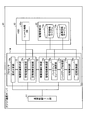
- FIG. 2 is a functional block diagram illustrating the configuration of the cloud cooperation server according to the first embodiment.
- the cloud cooperation server 10 includes a communication control interface unit (I / F unit) 11, an HDD (Hard Disk Drive) 12, and a processor 14.
- I / F unit communication control interface unit
- HDD Hard Disk Drive
- the communication control I / F unit 11 is an interface that controls communication with other devices and systems. For example, the communication control I / F unit 11 acquires storage resources and processor resources from the storage management server 20 in the cloud system 1 and acquires network resources from the network management server 30. Further, the communication control I / F unit 11 receives management information from another cloud system.
- the communication control I / F unit 11 transmits a resource release request to the storage management server 20 and the network management server 30, and receives a response to the resource release request from each management server. Further, the communication control I / F unit 11 receives various instructions transmitted from the user terminal 5.
- the HDD 12 stores a program executed by the processor 14 and has a work area for temporarily storing data and the like when each processing unit of the processor 14 executes processing.
- the HDD 12 has a resource information DB 12a and a management information DB 13.
- the resource information DB 12a is a database that stores processor resources, storage resources, and network resources used by users in the cloud system 1.
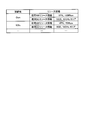
- FIG. 3 is a diagram illustrating an example of information stored in the resource information DB. As illustrated in FIG. 3, the resource information DB 12 a stores “connection destination, resource information (used NW resource information, used DC resource information)” in association with each other.
- connection destination stored here indicates an identifier for identifying a user who uses the resource.
- User NW resource information is information indicating a network resource used by the user, and is, for example, a line type or bandwidth used by the user.
- User DC resource information is information indicating storage resources and processor resources used by the user, such as the storage capacity used by the user, the number of CPU (Central Processing Unit) cores, and performance.
- FIG. 3 shows that “Own”, the owner user of the cloud system 1, uses VPN (Virtual Private Network) and 100 Mbps as a network. Further, “Own” indicates that 10 GB is used as a storage capacity and eight 10 GHz CPUs are used. Similarly, “ICSx” which is a user other than the owner user of the cloud system 1 uses VPN (Virtual Private Network), 70 Mbps as a network. Further, “ICSx” indicates that 8 GB is used as a storage capacity, and four 10 GHz CPUs are used.
- VPN Virtual Private Network
- the management information DB 13 is a database that stores management information received from a cloud system that has the cloud system 1 as a sub system, in other words, a primary system, and includes a management information table 13a and a linkage information table 13b.
- the management information table 13a stores management information related to a management information delegation source. That is, the management information table 13a stores resource information transmitted from a primary cloud system that handles the cloud system 1 as a secondary system.
- FIG. 4 is a diagram illustrating an example of information stored in the management information table. As illustrated in FIG. 4, the management information table 13 a stores “delegation source ICS name, delegation source user, delegation source address, periodic acquisition result, failure reference resource information” in association with each other.
- the delegation source ICS name stored here indicates the ICS name of the delegation source of the management information, in other words, the identifier of the cloud cooperation server of the primary cloud system.
- “Delegation source user” is an identifier of a user who uses the delegation source ICS name.
- “Delegation source address” is address information of the delegation source cloud system, such as a URL (Uniform Resource Locator).
- “Periodic acquisition result” indicates whether or not the management information can be periodically acquired from the delegation source and the latest acquisition date and time. For example, “OK” is stored when the management information can be periodically acquired. “NG” is stored when it has not been acquired.
- the “reference resource information at the time of failure” indicates the line type and bandwidth used by the transfer source user.
- the information stored here is extracted from the management information received from other ICSs.
- FIG. 4 shows that management information of the user “ICS5User05” who uses the ICS5 of “http: // ics5 / user05 /” is periodically acquired. Further, from the acquired management information, “the line type used by the ICS5 user 05 is VPN and the bandwidth is 100 Mbps”, “the storage used by the ICS5 user 05 is 5 GB, the CPU resource is 8 GHz, 8 It is extracted that it is a “core”. In the case of FIG. 4, since ICS5 and ICS3 are stored as delegation source ICS names, the cloud system 1 is a sub system of the two cloud systems.
- the cooperation information table 13b stores information received together with the management information of the delegation source when the delegation source is using resources in cooperation with other cloud systems. That is, the cooperation information table 13b stores the contents of the cooperation destination when the delegation source cloud system cooperates with another cloud system to provide a service to the user. As a result, even when system switching occurs, the service can be continued without hindering the cooperative relationship.
- FIG. 5 is a diagram illustrating an example of information stored in the cooperation information table. As shown in FIG. 5, the cooperation information table 13b associates “delegation source ICS, delegation source user, delegation source cooperation destination information (cooperation destination ICS information, cooperation destination NW resource information, cooperation destination DC resource information)”.
- the cooperation information table 13b associates “delegation source ICS, delegation source user, delegation source cooperation destination information (cooperation destination ICS information, cooperation destination NW resource information, cooperation destination DC resource information)”.
- the “delegation source ICS” stored here indicates the ICS name of the delegation source cooperating with another cloud, in other words, the identifier of the cloud cooperation server of the primary cloud system.
- “Delegation source user” is an identifier of a user who uses a delegation source ICS name linked with another cloud.
- the “cooperation destination ICS information” indicates information of other ICS with which the delegation source user is cooperating, and is, for example, the ICS or connection point of the cooperation destination.
- “Cooperation destination NW resource information” indicates network resources under other ICS with which the delegation source user is cooperating, such as line type, bandwidth, connection point, and the like.
- the “cooperation destination DC resource information” indicates storage resources or processor resources under other ICS with which the delegation source user cooperates, for example, storage in use, CPU resource amount, connection point, and the like.
- the user 05 of the ICS 5 indicates that the device having the IP (Internet Protocol) 6 under the ICS 6 of “http: // ics6” is linked and connected.
- the user 05 of the ICS 5 indicates that the ICS 6 uses a 3 Mbps VPN line as a network resource.
- the user 05 of the ICS5 uses the storage capacity of 2 GB as the storage resource in the ICS6, and uses two 2 GHz CPUs as the processor resource.
- the processor 14 is an electronic circuit such as a CPU that controls the entire cloud cooperation server 10, and includes a request analysis unit 14 a, an authority delegation request unit 15, and an authority delegation response unit 16.
- the processor 14 may include a CPU and a storage device (RAM, cache, etc.) that stores a program that performs each function and stores data necessary for processing.
- the request analysis unit 14a is a processing unit that receives various requests from the user terminal 5 and executes analysis. For example, the request analysis unit 14a determines whether the request received from the user terminal 5 is a management information transmission request, a setting or change of the transmission interval of management information, and a system switching execution request. Analyze contents. When the request is a management information transmission request or a setting or change of the management information transmission interval, the request analysis unit 14 a outputs the received content to the authority delegation request unit 15. In addition, when the request is a system switching execution request, the request analysis unit 14 a outputs the request to the authority delegation response unit 16.
- the authority delegation request unit 15 is a processing unit that executes a function as a primary cloud system, and includes a management information transmission unit 15a and a management information update unit 15b.
- the management information transmission unit 15a receives the transmission interval of management information from the request analysis unit 14a and the like and reaches the transmission trigger, “resource information (used NW resource information, used DC resource information)” stored in the resource information DB 12a. Is transmitted to the sub-system ICS as management information.
- the management information transmission unit 15a of the cloud system 1 sends the resource information “Own” and the resource information “ICSx” stored in the resource information DB 12a to the ICS 40 of the cloud system 2 as management information at intervals of 10 minutes. Send.
- the ICS of the transmission destination can be arbitrarily changed by the user.
- the management information transmitting unit 15a transmits the location of the user who uses the resource specified by the management information, address information, and the like together with the management information.
- the management information transmission unit 15a also transmits the linkage information.
- the management information update unit 15b is a processing unit that updates the resource information stored in the resource information DB 12a. For example, the management information update unit 15b periodically transmits an acquisition request for used resource information to the storage management server 20 and the network management server 30. And the management information update part 15b extracts resource information from the received response, when the response of the said acquisition request is received. Then, the management information update unit 15b updates the resource information stored in the resource information DB 12a with the extracted resource information. In addition, the management information update unit 15b receives cooperation information from a user or an administrator and stores it in the HDD 12 or the like.
- the authority delegation response unit 16 is a processing unit that executes a function as a subordinate cloud system, and includes a management information receiving unit 16a, a backup resource securing unit 16b, a backup processing unit 16c, a switching detection unit 16d, and a switching control unit 16e. Have.
- the management information receiving unit 16a is a processing unit that periodically receives management information and linkage information from the primary cloud system. For example, the management information receiving unit 16a extracts “delegation source ICS name, delegation source user, delegation source address” from the management information received from the primary cloud system, and stores them in the management information table 13a. Also, the management information receiving unit 16a extracts “resource information” from the management information received from the primary cloud system and stores it in the management information table 13a as “reference resource information at the time of failure”. In addition, the management information receiving unit 16a stores the location of the user extracted from the management information, address information, and the like in “delegation source address” and the like.
- the management information receiving unit 16a stores “OK” in the “periodic acquisition result” of the management information table 13a, and “management information” in the “update time”. Is stored. On the other hand, if the management information receiving unit 16a cannot receive the management information, it stores “NG” in the “periodic acquisition result” of the management information table 13a and also stores “ ⁇ ” in the “update time”. . Further, when the management information receiving unit 16a receives the cooperation information together with the management information, the management information receiving unit 16a extracts the “delegation source ICS name, the delegation source user, and the delegation source cooperation destination information” from the cooperation information, and stores them in the cooperation information table 13b. Store.
- the backup resource securing unit 16b is a processing unit that secures resources for backing up delegation source data. For example, based on the management information received by the management information receiving unit 16a, the backup resource securing unit 16b uses its own cloud to store storage resources for storing the data of the transfer source user and minimum network resources for receiving the data. Secure in the system.
- ICS5User05 in which “Delegation source ICS name” is “ICS5” will be described as an example.
- line type is VPN
- bandwidth is 100 Mbps
- storage capacity is 5 GB
- CPU resource is 8 GHz
- 8 cores as reference resource information at the time of failure.
- the backup resource securing unit 16b acquires that the transfer source user uses 5 GB as a data storage area. For this reason, the backup resource securing unit 16b performs securing of a resource capable of storing 5 GB, which is the data capacity used by the user “ICS5User05”, and securing of a network resource capable of transmitting and receiving 5 GB.
- the backup resource securing unit 16b transmits a request to secure a 5 GB capacity to the storage management server 20 to secure a 5 GB storable area in the cloud system 1. Further, the backup resource securing unit 16b secures the minimum bandwidth by transmitting a request for securing a minimum bandwidth capable of transmitting and receiving 5 GB of data to the network management server 30. Then, the backup resource securing unit 16b outputs to the backup processing unit 16c that the area and bandwidth for backing up data are secured. As an example, the storage management server 20 newly secures a 5 GB area in the DB server, and the network management server 30 secures a bandwidth of 10 Mbps for this DB server.
- the backup processing unit 16c is a processing unit that receives data from the delegation source using the network resource secured by the backup resource securing unit 16b and stores the data in the storage resource secured by the backup resource securing unit 16b.
- a description will be given using the example used in the description of the backup resource securing unit 16b.
- the backup processing unit 16c receives data from “ICS5” using a 10 Mbps line secured by the network management server 30. Then, the backup processing unit 16c stores the received data in the 5 GB area secured by the storage management server 20. Note that the backup processing unit 16c may perform regular backups, or may be executed according to an instruction from an operator or the like.
- the switching detection unit 16d is a processing unit that transmits a system switching instruction to the switching control unit 16e when the occurrence of system switching or recovery is detected. For example, when the switch detection unit 16d is notified that a request for system switching has been received from the request analysis unit 14a, or when “NG” is stored in the “periodic acquisition result” of the management information table 13a, the switch detection unit 16d Detect the occurrence of switching and recovery. Further, the switching detection unit 16d detects the occurrence of system switching or recovery when it is detected, for example, by SNMP (Simple Network Management Protocol) or monitoring software that a failure has occurred in the primary cloud system.
- SNMP Simple Network Management Protocol
- the switching control unit 16e is a processing unit that performs system switching and recovery. For example, when the user of the delegation source cloud system uses the cloud system 1, the switching control unit 16 e secures the network resource and the processor resource managed by the ICS of the delegation source cloud system in the cloud system 2. Then, the switching control unit 16e notifies the user that the system switching has been executed.
- the switching control unit 16 e transmits a request to secure eight 8 GHz CPUs to the storage management server 20 to secure eight 8 GHz CPUs in the cloud system 1. Similarly, the switching control unit 16e transmits a setting request to the network management server 30 so that a 100 Mbps VPN can be used, and secures a 100 Mbps VPN in the cloud system 1. Note that the network management server 30 may release the 10 Mbps bandwidth already reserved for data backup, or may reserve a 100 Mbps VPN including this 10 Mbps.
- the switching control unit 16e acquires, from the management information table 13a, the address information of the user corresponding to “ICS5User05” whose “delivery source ICS name” is “ICS5”. Then, the switching control unit 16e notifies the user of the IP address of the server that has newly assigned resources, with the acquired user address information as the destination. As a result, even when the system is switched, the user can continue to use the service used in the main system.
- FIG. 6 is a functional block diagram illustrating the configuration of the storage management server according to the first embodiment.
- the storage management server 20 includes a communication control I / F unit 21, an HDD 22, and a processor 23.
- the communication control I / F unit 21 is an interface that controls communication with other devices and systems. For example, the communication control I / F unit 21 transmits / receives various information to / from the cloud cooperation server 10, the network management server 30, and various servers in another cloud system. For example, the communication control I / F unit 21 receives a resource securing request from the cloud collaboration server 10 in the cloud system or transmits a resource securing result to the cloud collaboration server 10.
- the HDD 22 stores a program executed by the processor 23, and has a work area for temporarily storing data and the like when each processing unit of the processor 23 executes the process.
- the HDD 22 has a storage resource information DB 22a.
- the storage resource information DB 22a stores storage resources and processor resources that are managed by the storage management server 20 and are used by users in the cloud system 1.
- FIG. 7 is a diagram illustrating an example of information stored in the storage resource information DB. As illustrated in FIG. 7, the storage resource information DB 22a stores “connection destination and resource information” in association with each other.
- connection destination is an ICS identifier under which the storage management server 20 is subordinate, or an ICS identifier that collects information managed by the storage management server 20.
- “Resource information” is a storage resource or a processor resource in use. That is, the storage resource information DB 22a stores resource information provided to each ICS by each server in the same cloud system and resource information provided to a server of a cloud system different from the storage management server 20.
- the processor 23 is an electronic circuit such as a CPU that controls the overall control of the storage management server 20, and includes a resource collecting unit 23a and a resource securing unit 23b.
- the resource collection unit 23a collects resource information currently used from each server in the same cloud system as the storage management server 20, and stores it in the storage resource information DB 22a.
- the resource collection unit 23a stores a value obtained by summing the data capacities used in each server in the storage resource information DB 22a as a storage resource used by the user.
- the resource collection unit 23a acquires the CPU performance and the number of cores of each server, and stores the average performance and the total number of cores in the storage resource information DB 22a as processor resources used by the user.
- the resource collection unit 23a may collect the resources periodically, may be executed when the server resources are changed, or may be executed at an arbitrary timing.
- the resource securing unit 23b is a processing unit that secures storage resources and processor resources in its own cloud system in response to a request from the ICS. For example, when the resource securing unit 23b receives a backup storage resource securing request from the ICS 10, the resource securing unit 23b inquires each server in the cloud system 1 to which the device belongs to the availability status of the resource. Then, the resource securing unit 23b determines whether or not the resource requested from the ICS 10 can be secured, and returns the result to the ICS. Thereafter, the resource securing unit 23b reserves a storage resource for data backup in the cloud system 1 in accordance with an instruction from the ICS 10.
- the resource securing unit 23b when the resource securing unit 23b receives a processor resource securing request from the ICS 10 during system switching, the resource securing unit 23b inquires about the number of CPUs that can be allocated to each server in the cloud system 1 to which the own device belongs. Then, the resource securing unit 23b determines whether or not the resource requested from the ICS 10 can be secured, and returns the result to the ICS 10. Thereafter, the resource securing unit 23b allocates CPUs for the requested processor resources as usable CPUs in accordance with instructions from the ICS 10. The resource securing unit 23b updates information in the storage resource information DB 22a when a new resource is secured.
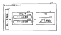
- FIG. 8 is a functional block diagram illustrating the configuration of the network management server according to the first embodiment.
- the network management server 30 includes a communication control I / F unit 31, an HDD 32, and a processor 33.
- the communication control I / F unit 31 is an interface that controls communication with other devices and systems. For example, the communication control I / F unit 31 transmits and receives various types of information to and from the cloud cooperation server 10, the storage management server 20, and various servers in the cloud system 1. For example, the communication control I / F unit 31 receives a resource securing request from the cloud collaboration server 10 in the cloud system or transmits a resource securing result to the cloud collaboration server 10.
- the HDD 32 stores a program executed by the processor 33 and has a work area for temporarily storing data and the like when each processing unit of the processor 33 executes processing.
- the HDD 32 has a network resource information DB 32a.
- the network resource information DB 32 a stores network resources that are managed by the network management server 30 and are used by users in the cloud system 1.
- FIG. 9 is a diagram illustrating an example of information stored in the network resource information DB. As shown in FIG. 9, the network resource information DB 32a stores “connection destination, resource information” in association with each other.
- connection destination is an ICS identifier under which the network management server 30 is subordinate, or an ICS identifier that collects information managed by the network management server 30.
- “Resource information” is a network resource in use. That is, the network management server 30 stores resource information provided to each ICS 10 by each server in the same cloud system 1 and resource information provided to a server of a cloud system different from the cloud to which the storage management server 20 belongs. To do.
- FIG. 9 it is shown that a VPN of 100 Mbps is allocated to the user in the same cloud system 1 as the ICS 10. In addition, it indicates that 10 Mbps VPN is provided to the user of the cloud system having the ICS 200.
- the processor 33 is an electronic circuit such as a CPU that controls the entire network management server 30, and includes a resource collection unit 33a and a resource securing unit 33b.
- the resource collection unit 33a collects network bandwidth and line information currently used in the same cloud system as the network management server 30, and stores it in the network resource information DB 32a. Note that the resource collection unit 33a may collect resources periodically or at an arbitrary timing.
- the resource securing unit 33 b is a processing unit that secures network resources in the cloud system 1 in response to a request from the ICS 10. For example, when the resource securing unit 33b receives a backup network resource securing request from the ICS 10, the resource securing unit 33b determines whether or not the resource requested by the ICS 10 can be secured, and returns the result to the ICS 10. Thereafter, the resource securing unit 33b allocates a network resource for data backup in accordance with an instruction from the ICS 10.
- the resource securing unit 33b receives a network resource securing request from the ICS 10 at the time of system switching, the resource securing unit 33b acquires the bandwidth that can be used in the entire cloud system 1 and the bandwidth that is currently used. Then, the resource securing unit 33b determines whether or not the resource requested from the ICS 10 can be secured, and returns the result to the ICS 10. Thereafter, the resource securing unit 33b allocates the requested network resource in accordance with an instruction from the ICS 10. Note that the resource securing unit 33b updates the information in the network resource information DB 32a when a resource is newly secured.
- FIGS. 10 and 11 are sequence diagrams illustrating the flow of processing according to the first embodiment.
- the cloud system 1 shown in FIG. 1 will be described as a primary system
- the cloud system 2 will be described as a secondary system.
- the authority delegation destination is specified based on the content designated by the administrator or the user (S102).
- the management information transmission part 15a of ICS10 acquires management information from resource information DB12a (S103), and transmits management information to ICS40 with an authority transfer request (S104).
- the management information receiving unit 16a of the ICS 40 of the secondary cloud system 2 When the management information receiving unit 16a of the ICS 40 of the secondary cloud system 2 receives the authority delegation request together with the management information from the ICS 10, it registers the received management information in the management information DB (S105). Then, the management information receiving unit 16a of the ICS 40 transmits an authority delegation response to the ICS 10 as a response to the authority delegation request (S106).
- the authority delegation request unit 15 of the ICS 10 Upon receiving the authority delegation response, the authority delegation request unit 15 of the ICS 10 transmits a backup start request to the ICS 40 (S107).
- the backup resource securing unit 16b of the ICS 40 that has received the backup start request transmits a request for inquiring whether the backup resource information specified based on the management information can be secured to the NW-OPS 60 and the DC-OPS 50 (S108). ).
- the backup resource securing unit 16b of the ICS 40 transmits to the DC-OPS 50 whether or not a capacity sufficient to store data can be secured as backup resource information.
- the backup resource securing unit 16b of the ICS 40 inquires of the NW-OPS 60 whether or not a minimum bandwidth sufficient to receive data can be secured.
- the resource securing unit 33b of the NW-OPS 60 that has received this request secures the minimum bandwidth necessary for data backup in consideration of the bandwidth that can be used in the entire cloud system and the bandwidth that is currently used. It responds to the ICS 40 whether or not it is possible (S109). Similarly, the resource securing unit 23b of the DC-OPS 50 obtains a usable storage capacity from each server in the cloud system, and responds to the ICS 40 whether or not an area necessary for data backup can be secured (S110). . Here, it is assumed that both responded that they can be secured.
- the backup resource securing unit 16b of the ICS 40 that has received a response that can be secured from both management servers transmits a backup resource securing request to the NW-OPS 60 and the DC-OPS 50 (S111).
- the resource securing unit 33b of the NW-OPS 60 sets a bandwidth that allows backup data to be transmitted and received between the primary cloud system 1 and the secondary cloud system 2, and transmits a resource information securing response to the ICS 40 (S112). ).
- the resource securing unit 23b of the DC-OPS 50 secures an area necessary for data backup in each server in the loud system and transmits a resource information securing response to the ICS 40 (S113).
- the backup resource securing unit 16b of the ICS 40 that has received the resource securing response from both management servers transmits a response to the backup start request received in S107 to the ICS 10 (S114). Upon receiving this response, the processor of the ICS 10 transmits a backup start instruction to the DC-OPS 20 (S115).
- data backup is started between the DC-OPS 20 of the primary cloud system 1 and the secondary cloud system 2 (S116). That is, the backup processing unit 16c of the ICS 40 receives data from the DC-OPS 20 via the minimum bandwidth allocated for data backup and stores it in the area allocated for data backup.
- the switching detection unit 16d of the ICS 40 of the secondary cloud system 2 detects a recovery instruction due to a failure of the primary cloud system 1 or the like (S201). Then, the switching control unit 16e of the ICS 40 reads management information from the management information table 13a of the management information DB 13 (S202). Then, the switching control unit 16e of the ICS 40 refers to the reference resource information at the time of failure, analyzes the resource information used by the user in the primary cloud system 1, and specifies the resource information necessary for recovery (S203). .
- the switching control unit 16e of the ICS 40 transmits a request for securing resource information necessary for recovery to each of the NW-OPS 60 and the DC-OPS 50 (S204).
- the resource securing unit 33b of the NW-OPS 60 that has received this request secures the bandwidth required for the requested recovery in consideration of the bandwidth that can be used in the entire cloud system 2 and the bandwidth that is currently used. It responds to the ICS 40 whether or not it is possible (S205).
- the resource securing unit 23b of the DC-OPS 50 obtains the number of usable processors from each server in the cloud system 2 and informs the ICS 40 whether or not a processor necessary for the requested recovery can be secured. A response is made (S206). Here, it is assumed that both responded that they can be secured.
- the switching control unit 16e of the ICS 40 that has received a response that can be secured from both management servers transmits a resource securing request for recovery to the NW-OPS 60 and the DC-OPS 50 (S207).
- the resource securing unit 33b of the NW-OPS 60 sets the requested bandwidth between the primary cloud system 1 and the secondary cloud system 2, and transmits a necessary resource securing response to the ICS 40 (S208).
- the resource securing unit 23b of the DC-OPS 50 secures the requested CPU in each server in the cloud system 2, and transmits a necessary resource securing response to the ICS 40 (S209).
- the switching control unit 16e of the ICS 40 that has received the resource securing response from both management servers transmits the securing response to the user terminal 5 (S210).
- the destination of the user terminal 5 is stored in, for example, the management information table 13a.
- the securement response transmitted here includes, for example, server address information and application information of the cloud system 2 to be used in the future by the user of the cloud system 1.
- the backup destination can be arbitrarily changed by providing the cloud cooperation server.
- the management information (ConfigList) sent when the user performs authority delegation can specify the amount of resources required for backup and the quality of resources.
- each ICS analyzes a user request from the management information and returns the resource information as management information to the sending ICS.
- the secondary system is operated only for data backup with the minimum required resources, and management function is acquired by delegating authority to function as a primary system in the event of a failure, thereby reducing costs and continuing service in the event of a failure. Can be made.
- FIG. 12 is a diagram illustrating an overall configuration example of a system according to the second embodiment. As shown in FIG. 12, this system includes a cloud system (primary system) 1, a cloud system (secondary system) 2, another cloud system 70, another cloud system 80, and a user terminal 5. Note that the device configuration of each cloud system is the same as that shown in FIG.
- resources are transferred from the cloud system (primary system) 1 to the cloud system (secondary system) 2, and the cloud system (secondary system) 2 is used in the cloud system (primary system) 1.
- FIG. 13 is a flowchart of data backup executed by the cloud system (secondary system) according to the second embodiment. As shown in FIG. 13, when the management information receiving unit 16a of the ICS 40 of the cloud system 2 receives the management information from the cloud system 1 (Yes in S301), the received management information is registered in the management information table 13a of the management information DB 13. (S302).
- the backup resource securing unit 16b of the ICS 40 receives the backup start request from the cloud system 1 (Yes in S303), it specifies a resource for data backup (S304).
- the backup resource securing unit 16b transmits the specified backup resource securing request to each of the DC-OPS 50 and NW-OPS 60 in the cloud system 2 (S305). Subsequently, the backup resource securing unit 16b receives a response indicating whether or not resources can be secured from each of the DC-OPS 50 and the NW-OPS 60 (S306).
- the backup resource securing unit 16b determines that the resource can be secured based on this response (Yes in S307), the backup resource securing unit 16b reserves the backup resource in each of the DC-OPS 50 and the NW-OPS 60 (S308). Then, the backup resource securing unit 16b transmits a backup start response to the cloud system 1 (S309). Thereafter, the backup processing unit 16c starts data backup of the cloud system 1 using only the reserved data backup resources (S310).
- the backup resource securing unit 16b determines that the resource cannot be secured based on the response received in S306 (No in S307), the backup resource securing unit 16b identifies an unsecured resource (S311). For example, the backup resource securing unit 16b receives a resource capacity that can be secured from each management server together with a response. Then, the backup resource securing unit 16b calculates the difference between the data capacity identified from the management information and the securable capacity received from the DC-OPS 40, and identifies the calculated difference as an unsecured resource. The bandwidth can be similarly processed.
- the backup resource securing unit 16b identifies the ICS of the other cloud system 70 to be the next delegation destination according to the priority as the delegation destination (S312), and the backup resources for the unallocated backup resources are identified in the identified ICS.
- a securing request is transmitted (S313).
- the ICS of the other cloud system 70 receives resources that can be secured from each management server in its own cloud system, identifies the resources that can be secured, and responds to the ICS 40.
- the backup resource securing unit 16b receives a response indicating whether or not resources can be secured from the ICS of the other cloud system 70 (S314).
- the backup resource securing unit 16b determines that the resource can be secured based on this response (Yes at S315), the backup resource securing unit 16b executes the processing after S308. On the other hand, when the backup resource securing unit 16b determines that the resource cannot be secured based on this response (No at S315), the backup resource securing unit 16b executes the processes after S311 on the other cloud system 80 having the next highest priority.
- the management information receiving unit 16a of the ICS 40 receives the management information from the delegation source ICS 10 (Yes in S316), and when the received management information is updated from the previously received management information (Yes in S317). ), The management information DB 13 is updated (S318). And ICS40 performs the process after S304 based on the updated management information.
- FIG. 14 is a flowchart of system switching executed by the cloud system (secondary system) according to the second embodiment.
- the switching detection unit 16d of the ICS 40 of the cloud system 2 detects the occurrence of recovery (Yes at S401)
- the switching control unit 16e of the cloud system 2 reads management information from the management information table 13a (S402). .
- the switching control unit 16e of the cloud system 2 refers to the reference resource information at the time of failure, analyzes the resource information used by the user in the primary cloud system 1, and identifies the resource information necessary for recovery (S403).
- the switching control unit 16e of the ICS 40 transmits a request for securing resource information necessary for recovery to each of the NW-OPS 60 and the DC-OPS 50 (S404). Thereafter, the switching control unit 16e receives a response indicating whether or not resources necessary for recovery can be secured from each of the DC-OPS 50 and the NW-OPS 60 (S405).
- the switching control unit 16e of the ICS 40 determines that the resources necessary for recovery can be secured (Yes in S406), and instructs the DC-OPS 50 and the NW-OPS 60 to secure the recovery resources. Is transmitted (S407).
- the switching control unit 16e of the ICS 40 determines based on the response received in S405 that the resources necessary for recovery cannot be secured (No in S406), it identifies unsecured resources (S408). For example, the switching control unit 16e receives a resource capacity that can be secured from each management server together with a response. Then, the switching control unit 16e calculates a difference between the number of processors specified from the management information and the number of processors that can be secured received from the DC-OPS 40, and identifies the calculated difference as an unsecured processor resource. The bandwidth can be similarly processed.
- the switching control unit 16e identifies the ICS of the other cloud system 70 to be the next delegation destination in accordance with the priority as the delegation destination (S409), and secures unreserved recovery resources for the identified ICS A request is transmitted (S410).
- the ICS of the other cloud system 70 receives resources that can be secured from each management server in its own cloud system, identifies the resources that can be secured, and responds to the ICS 40.
- the switching control unit 16e receives a response indicating whether or not resources can be secured from the ICS of the other cloud system 70 (S411). If it is determined that the resource can be secured based on this response (Yes in S412), the switching control unit 16e executes the processes after S407. On the other hand, when it is determined that the resource cannot be secured based on this response (No in S412), the switching control unit 16e executes the processes after S408 on the other cloud system 80 having the next highest priority.
- the switching control unit 16e that secured the recovery resource receives a response indicating that the resource has been secured from the management server or ICS that secures the recovery lease (Yes in S413), the user terminal 5 transmits necessary information (S414).
- the system switching is executed without making the user aware of the system switching, and the service used in the cloud system 1 is continued.
- the secondary ICS receives information on the user who uses the primary cloud system together with the management information from the primary ICS.
- the user information received here includes, for example, a user identifier, an IP address, a location, and the like.
- the sub-system ICS uses this user information to transmit a notification after the system switching to the user.
- the primary system can specify a delegation destination or an unsecured resource securing destination based on a priority designated in advance.
- This priority can be arbitrarily set by an administrator or a user.
- the priority can be set in order of unused resources.
- Delegation cancellation For example, when the secondary system receives a delegation cancellation notification from the primary system, it responds to the request source with a cancellation response and deletes the primary management information from the management information DB. By doing so, the relationship between the delegation destination and the delegation source can be deleted.
- each component of each illustrated apparatus is functionally conceptual and does not necessarily need to be physically configured as illustrated. That is, the specific form of distribution / integration of each device is not limited to that shown in the figure. That is, all or a part of them can be configured to be functionally or physically distributed / integrated in arbitrary units according to various loads or usage conditions. Further, all or any part of each processing function performed in each device may be realized by a CPU and a program analyzed and executed by the CPU, or may be realized as hardware by wired logic.
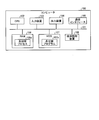
- FIG. 15 is a diagram illustrating an example of a hardware configuration of a computer that executes a system switching program.
- the computer 100 includes a CPU 102, an input device 103, an output device 104, a communication interface 105, a medium reading device 106, an HDD (Hard Disk Drive) 107, and a RAM (Random Access Memory) 108. 15 are connected to each other via a bus 101.
- the input device 103 is a mouse or a keyboard
- the output device 104 is a display or the like
- the communication interface 105 is an interface such as a NIC (Network Interface Card).
- the HDD 107 stores each DB shown in FIG. 2 together with the system switching program 107a.
- the HDD 107 is taken as an example, but various programs are stored in other computer-readable recording media such as ROM (Read Only Memory), RAM, CD-ROM, etc., and are read by the computer. Also good.
- ROM Read Only Memory
- RAM Random Only Memory
- CD-ROM Compact Only Memory
- a recording medium may be arranged in a remote place, and the computer may acquire and use the program by accessing the storage medium. At that time, the acquired program may be stored in a recording medium of the computer itself and used.
- the CPU 102 reads the system switching program 107a and develops it in the RAM 108, thereby operating the system switching process 108a that executes each function described in FIG. That is, the system switching process 108a performs the same functions as those of the request analysis unit 14a, the management information transmission unit 15a, and the management information update unit 15b described in FIG. Further, the system switching process 108a performs the same functions as the management information receiving unit 16a, the backup resource securing unit 16b, the backup processing unit 16c, the switching detection unit 16d, and the switching control unit 16e described in FIG. As described above, the computer 100 operates as an information processing apparatus that executes the system switching method by reading and executing the program.
- the computer 100 can realize the same function as the above-described embodiment by reading the system switching program from the recording medium by the medium reading device 106 and executing the read system switching program.
- the program referred to in the other embodiments is not limited to being executed by the computer 100.
- the present invention can be similarly applied to a case where another computer or server executes the program, or a case where these programs cooperate to execute the program.
Landscapes
- Engineering & Computer Science (AREA)
- Theoretical Computer Science (AREA)
- Computer Networks & Wireless Communication (AREA)
- Signal Processing (AREA)
- Quality & Reliability (AREA)
- Physics & Mathematics (AREA)
- General Engineering & Computer Science (AREA)
- General Physics & Mathematics (AREA)
- Information Retrieval, Db Structures And Fs Structures Therefor (AREA)
- Hardware Redundancy (AREA)
Abstract
Selon l'invention, un dispositif de sous-administration reçoit, à partir d'un système primaire, des informations d'administration comprenant des informations de chaque type de ressources qu'un utilisateur utilise sur le système primaire : des ressources de processeur, des ressources de stockage et des ressources de réseau. Le dispositif de sous-administration attribue, à l'intérieur du sous-système, sur la base des informations d'administration reçues, des ressources de stockage qui stockent des données de l'utilisateur que le système primaire conserve, et des ressources de réseau minimales qui reçoivent les données. Le dispositif de sous-administration reçoit les données à partir du système primaire à l'aide des ressources de réseau attribuées, et stocke celles-ci dans les ressources de stockage attribuées. Lorsque l'utilisateur est amené à utiliser un sous-système, le dispositif de sous-administration attribue, sur la base des informations d'administration reçues, les ressources de réseau et les ressources de processeur à l'intérieur du sous-système que l'utilisateur utilise sur le système primaire.
Priority Applications (2)
| Application Number | Priority Date | Filing Date | Title |
|---|---|---|---|
| PCT/JP2011/064585 WO2012176337A1 (fr) | 2011-06-24 | 2011-06-24 | Système de traitement d'informations, procédé de commande de système de traitement d'informations, dispositif d'administration et programme de commutation de système |
| US14/105,161 US20140101320A1 (en) | 2011-06-24 | 2013-12-12 | Information processing system, control method, management apparatus and computer-readable recording medium |
Applications Claiming Priority (1)
| Application Number | Priority Date | Filing Date | Title |
|---|---|---|---|
| PCT/JP2011/064585 WO2012176337A1 (fr) | 2011-06-24 | 2011-06-24 | Système de traitement d'informations, procédé de commande de système de traitement d'informations, dispositif d'administration et programme de commutation de système |
Related Child Applications (1)
| Application Number | Title | Priority Date | Filing Date |
|---|---|---|---|
| US14/105,161 Continuation US20140101320A1 (en) | 2011-06-24 | 2013-12-12 | Information processing system, control method, management apparatus and computer-readable recording medium |
Publications (1)
| Publication Number | Publication Date |
|---|---|
| WO2012176337A1 true WO2012176337A1 (fr) | 2012-12-27 |
Family
ID=47422208
Family Applications (1)
| Application Number | Title | Priority Date | Filing Date |
|---|---|---|---|
| PCT/JP2011/064585 Ceased WO2012176337A1 (fr) | 2011-06-24 | 2011-06-24 | Système de traitement d'informations, procédé de commande de système de traitement d'informations, dispositif d'administration et programme de commutation de système |
Country Status (2)
| Country | Link |
|---|---|
| US (1) | US20140101320A1 (fr) |
| WO (1) | WO2012176337A1 (fr) |
Cited By (5)
| Publication number | Priority date | Publication date | Assignee | Title |
|---|---|---|---|---|
| JPS5990578A (ja) * | 1982-11-17 | 1984-05-25 | ヤマハ株式会社 | ゴルフ用ウツドクラブヘツドの製法 |
| JP2015092314A (ja) * | 2013-11-08 | 2015-05-14 | 株式会社日立製作所 | バックアップ管理システムおよびバックアップ管理方法 |
| JP2015170251A (ja) * | 2014-03-10 | 2015-09-28 | 富士通株式会社 | 冗長処理方法、冗長処理システム及び情報処理装置 |
| CN105593835A (zh) * | 2013-10-03 | 2016-05-18 | 慧与发展有限责任合伙企业 | 通过主云服务管理器管理多个二级云 |
| CN113572159A (zh) * | 2021-07-28 | 2021-10-29 | 深圳供电局有限公司 | 一种基于电网调控系统知识推理的线路跳闸事故处置系统 |
Families Citing this family (2)
| Publication number | Priority date | Publication date | Assignee | Title |
|---|---|---|---|---|
| KR102604892B1 (ko) | 2014-09-17 | 2023-11-21 | 크라이프토그라피 리서치, 인코포레이티드 | 집적 회로를 위한 상이한 엔티티들의 특권들의 관리 |
| WO2017195356A1 (fr) * | 2016-05-13 | 2017-11-16 | 三菱電機株式会社 | Dispositif, procédé et programme de traitement de données |
Citations (4)
| Publication number | Priority date | Publication date | Assignee | Title |
|---|---|---|---|---|
| JP2000341285A (ja) * | 1999-05-26 | 2000-12-08 | Nippon Telegr & Teleph Corp <Ntt> | アドレス変換テーブル書き換えによる予備系立ち上げ方法 |
| JP2001209627A (ja) * | 2000-01-27 | 2001-08-03 | Hitachi Ltd | 情報処理システム |
| JP2005250840A (ja) * | 2004-03-04 | 2005-09-15 | Nomura Research Institute Ltd | 耐障害システムのための情報処理装置 |
| WO2006040811A1 (fr) * | 2004-10-12 | 2006-04-20 | Fujitsu Limited | Programme de traitement d'echange de ressources et procede de traitement d'echange de ressources |
Family Cites Families (4)
| Publication number | Priority date | Publication date | Assignee | Title |
|---|---|---|---|---|
| US20070118389A1 (en) * | 2001-03-09 | 2007-05-24 | Shipon Jacob A | Integrated teleconferencing system |
| JP5062845B2 (ja) * | 2008-06-30 | 2012-10-31 | 日本電信電話株式会社 | 経路切替方法、サーバ装置、境界ノード装置、経路切替システム及び経路切替プログラム |
| US20120158553A1 (en) * | 2010-12-17 | 2012-06-21 | Yodchai Sudhidhanakul | Method and System for Inventory Management Over a Peer-To-Peer Network |
| JP5545888B2 (ja) * | 2011-06-14 | 2014-07-09 | 日本電信電話株式会社 | ネットワークシステムおよびこれに用いるサーバシステム |
-
2011
- 2011-06-24 WO PCT/JP2011/064585 patent/WO2012176337A1/fr not_active Ceased
-
2013
- 2013-12-12 US US14/105,161 patent/US20140101320A1/en not_active Abandoned
Patent Citations (4)
| Publication number | Priority date | Publication date | Assignee | Title |
|---|---|---|---|---|
| JP2000341285A (ja) * | 1999-05-26 | 2000-12-08 | Nippon Telegr & Teleph Corp <Ntt> | アドレス変換テーブル書き換えによる予備系立ち上げ方法 |
| JP2001209627A (ja) * | 2000-01-27 | 2001-08-03 | Hitachi Ltd | 情報処理システム |
| JP2005250840A (ja) * | 2004-03-04 | 2005-09-15 | Nomura Research Institute Ltd | 耐障害システムのための情報処理装置 |
| WO2006040811A1 (fr) * | 2004-10-12 | 2006-04-20 | Fujitsu Limited | Programme de traitement d'echange de ressources et procede de traitement d'echange de ressources |
Cited By (7)
| Publication number | Priority date | Publication date | Assignee | Title |
|---|---|---|---|---|
| JPS5990578A (ja) * | 1982-11-17 | 1984-05-25 | ヤマハ株式会社 | ゴルフ用ウツドクラブヘツドの製法 |
| CN105593835A (zh) * | 2013-10-03 | 2016-05-18 | 慧与发展有限责任合伙企业 | 通过主云服务管理器管理多个二级云 |
| US10462018B2 (en) | 2013-10-03 | 2019-10-29 | Hewlett Packard Enterprise Development Lp | Managing a number of secondary clouds by a master cloud service manager |
| JP2015092314A (ja) * | 2013-11-08 | 2015-05-14 | 株式会社日立製作所 | バックアップ管理システムおよびバックアップ管理方法 |
| JP2015170251A (ja) * | 2014-03-10 | 2015-09-28 | 富士通株式会社 | 冗長処理方法、冗長処理システム及び情報処理装置 |
| US9652342B2 (en) | 2014-03-10 | 2017-05-16 | Fujitsu Limited | Redundancy processing method and system, and information processing apparatus thereof |
| CN113572159A (zh) * | 2021-07-28 | 2021-10-29 | 深圳供电局有限公司 | 一种基于电网调控系统知识推理的线路跳闸事故处置系统 |
Also Published As
| Publication number | Publication date |
|---|---|
| US20140101320A1 (en) | 2014-04-10 |
Similar Documents
| Publication | Publication Date | Title |
|---|---|---|
| US8015275B2 (en) | Computer product, method, and apparatus for managing operations of servers | |
| CN103677967B (zh) | 一种数据库的远程数据服务系统及任务调度方法 | |
| WO2012176337A1 (fr) | Système de traitement d'informations, procédé de commande de système de traitement d'informations, dispositif d'administration et programme de commutation de système | |
| CN100536417C (zh) | 网格许可服务器和容错网格系统及使用方法 | |
| US8271632B2 (en) | Remote access providing computer system and method for managing same | |
| US20150347246A1 (en) | Automatic-fault-handling cache system, fault-handling processing method for cache server, and cache manager | |
| JP4677482B2 (ja) | アクセス振分システム、サーバ装置、共通管理装置、アクセス振分装置、アクセス振分方法、及び、コンピュータプログラム | |
| JP5352367B2 (ja) | 仮想マシン起動端末および仮想マシン起動プログラム | |
| JP2005501335A (ja) | コンピュータ・リソースの負荷をコンピュータの間で分散する方法及びシステム | |
| JP2006285316A (ja) | サーバ性能計測方法及びサーバ性能計測システム並びにこれらに用いるコンピュータプログラム | |
| JP2013218449A (ja) | クラウドコンピューティングシステム | |
| JPH09293059A (ja) | 分散システム及びその運用管理方法 | |
| CN116820686B (zh) | 物理机的部署方法、虚拟机和容器统一监控的方法及装置 | |
| CN110213364B (zh) | 快递柜监控方法、系统、存储介质和设备 | |
| JPWO2012176337A1 (ja) | 情報処理システム、情報処理システムの制御方法、管理装置および系切替プログラム | |
| KR102367262B1 (ko) | 미들웨어를 이용한 모니터링 방법, 장치 및 시스템 | |
| US20230146880A1 (en) | Management system and management method | |
| JP6364203B2 (ja) | システムの稼働状態を監視する監視サーバ及び監視サーバの制御方法 | |
| JP2014123172A (ja) | 計算機システム、及びシステム管理方法 | |
| JP6394620B2 (ja) | サーバ管理システム、サーバ、サーバ管理方法およびサービスプロセッサ | |
| CN119011685B (zh) | 一种微服务热重启方法 | |
| JPH06274432A (ja) | 分散計算機システム管理方式およびその管理方法 | |
| JP5593260B2 (ja) | 移動要求装置、移動要求方法、移動要求プログラム | |
| JP6745767B2 (ja) | 通信サービスシステムおよび系切り戻し方法 | |
| JP2011248737A (ja) | タスク引継プログラム、処理装置及びコンピュータ・システム |
Legal Events
| Date | Code | Title | Description |
|---|---|---|---|
| 121 | Ep: the epo has been informed by wipo that ep was designated in this application |
Ref document number: 11868105 Country of ref document: EP Kind code of ref document: A1 |
|
| ENP | Entry into the national phase |
Ref document number: 2013521402 Country of ref document: JP Kind code of ref document: A |
|
| NENP | Non-entry into the national phase |
Ref country code: DE |
|
| 122 | Ep: pct application non-entry in european phase |
Ref document number: 11868105 Country of ref document: EP Kind code of ref document: A1 |