WO2012176337A1 - 情報処理システム、情報処理システムの制御方法、管理装置および系切替プログラム - Google Patents
情報処理システム、情報処理システムの制御方法、管理装置および系切替プログラム Download PDFInfo
- Publication number
- WO2012176337A1 WO2012176337A1 PCT/JP2011/064585 JP2011064585W WO2012176337A1 WO 2012176337 A1 WO2012176337 A1 WO 2012176337A1 JP 2011064585 W JP2011064585 W JP 2011064585W WO 2012176337 A1 WO2012176337 A1 WO 2012176337A1
- Authority
- WO
- WIPO (PCT)
- Prior art keywords
- resource
- resources
- information
- unit
- secured
- Prior art date
- Legal status (The legal status is an assumption and is not a legal conclusion. Google has not performed a legal analysis and makes no representation as to the accuracy of the status listed.)
- Ceased
Links
Images


Classifications
-
- H—ELECTRICITY
- H04—ELECTRIC COMMUNICATION TECHNIQUE
- H04L—TRANSMISSION OF DIGITAL INFORMATION, e.g. TELEGRAPHIC COMMUNICATION
- H04L47/00—Traffic control in data switching networks
- H04L47/70—Admission control; Resource allocation
- H04L47/78—Architectures of resource allocation
-
- G—PHYSICS
- G06—COMPUTING OR CALCULATING; COUNTING
- G06F—ELECTRIC DIGITAL DATA PROCESSING
- G06F11/00—Error detection; Error correction; Monitoring
- G06F11/07—Responding to the occurrence of a fault, e.g. fault tolerance
- G06F11/16—Error detection or correction of the data by redundancy in hardware
- G06F11/20—Error detection or correction of the data by redundancy in hardware using active fault-masking, e.g. by switching out faulty elements or by switching in spare elements
- G06F11/202—Error detection or correction of the data by redundancy in hardware using active fault-masking, e.g. by switching out faulty elements or by switching in spare elements where processing functionality is redundant
- G06F11/2038—Error detection or correction of the data by redundancy in hardware using active fault-masking, e.g. by switching out faulty elements or by switching in spare elements where processing functionality is redundant with a single idle spare processing component
-
- G—PHYSICS
- G06—COMPUTING OR CALCULATING; COUNTING
- G06F—ELECTRIC DIGITAL DATA PROCESSING
- G06F11/00—Error detection; Error correction; Monitoring
- G06F11/07—Responding to the occurrence of a fault, e.g. fault tolerance
- G06F11/16—Error detection or correction of the data by redundancy in hardware
- G06F11/20—Error detection or correction of the data by redundancy in hardware using active fault-masking, e.g. by switching out faulty elements or by switching in spare elements
- G06F11/202—Error detection or correction of the data by redundancy in hardware using active fault-masking, e.g. by switching out faulty elements or by switching in spare elements where processing functionality is redundant
- G06F11/2048—Error detection or correction of the data by redundancy in hardware using active fault-masking, e.g. by switching out faulty elements or by switching in spare elements where processing functionality is redundant where the redundant components share neither address space nor persistent storage
Definitions
- the present invention relates to an information processing system, a control method for the information processing system, a management device, and a system switching program.
- the primary data is copied to the standby system, and the standby system is operated as a new primary system. In this way, even when the service cannot be provided by the main system, the service is continued in the standby system.
- the disclosed technology has been made in view of the above, and an information processing system, a control method for the information processing system, a management device, and system switching that can continue services while reducing the cost of system redundancy
- the purpose is to provide a program.
- the present invention provides a management unit for a first system, a collection unit that collects processor resources, storage resources, and network resources used by a user in the first system
- the management device of the first system includes a transmission unit that transmits management information including information on various resources collected by the collection unit to the second system.
- the management apparatus of the second system includes a receiving unit that receives the management information from the first system.
- the management device of the second system has a first securing unit.
- the first securing unit includes a storage resource for storing the user data held by the first system and a minimum network resource for receiving the data based on the management information received by the receiving unit. Secure in the second system.
- the management device of the second system receives the data from the first system using the network resource secured by the first securing unit, and stores the data in the storage resource secured by the first securing unit.
- the management device of the second system has a second securing unit. When the second securing unit causes the user to use the second system, based on the received management information, the second securing unit collects network resources and processor resources collected by the management device of the first system. Secure in the system of 2.
- the information processing system, the information processing system control method, the management apparatus, and the system switching program according to the present invention have an effect that the service can be continued while reducing the cost for system redundancy.
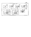
- FIG. 1 is a diagram illustrating an example of the overall configuration of a system according to the first embodiment.
- FIG. 2 is a functional block diagram illustrating the configuration of the cloud cooperation server according to the first embodiment.
- FIG. 3 is a diagram illustrating an example of information stored in the resource information DB.
- FIG. 4 is a diagram illustrating an example of information stored in the management information table.
- FIG. 5 is a diagram illustrating an example of information stored in the cooperation information table.
- FIG. 6 is a functional block diagram illustrating the configuration of the storage management server according to the first embodiment.
- FIG. 7 is a diagram illustrating an example of information stored in the storage resource information DB.
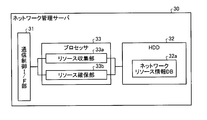
- FIG. 8 is a functional block diagram illustrating the configuration of the network management server according to the first embodiment.
- FIG. 1 is a diagram illustrating an example of the overall configuration of a system according to the first embodiment.
- FIG. 2 is a functional block diagram illustrating the configuration of the cloud cooperation server according to the first embodiment.
- FIG. 3 is
- FIG. 9 is a diagram illustrating an example of information stored in the network resource information DB.
- FIG. 10 is a sequence diagram illustrating the flow of processing according to the first embodiment.
- FIG. 11 is a sequence diagram illustrating the flow of processing according to the first embodiment.
- FIG. 12 is a diagram illustrating an overall configuration example of a system according to the second embodiment.
- FIG. 13 is a flowchart of data backup executed by the cloud system (secondary system) according to the second embodiment.
- FIG. 14 is a flowchart of system switching executed by the cloud system (secondary system) according to the second embodiment.
- FIG. 15 is a diagram illustrating an example of a hardware configuration of a computer that executes a system switching program.
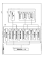
- FIG. 1 is a diagram illustrating an example of the overall configuration of a system according to the first embodiment. As shown in FIG. 1, this system includes a cloud system 1, a cloud system 2, and a user terminal 5, and each system and each system and the user terminal 5 are connected via a network such as the Internet.
- the user terminal 5 is a user terminal that uses the cloud system 1.
- the cloud system 1 is a system used by the user of the user terminal 5.
- the cloud system 1 includes a gateway device (GW) 1 a and a cloud cooperation server (ICS: Inter Cloud Server) 10.
- the cloud system 1 includes a storage management server (DC-OPS: Data Center Operation System) 20, a network management server (NW-OPS: Network Operation System) 30, and other servers.
- DC-OPS Data Center Operation System
- NW-OPS Network Operation System
- the gateway device 1 a is a network device that controls communication between the cloud system 1 and another cloud system or the user terminal 5.
- the ICS 10 is a server device that receives instructions such as system switching from the user terminal 5 and performs various controls.
- the ICS 10 manages processor resources, storage resources, and network resources used by the user in the cloud system 1.
- the ICS 10 collects processor resources and storage resources from the DC-OPS 20 and collects and manages network resources from the NW-OPS 30.
- the DC-OPS 20 is a server device that centrally manages storage resources and processor resources used by users in the cloud system 1. For example, the DC-OPS 20 collects the data capacity used by the user, the number of processors, and the like from each server in the cloud system 1.
- the NW-OPS 30 is a server device that centrally manages network resources used by users in the cloud system 1. For example, the NW-OPS 30 collects the form of the network used by the user, the bandwidth allocated to the user, and the like from each server in the cloud system 1.
- Various servers (expressed as other servers in the above) are server devices used by users, such as Web servers and DB (DataBase) servers.
- the cloud system 2 is a system used by users other than the user terminal 5. It includes a gateway device (GW) 2a, a cloud cooperation server (ICS) 40, a storage management server (DC-OPS) 50, a network management server (NW-OPS) 60, and other servers. Since each device included in the cloud system 2 performs the same function as the device included in the cloud system 1, detailed description thereof is omitted.
- GW gateway device
- ICS cloud cooperation server
- DC-OPS storage management server
- NW-OPS network management server
- the ICS 10 of the cloud system 1 collects processor resources, storage resources, and network resources used by the user in the cloud system 1 and transmits management information including information on the collected resources to the cloud system 2.
- the ICS 40 of the cloud system 2 receives management information from the cloud system 1. Then, the ICS 40 secures in the cloud system 2 storage resources for storing user data held by the cloud system 1 and minimum network resources for receiving data, based on the received management information. Subsequently, the ICS 40 receives data from the cloud system 1 using the reserved network resource and stores the data in the reserved minimum storage resource. Thereafter, when the ICS 40 causes the user to use the cloud system 2, that is, when system switching is performed, the network resource and the processor resource collected by the ICS 10 are stored in the cloud system 2 based on the received management information. Secure.
- the subordinate cloud system usually ensures only backup resources based on the management information received from the primary system.
- the subordinate cloud system secures resources equivalent to the primary system based on the management information at the time of system switching.
- system resources equivalent to the primary system are not always reserved for the primary system, and normal data backup is performed while providing resources to other users at normal times. Reserve only resources for Then, the sub system side secures resources equivalent to the primary system when system switching occurs. Therefore, the service can be continued while reducing the cost for system redundancy.
- FIG. 1 illustrates an example in which the cloud system 1 is a primary system and the cloud system 2 is a secondary system
- the present invention is not limited to this.
- the cloud system 1 is a primary system in relation to the cloud system 2, but may be a secondary system in relation to the cloud system 3 (not shown).
- the cloud system 2 is a secondary system in relation to the cloud system 1, but may be a primary system in relation to the cloud system 4 (not shown).
- the cloud cooperation server 10, the storage management server 20, and the network management server 30 of the cloud system 1 have the same control units as the cloud cooperation server 40, the storage management server 50, and the network management server 60 of the cloud system 2. For this reason, the cloud cooperation server 10, the storage management server 20, and the network management server 30 are demonstrated here.
- the cloud system 1 may have only a processing unit as a primary system, and the cloud system 2 may have only a processing unit as a secondary system.
- FIG. 2 is a functional block diagram illustrating the configuration of the cloud cooperation server according to the first embodiment.
- the cloud cooperation server 10 includes a communication control interface unit (I / F unit) 11, an HDD (Hard Disk Drive) 12, and a processor 14.
- I / F unit communication control interface unit
- HDD Hard Disk Drive
- the communication control I / F unit 11 is an interface that controls communication with other devices and systems. For example, the communication control I / F unit 11 acquires storage resources and processor resources from the storage management server 20 in the cloud system 1 and acquires network resources from the network management server 30. Further, the communication control I / F unit 11 receives management information from another cloud system.
- the communication control I / F unit 11 transmits a resource release request to the storage management server 20 and the network management server 30, and receives a response to the resource release request from each management server. Further, the communication control I / F unit 11 receives various instructions transmitted from the user terminal 5.
- the HDD 12 stores a program executed by the processor 14 and has a work area for temporarily storing data and the like when each processing unit of the processor 14 executes processing.
- the HDD 12 has a resource information DB 12a and a management information DB 13.
- the resource information DB 12a is a database that stores processor resources, storage resources, and network resources used by users in the cloud system 1.
- FIG. 3 is a diagram illustrating an example of information stored in the resource information DB. As illustrated in FIG. 3, the resource information DB 12 a stores “connection destination, resource information (used NW resource information, used DC resource information)” in association with each other.
- connection destination stored here indicates an identifier for identifying a user who uses the resource.
- User NW resource information is information indicating a network resource used by the user, and is, for example, a line type or bandwidth used by the user.
- User DC resource information is information indicating storage resources and processor resources used by the user, such as the storage capacity used by the user, the number of CPU (Central Processing Unit) cores, and performance.
- FIG. 3 shows that “Own”, the owner user of the cloud system 1, uses VPN (Virtual Private Network) and 100 Mbps as a network. Further, “Own” indicates that 10 GB is used as a storage capacity and eight 10 GHz CPUs are used. Similarly, “ICSx” which is a user other than the owner user of the cloud system 1 uses VPN (Virtual Private Network), 70 Mbps as a network. Further, “ICSx” indicates that 8 GB is used as a storage capacity, and four 10 GHz CPUs are used.
- VPN Virtual Private Network
- the management information DB 13 is a database that stores management information received from a cloud system that has the cloud system 1 as a sub system, in other words, a primary system, and includes a management information table 13a and a linkage information table 13b.
- the management information table 13a stores management information related to a management information delegation source. That is, the management information table 13a stores resource information transmitted from a primary cloud system that handles the cloud system 1 as a secondary system.
- FIG. 4 is a diagram illustrating an example of information stored in the management information table. As illustrated in FIG. 4, the management information table 13 a stores “delegation source ICS name, delegation source user, delegation source address, periodic acquisition result, failure reference resource information” in association with each other.
- the delegation source ICS name stored here indicates the ICS name of the delegation source of the management information, in other words, the identifier of the cloud cooperation server of the primary cloud system.
- “Delegation source user” is an identifier of a user who uses the delegation source ICS name.
- “Delegation source address” is address information of the delegation source cloud system, such as a URL (Uniform Resource Locator).
- “Periodic acquisition result” indicates whether or not the management information can be periodically acquired from the delegation source and the latest acquisition date and time. For example, “OK” is stored when the management information can be periodically acquired. “NG” is stored when it has not been acquired.
- the “reference resource information at the time of failure” indicates the line type and bandwidth used by the transfer source user.
- the information stored here is extracted from the management information received from other ICSs.
- FIG. 4 shows that management information of the user “ICS5User05” who uses the ICS5 of “http: // ics5 / user05 /” is periodically acquired. Further, from the acquired management information, “the line type used by the ICS5 user 05 is VPN and the bandwidth is 100 Mbps”, “the storage used by the ICS5 user 05 is 5 GB, the CPU resource is 8 GHz, 8 It is extracted that it is a “core”. In the case of FIG. 4, since ICS5 and ICS3 are stored as delegation source ICS names, the cloud system 1 is a sub system of the two cloud systems.
- the cooperation information table 13b stores information received together with the management information of the delegation source when the delegation source is using resources in cooperation with other cloud systems. That is, the cooperation information table 13b stores the contents of the cooperation destination when the delegation source cloud system cooperates with another cloud system to provide a service to the user. As a result, even when system switching occurs, the service can be continued without hindering the cooperative relationship.
- FIG. 5 is a diagram illustrating an example of information stored in the cooperation information table. As shown in FIG. 5, the cooperation information table 13b associates “delegation source ICS, delegation source user, delegation source cooperation destination information (cooperation destination ICS information, cooperation destination NW resource information, cooperation destination DC resource information)”.
- the cooperation information table 13b associates “delegation source ICS, delegation source user, delegation source cooperation destination information (cooperation destination ICS information, cooperation destination NW resource information, cooperation destination DC resource information)”.
- the “delegation source ICS” stored here indicates the ICS name of the delegation source cooperating with another cloud, in other words, the identifier of the cloud cooperation server of the primary cloud system.
- “Delegation source user” is an identifier of a user who uses a delegation source ICS name linked with another cloud.
- the “cooperation destination ICS information” indicates information of other ICS with which the delegation source user is cooperating, and is, for example, the ICS or connection point of the cooperation destination.
- “Cooperation destination NW resource information” indicates network resources under other ICS with which the delegation source user is cooperating, such as line type, bandwidth, connection point, and the like.
- the “cooperation destination DC resource information” indicates storage resources or processor resources under other ICS with which the delegation source user cooperates, for example, storage in use, CPU resource amount, connection point, and the like.
- the user 05 of the ICS 5 indicates that the device having the IP (Internet Protocol) 6 under the ICS 6 of “http: // ics6” is linked and connected.
- the user 05 of the ICS 5 indicates that the ICS 6 uses a 3 Mbps VPN line as a network resource.
- the user 05 of the ICS5 uses the storage capacity of 2 GB as the storage resource in the ICS6, and uses two 2 GHz CPUs as the processor resource.
- the processor 14 is an electronic circuit such as a CPU that controls the entire cloud cooperation server 10, and includes a request analysis unit 14 a, an authority delegation request unit 15, and an authority delegation response unit 16.
- the processor 14 may include a CPU and a storage device (RAM, cache, etc.) that stores a program that performs each function and stores data necessary for processing.
- the request analysis unit 14a is a processing unit that receives various requests from the user terminal 5 and executes analysis. For example, the request analysis unit 14a determines whether the request received from the user terminal 5 is a management information transmission request, a setting or change of the transmission interval of management information, and a system switching execution request. Analyze contents. When the request is a management information transmission request or a setting or change of the management information transmission interval, the request analysis unit 14 a outputs the received content to the authority delegation request unit 15. In addition, when the request is a system switching execution request, the request analysis unit 14 a outputs the request to the authority delegation response unit 16.
- the authority delegation request unit 15 is a processing unit that executes a function as a primary cloud system, and includes a management information transmission unit 15a and a management information update unit 15b.
- the management information transmission unit 15a receives the transmission interval of management information from the request analysis unit 14a and the like and reaches the transmission trigger, “resource information (used NW resource information, used DC resource information)” stored in the resource information DB 12a. Is transmitted to the sub-system ICS as management information.
- the management information transmission unit 15a of the cloud system 1 sends the resource information “Own” and the resource information “ICSx” stored in the resource information DB 12a to the ICS 40 of the cloud system 2 as management information at intervals of 10 minutes. Send.
- the ICS of the transmission destination can be arbitrarily changed by the user.
- the management information transmitting unit 15a transmits the location of the user who uses the resource specified by the management information, address information, and the like together with the management information.
- the management information transmission unit 15a also transmits the linkage information.
- the management information update unit 15b is a processing unit that updates the resource information stored in the resource information DB 12a. For example, the management information update unit 15b periodically transmits an acquisition request for used resource information to the storage management server 20 and the network management server 30. And the management information update part 15b extracts resource information from the received response, when the response of the said acquisition request is received. Then, the management information update unit 15b updates the resource information stored in the resource information DB 12a with the extracted resource information. In addition, the management information update unit 15b receives cooperation information from a user or an administrator and stores it in the HDD 12 or the like.
- the authority delegation response unit 16 is a processing unit that executes a function as a subordinate cloud system, and includes a management information receiving unit 16a, a backup resource securing unit 16b, a backup processing unit 16c, a switching detection unit 16d, and a switching control unit 16e. Have.
- the management information receiving unit 16a is a processing unit that periodically receives management information and linkage information from the primary cloud system. For example, the management information receiving unit 16a extracts “delegation source ICS name, delegation source user, delegation source address” from the management information received from the primary cloud system, and stores them in the management information table 13a. Also, the management information receiving unit 16a extracts “resource information” from the management information received from the primary cloud system and stores it in the management information table 13a as “reference resource information at the time of failure”. In addition, the management information receiving unit 16a stores the location of the user extracted from the management information, address information, and the like in “delegation source address” and the like.
- the management information receiving unit 16a stores “OK” in the “periodic acquisition result” of the management information table 13a, and “management information” in the “update time”. Is stored. On the other hand, if the management information receiving unit 16a cannot receive the management information, it stores “NG” in the “periodic acquisition result” of the management information table 13a and also stores “ ⁇ ” in the “update time”. . Further, when the management information receiving unit 16a receives the cooperation information together with the management information, the management information receiving unit 16a extracts the “delegation source ICS name, the delegation source user, and the delegation source cooperation destination information” from the cooperation information, and stores them in the cooperation information table 13b. Store.
- the backup resource securing unit 16b is a processing unit that secures resources for backing up delegation source data. For example, based on the management information received by the management information receiving unit 16a, the backup resource securing unit 16b uses its own cloud to store storage resources for storing the data of the transfer source user and minimum network resources for receiving the data. Secure in the system.
- ICS5User05 in which “Delegation source ICS name” is “ICS5” will be described as an example.
- line type is VPN
- bandwidth is 100 Mbps
- storage capacity is 5 GB
- CPU resource is 8 GHz
- 8 cores as reference resource information at the time of failure.
- the backup resource securing unit 16b acquires that the transfer source user uses 5 GB as a data storage area. For this reason, the backup resource securing unit 16b performs securing of a resource capable of storing 5 GB, which is the data capacity used by the user “ICS5User05”, and securing of a network resource capable of transmitting and receiving 5 GB.
- the backup resource securing unit 16b transmits a request to secure a 5 GB capacity to the storage management server 20 to secure a 5 GB storable area in the cloud system 1. Further, the backup resource securing unit 16b secures the minimum bandwidth by transmitting a request for securing a minimum bandwidth capable of transmitting and receiving 5 GB of data to the network management server 30. Then, the backup resource securing unit 16b outputs to the backup processing unit 16c that the area and bandwidth for backing up data are secured. As an example, the storage management server 20 newly secures a 5 GB area in the DB server, and the network management server 30 secures a bandwidth of 10 Mbps for this DB server.
- the backup processing unit 16c is a processing unit that receives data from the delegation source using the network resource secured by the backup resource securing unit 16b and stores the data in the storage resource secured by the backup resource securing unit 16b.
- a description will be given using the example used in the description of the backup resource securing unit 16b.
- the backup processing unit 16c receives data from “ICS5” using a 10 Mbps line secured by the network management server 30. Then, the backup processing unit 16c stores the received data in the 5 GB area secured by the storage management server 20. Note that the backup processing unit 16c may perform regular backups, or may be executed according to an instruction from an operator or the like.
- the switching detection unit 16d is a processing unit that transmits a system switching instruction to the switching control unit 16e when the occurrence of system switching or recovery is detected. For example, when the switch detection unit 16d is notified that a request for system switching has been received from the request analysis unit 14a, or when “NG” is stored in the “periodic acquisition result” of the management information table 13a, the switch detection unit 16d Detect the occurrence of switching and recovery. Further, the switching detection unit 16d detects the occurrence of system switching or recovery when it is detected, for example, by SNMP (Simple Network Management Protocol) or monitoring software that a failure has occurred in the primary cloud system.
- SNMP Simple Network Management Protocol
- the switching control unit 16e is a processing unit that performs system switching and recovery. For example, when the user of the delegation source cloud system uses the cloud system 1, the switching control unit 16 e secures the network resource and the processor resource managed by the ICS of the delegation source cloud system in the cloud system 2. Then, the switching control unit 16e notifies the user that the system switching has been executed.
- the switching control unit 16 e transmits a request to secure eight 8 GHz CPUs to the storage management server 20 to secure eight 8 GHz CPUs in the cloud system 1. Similarly, the switching control unit 16e transmits a setting request to the network management server 30 so that a 100 Mbps VPN can be used, and secures a 100 Mbps VPN in the cloud system 1. Note that the network management server 30 may release the 10 Mbps bandwidth already reserved for data backup, or may reserve a 100 Mbps VPN including this 10 Mbps.
- the switching control unit 16e acquires, from the management information table 13a, the address information of the user corresponding to “ICS5User05” whose “delivery source ICS name” is “ICS5”. Then, the switching control unit 16e notifies the user of the IP address of the server that has newly assigned resources, with the acquired user address information as the destination. As a result, even when the system is switched, the user can continue to use the service used in the main system.
- FIG. 6 is a functional block diagram illustrating the configuration of the storage management server according to the first embodiment.
- the storage management server 20 includes a communication control I / F unit 21, an HDD 22, and a processor 23.
- the communication control I / F unit 21 is an interface that controls communication with other devices and systems. For example, the communication control I / F unit 21 transmits / receives various information to / from the cloud cooperation server 10, the network management server 30, and various servers in another cloud system. For example, the communication control I / F unit 21 receives a resource securing request from the cloud collaboration server 10 in the cloud system or transmits a resource securing result to the cloud collaboration server 10.
- the HDD 22 stores a program executed by the processor 23, and has a work area for temporarily storing data and the like when each processing unit of the processor 23 executes the process.
- the HDD 22 has a storage resource information DB 22a.
- the storage resource information DB 22a stores storage resources and processor resources that are managed by the storage management server 20 and are used by users in the cloud system 1.
- FIG. 7 is a diagram illustrating an example of information stored in the storage resource information DB. As illustrated in FIG. 7, the storage resource information DB 22a stores “connection destination and resource information” in association with each other.
- connection destination is an ICS identifier under which the storage management server 20 is subordinate, or an ICS identifier that collects information managed by the storage management server 20.
- “Resource information” is a storage resource or a processor resource in use. That is, the storage resource information DB 22a stores resource information provided to each ICS by each server in the same cloud system and resource information provided to a server of a cloud system different from the storage management server 20.
- the processor 23 is an electronic circuit such as a CPU that controls the overall control of the storage management server 20, and includes a resource collecting unit 23a and a resource securing unit 23b.
- the resource collection unit 23a collects resource information currently used from each server in the same cloud system as the storage management server 20, and stores it in the storage resource information DB 22a.
- the resource collection unit 23a stores a value obtained by summing the data capacities used in each server in the storage resource information DB 22a as a storage resource used by the user.
- the resource collection unit 23a acquires the CPU performance and the number of cores of each server, and stores the average performance and the total number of cores in the storage resource information DB 22a as processor resources used by the user.
- the resource collection unit 23a may collect the resources periodically, may be executed when the server resources are changed, or may be executed at an arbitrary timing.
- the resource securing unit 23b is a processing unit that secures storage resources and processor resources in its own cloud system in response to a request from the ICS. For example, when the resource securing unit 23b receives a backup storage resource securing request from the ICS 10, the resource securing unit 23b inquires each server in the cloud system 1 to which the device belongs to the availability status of the resource. Then, the resource securing unit 23b determines whether or not the resource requested from the ICS 10 can be secured, and returns the result to the ICS. Thereafter, the resource securing unit 23b reserves a storage resource for data backup in the cloud system 1 in accordance with an instruction from the ICS 10.
- the resource securing unit 23b when the resource securing unit 23b receives a processor resource securing request from the ICS 10 during system switching, the resource securing unit 23b inquires about the number of CPUs that can be allocated to each server in the cloud system 1 to which the own device belongs. Then, the resource securing unit 23b determines whether or not the resource requested from the ICS 10 can be secured, and returns the result to the ICS 10. Thereafter, the resource securing unit 23b allocates CPUs for the requested processor resources as usable CPUs in accordance with instructions from the ICS 10. The resource securing unit 23b updates information in the storage resource information DB 22a when a new resource is secured.
- FIG. 8 is a functional block diagram illustrating the configuration of the network management server according to the first embodiment.
- the network management server 30 includes a communication control I / F unit 31, an HDD 32, and a processor 33.
- the communication control I / F unit 31 is an interface that controls communication with other devices and systems. For example, the communication control I / F unit 31 transmits and receives various types of information to and from the cloud cooperation server 10, the storage management server 20, and various servers in the cloud system 1. For example, the communication control I / F unit 31 receives a resource securing request from the cloud collaboration server 10 in the cloud system or transmits a resource securing result to the cloud collaboration server 10.
- the HDD 32 stores a program executed by the processor 33 and has a work area for temporarily storing data and the like when each processing unit of the processor 33 executes processing.
- the HDD 32 has a network resource information DB 32a.
- the network resource information DB 32 a stores network resources that are managed by the network management server 30 and are used by users in the cloud system 1.
- FIG. 9 is a diagram illustrating an example of information stored in the network resource information DB. As shown in FIG. 9, the network resource information DB 32a stores “connection destination, resource information” in association with each other.
- connection destination is an ICS identifier under which the network management server 30 is subordinate, or an ICS identifier that collects information managed by the network management server 30.
- “Resource information” is a network resource in use. That is, the network management server 30 stores resource information provided to each ICS 10 by each server in the same cloud system 1 and resource information provided to a server of a cloud system different from the cloud to which the storage management server 20 belongs. To do.
- FIG. 9 it is shown that a VPN of 100 Mbps is allocated to the user in the same cloud system 1 as the ICS 10. In addition, it indicates that 10 Mbps VPN is provided to the user of the cloud system having the ICS 200.
- the processor 33 is an electronic circuit such as a CPU that controls the entire network management server 30, and includes a resource collection unit 33a and a resource securing unit 33b.
- the resource collection unit 33a collects network bandwidth and line information currently used in the same cloud system as the network management server 30, and stores it in the network resource information DB 32a. Note that the resource collection unit 33a may collect resources periodically or at an arbitrary timing.
- the resource securing unit 33 b is a processing unit that secures network resources in the cloud system 1 in response to a request from the ICS 10. For example, when the resource securing unit 33b receives a backup network resource securing request from the ICS 10, the resource securing unit 33b determines whether or not the resource requested by the ICS 10 can be secured, and returns the result to the ICS 10. Thereafter, the resource securing unit 33b allocates a network resource for data backup in accordance with an instruction from the ICS 10.
- the resource securing unit 33b receives a network resource securing request from the ICS 10 at the time of system switching, the resource securing unit 33b acquires the bandwidth that can be used in the entire cloud system 1 and the bandwidth that is currently used. Then, the resource securing unit 33b determines whether or not the resource requested from the ICS 10 can be secured, and returns the result to the ICS 10. Thereafter, the resource securing unit 33b allocates the requested network resource in accordance with an instruction from the ICS 10. Note that the resource securing unit 33b updates the information in the network resource information DB 32a when a resource is newly secured.
- FIGS. 10 and 11 are sequence diagrams illustrating the flow of processing according to the first embodiment.
- the cloud system 1 shown in FIG. 1 will be described as a primary system
- the cloud system 2 will be described as a secondary system.
- the authority delegation destination is specified based on the content designated by the administrator or the user (S102).
- the management information transmission part 15a of ICS10 acquires management information from resource information DB12a (S103), and transmits management information to ICS40 with an authority transfer request (S104).
- the management information receiving unit 16a of the ICS 40 of the secondary cloud system 2 When the management information receiving unit 16a of the ICS 40 of the secondary cloud system 2 receives the authority delegation request together with the management information from the ICS 10, it registers the received management information in the management information DB (S105). Then, the management information receiving unit 16a of the ICS 40 transmits an authority delegation response to the ICS 10 as a response to the authority delegation request (S106).
- the authority delegation request unit 15 of the ICS 10 Upon receiving the authority delegation response, the authority delegation request unit 15 of the ICS 10 transmits a backup start request to the ICS 40 (S107).
- the backup resource securing unit 16b of the ICS 40 that has received the backup start request transmits a request for inquiring whether the backup resource information specified based on the management information can be secured to the NW-OPS 60 and the DC-OPS 50 (S108). ).
- the backup resource securing unit 16b of the ICS 40 transmits to the DC-OPS 50 whether or not a capacity sufficient to store data can be secured as backup resource information.
- the backup resource securing unit 16b of the ICS 40 inquires of the NW-OPS 60 whether or not a minimum bandwidth sufficient to receive data can be secured.
- the resource securing unit 33b of the NW-OPS 60 that has received this request secures the minimum bandwidth necessary for data backup in consideration of the bandwidth that can be used in the entire cloud system and the bandwidth that is currently used. It responds to the ICS 40 whether or not it is possible (S109). Similarly, the resource securing unit 23b of the DC-OPS 50 obtains a usable storage capacity from each server in the cloud system, and responds to the ICS 40 whether or not an area necessary for data backup can be secured (S110). . Here, it is assumed that both responded that they can be secured.
- the backup resource securing unit 16b of the ICS 40 that has received a response that can be secured from both management servers transmits a backup resource securing request to the NW-OPS 60 and the DC-OPS 50 (S111).
- the resource securing unit 33b of the NW-OPS 60 sets a bandwidth that allows backup data to be transmitted and received between the primary cloud system 1 and the secondary cloud system 2, and transmits a resource information securing response to the ICS 40 (S112). ).
- the resource securing unit 23b of the DC-OPS 50 secures an area necessary for data backup in each server in the loud system and transmits a resource information securing response to the ICS 40 (S113).
- the backup resource securing unit 16b of the ICS 40 that has received the resource securing response from both management servers transmits a response to the backup start request received in S107 to the ICS 10 (S114). Upon receiving this response, the processor of the ICS 10 transmits a backup start instruction to the DC-OPS 20 (S115).
- data backup is started between the DC-OPS 20 of the primary cloud system 1 and the secondary cloud system 2 (S116). That is, the backup processing unit 16c of the ICS 40 receives data from the DC-OPS 20 via the minimum bandwidth allocated for data backup and stores it in the area allocated for data backup.
- the switching detection unit 16d of the ICS 40 of the secondary cloud system 2 detects a recovery instruction due to a failure of the primary cloud system 1 or the like (S201). Then, the switching control unit 16e of the ICS 40 reads management information from the management information table 13a of the management information DB 13 (S202). Then, the switching control unit 16e of the ICS 40 refers to the reference resource information at the time of failure, analyzes the resource information used by the user in the primary cloud system 1, and specifies the resource information necessary for recovery (S203). .
- the switching control unit 16e of the ICS 40 transmits a request for securing resource information necessary for recovery to each of the NW-OPS 60 and the DC-OPS 50 (S204).
- the resource securing unit 33b of the NW-OPS 60 that has received this request secures the bandwidth required for the requested recovery in consideration of the bandwidth that can be used in the entire cloud system 2 and the bandwidth that is currently used. It responds to the ICS 40 whether or not it is possible (S205).
- the resource securing unit 23b of the DC-OPS 50 obtains the number of usable processors from each server in the cloud system 2 and informs the ICS 40 whether or not a processor necessary for the requested recovery can be secured. A response is made (S206). Here, it is assumed that both responded that they can be secured.
- the switching control unit 16e of the ICS 40 that has received a response that can be secured from both management servers transmits a resource securing request for recovery to the NW-OPS 60 and the DC-OPS 50 (S207).
- the resource securing unit 33b of the NW-OPS 60 sets the requested bandwidth between the primary cloud system 1 and the secondary cloud system 2, and transmits a necessary resource securing response to the ICS 40 (S208).
- the resource securing unit 23b of the DC-OPS 50 secures the requested CPU in each server in the cloud system 2, and transmits a necessary resource securing response to the ICS 40 (S209).
- the switching control unit 16e of the ICS 40 that has received the resource securing response from both management servers transmits the securing response to the user terminal 5 (S210).
- the destination of the user terminal 5 is stored in, for example, the management information table 13a.
- the securement response transmitted here includes, for example, server address information and application information of the cloud system 2 to be used in the future by the user of the cloud system 1.
- the backup destination can be arbitrarily changed by providing the cloud cooperation server.
- the management information (ConfigList) sent when the user performs authority delegation can specify the amount of resources required for backup and the quality of resources.
- each ICS analyzes a user request from the management information and returns the resource information as management information to the sending ICS.
- the secondary system is operated only for data backup with the minimum required resources, and management function is acquired by delegating authority to function as a primary system in the event of a failure, thereby reducing costs and continuing service in the event of a failure. Can be made.
- FIG. 12 is a diagram illustrating an overall configuration example of a system according to the second embodiment. As shown in FIG. 12, this system includes a cloud system (primary system) 1, a cloud system (secondary system) 2, another cloud system 70, another cloud system 80, and a user terminal 5. Note that the device configuration of each cloud system is the same as that shown in FIG.
- resources are transferred from the cloud system (primary system) 1 to the cloud system (secondary system) 2, and the cloud system (secondary system) 2 is used in the cloud system (primary system) 1.
- FIG. 13 is a flowchart of data backup executed by the cloud system (secondary system) according to the second embodiment. As shown in FIG. 13, when the management information receiving unit 16a of the ICS 40 of the cloud system 2 receives the management information from the cloud system 1 (Yes in S301), the received management information is registered in the management information table 13a of the management information DB 13. (S302).
- the backup resource securing unit 16b of the ICS 40 receives the backup start request from the cloud system 1 (Yes in S303), it specifies a resource for data backup (S304).
- the backup resource securing unit 16b transmits the specified backup resource securing request to each of the DC-OPS 50 and NW-OPS 60 in the cloud system 2 (S305). Subsequently, the backup resource securing unit 16b receives a response indicating whether or not resources can be secured from each of the DC-OPS 50 and the NW-OPS 60 (S306).
- the backup resource securing unit 16b determines that the resource can be secured based on this response (Yes in S307), the backup resource securing unit 16b reserves the backup resource in each of the DC-OPS 50 and the NW-OPS 60 (S308). Then, the backup resource securing unit 16b transmits a backup start response to the cloud system 1 (S309). Thereafter, the backup processing unit 16c starts data backup of the cloud system 1 using only the reserved data backup resources (S310).
- the backup resource securing unit 16b determines that the resource cannot be secured based on the response received in S306 (No in S307), the backup resource securing unit 16b identifies an unsecured resource (S311). For example, the backup resource securing unit 16b receives a resource capacity that can be secured from each management server together with a response. Then, the backup resource securing unit 16b calculates the difference between the data capacity identified from the management information and the securable capacity received from the DC-OPS 40, and identifies the calculated difference as an unsecured resource. The bandwidth can be similarly processed.
- the backup resource securing unit 16b identifies the ICS of the other cloud system 70 to be the next delegation destination according to the priority as the delegation destination (S312), and the backup resources for the unallocated backup resources are identified in the identified ICS.
- a securing request is transmitted (S313).
- the ICS of the other cloud system 70 receives resources that can be secured from each management server in its own cloud system, identifies the resources that can be secured, and responds to the ICS 40.
- the backup resource securing unit 16b receives a response indicating whether or not resources can be secured from the ICS of the other cloud system 70 (S314).
- the backup resource securing unit 16b determines that the resource can be secured based on this response (Yes at S315), the backup resource securing unit 16b executes the processing after S308. On the other hand, when the backup resource securing unit 16b determines that the resource cannot be secured based on this response (No at S315), the backup resource securing unit 16b executes the processes after S311 on the other cloud system 80 having the next highest priority.
- the management information receiving unit 16a of the ICS 40 receives the management information from the delegation source ICS 10 (Yes in S316), and when the received management information is updated from the previously received management information (Yes in S317). ), The management information DB 13 is updated (S318). And ICS40 performs the process after S304 based on the updated management information.
- FIG. 14 is a flowchart of system switching executed by the cloud system (secondary system) according to the second embodiment.
- the switching detection unit 16d of the ICS 40 of the cloud system 2 detects the occurrence of recovery (Yes at S401)
- the switching control unit 16e of the cloud system 2 reads management information from the management information table 13a (S402). .
- the switching control unit 16e of the cloud system 2 refers to the reference resource information at the time of failure, analyzes the resource information used by the user in the primary cloud system 1, and identifies the resource information necessary for recovery (S403).
- the switching control unit 16e of the ICS 40 transmits a request for securing resource information necessary for recovery to each of the NW-OPS 60 and the DC-OPS 50 (S404). Thereafter, the switching control unit 16e receives a response indicating whether or not resources necessary for recovery can be secured from each of the DC-OPS 50 and the NW-OPS 60 (S405).
- the switching control unit 16e of the ICS 40 determines that the resources necessary for recovery can be secured (Yes in S406), and instructs the DC-OPS 50 and the NW-OPS 60 to secure the recovery resources. Is transmitted (S407).
- the switching control unit 16e of the ICS 40 determines based on the response received in S405 that the resources necessary for recovery cannot be secured (No in S406), it identifies unsecured resources (S408). For example, the switching control unit 16e receives a resource capacity that can be secured from each management server together with a response. Then, the switching control unit 16e calculates a difference between the number of processors specified from the management information and the number of processors that can be secured received from the DC-OPS 40, and identifies the calculated difference as an unsecured processor resource. The bandwidth can be similarly processed.
- the switching control unit 16e identifies the ICS of the other cloud system 70 to be the next delegation destination in accordance with the priority as the delegation destination (S409), and secures unreserved recovery resources for the identified ICS A request is transmitted (S410).
- the ICS of the other cloud system 70 receives resources that can be secured from each management server in its own cloud system, identifies the resources that can be secured, and responds to the ICS 40.
- the switching control unit 16e receives a response indicating whether or not resources can be secured from the ICS of the other cloud system 70 (S411). If it is determined that the resource can be secured based on this response (Yes in S412), the switching control unit 16e executes the processes after S407. On the other hand, when it is determined that the resource cannot be secured based on this response (No in S412), the switching control unit 16e executes the processes after S408 on the other cloud system 80 having the next highest priority.
- the switching control unit 16e that secured the recovery resource receives a response indicating that the resource has been secured from the management server or ICS that secures the recovery lease (Yes in S413), the user terminal 5 transmits necessary information (S414).
- the system switching is executed without making the user aware of the system switching, and the service used in the cloud system 1 is continued.
- the secondary ICS receives information on the user who uses the primary cloud system together with the management information from the primary ICS.
- the user information received here includes, for example, a user identifier, an IP address, a location, and the like.
- the sub-system ICS uses this user information to transmit a notification after the system switching to the user.
- the primary system can specify a delegation destination or an unsecured resource securing destination based on a priority designated in advance.
- This priority can be arbitrarily set by an administrator or a user.
- the priority can be set in order of unused resources.
- Delegation cancellation For example, when the secondary system receives a delegation cancellation notification from the primary system, it responds to the request source with a cancellation response and deletes the primary management information from the management information DB. By doing so, the relationship between the delegation destination and the delegation source can be deleted.
- each component of each illustrated apparatus is functionally conceptual and does not necessarily need to be physically configured as illustrated. That is, the specific form of distribution / integration of each device is not limited to that shown in the figure. That is, all or a part of them can be configured to be functionally or physically distributed / integrated in arbitrary units according to various loads or usage conditions. Further, all or any part of each processing function performed in each device may be realized by a CPU and a program analyzed and executed by the CPU, or may be realized as hardware by wired logic.
- FIG. 15 is a diagram illustrating an example of a hardware configuration of a computer that executes a system switching program.
- the computer 100 includes a CPU 102, an input device 103, an output device 104, a communication interface 105, a medium reading device 106, an HDD (Hard Disk Drive) 107, and a RAM (Random Access Memory) 108. 15 are connected to each other via a bus 101.
- the input device 103 is a mouse or a keyboard
- the output device 104 is a display or the like
- the communication interface 105 is an interface such as a NIC (Network Interface Card).
- the HDD 107 stores each DB shown in FIG. 2 together with the system switching program 107a.
- the HDD 107 is taken as an example, but various programs are stored in other computer-readable recording media such as ROM (Read Only Memory), RAM, CD-ROM, etc., and are read by the computer. Also good.
- ROM Read Only Memory
- RAM Random Only Memory
- CD-ROM Compact Only Memory
- a recording medium may be arranged in a remote place, and the computer may acquire and use the program by accessing the storage medium. At that time, the acquired program may be stored in a recording medium of the computer itself and used.
- the CPU 102 reads the system switching program 107a and develops it in the RAM 108, thereby operating the system switching process 108a that executes each function described in FIG. That is, the system switching process 108a performs the same functions as those of the request analysis unit 14a, the management information transmission unit 15a, and the management information update unit 15b described in FIG. Further, the system switching process 108a performs the same functions as the management information receiving unit 16a, the backup resource securing unit 16b, the backup processing unit 16c, the switching detection unit 16d, and the switching control unit 16e described in FIG. As described above, the computer 100 operates as an information processing apparatus that executes the system switching method by reading and executing the program.
- the computer 100 can realize the same function as the above-described embodiment by reading the system switching program from the recording medium by the medium reading device 106 and executing the read system switching program.
- the program referred to in the other embodiments is not limited to being executed by the computer 100.
- the present invention can be similarly applied to a case where another computer or server executes the program, or a case where these programs cooperate to execute the program.
Landscapes
- Engineering & Computer Science (AREA)
- Theoretical Computer Science (AREA)
- Computer Networks & Wireless Communication (AREA)
- Signal Processing (AREA)
- Quality & Reliability (AREA)
- Physics & Mathematics (AREA)
- General Engineering & Computer Science (AREA)
- General Physics & Mathematics (AREA)
- Information Retrieval, Db Structures And Fs Structures Therefor (AREA)
- Hardware Redundancy (AREA)
Abstract
副系の管理装置は、正系システムでユーザが利用するプロセッサリソース、ストレージリソース、ネットワークリソースの各種リソースの情報を含む管理情報を正系システムから受信する。副系の管理装置は、受信された管理情報に基づいて、正系システムが保持するユーザのデータを記憶させるストレージリソースと、データを受信する最低限のネットワークリソースとを副系システム内に確保する。副系の管理装置は、確保されたネットワークリソースを用いて正系システムからデータを受信し、確保されたストレージリソースに格納する。副系の管理装置は、ユーザに副系システムを利用させる場合に、受信された管理情報に基づいて、正系システムでユーザが利用するネットワークリソースとプロセッサリソースとを副系システム内に確保する。
Description
本発明は、情報処理システム、情報処理システムの制御方法、管理装置および系切替プログラムに関する。
従来、障害や災害に備えて、データやシステム構成を遠隔地等にバックアップしておくことが行われている。一般的には、待機系として、通常時に動作する正系システムのCPU(Central Processing Unit)リソース、ストレージリソース、ネットワークリソース各々と同等のリソースを確保した待機システムを構築する。また、正系システムが保持するデータを媒体等に定期的にバックアップする。
そして、正系システムが障害等で使用不可になった場合に、待機系に正系のデータをコピーし、待機系を新たな正系として動作させる。このようにして、正系システムでサービスが提供できなくなった場合でも、待機系でサービスを継続させることが行われている。
しかしながら、従来技術では、障害が発生していない平常時において、正系システムと同等のリソースが最低限確保された待機系を用意することになるので、システムの冗長化にかかるコストが大きいという問題がある。
例えば、ユーザに利用されるクラウドシステムAのバックアップシステムを構築する場合でも、このクラウドシステムAでユーザが利用している各リソースを最低限確保した状態の他クラウドシステムBを構築することになる。クラウドシステムAの待機系であるクラウドシステムBでは、クラウドシステムAの待機系としてクラウドシステムAのリソースを確保しながら、他ユーザへもリソースを提供することになる。このため、クラウドシステムBは、クラウドシステムAがダウンした場合に、他ユーザへのリソース提供を中止し、クラウドシステムAのリソースを確保しなければならないので、クラウドシステム全体の利用効率も低く、効率的なバックアップ手法とは言い難い。
開示の技術は、上記に鑑みてなされたものであって、システムの冗長化にかかるコストを低減しつつサービスを継続させることができる情報処理システム、情報処理システムの制御方法、管理装置および系切替プログラムを提供することを目的とする。
上述した課題を解決し、目的を達成するために、本発明は、第1のシステムの管理装置は、前記第1のシステムでユーザが利用するプロセッサリソース、ストレージリソース、ネットワークリソースを収集する収集部を有する。また、第1のシステムの管理装置は、前記収集部によって収集された各種リソースの情報を含む管理情報を前記第2のシステムに送信する送信部を有する。そして、前記第2のシステムの管理装置は、前記第1のシステムから前記管理情報を受信する受信部を有する。また、前記第2のシステムの管理装置は、第1確保部を有する。第1確保部は、前記受信部によって受信された管理情報に基づいて、前記第1のシステムが保持する前記ユーザのデータを記憶させるストレージリソースと、前記データを受信する最低限のネットワークリソースとを前記第2のシステム内に確保する。また、前記第2のシステムの管理装置は、前記第1確保部によって確保されたネットワークリソースを用いて前記第1のシステムから前記データを受信し、前記第1確保部によって確保されたストレージリソースに格納する格納制御部を有する。また、前記第2のシステムの管理装置は、第2確保部を有する。第2確保部は、前記ユーザに前記第2のシステムを利用させる場合に、前記受信された管理情報に基づいて、前記第1のシステムの管理装置が収集したネットワークリソースとプロセッサリソースとを前記第2のシステム内に確保する。
本発明にかかる情報処理システム、情報処理システムの制御方法、管理装置および系切替プログラムは、システムの冗長化にかかるコストを低減しつつサービスを継続させることができるという効果を奏する。
以下に、本発明にかかる情報処理システム、情報処理システムの制御方法、管理装置および系切替プログラムの実施例を図面に基づいて詳細に説明する。なお、この実施例によりこの発明が限定されるものではない。
[全体構成]
図1は、実施例1に係るシステムの全体構成例を示す図である。図1に示すように、このシステムは、クラウドシステム1とクラウドシステム2とユーザ端末5とを有し、各システム間および各システムとユーザ端末5間はインターネットなどのネットワークを介して接続される。なお、ユーザ端末5は、クラウドシステム1を利用するユーザの端末である。
図1は、実施例1に係るシステムの全体構成例を示す図である。図1に示すように、このシステムは、クラウドシステム1とクラウドシステム2とユーザ端末5とを有し、各システム間および各システムとユーザ端末5間はインターネットなどのネットワークを介して接続される。なお、ユーザ端末5は、クラウドシステム1を利用するユーザの端末である。
クラウドシステム1は、ユーザ端末5のユーザが利用するシステムである。このクラウドシステム1は、ゲートウェイ装置(GW)1aと、クラウド連携サーバ(ICS:Inter Cloud Server)10とを有する。また、クラウドシステム1は、ストレージ管理サーバ(DC-OPS:Data Center Operation System)20とネットワーク管理サーバ(NW-OPS:Network Operation System)30と他サーバとを有する。
ゲートウェイ装置1aは、クラウドシステム1と他のクラウドシステムやユーザ端末5との通信を制御するネットワーク機器である。ICS10は、ユーザ端末5から系切替などの指示を受け付けて、各種制御を実施するサーバ装置である。また、ICS10は、クラウドシステム1でユーザが利用するプロセッサリソース、ストレージリソース、ネットワークリソースを管理する。例えば、ICS10は、DC-OPS20からプロセッサリソース、ストレージリソースを収集し、NW-OPS30からネットワークリソースを収集して管理する。
DC-OPS20は、クラウドシステム1でユーザが使用しているストレージリソース、プロセッサリソースを一元管理するサーバ装置である。例えば、DC-OPS20は、クラウドシステム1内の各サーバから、ユーザが利用しているデータ容量やプロセッサの数等を収集する。NW-OPS30は、クラウドシステム1でユーザが使用しているネットワークリソースを一元管理するサーバ装置である。例えば、NW-OPS30は、クラウドシステム1内の各サーバから、ユーザが利用するネットワークの形態やユーザに割り当てられている帯域幅等を収集する。各種サーバ(上記では他サーバと表現)は、WebサーバやDB(DataBase)サーバなど、ユーザが利用するサーバ装置である。
クラウドシステム2は、ユーザ端末5以外のユーザが利用するシステムである。ゲートウェイ装置(GW)2aとクラウド連携サーバ(ICS)40とストレージ管理サーバ(DC-OPS)50とネットワーク管理サーバ(NW-OPS)60と他サーバとを有する。クラウドシステム2が有する各装置は、クラウドシステム1が有する装置と同様の機能を実行するので、詳細な説明は省略する。
このような状態において、クラウドシステム1のバックアップシステムをクラウドシステム2に委譲する例について説明する。すなわち、クラウドシステム1が正系システムであり、クラウドシステム2が副系システムとして動作する例について説明する。
クラウドシステム1のICS10は、クラウドシステム1でユーザが利用するプロセッサリソース、ストレージリソース、ネットワークリソースを収集し、収集した各種リソースの情報を含む管理情報をクラウドシステム2に送信する。
クラウドシステム2のICS40は、クラウドシステム1から管理情報を受信する。そして、ICS40は、受信された管理情報に基づいて、クラウドシステム1が保持するユーザのデータを記憶させるストレージリソースと、データを受信する最低限のネットワークリソースとをクラウドシステム2内に確保する。続いて、ICS40は、確保されたネットワークリソースを用いてクラウドシステム1からデータを受信し、確保された最低限のストレージリソースに格納する。その後、ICS40は、ユーザにクラウドシステム2を利用させる場合に、すなわち、系切替を実行する場合、受信された管理情報に基づいて、ICS10が収集したネットワークリソースとプロセッサリソースとをクラウドシステム2内に確保する。
このように、副系となるクラウドシステムは、正系から受信した管理情報に基づいて、通常はバックアップ用のリソースだけを確保する。そして副系となるクラウドシステムは、系切替時に、管理情報に基づいて正系と同等のリソースを確保する。つまり、副系側では、バックアップシステムであっても、正系と同等のシステムリソースを正系用に常に確保することはなく、通常時は他ユーザにリソースを提供しつつ、正系のデータバックアップ用のリソースだけを確保する。そして、副系側は、系切替が発生した場合に、正系と同等のリソースを確保する。したがって、システム冗長化にかかるコストを低減しつつサービスを継続させることができる。
[装置の構成]
次に、図1で説明したクラウドシステムが有する各装置の構成を説明する。なお、図1では、クラウドシステム1が正系で、クラウドシステム2が副系である例を説明したが、これに限定されるものではない。例えば、クラウドシステム1は、クラウドシステム2との関係では正系であるが、図示しないクラウドシステム3との関係では副系であってもよい。同様に、クラウドシステム2は、クラウドシステム1と関係では副系であるが、図示しないクラウドシステム4との関係では正系であってもよい。
次に、図1で説明したクラウドシステムが有する各装置の構成を説明する。なお、図1では、クラウドシステム1が正系で、クラウドシステム2が副系である例を説明したが、これに限定されるものではない。例えば、クラウドシステム1は、クラウドシステム2との関係では正系であるが、図示しないクラウドシステム3との関係では副系であってもよい。同様に、クラウドシステム2は、クラウドシステム1と関係では副系であるが、図示しないクラウドシステム4との関係では正系であってもよい。
つまり、クラウドシステム1のクラウド連携サーバ10とストレージ管理サーバ20とネットワーク管理サーバ30とは、クラウドシステム2のクラウド連携サーバ40とストレージ管理サーバ50とネットワーク管理サーバ60各々と同様の制御部を有する。このため、ここでは、クラウド連携サーバ10とストレージ管理サーバ20とネットワーク管理サーバ30とについて説明する。なお、クラウドシステム1が正系としての処理部だけを有し、クラウドシステム2が副系としての処理部だけを有するようにしてもよい。
(クラウド連携サーバの構成)
図2は、実施例1に係るクラウド連携サーバの構成を示す機能ブロック図である。図2に示すように、クラウド連携サーバ10は、通信制御インタフェース部(I/F部)11とHDD(ハードディスクドライブ:Hard Disk Drive)12とプロセッサ14とを有する。
図2は、実施例1に係るクラウド連携サーバの構成を示す機能ブロック図である。図2に示すように、クラウド連携サーバ10は、通信制御インタフェース部(I/F部)11とHDD(ハードディスクドライブ:Hard Disk Drive)12とプロセッサ14とを有する。
通信制御I/F部11は、他の装置やシステムとの間の通信を制御するインタフェースである。例えば、通信制御I/F部11は、クラウドシステム1内のストレージ管理サーバ20からストレージリソースやプロセッサリソースを取得し、ネットワーク管理サーバ30からネットワークリソースを取得する。また、通信制御I/F部11は、他クラウドシステムから管理情報を受信する。
また、通信制御I/F部11は、ストレージ管理サーバ20やネットワーク管理サーバ30にリソース解放要求を送信し、各管理サーバからリソース解放要求に対する応答を受信する。また、通信制御I/F部11は、ユーザ端末5から送信された各種指示を受信する。
HDD12は、プロセッサ14が実行するプログラム等を記憶するとともに、プロセッサ14の各処理部が処理を実行する際にデータ等を一時的に格納する作業領域等を有する。このHDD12は、リソース情報DB12aと管理情報DB13とを有する。
リソース情報DB12aは、クラウドシステム1内でユーザが利用しているプロセッサリソース、ストレージリソース、ネットワークリソースを記憶するデータベースである。図3は、リソース情報DBに記憶される情報の例を示す図である。図3に示すように、リソース情報DB12aは、「接続先、リソース情報(使用NWリソース情報、使用DCリソース情報)」を対応付けて記憶する。
ここで記憶される「接続先」は、リソースを使用するユーザを識別する識別子を示す。「使用NWリソース情報」は、ユーザが使用しているネットワークリソースを示す情報であり、例えばユーザが使用中の回線種別や帯域などである。「使用DCリソース情報」は、ユーザが使用しているストレージリソースやプロセッサリソースを示す情報であり、例えばユーザが使用中のストレージ容量、CPU(Central Processing Unit)のコア数、性能等である。
図3の場合、クラウドシステム1のオーナーユーザである「Own」が、ネットワークとしてVPN(Virtual Private Network)、100Mbpsを利用していることを示す。また、「Own」が、ストレージ容量として10GBを使用しており、10GHzのCPUを8個使用していることを示す。同様に、クラウドシステム1のオーナーユーザ以外のユーザである「ICSx」が、ネットワークとしてVPN(Virtual Private Network)、70Mbpsを利用していることを示す。また、「ICSx」が、ストレージ容量として8GBを使用しており、10GHzのCPUを4個使用していることを示す。
管理情報DB13は、クラウドシステム1を副系とするクラウドシステム、言い換えると正系クラウドシステムから受信した管理情報を記憶するデータベースであり、管理情報テーブル13aと連携情報テーブル13bとを有する。
管理情報テーブル13aは、管理情報の委譲元に関する管理情報を記憶する。つまり、管理情報テーブル13aは、クラウドシステム1を副系として扱う正系クラウドシステムから送信されたリソース情報を記憶する。図4は、管理情報テーブルに記憶される情報の例を示す図である。図4に示すように、管理情報テーブル13aは、「委譲元ICS名、委譲元ユーザ、委譲元アドレス、定期取得結果、障害時参照リソース情報」を対応付けて記憶する。
ここで記憶される「委譲元ICS名」は、管理情報の委譲元のICS名、言い換えると正系クラウドシステムのクラウド連携サーバの識別子を示す。「委譲元ユーザ」は、委譲元ICS名を使用するユーザの識別子である。「委譲元アドレス」は、委譲元のクラウドシステムのアドレス情報であり、例えばURL(Uniform Resource Locator)などである。「定期取得結果」は、委譲元から管理情報を定期的に取得できているか否かおよび最新の取得日時を示し、例えば定期的に取得できている場合には「OK」が格納され、定期的に取得できていない場合には「NG」が格納される。「障害時参照リソース情報」は、委譲元ユーザが使用中の回線種別や帯域を示す。なお、ここで記憶される情報は、他のICSから受信した管理情報から抽出される。
図4の場合、「http://ics5/user05/」のICS5を利用するユーザ「ICS5User05」の管理情報を定期的に取得していることを示す。また、取得された管理情報から「ICS5のユーザ05が使用中の回線種別がVPN、帯域が100Mbps」であることと、「ICS5のユーザ05が使用中のストレージが5GB、CPUリソースが8GHz、8コア」であることが抽出されたことを示す。なお、図4の場合、委譲元ICS名としてICS5とICS3が記憶されていることから、クラウドシステム1は2つのクラウドシステムの副系である。
連携情報テーブル13bは、委譲元が他のクラウドシステムと連携してリソースを利用している場合に、委譲元の管理情報とともに受信した情報を記憶する。つまり、連携情報テーブル13bは、委譲元のクラウドシステムが他のクラウドシステムと連携することで、ユーザにサービスを提供している場合に、連携先の内容を記憶する。この結果、系切替が発生した場合でも、連携関係を阻害することなく、サービスを継続することができる。図5は、連携情報テーブルに記憶される情報の例を示す図である。図5に示すように、連携情報テーブル13bは、「委譲元ICS、委譲元ユーザ、委譲元連携先情報(連携先ICS情報、連携先NWリソース情報、連携先DCリソース情報)」を対応付けて記憶する。
ここで記憶される「委譲元ICS」は、他クラウドと連携している委譲元のICS名、言い換えると正系クラウドシステムのクラウド連携サーバの識別子を示す。「委譲元ユーザ」は、他クラウドと連携している委譲元ICS名を使用するユーザの識別子である。「連携先ICS情報」は、委譲元ユーザが連携しているほかのICSの情報を示し、例えば連携先のICSや接続点などである。「連携先NWリソース情報」は、委譲元ユーザが連携している他のICS配下のネットワークリソースを示し、例えば回線種別、帯域、接続点などである。「連携先DCリソース情報」は、委譲元ユーザが連携している他のICS配下のストレージリソースまたはプロセッサリソースを示し、例えば使用中のストレージ、CPUリソース量、接続点などである。
図5の場合、ICS5のユーザ05は、「http://ics6」のICS6の配下にあるIP(Internet Protocol)6を有する装置を接続点にして連携していることを示す。このICS5のユーザ05は、ICS6において、ネットワークリソースとして、3MbpsのVPN回線を使用していることを示す。また、このICS5のユーザ05は、ICS6において、ストレージリソースとして2GBの記憶容量を使用しており、プロセッサリソースとして2GHzのCPUを2個利用していることを示す。
図2の説明に戻る。プロセッサ14は、クラウド連携サーバ10の全体的な制御を司るCPUなどの電子回路であり、要求分析部14aと権限委譲要求部15と権限委譲応答部16とを有する。なお、プロセッサ14は、CPUと、各機能を果たすプログラムを格納したり、処理に必要なデータを格納する記憶装置(RAM、キャッシュ等)を含んでいてもよい。
要求分析部14aは、ユーザ端末5から各種要求を受信して分析を実行する処理部である。例えば、要求分析部14aは、ユーザ端末5から受信した要求が管理情報の送信要求、管理情報の送信間隔の設定または変更、系切替の実行要求であるか否かを、受信した要求のペイロードの内容等から分析する。そして、要求分析部14aは、要求が管理情報の送信要求、管理情報の送信間隔の設定または変更である場合には、受信した内容を権限委譲要求部15に出力する。また、要求分析部14aは、要求が系切替の実行要求である場合、権限委譲応答部16に出力する。
権限委譲要求部15は、正系クラウドシステムとしての機能を実行する処理部であり、管理情報送信部15aと管理情報更新部15bとを有する。管理情報送信部15aは、要求分析部14a等から管理情報の送信間隔を受信し、送信契機に到達すると、リソース情報DB12aに格納される「リソース情報(使用NWリソース情報、使用DCリソース情報)」を取得して、管理情報として副系のICSに送信する。
例えば、クラウドシステム1の管理情報送信部15aは、10分間隔で、リソース情報DB12aに記憶される「Own」のリソース情報と「ICSx」のリソース情報とを、管理情報としてクラウドシステム2のICS40に送信する。なお、送信先のICSは、ユーザにより任意に設定変更できる。また、管理情報送信部15aは、管理情報とともに、当該管理情報によって特定されるリソースを使用するユーザの所在、アドレス情報等をあわせて送信する。さらに、管理情報送信部15aは、クラウドシステムが他のクラウドシステムと連携している場合には、連携情報もあわせて送信する。
管理情報更新部15bは、リソース情報DB12aに記憶されるリソース情報を更新する処理部である。例えば、管理情報更新部15bは、ストレージ管理サーバ20やネットワーク管理サーバ30に対して、使用されているリソース情報の取得要求を定期的に送信する。そして、管理情報更新部15bは、当該取得要求の応答を受信した場合に、受信した応答からリソース情報を抽出する。そして、管理情報更新部15bは、抽出したリソース情報でリソース情報DB12aに記憶されるリソース情報を更新する。また、管理情報更新部15bは、ユーザや管理者から連携情報を受け付けて、HDD12等に格納する。
権限委譲応答部16は、副系クラウドシステムとしての機能を実行する処理部であり、管理情報受信部16aとバックアップリソース確保部16bとバックアップ処理部16cと切替検知部16dと切替制御部16eとを有する。
管理情報受信部16aは、正系クラウドシステムから管理情報や連携情報を定期的に受信する処理部である。例えば、管理情報受信部16aは、正系クラウドシステムから受信した管理情報から「委譲元ICS名、委譲元ユーザ、委譲元アドレス」を抽出して管理情報テーブル13aに格納する。また、管理情報受信部16aは、正系クラウドシステムから受信した管理情報から「リソース情報」を抽出して、「障害時参照リソース情報」として管理情報テーブル13aに格納する。また、管理情報受信部16aは、管理情報から抽出したユーザの所在、アドレス情報等ついては「委譲元アドレス」等に格納する。
なお、管理情報受信部16aは、管理情報を定期的に受信できている場合には、管理情報テーブル13aの「定期取得結果」に「OK」を格納するとともに、「更新時間」に「管理情報の受信時間」を格納する。一方、管理情報受信部16aは、管理情報を受信できなかった場合には、管理情報テーブル13aの「定期取得結果」に「NG」を格納するとともに、「更新時間」に「-」を格納する。また、管理情報受信部16aは、管理情報とともに連携情報を受信した場合には、連携情報から「委譲元ICS名、委譲元ユーザ、委譲元連携先情報」を抽出して、連携情報テーブル13bに格納する。
バックアップリソース確保部16bは、委譲元のデータをバックアップするためのリソースを確保する処理部である。例えば、バックアップリソース確保部16bは、管理情報受信部16aによって受信された管理情報に基づいて、委譲元のユーザのデータを記憶させるストレージリソースと、データを受信する最低限のネットワークリソースとを自クラウドシステム内に確保する。
図4に示した「委譲元ICS名」が「ICS5」の「ICS5User05」を例にして説明する。図4の場合、障害時参照リソース情報として「回線種別がVPN、帯域が100Mbps、ストレージ容量が5GB、CPUリソースが8GHz、8コア」であることが格納されている。この情報に基づいて、バックアップリソース確保部16bは、委譲元のユーザがデータの記憶領域として5GBを使用していることを取得する。このため、バックアップリソース確保部16bは、ユーザ「ICS5User05」が使用するデータ容量である5GBを格納できるリソースの確保と、5GBを送受信できるネットワークリソースの確保とを実行する。
一例を挙げると、バックアップリソース確保部16bは、ストレージ管理サーバ20に対して5GBの容量を確保する要求を送信して、クラウドシステム1内に5GBの記憶可能な領域を確保する。また、バックアップリソース確保部16bは、ネットワーク管理サーバ30に対して、5GBのデータを送受信可能な最低限の帯域幅を確保する要求を送信して、最低限の帯域幅を確保する。そして、バックアップリソース確保部16bは、データをバックアップするための領域および帯域幅を確保したことをバックアップ処理部16cに出力する。一例を挙げると、ストレージ管理サーバ20は、DBサーバに5GBの領域を新たに確保し、ネットワーク管理サーバ30は、このDBサーバに対して10Mbpsの帯域幅を確保する。
バックアップ処理部16cは、バックアップリソース確保部16bによって確保されたネットワークリソースを用いて委譲元からデータを受信し、バックアップリソース確保部16bによって確保されたストレージリソースに格納する処理部である。ここで、バックアップリソース確保部16bの説明で利用した例を用いて説明する。
この場合、バックアップ処理部16cは、ネットワーク管理サーバ30が確保した10Mbpsの回線を用いて、「ICS5」からデータを受信する。そして、バックアップ処理部16cは、ストレージ管理サーバ20が確保した5GBの領域に、受信したデータを格納する。なお、バックアップ処理部16cは、定期的にバックアップするようにしてもよく、オペレータ等の指示によって実行してもよい。
切替検知部16dは、系切替やリカバリの発生を検知した場合に、切替制御部16eに系切替の指示を送信する処理部である。例えば、切替検知部16dは、要求分析部14aから系切替の要求が受信されたことを通知された場合、管理情報テーブル13aの「定期取得結果」に「NG」が格納された場合に、系切替やリカバリの発生を検知する。また、切替検知部16dは、例えばSNMP(Simple Network Management Protocol)や監視ソフトウェア等によって、正系のクラウドシステムで障害が発生したと検出された場合に、系切替やリカバリの発生を検知する。
切替制御部16eは、系切替やリカバリを実行する処理部である。例えば、切替制御部16eは、委譲元のクラウドシステムのユーザにクラウドシステム1を利用させる場合に、委譲元のクラウドシステムのICSが管理するネットワークリソースとプロセッサリソースとをクラウドシステム2内に確保する。そして、切替制御部16eは、系切替を実行したことをユーザに通知する。
例えば、図4に示した「委譲元ICS名」が「ICS5」の「ICS5User05」のリソースを確保する例で説明する。図4の場合、障害時参照リソース情報として「回線種別がVPN、帯域が100Mbps、ストレージ容量が5GB、CPUリソースが8GHz、8コア」であることが格納されている。この情報に基づいて、切替制御部16eは、委譲元のユーザが100MbpsのVPNを使用し、8GHzのCPUを8個使用していることを認識する。
そして、切替制御部16eは、ストレージ管理サーバ20に対して、8GHzのCPUを8個確保する要求を送信して、クラウドシステム1内に8GHzのCPU8個を確保する。同様に、切替制御部16eは、ネットワーク管理サーバ30に対して、100MbpsのVPNを使用できるように設定要求を送信して、クラウドシステム1内に100MbpsのVPNを確保する。なお、ネットワーク管理サーバ30は、データバックアップ用として既に確保している10Mbpsの帯域幅については、解放するようにしてもよく、この10Mbpsを含んだ100MbpsのVPNを確保するようにしてもよい。
また、切替制御部16eは、「委譲元ICS名」が「ICS5」の「ICS5User05」に対応するユーザのアドレス情報等を管理情報テーブル13aから取得する。そして、切替制御部16eは、取得したユーザのアドレス情報を宛先として、ユーザに新たにリソースを割り与えたサーバのIPアドレスを通知する。この結果、ユーザは、系が切り替わった場合でも、正系で利用していたサービスを継続して利用することができる。
(ストレージ管理サーバの構成)
図6は、実施例1に係るストレージ管理サーバの構成を示す機能ブロック図である。図6に示すように、ストレージ管理サーバ20は、通信制御I/F部21とHDD22とプロセッサ23とを有する。
図6は、実施例1に係るストレージ管理サーバの構成を示す機能ブロック図である。図6に示すように、ストレージ管理サーバ20は、通信制御I/F部21とHDD22とプロセッサ23とを有する。
通信制御I/F部21は、他の装置やシステムとの間の通信を制御するインタフェースである。例えば、通信制御I/F部21は、他クラウドシステム内のクラウド連携サーバ10、ネットワーク管理サーバ30、各種サーバとの間で各種情報の送受信を実行する。一例を挙げると、通信制御I/F部21は、クラウドシステム内のクラウド連携サーバ10からリソース確保要求を受信したり、クラウド連携サーバ10にリソースの確保結果を送信したりする。
HDD22は、プロセッサ23が実行するプログラム等を記憶するとともに、プロセッサ23の各処理部が処理を実行する際にデータ等を一時的に格納する作業領域等を有する。このHDD22は、ストレージリソース情報DB22aを有する。
ストレージリソース情報DB22aは、ストレージ管理サーバ20が管理する、クラウドシステム1内でユーザが利用しているストレージリソースおよびプロセッサリソースを記憶する。図7は、ストレージリソース情報DBが記憶する情報の例を示す図である。図7に示すように、ストレージリソース情報DB22aは、「接続先、リソース情報」を対応付けて記憶する。
ここで記憶される「接続先」は、ストレージ管理サーバ20を配下におくICSの識別子であり、または、ストレージ管理サーバ20が管理する情報を収集するICSの識別子である。「リソース情報」は、使用中のストレージリソースまたはプロセッサリソースである。つまり、ストレージリソース情報DB22aは、同一クラウドシステム内の各サーバがICSに対して提供するリソース情報と、ストレージ管理サーバ20とは異なるクラウドシステムのサーバに対して提供するリソース情報を記憶する。
図7の場合、ICS10と同一クラウドシステム1内のサーバ全体で、5GBのストレージリソースと、8GHzのCPU8個のプロセッサリソースを提供していることを示す。また、ICS200を有するクラウドシステムに対して、2GBのストレージリソースと、2GHzのCPU2個のプロセッサリソースを提供していることを示す。
プロセッサ23は、ストレージ管理サーバ20の全体的な制御を司るCPUなどの電子回路であり、リソース収集部23aとリソース確保部23bを有する。リソース収集部23aは、ストレージ管理サーバ20と同じクラウドシステム内の各サーバから、現時点で使用されているリソース情報を収集して、ストレージリソース情報DB22aに格納する。
例えば、リソース収集部23aは、各サーバで使用されているデータ容量を合計した値を、ユーザが使用しているストレージリソースとしてストレージリソース情報DB22aに格納する。また、リソース収集部23aは、各サーバのCPUの性能やコア数を取得し、性能の平均やコア数の合計をユーザが使用しているプロセッサリソースとしてストレージリソース情報DB22aに格納する。なお、リソース収集部23aが、リソースを収集するタイミングは定期的に実行してもよく、サーバのリソースが変化した場合に実行してもよく、任意のタイミングで実行することもできる。
リソース確保部23bは、ICSからの要求に応じて、自クラウドシステム内にストレージリソースやプロセッサリソースを確保する処理部である。例えば、リソース確保部23bは、ICS10からバックアップ用のストレージリソースの確保要求を受信した場合、自装置が属するクラウドシステム1内の各サーバにリソースの空き状況を問い合わせる。そして、リソース確保部23bは、ICS10から要求されたリソースが確保できるか否かを判定し、その結果をICSに応答する。その後、リソース確保部23bは、ICS10からの指示にしたがって、データバックアップ用のストレージリソースをクラウドシステム1内に確保する。
また、リソース確保部23bは、系切替時に、ICS10からプロセッサリソースの確保要求を受信した場合、自装置が属するクラウドシステム1内の各サーバに割当可能なCPUの数等を問い合わせる。そして、リソース確保部23bは、ICS10から要求されたリソースが確保できるか否かを判定し、その結果をICS10に応答する。その後、リソース確保部23bは、ICS10からの指示にしたがって、要求されたプロセッサリソース分のCPUを使用可能なCPUとして割り当てる。なお、リソース確保部23bは、新たにリソースを確保した場合には、ストレージリソース情報DB22aの情報を更新する。
(ネットワーク管理サーバの構成)
図8は、実施例1に係るネットワーク管理サーバの構成を示す機能ブロック図である。図8に示すように、ネットワーク管理理サーバ30は、通信制御I/F部31とHDD32とプロセッサ33とを有する。
図8は、実施例1に係るネットワーク管理サーバの構成を示す機能ブロック図である。図8に示すように、ネットワーク管理理サーバ30は、通信制御I/F部31とHDD32とプロセッサ33とを有する。
通信制御I/F部31は、他の装置やシステムとの間の通信を制御するインタフェースである。例えば、通信制御I/F部31は、クラウドシステム1内のクラウド連携サーバ10、ストレージ管理サーバ20、各種サーバとの間で各種情報の送受信を実行する。一例を挙げると、通信制御I/F部31は、クラウドシステム内のクラウド連携サーバ10からリソース確保要求を受信したり、クラウド連携サーバ10にリソースの確保結果を送信したりする。
HDD32は、プロセッサ33が実行するプログラム等を記憶するとともに、プロセッサ33の各処理部が処理を実行する際にデータ等を一時的に格納する作業領域等を有する。このHDD32は、ネットワークリソース情報DB32aを有する。
ネットワークリソース情報DB32aは、ネットワーク管理サーバ30が管理する、クラウドシステム1内でユーザが利用しているネットワークリソースを記憶する。図9は、ネットワークリソース情報DBが記憶する情報の例を示す図である。図9に示すように、ネットワークリソース情報DB32aは、「接続先、リソース情報」を対応付けて記憶する。
ここで記憶される「接続先」は、ネットワーク管理サーバ30を配下におくICSの識別子であり、または、ネットワーク管理サーバ30が管理する情報を収集するICSの識別子である。「リソース情報」は、使用中のネットワークリソースである。つまり、ネットワーク管理サーバ30は、同一クラウドシステム1内の各サーバがICS10に対して提供するリソース情報と、ストレージ管理サーバ20が属するクラウドとは異なるクラウドシステムのサーバに対して提供するリソース情報を記憶する。
図9の場合、ICS10と同一クラウドシステム1内で、ユーザに対して、100MbpsのVPNが割り当てられていることを示す。また、ICS200を有するクラウドシステムのユーザに対して、10MbpsのVPNを提供していることを示す。
プロセッサ33は、ネットワーク管理サーバ30の全体的な制御を司るCPUなどの電子回路であり、リソース収集部33aとリソース確保部33bを有する。リソース収集部33aは、ネットワーク管理サーバ30と同じクラウドシステム内において、現時点で使用されているネットワークの帯域幅および回線情報を収集して、ネットワークリソース情報DB32aに格納する。なお、リソース収集部33aが、リソースを収集するタイミングは定期的に実行してもよく、任意のタイミングで実行することもできる。
リソース確保部33bは、ICS10からの要求に応じて、クラウドシステム1内にネットワークリソースを確保する処理部である。例えば、リソース確保部33bは、ICS10からバックアップ用のネットワークリソースの確保要求を受信した場合、ICS10から要求されたリソースが確保できるか否かを判定し、その結果をICS10に応答する。その後、リソース確保部33bは、ICS10からの指示にしたがって、データバックアップ用のネットワークリソースを割り当てる。
また、リソース確保部33bは、系切替時に、ICS10からネットワークリソースの確保要求を受信した場合、クラウドシステム1内の全体で利用可能な帯域幅と現時点で利用されている帯域幅を取得する。そして、リソース確保部33bは、ICS10から要求されたリソースが確保できるか否かを判定し、その結果をICS10に応答する。その後、リソース確保部33bは、ICS10からの指示にしたがって、要求されたネットワークリソースを割り当てる。なお、リソース確保部33bは、新たにリソースを確保した場合には、ネットワークリソース情報DB32aの情報を更新する。
[処理の流れ]
次に、図10と図11を用いて実施例1にかかる処理の流れを説明する。図10と図11は、実施例1に係る処理の流れを示すシーケンス図である。なお、ここでは、図1に示したクラウドシステム1が正系、クラウドシステム2が副系として説明する。
次に、図10と図11を用いて実施例1にかかる処理の流れを説明する。図10と図11は、実施例1に係る処理の流れを示すシーケンス図である。なお、ここでは、図1に示したクラウドシステム1が正系、クラウドシステム2が副系として説明する。
図10に示すように、正系クラウドシステムのICS10は、起動すると(S101)、管理者やユーザによって指定された内容に基づいて権限委譲先を特定する(S102)。ここで、ICS40と特定したとする。すると、ICS10の管理情報送信部15aは、リソース情報DB12aから管理情報を取得し(S103)、権限委譲要求とともに管理情報をICS40に送信する(S104)。
副系クラウドシステム2のICS40の管理情報受信部16aは、ICS10から管理情報とともに権限委譲要求を受信すると、受信した管理情報を管理情報DBに登録する(S105)。そして、ICS40の管理情報受信部16aは、権限委譲要求の応答として、権限委譲応答をICS10に送信する(S106)。
権限委譲応答を受信したICS10の権限委譲要求部15は、ICS40に対してバックアップ開始要求を送信する(S107)。バックアップ開始要求を受信したICS40のバックアップリソース確保部16bは、管理情報に基づいて特定したバックアップ用リソース情報が確保可能か否かを問い合わせる要求を、NW-OPS60とDC-OPS50とに送信する(S108)。このとき、ICS40のバックアップリソース確保部16bは、バックアップ用リソース情報として、データが格納できるだけの容量が確保可能か否かをDC-OPS50に送信する。また、ICS40のバックアップリソース確保部16bは、データを受信できるだけの最低限の帯域幅が確保可能か否かをNW-OPS60に問い合わせる。
この要求を受信したNW-OPS60のリソース確保部33bは、クラウドシステム全体で利用可能な帯域幅と現在使用されている帯域幅とを考慮して、データバックアップに必要な最低限の帯域幅が確保可能か否かをICS40に応答する(S109)。同様に、DC-OPS50のリソース確保部23bは、クラウドシステム内の各サーバから使用可能なストレージ容量を取得して、データバックアップに必要な領域が確保可能か否かをICS40に応答する(S110)。ここでは、両方とも確保可能と応答したとする。
両方の管理サーバから確保可能である応答を受信したICS40のバックアップリソース確保部16bは、バックアップリソースの確保要求をNW-OPS60とDC-OPS50とに送信する(S111)。NW-OPS60のリソース確保部33bは、正系クラウドシステム1と副系クラウドシステム2との間に、バックアップデータが送受信できるだけの帯域幅を設定し、リソース情報の確保応答をICS40に送信する(S112)。同様に、DC-OPS50のリソース確保部23bは、ラウドシステム内の各サーバにおいて、データバックアップに必要な領域を確保してリソース情報の確保応答をICS40に送信する(S113)。
両方の管理サーバからリソース確保応答を受信したICS40のバックアップリソース確保部16bは、S107で受信したバックアップ開始要求に対する応答をICS10に送信する(S114)。この応答を受信したICS10のプロセッサは、バックアップ開始指示をDC-OPS20に送信する(S115)。
このようにして、正系クラウドシステム1のDC-OPS20と副系クラウドシステム2との間でデータバックアップが開始される(S116)。すなわち、ICS40のバックアップ処理部16cは、データバックアップ用に割り当てた最低限の帯域幅を介して、DC-OPS20からデータ受信し、データバックアップ用に割り当てた領域に格納する。
以降は図11のシーケンス図による。その後、副系クラウドシステム2のICS40の切替検知部16dは、正系クラウドシステム1の障害等などによって、リカバリ指示を検出する(S201)。すると、ICS40の切替制御部16eは、管理情報DB13の管理情報テーブル13aから管理情報を読出す(S202)。そして、ICS40の切替制御部16eは、障害時参照リソース情報を参照して、正系クラウドシステム1でユーザが利用していたリソース情報を分析し、リカバリに必要なリソース情報を特定する(S203)。
ICS40の切替制御部16eは、リカバリに必要なリソース情報の確保要求をNW-OPS60とDC-OPS50の各々に送信する(S204)。この要求を受信したNW-OPS60のリソース確保部33bは、クラウドシステム2全体で利用可能な帯域幅と現在使用されている帯域幅とを考慮して、要求されたリカバリに必要な帯域幅が確保可能か否かをICS40に応答する(S205)。同様に、DC-OPS50のリソース確保部23bは、クラウドシステム2内の各サーバから使用可能なプロセッサの数等を取得して、要求されたリカバリに必要なプロセッサが確保可能か否かをICS40に応答する(S206)。ここでは、両方とも確保可能と応答したとする。
両方の管理サーバから確保可能である応答を受信したICS40の切替制御部16eは、リカバリに必要なリソースの確保要求をNW-OPS60とDC-OPS50とに送信する(S207)。NW-OPS60のリソース確保部33bは、正系クラウドシステム1と副系クラウドシステム2との間に、要求された帯域幅を設定し、必要リソースの確保応答をICS40に送信する(S208)。同様に、DC-OPS50のリソース確保部23bは、クラウドシステム2内の各サーバにおいて、要求されたCPUを確保し、必要リソースの確保応答をICS40に送信する(S209)。
その後、両方の管理サーバからリソース確保応答を受信したICS40の切替制御部16eは、確保応答をユーザ端末5に送信する(S210)。ユーザ端末5の宛先は、例えば管理情報テーブル13aに格納されている。また、ここで送信する確保応答には、例えば、クラウドシステム1のユーザが今後利用するクラウドシステム2のサーバのアドレス情報やアプリケーションの情報などである。
[実施例1による効果]
実施例1に係るクラウドシステムでは、クラウド連携サーバを設けることで、バックアップ先を任意に変更することができる。また、ユーザが権限委譲を実施する際に送付される管理情報(ConfigList)でバックアップに必要なリソース量、リソースのクオリティの指定をすることができる。また、管理情報を特定のICSへ送付せず、複数のICSへ同報した場合には、各ICSが管理情報からユーザ要求を分析しリソース情報を管理情報として送付元のICSへ返すことで、要求を満たすことができる。平常時は副系を必要最低限のリソースでデータのバックアップにのみ稼動させ、権限委譲による管理情報の取得により障害時に正系として機能させることで、コストの抑制と障害発生時のサービス継続を実現させることができる。
実施例1に係るクラウドシステムでは、クラウド連携サーバを設けることで、バックアップ先を任意に変更することができる。また、ユーザが権限委譲を実施する際に送付される管理情報(ConfigList)でバックアップに必要なリソース量、リソースのクオリティの指定をすることができる。また、管理情報を特定のICSへ送付せず、複数のICSへ同報した場合には、各ICSが管理情報からユーザ要求を分析しリソース情報を管理情報として送付元のICSへ返すことで、要求を満たすことができる。平常時は副系を必要最低限のリソースでデータのバックアップにのみ稼動させ、権限委譲による管理情報の取得により障害時に正系として機能させることで、コストの抑制と障害発生時のサービス継続を実現させることができる。
実施例1では、副系で正系のリソースが確保できた例について説明したが、実施例2では、副系で正系のリソースが確保できなかった場合について説明する。
(全体構成)
図12は、実施例2に係るシステムの全体構成例を示す図である。図12に示すように、このシステムは、クラウドシステム(正系)1とクラウドシステム(副系)2と他クラウドシステム70と他クラウドシステム80とユーザ端末5とを有する。なお、各クラウドシステムが有する装置構成は、図1と同様なので詳細な説明は省略する。
図12は、実施例2に係るシステムの全体構成例を示す図である。図12に示すように、このシステムは、クラウドシステム(正系)1とクラウドシステム(副系)2と他クラウドシステム70と他クラウドシステム80とユーザ端末5とを有する。なお、各クラウドシステムが有する装置構成は、図1と同様なので詳細な説明は省略する。
このようなシステム構成において、クラウドシステム(正系)1からクラウドシステム(副系)2に権限委譲を実施し、クラウドシステム(副系)2がクラウドシステム(正系)1で利用されているリソースを確保する例を説明する。
(データバックアップのフロー)
図13は、実施例2に係るクラウドシステム(副系)が実行するデータバックアップのフローチャートである。図13に示すように、クラウドシステム2のICS40の管理情報受信部16aは、クラウドシステム1から管理情報を受信すると(S301肯定)、受信した管理情報を管理情報DB13の管理情報テーブル13aに登録する(S302)。
図13は、実施例2に係るクラウドシステム(副系)が実行するデータバックアップのフローチャートである。図13に示すように、クラウドシステム2のICS40の管理情報受信部16aは、クラウドシステム1から管理情報を受信すると(S301肯定)、受信した管理情報を管理情報DB13の管理情報テーブル13aに登録する(S302)。
その後、ICS40のバックアップリソース確保部16bは、クラウドシステム1からバックアップ開始要求を受信すると(S303肯定)、データバックアップ用のリソースを特定する(S304)。
そして、バックアップリソース確保部16bは、特定したバックアップ用のリソース確保要求をクラウドシステム2内のDC-OPS50とNW-OPS60の各々に送信する(S305)。続いて、バックアップリソース確保部16bは、DC-OPS50とNW-OPS60の各々から、リソース確保可能か否かを示す応答を受信する(S306)。
バックアップリソース確保部16bは、この応答に基づいてリソース確保が可能であると判定した場合(S307肯定)、DC-OPS50とNW-OPS60の各々に、バックアップ用リソースを確保させる(S308)。そして、バックアップリソース確保部16bは、クラウドシステム1に対してバックアップ開始応答を送信する(S309)。その後、バックアップ処理部16cは、確保されたデータバックアップ用のリソースだけを用いて、クラウドシステム1のデータバックアップを開始する(S310)。
一方、バックアップリソース確保部16bは、S306で受信した応答に基づいてリソース確保が不可能であると判定した場合(S307否定)、未確保のリソースを特定する(S311)。例えば、バックアップリソース確保部16bは、各管理サーバから確保可能なリソース容量を応答とともに受信する。そして、バックアップリソース確保部16bは、管理情報から特定したデータ容量とDC-OPS40から受信した確保可能な容量との差分を算出し、算出した差分を未確保のリソースと特定する。なお、帯域幅についても同様に処理することができる。
そして、バックアップリソース確保部16bは、委譲先としての優先度等にしたがって、次に委譲先とする他クラウドシステム70のICSを特定し(S312)、特定したICSに未確保分のバックアップ用リソースの確保要求を送信する(S313)。この結果、他クラウドシステム70のICSは、自クラウドシステム内の各管理サーバから確保可能なリソースを受信して、確保できるリソースを特定して、ICS40に応答する。
そして、バックアップリソース確保部16bは、他クラウドシステム70のICSから、リソース確保可能か否かを示す応答を受信する(S314)。
バックアップリソース確保部16bは、この応答に基づいてリソース確保が可能であると判定した場合(S315肯定)、S308以降の処理を実行する。一方、バックアップリソース確保部16bは、この応答に基づいてリソース確保が可能でないと判定した場合(S315否定)、次に優先度が高い他クラウドシステム80に対して、S311以降の処理を実行する。
バックアップ開始後、ICS40の管理情報受信部16aは、委譲元のICS10から管理情報を受信し(S316肯定)、受信した管理情報が以前に受信した管理情報から更新されている場合には(S317肯定)、管理情報DB13を更新する(S318)。そして、ICS40は、更新した管理情報に基づいて、S304以降の処理を実行する。
(系切替時のフロー)
図14は、実施例2に係るクラウドシステム(副系)が実行する系切替時のフローチャートである。図14に示すように、クラウドシステム2のICS40の切替検知部16dがリカバリ発生を検出すると(S401肯定)、クラウドシステム2の切替制御部16eは、管理情報テーブル13aから管理情報を読み出す(S402)。
図14は、実施例2に係るクラウドシステム(副系)が実行する系切替時のフローチャートである。図14に示すように、クラウドシステム2のICS40の切替検知部16dがリカバリ発生を検出すると(S401肯定)、クラウドシステム2の切替制御部16eは、管理情報テーブル13aから管理情報を読み出す(S402)。
続いて、クラウドシステム2の切替制御部16eは、障害時参照リソース情報を参照して、正系のクラウドシステム1でユーザが利用していたリソース情報を分析し、リカバリに必要なリソース情報を特定する(S403)。
そして、ICS40の切替制御部16eは、リカバリに必要なリソース情報の確保要求をNW-OPS60とDC-OPS50の各々に送信する(S404)。その後、切替制御部16eは、DC-OPS50とNW-OPS60の各々から、リカバリに必要なリソースが確保可能か否かを示す応答を受信する(S405)。
ICS40の切替制御部16eは、この応答に基づいて、リカバリに必要なリソースが確保可能であると判定した場合(S406肯定)、DC-OPS50とNW-OPS60の各々に、リカバリ用リソースの確保指示を送信する(S407)。
一方、ICS40の切替制御部16eは、S405で受信した応答に基づいて、リカバリに必要なリソースが確保可能できないと判定した場合(S406否定)、未確保のリソースを特定する(S408)。例えば、切替制御部16eは、各管理サーバから確保可能なリソース容量を応答とともに受信する。そして、切替制御部16eは、管理情報から特定したプロセッサ数とDC-OPS40から受信した確保可能なプロセッサ数との差分を算出し、算出した差分を未確保のプロセッサリソースと特定する。なお、帯域幅についても同様に処理することができる。
そして、切替制御部16eは、委譲先としての優先度等にしたがって、次に委譲先とする他クラウドシステム70のICSを特定し(S409)、特定したICSに未確保分のリカバリ用リソースの確保要求を送信する(S410)。この結果、他クラウドシステム70のICSは、自クラウドシステム内の各管理サーバから確保可能なリソースを受信して、確保できるリソースを特定し、ICS40に応答する。
そして、切替制御部16eは、他クラウドシステム70のICSから、リソース確保可能か否かを示す応答を受信する(S411)。切替制御部16eは、この応答に基づいてリソース確保が可能であると判定した場合(S412肯定)、S407以降の処理を実行する。一方、切替制御部16eは、この応答に基づいてリソース確保が可能でないと判定した場合(S412否定)、次に優先度が高い他クラウドシステム80に対して、S408以降の処理を実行する。
このようにして、リカバリ用リソースを確保した切替制御部16eは、リカバリ用のリースを確保する管理サーバまたはICSから、リソースが確保されたことを示す応答を受信した場合(S413肯定)、ユーザ端末5に必要な情報を送信する(S414)。この結果、ユーザに系切替を意識させることなく、系切替を実行して、クラウドシステム1で利用していたサービスを継続する。
(実施例2による効果)
実施例2によれば、正系の権限を委譲した副系で正系のリソースが確保できない場合であっても、他のクラウドシステムのリソースを確保してサービスを継続することができるので、システムの信頼性が向上する。また、ユーザにリソースを意識させないというクラウドシステムの特性を利用して、副系内に必ずしもリカバリ用リソースを確保しなくても、インターネットで接続されるどこかのクラウドシステムのリソースを確保することで、正系をリカバリすることができる。
実施例2によれば、正系の権限を委譲した副系で正系のリソースが確保できない場合であっても、他のクラウドシステムのリソースを確保してサービスを継続することができるので、システムの信頼性が向上する。また、ユーザにリソースを意識させないというクラウドシステムの特性を利用して、副系内に必ずしもリカバリ用リソースを確保しなくても、インターネットで接続されるどこかのクラウドシステムのリソースを確保することで、正系をリカバリすることができる。
さて、これまで本発明の実施例について説明したが、本発明は上述した実施例以外にも、種々の異なる形態にて実施されてよいものである。そこで、以下に異なる実施例を説明する。
(ユーザ情報)
例えば、副系のICSは、正系のICSから、管理情報とともに正系のクラウドシステムを利用するユーザの情報を受信する。ここで受信するユーザの情報とは、例えば、ユーザの識別子、IPアドレス、所在等である。副系のICSは、このユーザ情報を用いて、系切替後の通知等をユーザに送信する。
例えば、副系のICSは、正系のICSから、管理情報とともに正系のクラウドシステムを利用するユーザの情報を受信する。ここで受信するユーザの情報とは、例えば、ユーザの識別子、IPアドレス、所在等である。副系のICSは、このユーザ情報を用いて、系切替後の通知等をユーザに送信する。
(優先度)
例えば、正系は、予め指定した優先度に基づいて、委譲先や未確保のリソース確保先を特定することができる。この優先度は、管理者やユーザによって任意に設定することもでき、例えば未使用にリソースが多い順に設定することもできる。
例えば、正系は、予め指定した優先度に基づいて、委譲先や未確保のリソース確保先を特定することができる。この優先度は、管理者やユーザによって任意に設定することもでき、例えば未使用にリソースが多い順に設定することもできる。
(委譲取り消し)
例えば、副系は、正系から委譲取り消し通知を受信した場合、取り消し応答を要求元に応答するとともに、当該正系の管理情報を管理情報DBから削除する。こうすることで、委譲先と委譲元の関係性を削除することができる。
例えば、副系は、正系から委譲取り消し通知を受信した場合、取り消し応答を要求元に応答するとともに、当該正系の管理情報を管理情報DBから削除する。こうすることで、委譲先と委譲元の関係性を削除することができる。
(システム)
また、本実施例において説明した各処理のうち、自動的におこなわれるものとして説明した処理の全部または一部を手動的におこなうこともできる。あるいは、手動的におこなわれるものとして説明した処理の全部または一部を公知の方法で自動的におこなうこともできる。この他、上記文書中や図面中で示した処理手順、制御手順、具体的名称、各種のデータやパラメータを含む情報については、特記する場合を除いて任意に変更することができる。
また、本実施例において説明した各処理のうち、自動的におこなわれるものとして説明した処理の全部または一部を手動的におこなうこともできる。あるいは、手動的におこなわれるものとして説明した処理の全部または一部を公知の方法で自動的におこなうこともできる。この他、上記文書中や図面中で示した処理手順、制御手順、具体的名称、各種のデータやパラメータを含む情報については、特記する場合を除いて任意に変更することができる。
また、図示した各装置の各構成要素は機能概念的なものであり、必ずしも物理的に図示の如く構成されていることを要しない。すなわち、各装置の分散・統合の具体的形態は図示のものに限られない。つまり、その全部または一部を、各種の負荷や使用状況などに応じて、任意の単位で機能的または物理的に分散・統合して構成することができる。さらに、各装置にて行なわれる各処理機能は、その全部または任意の一部が、CPUおよび当該CPUにて解析実行されるプログラムにて実現され、あるいは、ワイヤードロジックによるハードウェアとして実現され得る。
(ハードウェア構成)
ところで、上記の実施例で説明した各種の処理は、あらかじめ用意されたプログラムをパーソナルコンピュータやワークステーションなどのコンピュータシステムで実行することによって実現することができる。そこで、以下では、上記の実施例と同様の機能を有するプログラムを実行するコンピュータシステムの一例を説明する。
ところで、上記の実施例で説明した各種の処理は、あらかじめ用意されたプログラムをパーソナルコンピュータやワークステーションなどのコンピュータシステムで実行することによって実現することができる。そこで、以下では、上記の実施例と同様の機能を有するプログラムを実行するコンピュータシステムの一例を説明する。
図15は、系切替プログラムを実行するコンピュータのハードウェア構成の例を示す図である。図15に示すように、コンピュータ100は、CPU102、入力装置103、出力装置104、通信インタフェース105、媒体読取装置106、HDD(Hard Disk Drive)107、RAM(Random Access Memory)108を有する。また、図15に示した各部は、バス101で相互に接続される。
入力装置103は、マウスやキーボードであり、出力装置104は、ディスプレイなどであり、通信インタフェース105は、NIC(Network Interface Card)などのインタフェースである。HDD107は、系切替プログラム107aととともに、図2に示した各DB等を記憶する。記録媒体の例としてHDD107を例に挙げたが、ROM(Read Only Memory)、RAM、CD-ROM等の他のコンピュータ読み取り可能な記録媒体に各種プログラムを格納しておき、コンピュータに読み取らせることとしてもよい。なお、記録媒体を遠隔地に配置し、コンピュータが、その記憶媒体にアクセスすることでプログラムを取得して利用してもよい。また、その際、取得したプログラムをそのコンピュータ自身の記録媒体に格納して用いてもよい。
CPU102は、系切替プログラム107aを読み出してRAM108に展開することで、図2等で説明した各機能を実行する系切替プロセス108aを動作させる。すなわち、系切替プロセス108aは、図2に記載した要求分析部14a、管理情報送信部15a、管理情報更新部15bと同様の機能を実行する。また、系切替プロセス108aは、図2に記載した管理情報受信部16a、バックアップリソース確保部16b、バックアップ処理部16c、切替検知部16d、切替制御部16eと同様の機能を実行する。このようにコンピュータ100は、プログラムを読み出して実行することで系切替方法を実行する情報処理装置として動作する。
例えば、コンピュータ100は、媒体読取装置106によって記録媒体から系切替プログラムを読み出し、読み出された系切替プログラムを実行することで上記した実施例と同様の機能を実現することもできる。なお、この他の実施例でいうプログラムは、コンピュータ100によって実行されることに限定されるものではない。例えば、他のコンピュータまたはサーバがプログラムを実行する場合や、これらが協働してプログラムを実行するような場合にも、本発明を同様に適用することができる。
1 クラウドシステム(正系)
2 クラウドシステム(副系)
5 ユーザ端末
10、40 クラウド連携サーバ
11 通信制御I/F部
12 HDD
12a リソース情報DB
13 管理情報DB
13a 管理情報テーブル
13b 連携情報テーブル
14 プロセッサ
14a 要求分析部
15 権限委譲要求部
15a 管理情報送信部
15b 管理情報更新部
16 権限委譲応答部
16a 管理情報受信部
16b バックアップリソース確保部
16c バックアップ処理部
16d 切替検知部
16e 切替制御部
20、50 ストレージ管理サーバ
30、60 ネットワーク管理サーバ
2 クラウドシステム(副系)
5 ユーザ端末
10、40 クラウド連携サーバ
11 通信制御I/F部
12 HDD
12a リソース情報DB
13 管理情報DB
13a 管理情報テーブル
13b 連携情報テーブル
14 プロセッサ
14a 要求分析部
15 権限委譲要求部
15a 管理情報送信部
15b 管理情報更新部
16 権限委譲応答部
16a 管理情報受信部
16b バックアップリソース確保部
16c バックアップ処理部
16d 切替検知部
16e 切替制御部
20、50 ストレージ管理サーバ
30、60 ネットワーク管理サーバ
Claims (7)
- それぞれ管理装置を有する第1のシステムと第2のシステムとを含む情報処理システムにおいて、
前記第1のシステムの管理装置は、
前記第1のシステムでユーザが利用するプロセッサリソース、ストレージリソース、ネットワークリソースを収集する収集部と、
前記収集部によって収集された各種リソースの情報を含む管理情報を前記第2のシステムに送信する送信部と、を有し
前記第2のシステムの管理装置は、
前記第1のシステムから前記管理情報を受信する受信部と、
前記受信部によって受信された管理情報に基づいて、前記第1のシステムが保持する前記ユーザのデータを記憶させるストレージリソースと、前記データを受信する最低限のネットワークリソースとを前記第2のシステム内に確保する第1確保部と、
前記第1確保部によって確保されたネットワークリソースを用いて前記第1のシステムから前記データを受信し、前記第1確保部によって確保されたストレージリソースに格納する格納制御部と、
前記ユーザに前記第2のシステムを利用させる場合に、前記受信された管理情報に基づいて、前記第1のシステムの管理装置が収集したネットワークリソースとプロセッサリソースとを前記第2のシステム内に確保する第2確保部と
を有することを特徴とする情報処理システム。 - 前記第1確保部は、前記ユーザのデータを記憶させるストレージリソースまたは前記データを受信できるネットワークリソースが前記第2のシステム内で確保できない場合、確保できないストレージリソースまたはネットワークリソースを算出し、算出した確保できないストレージリソースまたはネットワークリソースを、前記情報処理システムに接続される他システム内で確保することを特徴とする請求項1に記載の情報処理システム。
- 前記第2確保部は、前記収集部が収集したネットワークリソースまたはプロセッサリソースが前記第2のシステム内で確保できない場合、確保できないネットワークリソースまたはプロセッサリソースを算出し、算出した確保できないネットワークリソースまたはプロセッサリソースを、前記情報処理システムに接続される他システム内で確保することを特徴とする請求項1に記載の情報処理システム。
- 前記第1のシステムの管理装置の収集部は、前記第1のシステムが有する各サーバから前記プロセッサリソース、ストレージリソース、ネットワークリソースを定期的に収集し、
前記送信部は、前記収集部が定期的に収集した前記プロセッサリソース、ストレージリソース、ネットワークリソースの各種リソースの情報を含む管理情報を前記第2のシステムに定期的に送信することを特徴とする請求項1に記載の情報処理システム。 - それぞれ管理装置を有する第1のシステムと第2のシステムとを含んで形成される情報処理システムにおいて、
前記第1のシステムの管理装置が、
前記第1のシステムでユーザが利用するプロセッサリソース、ストレージリソース、ネットワークリソースを収集し、
収集した各種リソースの情報を含む管理情報を前記第2のシステムに送信する処理を実行し、
前記第2のシステムの管理装置が、
前記第1のシステムから前記管理情報を受信し、
受信した管理情報に基づいて、前記第1のシステムが保持する前記ユーザのデータを記憶させるストレージリソースと、前記データを受信する最低限のネットワークリソースとを前記第2のシステム内に確保し、
確保したネットワークリソースを用いて前記第1のシステムから前記データを受信し、確保したストレージリソースに格納し、
前記ユーザに前記第2のシステムを利用させる場合に、前記受信された管理情報に基づいて、前記第1のシステムの管理装置が収集したネットワークリソースとプロセッサリソースとを前記第2のシステム内に確保する
処理を実行することを特徴とする情報処理システムの制御方法。 - 第1のシステムと接続される第2のシステムが有する管理装置において、
前記第1のシステムでユーザが利用するプロセッサリソース、ストレージリソース、ネットワークリソースの各種リソースの情報を含む管理情報を前記第1のシステムから受信する受信部と、
前記受信部によって受信された管理情報に基づいて、前記第1のシステムが保持する前記ユーザのデータを記憶させるストレージリソースと、前記データを受信する最低限のネットワークリソースとを前記第2のシステム内に確保する第1確保部と、
前記第1確保部によって確保されたネットワークリソースを用いて前記第1のシステムから前記データを受信し、前記第1確保部によって確保されたストレージリソースに格納する格納制御部と、
前記ユーザに前記第2のシステムを利用させる場合に、前記受信された管理情報に基づいて、前記第1のシステムでユーザが利用する前記ネットワークリソースとプロセッサリソースとを前記第2のシステム内に確保する第2確保部と
を有することを特徴とする管理装置。 - 第1のシステムと接続される第2のシステムが有する管理装置に、
前記第1のシステムでユーザが利用するプロセッサリソース、ストレージリソース、ネットワークリソースの各種リソースの情報を含む管理情報を前記第1のシステムから受信し、
受信した管理情報に基づいて、前記第1のシステムが保持する前記ユーザのデータを記憶させるストレージリソースと、前記データを受信する最低限のネットワークリソースとを前記第2のシステム内に確保し、
確保したネットワークリソースを用いて前記第1のシステムから前記データを受信し、確保したストレージリソースに格納し、
前記ユーザに前記第2のシステムを利用させる場合に、前記受信された管理情報に基づいて、前記第1のシステムでユーザが利用する前記ネットワークリソースとプロセッサリソースとを前記第2のシステム内に確保する
処理を実行させることを特徴とする系切替プログラム。
Priority Applications (2)
| Application Number | Priority Date | Filing Date | Title |
|---|---|---|---|
| PCT/JP2011/064585 WO2012176337A1 (ja) | 2011-06-24 | 2011-06-24 | 情報処理システム、情報処理システムの制御方法、管理装置および系切替プログラム |
| US14/105,161 US20140101320A1 (en) | 2011-06-24 | 2013-12-12 | Information processing system, control method, management apparatus and computer-readable recording medium |
Applications Claiming Priority (1)
| Application Number | Priority Date | Filing Date | Title |
|---|---|---|---|
| PCT/JP2011/064585 WO2012176337A1 (ja) | 2011-06-24 | 2011-06-24 | 情報処理システム、情報処理システムの制御方法、管理装置および系切替プログラム |
Related Child Applications (1)
| Application Number | Title | Priority Date | Filing Date |
|---|---|---|---|
| US14/105,161 Continuation US20140101320A1 (en) | 2011-06-24 | 2013-12-12 | Information processing system, control method, management apparatus and computer-readable recording medium |
Publications (1)
| Publication Number | Publication Date |
|---|---|
| WO2012176337A1 true WO2012176337A1 (ja) | 2012-12-27 |
Family
ID=47422208
Family Applications (1)
| Application Number | Title | Priority Date | Filing Date |
|---|---|---|---|
| PCT/JP2011/064585 Ceased WO2012176337A1 (ja) | 2011-06-24 | 2011-06-24 | 情報処理システム、情報処理システムの制御方法、管理装置および系切替プログラム |
Country Status (2)
| Country | Link |
|---|---|
| US (1) | US20140101320A1 (ja) |
| WO (1) | WO2012176337A1 (ja) |
Cited By (5)
| Publication number | Priority date | Publication date | Assignee | Title |
|---|---|---|---|---|
| JPS5990578A (ja) * | 1982-11-17 | 1984-05-25 | ヤマハ株式会社 | ゴルフ用ウツドクラブヘツドの製法 |
| JP2015092314A (ja) * | 2013-11-08 | 2015-05-14 | 株式会社日立製作所 | バックアップ管理システムおよびバックアップ管理方法 |
| JP2015170251A (ja) * | 2014-03-10 | 2015-09-28 | 富士通株式会社 | 冗長処理方法、冗長処理システム及び情報処理装置 |
| CN105593835A (zh) * | 2013-10-03 | 2016-05-18 | 慧与发展有限责任合伙企业 | 通过主云服务管理器管理多个二级云 |
| CN113572159A (zh) * | 2021-07-28 | 2021-10-29 | 深圳供电局有限公司 | 一种基于电网调控系统知识推理的线路跳闸事故处置系统 |
Families Citing this family (2)
| Publication number | Priority date | Publication date | Assignee | Title |
|---|---|---|---|---|
| US10860229B2 (en) | 2014-09-17 | 2020-12-08 | Cryptography Research Inc. | Managing privileges of different entities for an integrated circuit |
| EP3447643A4 (en) * | 2016-05-13 | 2019-06-05 | Mitsubishi Electric Corporation | DATA PROCESSING DEVICE, DATA PROCESSING METHOD AND DATA PROCESSING PROGRAM |
Citations (4)
| Publication number | Priority date | Publication date | Assignee | Title |
|---|---|---|---|---|
| JP2000341285A (ja) * | 1999-05-26 | 2000-12-08 | Nippon Telegr & Teleph Corp <Ntt> | アドレス変換テーブル書き換えによる予備系立ち上げ方法 |
| JP2001209627A (ja) * | 2000-01-27 | 2001-08-03 | Hitachi Ltd | 情報処理システム |
| JP2005250840A (ja) * | 2004-03-04 | 2005-09-15 | Nomura Research Institute Ltd | 耐障害システムのための情報処理装置 |
| WO2006040811A1 (ja) * | 2004-10-12 | 2006-04-20 | Fujitsu Limited | リソース交換処理プログラムおよびリソース交換処理方法 |
Family Cites Families (4)
| Publication number | Priority date | Publication date | Assignee | Title |
|---|---|---|---|---|
| US20070118389A1 (en) * | 2001-03-09 | 2007-05-24 | Shipon Jacob A | Integrated teleconferencing system |
| JP5062845B2 (ja) * | 2008-06-30 | 2012-10-31 | 日本電信電話株式会社 | 経路切替方法、サーバ装置、境界ノード装置、経路切替システム及び経路切替プログラム |
| US20120158553A1 (en) * | 2010-12-17 | 2012-06-21 | Yodchai Sudhidhanakul | Method and System for Inventory Management Over a Peer-To-Peer Network |
| JP5545888B2 (ja) * | 2011-06-14 | 2014-07-09 | 日本電信電話株式会社 | ネットワークシステムおよびこれに用いるサーバシステム |
-
2011
- 2011-06-24 WO PCT/JP2011/064585 patent/WO2012176337A1/ja not_active Ceased
-
2013
- 2013-12-12 US US14/105,161 patent/US20140101320A1/en not_active Abandoned
Patent Citations (4)
| Publication number | Priority date | Publication date | Assignee | Title |
|---|---|---|---|---|
| JP2000341285A (ja) * | 1999-05-26 | 2000-12-08 | Nippon Telegr & Teleph Corp <Ntt> | アドレス変換テーブル書き換えによる予備系立ち上げ方法 |
| JP2001209627A (ja) * | 2000-01-27 | 2001-08-03 | Hitachi Ltd | 情報処理システム |
| JP2005250840A (ja) * | 2004-03-04 | 2005-09-15 | Nomura Research Institute Ltd | 耐障害システムのための情報処理装置 |
| WO2006040811A1 (ja) * | 2004-10-12 | 2006-04-20 | Fujitsu Limited | リソース交換処理プログラムおよびリソース交換処理方法 |
Cited By (7)
| Publication number | Priority date | Publication date | Assignee | Title |
|---|---|---|---|---|
| JPS5990578A (ja) * | 1982-11-17 | 1984-05-25 | ヤマハ株式会社 | ゴルフ用ウツドクラブヘツドの製法 |
| CN105593835A (zh) * | 2013-10-03 | 2016-05-18 | 慧与发展有限责任合伙企业 | 通过主云服务管理器管理多个二级云 |
| US10462018B2 (en) | 2013-10-03 | 2019-10-29 | Hewlett Packard Enterprise Development Lp | Managing a number of secondary clouds by a master cloud service manager |
| JP2015092314A (ja) * | 2013-11-08 | 2015-05-14 | 株式会社日立製作所 | バックアップ管理システムおよびバックアップ管理方法 |
| JP2015170251A (ja) * | 2014-03-10 | 2015-09-28 | 富士通株式会社 | 冗長処理方法、冗長処理システム及び情報処理装置 |
| US9652342B2 (en) | 2014-03-10 | 2017-05-16 | Fujitsu Limited | Redundancy processing method and system, and information processing apparatus thereof |
| CN113572159A (zh) * | 2021-07-28 | 2021-10-29 | 深圳供电局有限公司 | 一种基于电网调控系统知识推理的线路跳闸事故处置系统 |
Also Published As
| Publication number | Publication date |
|---|---|
| US20140101320A1 (en) | 2014-04-10 |
Similar Documents
| Publication | Publication Date | Title |
|---|---|---|
| US8015275B2 (en) | Computer product, method, and apparatus for managing operations of servers | |
| CN103677967B (zh) | 一种数据库的远程数据服务系统及任务调度方法 | |
| WO2012176337A1 (ja) | 情報処理システム、情報処理システムの制御方法、管理装置および系切替プログラム | |
| CN100536417C (zh) | 网格许可服务器和容错网格系统及使用方法 | |
| US8271632B2 (en) | Remote access providing computer system and method for managing same | |
| US20150347246A1 (en) | Automatic-fault-handling cache system, fault-handling processing method for cache server, and cache manager | |
| JP4677482B2 (ja) | アクセス振分システム、サーバ装置、共通管理装置、アクセス振分装置、アクセス振分方法、及び、コンピュータプログラム | |
| JP5352367B2 (ja) | 仮想マシン起動端末および仮想マシン起動プログラム | |
| US7966394B1 (en) | Information model registry and brokering in virtualized environments | |
| JP2005501335A (ja) | コンピュータ・リソースの負荷をコンピュータの間で分散する方法及びシステム | |
| JP2013218449A (ja) | クラウドコンピューティングシステム | |
| JPH09293059A (ja) | 分散システム及びその運用管理方法 | |
| CN116820686B (zh) | 物理机的部署方法、虚拟机和容器统一监控的方法及装置 | |
| CN110213364B (zh) | 快递柜监控方法、系统、存储介质和设备 | |
| JPWO2012176337A1 (ja) | 情報処理システム、情報処理システムの制御方法、管理装置および系切替プログラム | |
| KR102367262B1 (ko) | 미들웨어를 이용한 모니터링 방법, 장치 및 시스템 | |
| US20230146880A1 (en) | Management system and management method | |
| JP6364203B2 (ja) | システムの稼働状態を監視する監視サーバ及び監視サーバの制御方法 | |
| JP2014123172A (ja) | 計算機システム、及びシステム管理方法 | |
| JP5691248B2 (ja) | タスク引継プログラム、処理装置及びコンピュータ・システム | |
| JP6394620B2 (ja) | サーバ管理システム、サーバ、サーバ管理方法およびサービスプロセッサ | |
| CN119011685B (zh) | 一种微服务热重启方法 | |
| JP5593260B2 (ja) | 移動要求装置、移動要求方法、移動要求プログラム | |
| JP6745767B2 (ja) | 通信サービスシステムおよび系切り戻し方法 | |
| JP2008129828A (ja) | ブレードサーバの動的割り当て方法 |
Legal Events
| Date | Code | Title | Description |
|---|---|---|---|
| 121 | Ep: the epo has been informed by wipo that ep was designated in this application |
Ref document number: 11868105 Country of ref document: EP Kind code of ref document: A1 |
|
| ENP | Entry into the national phase |
Ref document number: 2013521402 Country of ref document: JP Kind code of ref document: A |
|
| NENP | Non-entry into the national phase |
Ref country code: DE |
|
| 122 | Ep: pct application non-entry in european phase |
Ref document number: 11868105 Country of ref document: EP Kind code of ref document: A1 |