WO2012176372A1 - Pneu - Google Patents
Pneu Download PDFInfo
- Publication number
- WO2012176372A1 WO2012176372A1 PCT/JP2012/003236 JP2012003236W WO2012176372A1 WO 2012176372 A1 WO2012176372 A1 WO 2012176372A1 JP 2012003236 W JP2012003236 W JP 2012003236W WO 2012176372 A1 WO2012176372 A1 WO 2012176372A1
- Authority
- WO
- WIPO (PCT)
- Prior art keywords
- tire
- tread
- ratio
- carcass
- less
- Prior art date
- Legal status (The legal status is an assumption and is not a legal conclusion. Google has not performed a legal analysis and makes no representation as to the accuracy of the status listed.)
- Ceased
Links
Images






Classifications
-
- B—PERFORMING OPERATIONS; TRANSPORTING
- B60—VEHICLES IN GENERAL
- B60C—VEHICLE TYRES; TYRE INFLATION; TYRE CHANGING; CONNECTING VALVES TO INFLATABLE ELASTIC BODIES IN GENERAL; DEVICES OR ARRANGEMENTS RELATED TO TYRES
- B60C3/00—Tyres characterised by the transverse section
- B60C3/04—Tyres characterised by the transverse section characterised by the relative dimensions of the section, e.g. low profile
-
- B—PERFORMING OPERATIONS; TRANSPORTING
- B60—VEHICLES IN GENERAL
- B60C—VEHICLE TYRES; TYRE INFLATION; TYRE CHANGING; CONNECTING VALVES TO INFLATABLE ELASTIC BODIES IN GENERAL; DEVICES OR ARRANGEMENTS RELATED TO TYRES
- B60C15/00—Tyre beads, e.g. ply turn-up or overlap
- B60C15/0009—Tyre beads, e.g. ply turn-up or overlap features of the carcass terminal portion
- B60C15/0036—Tyre beads, e.g. ply turn-up or overlap features of the carcass terminal portion with high ply turn-up, i.e. folded around the bead core and terminating radially above the point of maximum section width
-
- B—PERFORMING OPERATIONS; TRANSPORTING
- B60—VEHICLES IN GENERAL
- B60C—VEHICLE TYRES; TYRE INFLATION; TYRE CHANGING; CONNECTING VALVES TO INFLATABLE ELASTIC BODIES IN GENERAL; DEVICES OR ARRANGEMENTS RELATED TO TYRES
- B60C9/00—Reinforcements or ply arrangement of pneumatic tyres
- B60C9/02—Carcasses
- B60C9/0292—Carcass ply curvature
-
- B—PERFORMING OPERATIONS; TRANSPORTING
- B60—VEHICLES IN GENERAL
- B60C—VEHICLE TYRES; TYRE INFLATION; TYRE CHANGING; CONNECTING VALVES TO INFLATABLE ELASTIC BODIES IN GENERAL; DEVICES OR ARRANGEMENTS RELATED TO TYRES
- B60C9/00—Reinforcements or ply arrangement of pneumatic tyres
- B60C9/18—Structure or arrangement of belts or breakers, crown-reinforcing or cushioning layers
- B60C9/28—Structure or arrangement of belts or breakers, crown-reinforcing or cushioning layers characterised by the belt or breaker dimensions or curvature relative to carcass
-
- B—PERFORMING OPERATIONS; TRANSPORTING
- B60—VEHICLES IN GENERAL
- B60C—VEHICLE TYRES; TYRE INFLATION; TYRE CHANGING; CONNECTING VALVES TO INFLATABLE ELASTIC BODIES IN GENERAL; DEVICES OR ARRANGEMENTS RELATED TO TYRES
- B60C11/00—Tyre tread bands; Tread patterns; Anti-skid inserts
- B60C11/0083—Tyre tread bands; Tread patterns; Anti-skid inserts characterised by the curvature of the tyre tread
-
- B—PERFORMING OPERATIONS; TRANSPORTING
- B60—VEHICLES IN GENERAL
- B60C—VEHICLE TYRES; TYRE INFLATION; TYRE CHANGING; CONNECTING VALVES TO INFLATABLE ELASTIC BODIES IN GENERAL; DEVICES OR ARRANGEMENTS RELATED TO TYRES
- B60C9/00—Reinforcements or ply arrangement of pneumatic tyres
- B60C9/18—Structure or arrangement of belts or breakers, crown-reinforcing or cushioning layers
- B60C9/28—Structure or arrangement of belts or breakers, crown-reinforcing or cushioning layers characterised by the belt or breaker dimensions or curvature relative to carcass
- B60C2009/283—Structure or arrangement of belts or breakers, crown-reinforcing or cushioning layers characterised by the belt or breaker dimensions or curvature relative to carcass characterised by belt curvature
-
- B—PERFORMING OPERATIONS; TRANSPORTING
- B60—VEHICLES IN GENERAL
- B60C—VEHICLE TYRES; TYRE INFLATION; TYRE CHANGING; CONNECTING VALVES TO INFLATABLE ELASTIC BODIES IN GENERAL; DEVICES OR ARRANGEMENTS RELATED TO TYRES
- B60C11/00—Tyre tread bands; Tread patterns; Anti-skid inserts
- B60C11/0008—Tyre tread bands; Tread patterns; Anti-skid inserts characterised by the tread rubber
- B60C2011/0016—Physical properties or dimensions
- B60C2011/0033—Thickness of the tread
-
- B—PERFORMING OPERATIONS; TRANSPORTING
- B60—VEHICLES IN GENERAL
- B60C—VEHICLE TYRES; TYRE INFLATION; TYRE CHANGING; CONNECTING VALVES TO INFLATABLE ELASTIC BODIES IN GENERAL; DEVICES OR ARRANGEMENTS RELATED TO TYRES
- B60C15/00—Tyre beads, e.g. ply turn-up or overlap
- B60C15/0009—Tyre beads, e.g. ply turn-up or overlap features of the carcass terminal portion
- B60C2015/009—Height of the carcass terminal portion defined in terms of a numerical value or ratio in proportion to section height
-
- Y—GENERAL TAGGING OF NEW TECHNOLOGICAL DEVELOPMENTS; GENERAL TAGGING OF CROSS-SECTIONAL TECHNOLOGIES SPANNING OVER SEVERAL SECTIONS OF THE IPC; TECHNICAL SUBJECTS COVERED BY FORMER USPC CROSS-REFERENCE ART COLLECTIONS [XRACs] AND DIGESTS
- Y02—TECHNOLOGIES OR APPLICATIONS FOR MITIGATION OR ADAPTATION AGAINST CLIMATE CHANGE
- Y02T—CLIMATE CHANGE MITIGATION TECHNOLOGIES RELATED TO TRANSPORTATION
- Y02T10/00—Road transport of goods or passengers
- Y02T10/80—Technologies aiming to reduce greenhouse gasses emissions common to all road transportation technologies
- Y02T10/86—Optimisation of rolling resistance, e.g. weight reduction
-
- Y—GENERAL TAGGING OF NEW TECHNOLOGICAL DEVELOPMENTS; GENERAL TAGGING OF CROSS-SECTIONAL TECHNOLOGIES SPANNING OVER SEVERAL SECTIONS OF THE IPC; TECHNICAL SUBJECTS COVERED BY FORMER USPC CROSS-REFERENCE ART COLLECTIONS [XRACs] AND DIGESTS
- Y10—TECHNICAL SUBJECTS COVERED BY FORMER USPC
- Y10T—TECHNICAL SUBJECTS COVERED BY FORMER US CLASSIFICATION
- Y10T152/00—Resilient tires and wheels
- Y10T152/10—Tires, resilient
- Y10T152/10495—Pneumatic tire or inner tube
- Y10T152/10765—Characterized by belt or breaker structure
Definitions
- the present invention relates to a pneumatic tire that has low rolling resistance, excellent uneven wear resistance, and achieves weight reduction.
- tire rolling resistance is often generated in the rubber of the tread portion.
- As a direct improvement method it is effective to change the rubber used for the tread portion to one having a small loss tangent.
- this method sacrifices other performance of the tire, such as wear resistance.
- a method of reducing the thickness of the tread can be easily considered in order to reduce rubber that is a source of rolling resistance, but in this case, the problem is that the wear life of the tire cannot be secured.
- Patent Document 1 it is proposed to reduce the rolling resistance by devising the cross-sectional shape of the tire. This proposal surely reduces the rolling resistance, but more detailed tire design is required in consideration of compatibility with other performances, particularly excellent wear resistance. Further, in Patent Document 2, the rolling resistance is reduced and the wear resistance performance is improved by designing a more detailed tire shape. However, if further weight reduction is achieved, a more detailed tire design is required. It is done.
- an object of the present invention is to propose details of a tire shape for providing a pneumatic tire that has low rolling resistance, excellent uneven wear resistance, and achieves weight reduction.
- the inventors can improve the expected performance by regulating the shape of the tire in detail, and the shape of the reinforcing member that becomes the tire skeleton greatly affects the tire performance.
- the shape of the reinforcing member is defined, and the optimum shape of the outer surface of the tire is studied when combined with the shape of the reinforcing member. The knowledge that the wear performance can be secured was obtained. As a result, it was found that the three performances of reduction of rolling resistance, improvement of uneven wear resistance, and weight reduction can be satisfied at the same time, and the present invention has been completed.
- the gist of the present invention is as follows. (1) A pneumatic tire in which at least one layer of a carcass straddling a toroidal shape between a pair of bead portions is used as a skeleton, and at least one belt layer and a tread are disposed radially outside the crown portion of the carcass.
- the ratio BD / BW of the diameter difference BD between the width direction center portion and the width direction end portion of the innermost layer with respect to the width BW of the innermost layer of the belt layer is 0.01 or more and 0.04 or less, BD / BW ⁇ TD / TW, where TD / TW is the ratio of the diameter difference TD between the center portion in the width direction of the tread surface and the tread end with respect to the tread grounding width TW.
- the ratio TGh / TGc of the tread gauge TGh at the end of the tread to the tread gauge TGc at the center of the tread is 0.5 or more and 0.9 or less
- the ratio TGe / TGc of the tread gauge TGe at the end in the width direction of the innermost layer to the tread gauge TGc at the center of the tread is 0.2 or more and 0.6 or less.
- the ratio (BW / CSW) of the width BW of the innermost layer to the maximum width CSW of the carcass is not less than 0.8 and not more than 0.94. Pneumatic tire described in 2.
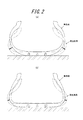
- (A) is a figure which shows the behavior before and behind the load load of the conventional pneumatic tire
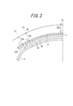
- (b) is a figure which shows the behavior before and after the load load of the pneumatic tire of this invention. It is a figure for demonstrating the measuring method of a tread gauge.
- (A) (b) is a figure for demonstrating the tensile distortion at the time of changing the neutral axis
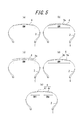
- (A)-(e) is a figure which shows the example from which the form of the belt structure of the pneumatic tire of this invention differs. It is a graph which shows rolling resistance performance and wear performance with respect to ratio BD / BW.
- FIG. 1 shows a cross section in the width direction of the pneumatic tire of the present invention (hereinafter also referred to as a tire).
- the tire 10 according to the present invention has a toroidal shape between bead portions in which a pair of bead cores 1 are embedded, and at least one layer formed by folding back around the bead core 1 from the inner side to the outer side in the tire width direction.
- Carcass 2 made of carcass ply is used as a skeleton, and at least one layer, in the illustrated example, a large number of cords extending in an inclined direction with respect to the equatorial plane CL of the carcass 2 is covered with rubber on the radially outer side of the crown portion of the carcass 2
- a belt composed of two inclined belt layers 3a and 3b and one circumferential belt layer 4 in which a large number of cords extending along the equator plane CL of the tire are covered with rubber is disposed.
- the tread 6 is arranged on the outer side in the radial direction.
- Such a tire 10 is mounted on the application rim 7 for use.
- the innermost layer 3 a with respect to the width BW of the innermost layer 3 a of the inclined belt layers 3 a and 3 b and the circumferential belt layer 4.
- the ratio BD / BW of the diameter difference BD between the center portion in the width direction (tire equatorial plane CL) and the end portion 3aE in the width direction is 0.01 or more and 0.04 or less.
- the difference in the tire radial direction of the innermost layer 3a is preferably gradually reduced from the center in the width direction (tire equatorial plane CL) to the width direction end 3aE.
- the ratio of the diameter difference TD between the tread tread surface width direction center portion (tire equator plane CL) and the tread end TE with respect to the tread ground contact width TW is TD / TW, BD / BW ⁇ TD / TW. .
- the diameter difference in the tire radial direction of the tread surface is preferably gradually reduced from the center portion in the width direction of the tread surface (tire equator surface CL) to the tread end portion TE.
- the state in which the tire 10 is mounted on the applicable rim 7 means a state in which the tire 10 is mounted on a standard rim prescribed by JATMA and an internal pressure is not applied or an extremely low internal pressure up to about 30 kPa is applied.
- the tread contact width TW means that the tire 10 is mounted on a standard rim prescribed by JATMA and pressed against a road surface (smooth road surface such as a steel road surface) with a prescribed internal pressure and a prescribed 80% load. Furthermore, it means the width of the tread where the tread tread comes into contact with the road surface.
- TRA standard and ETRTO standard are applied in a use place or a manufacturing place, it follows each standard.
- the diameter differences BD and TD are measured in parallel with the tire equatorial plane CL.
- this innermost layer is radial innermost in the belt layer which has a width
- the definition that the ratio BD / BW is 0.01 or more and 0.04 or less means that the diameter difference in the width direction of the inclined belt layer 3a is small. That is, it shows that the belt is almost flat.
- the rolling resistance is dominated by the energy loss generated in the rubber of the tread part, and suppressing shear deformation in the cross section in the width direction, which is one of the deformations, is effective in reducing rolling resistance. It is.
- the relationship that the relationship between the ratio BD / BW and the ratio TD / TW is BD / BW ⁇ TD / TW is that the belt has a flat shape, whereas the crown portion on the outer surface of the tire has a shape more than that of the belt. Shows a large drop rate and a round shape. Similar to the belt shape, in order to obtain an appropriate ground contact shape and contact pressure distribution, it is important to set the relationship with the appropriate belt shape without completely flattening in order to obtain an appropriate ground contact shape and contact pressure distribution. When the outer surface of the tire is flat rather than the belt shape, the tire center portion is lifted from the road surface, and the contact length becomes longer at the tread end portion TE than at the tire center portion.
- BD / BW ⁇ TD / TW means that the tread gauge TGh at the tread edge TE is smaller than the tread gauge TGc at the tread center.
- the tread gauge on the shoulder portion side where the wear amount is large is made thin, the wear life cannot be secured, and the wear resistance performance is lowered.
- the one where the tread gauge of the shoulder portion is thinner suppresses the increase in the contact length of the shoulder portion and the increase in the contact pressure described above. High wear resistance is obtained.
- the tread gauge of the shoulder portion is thinned, the amount of deformed rubber can be reduced, so that further reduction in rolling resistance can be achieved and the effect of reducing the weight of the tire can be obtained.
- the ratio TGh / TGc of the tread gauge TGh at the tread end portion TE to the tread gauge TGc at the center portion of the tread is 0.5 or more and 0.0. It is found that the ratio TGe / TGc of the tread gauge TGe at the widthwise end 3aE of the innermost layer 3a to the tread gauge TGc at the center of the tread is preferably 0.2 or more and 0.6 or less. did. Moreover, it is preferable that TGe ⁇ TGh. Further, the ratio TD / TW is preferably 0.05 or more, and more preferably 0.05 or more and 0.15 or less.
- the tread gauge is measured on the normal line of the carcass 2 in the cross section in the tire width direction in a state where the tire 10 is mounted on the applied rim 7, and the tread surface from the outside of the reinforcing member of the outermost circumferential belt layer 4 of the belt.
- the thickness of the tread rubber is shown.
- the tread gauge TGc at the center of the tread is measured on the tire equatorial plane CL and is the thickness of the tread rubber from the outer side of the cord c of the circumferential belt layer 4 to the tread tread.
- the tread gauge TGh at the tread end TE is measured on the normal L1 of the carcass 2 passing through the tread end TE, and is the thickness of the tread rubber from the outer side of the cord c of the circumferential belt layer 4 to the tread tread.
- the tread gauge TGe at the width direction end 3aE of the innermost layer 3a is measured on the normal L2 of the carcass 2 passing through the width direction end 3aE, and the tread from the outer side of the cord c of the circumferential belt layer 4 to the tread tread surface. The thickness of the rubber.
- the tread gauges TGc and TGh are the thickness of the tread rubber from the outer side of the cord of the inclined belt layer 3b to the tread surface, and the tread gauge TGe is inclined. This is the thickness of the tread rubber from the outside of the cord of the belt layer 3a to the tread surface. That is, the tread gauge is a distance from the outermost belt layer disposed to the tread surface.
- a tread gauge at a location closest to the tire equatorial plane CL in a tread portion having no groove is defined as TGc.
- the tread gauge indicates the thickness of the tread rubber obtained by adding the cap rubber and the base rubber.
- the lug groove depth is the same as the conventional one, the wear amount of the tread rubber is kept the same, and from the bottom of the lug groove, It is preferable to reduce the thickness of the tread rubber up to the reinforcing member of the belt layer. This is because the wear resistance performance can be greatly improved by this setting.
- a line segment drawn parallel to the tire rotation axis at the maximum width position Wcmax of the carcass 2 and the rotation of the tire to the bead toe 8 is preferably 0.6 or more and 0.9 or less, and more preferably 0.65 or more and 0.8 or less.
- the carcass line of the tire side portion has a locally bent region at a position close to the road surface, and the bending rigidity is reduced at this portion. Then, since the periphery of the bent portion, which is on the outer side in the width direction from the belt end, is greatly deformed when loaded, deformation at the tread portion is reduced. That is, the shear deformation in the cross section can be reduced in the tread. As a result of various trials of dimensions for effectively reducing deformation during loading, it was found that the ratio CSWh / CSH was 0.6 or more and 0.9 or less.
- the shortest distance SWh (hereinafter referred to as the maximum distance SWh) between the line segment drawn parallel to the tire rotation axis at the maximum width position Wmax of the tire and the line segment drawn parallel to the tire rotation axis at the bead toe 8 with respect to the tire cross-section height SH.
- the ratio SWh / SH (also referred to as a significant height) is preferably 0.5 or more and 0.8 or less, and more preferably 0.6 or more and 0.75 or less.
- the side portion is no exception. In other words, it can be said that taking the shape of the side portion following the carcass line and different from that of the conventional tire leads to efficient improvement. This means, for example, that the side rubber is thinned. If it is obvious that the side rubber can be eliminated, this dimension indicates the same position as the maximum width of the carcass line. Actually, since it is necessary to give the side rubber a predetermined thickness from the role of protecting the carcass when contacting the curbstone, the maximum width position of the side part at this time is compared with the tire cross section height, It was found to be in the ratio range. Moreover, in the tire design, the design of the vulcanization mold is also an important point, so it is necessary for the tire design to define it as the outer surface dimension.
- the ratio BW / CSW of the width BW of the innermost layer 3a to the maximum width CSW of the carcass 2 is preferably 0.8 or more and 0.94 or less, and more preferably 0.84 or more and 0.93 or less.
- the tire of the present invention has a flat belt shape.
- the ground contact shape also tends to spread in the width direction, and the configuration of the reinforcing layer corresponding to that tends to be required.
- the ground contact width between the tire and the road surface be equal to or less than the width where a plurality of reinforcing layers exist. For this reason, it has been found that the belt width in the case where the tire shape according to the present invention is adopted needs to be set wider than usual, and the width should be in accordance with the above-mentioned regulations.
- both the lower limit value regulated for uneven wear and the upper limit value regulated for rolling resistance are important.
- the ratio CSL / CSP of the path length CSL to Wcmax is preferably 0.1 or more and 0.25 or less, and more preferably 0.12 or more and 0.18 or less.
- the shortest distance CSEh (hereinafter also referred to as the folded height) between the tip 2E of the folded portion of the carcass ply of at least one layer and the bead toe 8 parallel to the tire rotation axis is referred to as the maximum width height SWh. Is also preferably large. In a tire with a belt that is almost flat, when the tire bends under load, there is little deflection of the crown portion including the belt, and bending due to deflection tends to concentrate on the side portion. Thereby, the problem on the tire appearance that a crack arises in a side surface layer part may arise.
- the carcass ply folded part is overlapped with the carcass ply body part to double the movement, and the neutral axis of bending at this part is moved to the surface layer side. ing. As a result, the distortion of the surface layer can be suppressed.
- a compressive stress acts on the inner side and a tensile stress acts on the outer side with respect to the neutral axis of bending.
- Rubber has high rigidity against compressive stress but low rigidity against tensile stress. Therefore, as shown in FIG. 4A, if the distance d from the neutral axis of the bending to the side surface is large, the tensile strain acting on the outside of the neutral axis of the bending increases, so that cracking is likely to occur in this portion. . Therefore, as shown in FIG.
- the folding height CSEh from the bead portion of the carcass ply is made higher than the maximum width height SWh, so that the carcass ply is doubled at the maximum width position Wmax of the tire where the side portion is concentrated.
- the neutral axis of the bending can be moved to the surface layer side, and the distortion of the surface layer of the side portion can be suppressed.
- the ratio CSEh / SWh is preferably larger than 1.0, more preferably 1.02 or more and 2.0 or less, and further preferably 1.02 or more and 1.24 or less.
- the ratio CSEh / SWh is preferably larger than 1.
- the reason why the lower limit of the preferable range of the ratio CSEh / SWh is 1.02 is that the turn-back height CSEh varies slightly due to manufacturing, and the turn-back height CSEh always exceeds the maximum width height SWh.
- the upper limit of the suitable range of the ratio CSEh / SWh is set to 2.0 because the effect of suppressing surface distortion is not improved even if the folding height CSEh is further increased beyond the maximum width height SWh. is there. Further, in many tires, when this ratio exceeds 2.0, the carcass ply folded tip has a positional relationship (envelope structure) exceeding the belt end. Further, if the folded portion is excessively enlarged, the deflection is also affected, and there is a possibility that the ride comfort is deteriorated due to an increase in the vertical spring. In addition, it is confirmed by the examples described later that the effect of the present invention can be sufficiently obtained when the ratio CSEh / SWh is 1.24.
- the carcass 2 can be composed of two layers of carcass plies, the carcass 2 can be sandwiched between the bead cores without rewinding the bead core 1, or the carcass 2 can have an envelope structure. it can.
- a tire having a left / right asymmetric crown shape and a right / left asymmetric belt shape / structure is also included in the present invention. Note that the average value of the left and right BDs and TDs is used as the BD and TD in the case of asymmetrical.
- FIG. 5A only one circumferential belt layer 4 having a width of 90% or more of the tread ground contact width TW may be provided as the belt.
- FIG. 5B a so-called delta structure in which one circumferential belt layer 4 having a width equal to or greater than 90% of the tread ground contact width TW and one inclined belt layer 3a is provided on the outer side in the radial direction. Can also be adopted.
- FIG. 5A shows that only one circumferential belt layer 4 having a width equal to or greater than 90% of the tread ground contact width TW and one inclined belt layer 3a is provided on the outer side in the radial direction.
- one circumferential belt layer on the radially outer side of one inclined belt layer 3a having a width of 90% or more of the tread grounding width TW. 4 may be provided.
- different cord materials in the width direction may be used for the circumferential belt layer 4 having a width of 90% or more of the tread contact width TW.
- the circumferential belt layer 4 includes a circumferential belt layer 4a formed by rubber coating a steel cord at the tread shoulder portion, and a circumferential belt layer 4b formed by rubber coating an organic fiber cord such as nylon at the tread center portion. It can also consist of.
- FIG. 5D different cord materials in the width direction may be used for the circumferential belt layer 4 having a width of 90% or more of the tread contact width TW.
- the circumferential belt layer 4 includes a circumferential belt layer 4a formed by rubber coating a steel cord at the tread shoulder portion, and a circumferential belt layer 4b formed by rubber coating an organic fiber cord such as nylon at the tread center portion. It can also consist of.
- the circumferential belt layer 4 may be composed of a left circumferential belt layer 4l and a right circumferential belt layer 4r, and the vicinity of the tire equatorial plane CL may be interrupted.
- the circumferential belt layer 4 corresponds to the “innermost layer” defined in the present invention.
- the BD in this embodiment is defined as the average value of the drop heights from the tire center side end of 4l and 4r to the end in the width direction.
- Example 1 rolling resistance performance, wear resistance performance, and weight Measurement was performed
- Example 2 Example 2
- a test for measuring a vertical spring and a durability performance test for occurrence of cracks in the side portion were performed.
- Each of the prototype tires has the same basic structure, and the carcass ply has one layer, and the inclined belt layer has cords arranged at an inclination angle of 24 ° with respect to the tire equatorial plane CL. It consists of a layer with a nylon circumferential belt layer on it. Further, the thickness from the tire inner surface to the tire outer surface at the tire maximum width position Wmax is substantially the same.
- a difference of 1.5% or more is regarded as a significant difference, and if there is a difference of 10% or more, it can be said that there is a significant difference.
- the meaning of the wear resistance test is strong. However, tires with poor partial wear performance wear early, and can be detected in this test. That is, this view can be viewed from both sides of uneven wear resistance and wear resistance.
- FIG. 6 is a graph showing the results of Table 1 with the ratio BD / BW on the horizontal axis and the rolling resistance performance and wear performance on the vertical axis. 6 and Table 1, when BD / BW is 0.01 or more and 0.04 or less and BD / BW ⁇ TD / TW, the rolling resistance performance is 96 or less, and the wear performance is 98.5. Since it is the following, it turns out that both performance is improving with respect to the conventional example tire. Further, when comparing the solid line in FIG. 6 (when the requirement of claim 1 is satisfied) with the broken line (when the requirement of claim 2 is satisfied), the rolling resistance performance and the wear performance are improved in the case of the broken line. I understand that. That is, it can be seen that rolling resistance performance and wear performance are further improved by setting TGh / TGc and TGe / TGc within appropriate ranges.
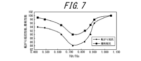
- FIG. 7 shows the ratio TGh / TGc on the horizontal axis, the rolling resistance performance and wear performance on the vertical axis, and the results of Table 1 as a graph.
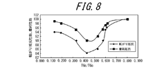
- FIG. 8 shows the ratio TGe / TGc on the horizontal axis and the rolling resistance performance on the vertical axis.
- Table 1 shows the results of Table 1 as a graph. 7 and Table 1, when TGh / TGc is 0.5 or more and 0.9 or less, the rolling resistance performance is 95 or less and the wear performance is 98.5 or less. It can be seen that both performances are improved. Furthermore, when TGh / TGc is 0.6 or more and 0.88 or less, the rolling resistance performance is 91 or less, and the wear performance is 96 or less.
- both performances are further improved.
- Table 1 when TGe / TGc is 0.2 or more and 0.6 or less, the rolling resistance performance is 95 or less and the wear performance is 98.5 or less. It can be seen that both performances are improved. Further, when TGe / TGc is 0.3 or more and 0.58 or less, the rolling resistance performance is 91 or less, and the wear performance is 96 or less, so that both performances are further improved.
- the tire weight can be reduced when BD / BW ⁇ TD / TW.
- each of the inventive tires having the specified tread gauge distribution (BD / BW ⁇ TD / TW) of the present invention has a reduced tire weight compared to the conventional tires, and has both rolling resistance performance and wear performance.
- FIG. 9 is a graph showing the results of Table 1 with the ratio CSWh / CSH on the horizontal axis and the rolling resistance performance and wear performance on the vertical axis. From FIG. 9 and Table 1 (Invention Examples 7, 11 to 15), when CSwh / CSH is 0.6 or more and 0.9 or less, the rolling resistance performance is 86 or less, and the wear performance is 90 or less. It turns out that both performance is improving with respect to the conventional example tire. Furthermore, when CSWH / CSH is 0.7 or more and 0.8 or less, the rolling resistance performance is 80 or less, and the wear performance is 85 or less, so that both performances are further improved.
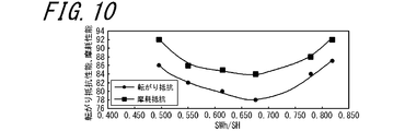
- FIG. 10 is a graph showing the results in Table 1 with the ratio SWh / SH on the horizontal axis and the rolling resistance performance and wear performance on the vertical axis. From FIG. 10 and Table 1 (Invention Examples 7, 11 to 15), when SWh / SH is 0.5 or more and 0.8 or less, the rolling resistance performance is 86 or less, and the wear performance is 90 or less. It turns out that both performance is improving with respect to the conventional example tire. Furthermore, when CSWH / CSH is 0.6 or more and 0.75 or less, the rolling resistance performance is 81 or less, and the wear performance is 87 or less. Therefore, it can be seen that both performances are further improved.
- FIG. 11 is a graph showing the results in Table 1 with the ratio BW / CSW on the horizontal axis and the rolling resistance performance and wear performance on the vertical axis. From FIG. 11 and Table 1 (Invention Examples 13, 16 to 20), when BW / CSW is 0.8 or more and 0.94 or less, the rolling resistance performance is 77 or less, and the wear performance is 81 or less. It turns out that both performance is improving with respect to the conventional example tire. Furthermore, when BW / CSW is 0.84 or more and 0.93 or less, the rolling resistance performance is 73 or less, and the wear performance is 79 or less. Therefore, it can be seen that both performances are further improved.
- FIG. 12 is a graph showing the results in Table 1 with the ratio CSL / CSP on the horizontal axis and the rolling resistance performance and wear performance on the vertical axis. From FIG. 12 and Table 1 (Invention Examples 17, 21 to 25), when CSL / CSP is 0.1 or more and 0.25 or less, the rolling resistance performance is 78 or less, and the wear performance is 82 or less. It turns out that both performance is improving with respect to the conventional example tire. Furthermore, when CSL / CSP is 0.12 or more and 0.24 or less, the rolling resistance performance is 75 or less, and the wear performance is 81 or less, so that both performances are further improved.
Landscapes
- Engineering & Computer Science (AREA)
- Mechanical Engineering (AREA)
- Tires In General (AREA)
Abstract
L'invention porte sur un pneu, qui comprend au moins une couche de ceinture (3, 4) et une bande de roulement (6) qui sont disposées sur le côté externe de façon radiale par rapport à la section de couronne d'une couche de carcasse (2) qui sert d'ossature et qui chevauche de façon toroïdale une paire de sections de talon. Dans une section transversale du pneu, prise dans la direction de la largeur du pneu quand le pneu est monté sur une jante applicable (7), si le rapport (BD/BW) de la différence (BD) entre le diamètre de la couche située le plus à l'intérieur (3a) de la couche de ceinture (3, 4), mesuré au centre de la couche située le plus à l'intérieur (3a) dans la direction de la largeur, et le diamètre de la couche située le plus à l'intérieur (3a), mesuré aux extrémités de celle-ci dans la direction de la largeur, à la largeur (BW) de la couche située le plus à l'intérieur (3a) de la couche de ceinture (3, 4), est dans la plage de 0,01 à 0,04 inclus, et, également, si le rapport de la différence (TD) entre le diamètre de la surface de la bande de roulement, mesuré au centre de celle-ci dans la direction de la largeur, et le diamètre de la surface de la bande de roulement aux extrémités de la bande de roulement (6), à la largeur (TW) de la surface de contact avec le sol de la bande de roulement, est TD/TW, la relation BD/BW < TD/TW est satisfaite.
Priority Applications (4)
| Application Number | Priority Date | Filing Date | Title |
|---|---|---|---|
| EP12803157.2A EP2722198B1 (fr) | 2011-06-20 | 2012-05-17 | Pneu |
| US14/127,279 US20140138002A1 (en) | 2011-06-20 | 2012-05-17 | Pneumatic tire |
| CN201280030455.7A CN103619612B (zh) | 2011-06-20 | 2012-05-17 | 充气轮胎 |
| US16/390,245 US11458769B2 (en) | 2011-06-20 | 2019-04-22 | Pneumatic tire |
Applications Claiming Priority (2)
| Application Number | Priority Date | Filing Date | Title |
|---|---|---|---|
| JP2011136674A JP6050568B2 (ja) | 2011-06-20 | 2011-06-20 | 空気入りタイヤ |
| JP2011-136674 | 2011-06-20 |
Related Child Applications (2)
| Application Number | Title | Priority Date | Filing Date |
|---|---|---|---|
| US14/127,279 A-371-Of-International US20140138002A1 (en) | 2011-06-20 | 2012-05-17 | Pneumatic tire |
| US16/390,245 Continuation US11458769B2 (en) | 2011-06-20 | 2019-04-22 | Pneumatic tire |
Publications (1)
| Publication Number | Publication Date |
|---|---|
| WO2012176372A1 true WO2012176372A1 (fr) | 2012-12-27 |
Family
ID=47422237
Family Applications (1)
| Application Number | Title | Priority Date | Filing Date |
|---|---|---|---|
| PCT/JP2012/003236 Ceased WO2012176372A1 (fr) | 2011-06-20 | 2012-05-17 | Pneu |
Country Status (5)
| Country | Link |
|---|---|
| US (2) | US20140138002A1 (fr) |
| EP (1) | EP2722198B1 (fr) |
| JP (1) | JP6050568B2 (fr) |
| CN (1) | CN103619612B (fr) |
| WO (1) | WO2012176372A1 (fr) |
Cited By (2)
| Publication number | Priority date | Publication date | Assignee | Title |
|---|---|---|---|---|
| JP5494894B1 (ja) * | 2013-08-12 | 2014-05-21 | 横浜ゴム株式会社 | 乗用車用空気入りタイヤ |
| JP2015036261A (ja) * | 2013-08-12 | 2015-02-23 | 横浜ゴム株式会社 | 乗用車用空気入りタイヤ |
Families Citing this family (23)
| Publication number | Priority date | Publication date | Assignee | Title |
|---|---|---|---|---|
| JP6241125B2 (ja) * | 2013-08-12 | 2017-12-06 | 横浜ゴム株式会社 | 乗用車用空気入りタイヤ |
| JP6236978B2 (ja) * | 2013-08-12 | 2017-11-29 | 横浜ゴム株式会社 | 乗用車用空気入りタイヤ |
| JP6052227B2 (ja) * | 2014-05-12 | 2016-12-27 | 横浜ゴム株式会社 | 更生タイヤ |
| JP5928525B2 (ja) * | 2014-05-20 | 2016-06-01 | 横浜ゴム株式会社 | 空気入りタイヤ |
| FR3026989B1 (fr) * | 2014-10-08 | 2016-11-04 | Michelin & Cie | Sommet de pneumatique pour avion |
| JP6489917B2 (ja) * | 2015-04-21 | 2019-03-27 | 株式会社ブリヂストン | 空気入りタイヤ |
| JP6785104B2 (ja) * | 2015-10-02 | 2020-11-18 | 株式会社ブリヂストン | 建設車両用タイヤ |
| WO2017057705A1 (fr) * | 2015-10-02 | 2017-04-06 | 株式会社ブリヂストン | Pneu pour véhicules de construction |
| CN105437870A (zh) * | 2015-12-22 | 2016-03-30 | 三角轮胎股份有限公司 | 充气工业子午线轮胎 |
| JP6720539B2 (ja) * | 2016-01-13 | 2020-07-08 | 住友ゴム工業株式会社 | 空気入りタイヤ |
| JP7077556B2 (ja) * | 2017-09-25 | 2022-05-31 | 横浜ゴム株式会社 | 乗用車用空気入りタイヤ |
| JP6988540B2 (ja) * | 2018-02-14 | 2022-01-05 | 横浜ゴム株式会社 | 空気入りタイヤ |
| JP7091715B2 (ja) * | 2018-03-02 | 2022-06-28 | 住友ゴム工業株式会社 | タイヤ |
| JP7012591B2 (ja) * | 2018-04-23 | 2022-01-28 | 株式会社ブリヂストン | タイヤ |
| JP6835110B2 (ja) * | 2019-01-31 | 2021-02-24 | 横浜ゴム株式会社 | 空気入りタイヤ |
| JP7238599B2 (ja) * | 2019-05-24 | 2023-03-14 | 横浜ゴム株式会社 | 空気入りタイヤ |
| JP2021059312A (ja) * | 2019-10-09 | 2021-04-15 | 株式会社ブリヂストン | タイヤ・ホイール組立体 |
| JP7463712B2 (ja) * | 2019-12-18 | 2024-04-09 | 住友ゴム工業株式会社 | 重荷重用チューブレスタイヤ及び製造方法 |
| JP7568397B2 (ja) * | 2019-12-19 | 2024-10-16 | 株式会社ブリヂストン | タイヤ・ホイール組立体 |
| JP7506301B2 (ja) * | 2020-04-03 | 2024-06-26 | 横浜ゴム株式会社 | 空気入りタイヤ |
| JP7529972B2 (ja) * | 2020-04-03 | 2024-08-07 | 横浜ゴム株式会社 | 空気入りタイヤ |
| JP7755475B2 (ja) * | 2021-12-10 | 2025-10-16 | 株式会社ブリヂストン | 乗用車用空気入りラジアルタイヤ |
| JP7733559B2 (ja) * | 2021-12-10 | 2025-09-03 | 株式会社ブリヂストン | 乗用車用空気入りラジアルタイヤ |
Citations (6)
| Publication number | Priority date | Publication date | Assignee | Title |
|---|---|---|---|---|
| JPS5787704A (en) * | 1980-11-20 | 1982-06-01 | Bridgestone Corp | Pneumatic tire with reduced rolling resistance |
| JP2006327502A (ja) | 2005-05-27 | 2006-12-07 | Bridgestone Corp | 空気入りタイヤ |
| JP2009166819A (ja) | 2007-12-17 | 2009-07-30 | Bridgestone Corp | 空気入りタイヤ |
| JP2009279948A (ja) * | 2008-05-19 | 2009-12-03 | Bridgestone Corp | 空気入りタイヤ |
| JP2010167849A (ja) * | 2009-01-21 | 2010-08-05 | Bridgestone Corp | ランフラットタイヤ |
| WO2011043041A1 (fr) * | 2009-10-08 | 2011-04-14 | 株式会社ブリヂストン | Bandage pneumatique |
Family Cites Families (8)
| Publication number | Priority date | Publication date | Assignee | Title |
|---|---|---|---|---|
| US3570575A (en) * | 1968-07-24 | 1971-03-16 | Gneral Tire & Rubber Co The | Radial ply pneumatic tire with high angle breaker assembly |
| JP2563346B2 (ja) * | 1987-06-17 | 1996-12-11 | 住友ゴム工業株式会社 | 乗用車用ラジアルタイヤ |
| US5115853A (en) * | 1989-03-08 | 1992-05-26 | The Goodyear Tire & Rubber Company | Pneumatic tire with belt overlay structure reinforced with low denier nylon cords |
| JPH05201202A (ja) | 1992-01-29 | 1993-08-10 | Bridgestone Corp | 空気入りタイヤ |
| US6073668A (en) * | 1997-04-16 | 2000-06-13 | Sumitomo Rubber Industries, Inc. | Vehicle tire including tread portion having profile |
| US6321809B1 (en) * | 1999-12-22 | 2001-11-27 | The Goodyear Tire & Rubber Company | Unique radial passenger tire construction for RAT/RLF |
| JP4170821B2 (ja) * | 2003-05-30 | 2008-10-22 | 住友ゴム工業株式会社 | 空気入りラジアルタイヤ |
| JP2009078425A (ja) | 2007-09-26 | 2009-04-16 | Toppan Printing Co Ltd | 印刷用版およびその製造方法および印刷物の製造方法 |
-
2011
- 2011-06-20 JP JP2011136674A patent/JP6050568B2/ja active Active
-
2012
- 2012-05-17 CN CN201280030455.7A patent/CN103619612B/zh not_active Expired - Fee Related
- 2012-05-17 US US14/127,279 patent/US20140138002A1/en not_active Abandoned
- 2012-05-17 WO PCT/JP2012/003236 patent/WO2012176372A1/fr not_active Ceased
- 2012-05-17 EP EP12803157.2A patent/EP2722198B1/fr not_active Not-in-force
-
2019
- 2019-04-22 US US16/390,245 patent/US11458769B2/en active Active
Patent Citations (6)
| Publication number | Priority date | Publication date | Assignee | Title |
|---|---|---|---|---|
| JPS5787704A (en) * | 1980-11-20 | 1982-06-01 | Bridgestone Corp | Pneumatic tire with reduced rolling resistance |
| JP2006327502A (ja) | 2005-05-27 | 2006-12-07 | Bridgestone Corp | 空気入りタイヤ |
| JP2009166819A (ja) | 2007-12-17 | 2009-07-30 | Bridgestone Corp | 空気入りタイヤ |
| JP2009279948A (ja) * | 2008-05-19 | 2009-12-03 | Bridgestone Corp | 空気入りタイヤ |
| JP2010167849A (ja) * | 2009-01-21 | 2010-08-05 | Bridgestone Corp | ランフラットタイヤ |
| WO2011043041A1 (fr) * | 2009-10-08 | 2011-04-14 | 株式会社ブリヂストン | Bandage pneumatique |
Non-Patent Citations (1)
| Title |
|---|
| See also references of EP2722198A4 |
Cited By (6)
| Publication number | Priority date | Publication date | Assignee | Title |
|---|---|---|---|---|
| JP5494894B1 (ja) * | 2013-08-12 | 2014-05-21 | 横浜ゴム株式会社 | 乗用車用空気入りタイヤ |
| WO2015022720A1 (fr) * | 2013-08-12 | 2015-02-19 | 横浜ゴム株式会社 | Bandage pneumatique d'automobile |
| JP2015036261A (ja) * | 2013-08-12 | 2015-02-23 | 横浜ゴム株式会社 | 乗用車用空気入りタイヤ |
| CN105408130A (zh) * | 2013-08-12 | 2016-03-16 | 横滨橡胶株式会社 | 乘用车用充气轮胎 |
| CN105408130B (zh) * | 2013-08-12 | 2017-10-20 | 横滨橡胶株式会社 | 乘用车用充气轮胎 |
| US11453250B2 (en) | 2013-08-12 | 2022-09-27 | The Yokohama Rubber Co., Ltd. | Pneumatic tire for passenger vehicle |
Also Published As
| Publication number | Publication date |
|---|---|
| CN103619612B (zh) | 2016-05-11 |
| JP6050568B2 (ja) | 2016-12-21 |
| US20190248183A1 (en) | 2019-08-15 |
| US20140138002A1 (en) | 2014-05-22 |
| JP2013001333A (ja) | 2013-01-07 |
| EP2722198B1 (fr) | 2018-07-04 |
| CN103619612A (zh) | 2014-03-05 |
| EP2722198A4 (fr) | 2015-07-01 |
| EP2722198A1 (fr) | 2014-04-23 |
| US11458769B2 (en) | 2022-10-04 |
Similar Documents
| Publication | Publication Date | Title |
|---|---|---|
| JP6050568B2 (ja) | 空気入りタイヤ | |
| JP5735743B2 (ja) | 空気入りタイヤ | |
| JP4973810B1 (ja) | 空気入りタイヤ | |
| JP5366629B2 (ja) | 空気入りタイヤ | |
| JP5683977B2 (ja) | 農業用タイヤ | |
| KR102034751B1 (ko) | 공기 타이어 | |
| JP6317165B2 (ja) | ランフラットタイヤ | |
| JP2009279948A (ja) | 空気入りタイヤ | |
| WO2011043041A1 (fr) | Bandage pneumatique | |
| JP2020011548A (ja) | 重荷重用空気入りタイヤ | |
| JP5265394B2 (ja) | ランフラットタイヤ | |
| WO2014199756A1 (fr) | Pneu à roulement à plat | |
| JP5557508B2 (ja) | 空気入りタイヤ | |
| JP2013079018A (ja) | 空気入りタイヤ | |
| JP2011079469A (ja) | 空気入りタイヤ | |
| JP5497401B2 (ja) | 空気入りタイヤ | |
| WO2016024390A1 (fr) | Bandage pneumatique | |
| JP5030545B2 (ja) | 空気入りラジアルタイヤ | |
| CN121358615A (zh) | 充气轮胎 | |
| JP2010254248A (ja) | 空気入りタイヤ | |
| JP2014237392A (ja) | 空気入りタイヤ |
Legal Events
| Date | Code | Title | Description |
|---|---|---|---|
| WWE | Wipo information: entry into national phase |
Ref document number: 201280030455.7 Country of ref document: CN |
|
| 121 | Ep: the epo has been informed by wipo that ep was designated in this application |
Ref document number: 12803157 Country of ref document: EP Kind code of ref document: A1 |
|
| WWE | Wipo information: entry into national phase |
Ref document number: 14127279 Country of ref document: US |
|
| NENP | Non-entry into the national phase |
Ref country code: DE |