WO2012176523A1 - 画像提供装置、画像処理方法、画像処理プログラム及び記録媒体 - Google Patents
画像提供装置、画像処理方法、画像処理プログラム及び記録媒体 Download PDFInfo
- Publication number
- WO2012176523A1 WO2012176523A1 PCT/JP2012/058826 JP2012058826W WO2012176523A1 WO 2012176523 A1 WO2012176523 A1 WO 2012176523A1 JP 2012058826 W JP2012058826 W JP 2012058826W WO 2012176523 A1 WO2012176523 A1 WO 2012176523A1
- Authority
- WO
- WIPO (PCT)
- Prior art keywords
- image
- mosaic
- system control
- control unit
- area
- Prior art date
- Legal status (The legal status is an assumption and is not a legal conclusion. Google has not performed a legal analysis and makes no representation as to the accuracy of the status listed.)
- Ceased
Links
Images






Classifications
-
- H—ELECTRICITY
- H04—ELECTRIC COMMUNICATION TECHNIQUE
- H04N—PICTORIAL COMMUNICATION, e.g. TELEVISION
- H04N5/00—Details of television systems
- H04N5/222—Studio circuitry; Studio devices; Studio equipment
- H04N5/262—Studio circuits, e.g. for mixing, switching-over, change of character of image, other special effects ; Cameras specially adapted for the electronic generation of special effects
- H04N5/265—Mixing
-
- G—PHYSICS
- G06—COMPUTING OR CALCULATING; COUNTING
- G06T—IMAGE DATA PROCESSING OR GENERATION, IN GENERAL
- G06T3/00—Geometric image transformations in the plane of the image
- G06T3/40—Scaling of whole images or parts thereof, e.g. expanding or contracting
- G06T3/4038—Image mosaicing, e.g. composing plane images from plane sub-images
Definitions
- the present invention relates to a technical field of an image providing apparatus and an image processing method for presenting a mosaic image formed by combining images acquired from a terminal device.
- a plurality of images are arranged in tiles to form a mosaic image (for example, , Mosaic art, photo mosaic, etc.) are known.
- a mosaic image for example, , Mosaic art, photo mosaic, etc.
- an image hereinafter referred to as an “original image” that is a source of a pattern of a mosaic image is divided into a plurality of regions. Then, each material image is assigned to an area close to, for example, a color tone or a pattern. Thereby, a mosaic image expressing the pattern of the original image is generated.
- a server device acquires an image provided as a material image from a user from a terminal device via a network, and displays a mosaic image generated using the acquired image on the terminal device.
- a problem is how to generate a mosaic image with high visibility of the pattern of the original image.
- Patent Document 1 discloses a technique for providing a mosaic image with high visibility. Specifically, the block selected by the user when the mosaic image providing apparatus determines a block that is a placement target of the material image posted by the user from among a plurality of blocks obtained by dividing the target image that is the source of the mosaic image. Is determined as the arrangement target, or the arrangement target is automatically determined without being limited to the block image.
- the mosaic image providing apparatus performs color correction on the material image so that the average density value of the basic color of the material image becomes the average density value of the basic color of the arrangement target block.
- the mosaic image in which the material image is arranged only for some blocks is displayed on the terminal device. The That is, an unfinished mosaic image is displayed.
- the visibility of the pattern of the original image may not increase.
- the ratio of the area of one block to the original image increases. Therefore, the resolution of the mosaic image is lowered, and the mosaic image becomes a coarse image.
- the area of one block is reduced, the total number of blocks necessary for completing the mosaic image increases, and many material images are required until the mosaic image is completed.
- the present invention has been made in view of the above points, and is an image providing apparatus capable of providing a mosaic image with high visibility of the pattern of the original image while suppressing the number of regions necessary for completing the mosaic image.
- An object of the present invention is to provide an image processing method, an image processing program, and a recording medium.
- the invention according to claim 1 is an image providing apparatus that provides a mosaic image of an original image divided into a plurality of regions, and that detects an edge of the image from the plurality of regions.
- a specifying unit for specifying a region to be included; a dividing unit for further dividing the specified region into a plurality of regions; an acquiring unit for acquiring an image designated by a user; and dividing by the dividing unit among the plurality of regions.
- a determination unit that determines a region to which the acquired image is allocated from among a region that is not divided and a region that is created by the division by the division unit, and the allocation determined by the determination unit, Presenting means for presenting a mosaic image in which the acquired image is arranged.
- the region including the edge that contributes to the improvement in the visibility of the original image among the plurality of regions is divided into smaller regions, so that the number of regions necessary for completing the mosaic image is reduced and the original image is reduced. It is possible to provide a mosaic image with high visibility of the pattern.
- the specifying unit calculates an edge degree indicating a degree of an edge included in the image of the region, and the edge degree is preset.
- the region that is equal to or greater than the specified value is specified as a region including an edge.
- an area including an edge can be determined by a preset value.
- the dividing unit divides the specified area so that the number of divisions increases as the calculated edge degree increases. It is characterized by that.
- the present invention since the number of divisions changes depending on the degree of the influence on the visibility of the original image even in the region including the edge, the visibility of the design of the original image is reduced while suppressing the number of divisions of the original image. A higher mosaic image can be provided.
- the invention according to claim 4 is an image processing method in an image providing apparatus that provides a mosaic image of an original image divided into a plurality of regions, and specifies a region including an edge of the image from the plurality of regions.
- An identifying step for dividing the identified region into a plurality of regions, an obtaining step for obtaining an image specified by the user, and a region that is not divided in the dividing step among the plurality of regions.
- a determination step for determining a region to which the acquired image is assigned from among the regions created by the division in the division step, and the acquired image based on the assignment determined in the determination step.
- a presenting step of presenting a mosaic image in which is arranged.
- a computer included in an image providing apparatus that provides a mosaic image of an original image divided into a plurality of areas is specified for specifying an area including an image edge from the plurality of areas.
- Means for further dividing the identified area into a plurality of areas an acquisition means for acquiring an image designated by a user, an area not divided by the dividing means among the plurality of areas, and the dividing means
- a determination unit for determining a region to which the acquired image is allocated from among the regions created by the division according to (2), and the acquired image is arranged based on the allocation determined by the determination unit It is characterized by functioning as a presentation means for presenting a mosaic image.
- a computer included in an image providing apparatus that provides a mosaic image of an original image divided into a plurality of regions is used to specify a region that includes an edge of the image from the plurality of regions.
- a determination unit for determining a region to which the acquired image is allocated from among the regions created by the division according to (2), and the acquired image is arranged based on the allocation determined by the determination unit
- An image processing program that functions as presentation means for presenting a mosaic image is recorded in a computer-readable manner.
- an area including an edge that contributes to improving the visibility of an original image among a plurality of areas is divided into smaller areas, so that the number of areas necessary for completing a mosaic image is reduced and the original image is reduced. It is possible to provide a mosaic image with high visibility of the pattern.
- FIG. 1 It is a figure which shows an example of schematic structure of the mosaic image provision system S which concerns on one Embodiment.
- (A) is a figure which shows the example of the original image 100 divided
- (b) is a figure which shows the example of the original image 100 by which the basic area containing an edge was divided
- (A) is a figure which shows the example of a display of the completed mosaic image 300a when it is assumed that a contribution image is allocated only with respect to a basic area
- (b) is a figure which the contribution image was allocated to the child area
- FIG. 1 It is a block diagram which shows an example of schematic structure of the mosaic image provision server 1 which concerns on one Embodiment.
- A is a figure which shows an example of the content registered into member information DB12a which concerns on one Embodiment
- (b) is a figure which shows an example of the content registered into original image DB12b
- (c) Is a diagram showing an example of content set in basic area information
- (d) is a diagram showing an example of content registered in post image DB 12c
- (e) is set in post image information.
- F is a figure which shows an example of the content registered into mosaic image DB12d
- (g) is a figure which shows an example of the content set to allocation image information. is there.
- FIG.2 It is a figure which shows an example of the edge degree of each basic area
- (A) is a figure which shows an example of the content set to a division
- (b) is a figure which shows an example of the content set to division
- It is a flowchart which shows the process example in the original image registration process of the system control part 14 of the mosaic image provision server 1 which concerns on one Embodiment.
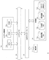
- FIG. 1 is a diagram illustrating an example of a schematic configuration of a mosaic image providing system S according to the present embodiment.
- the mosaic image providing system S includes a mosaic image providing server 1 and a plurality of user terminals 2.
- the mosaic image providing server 1 and each user terminal 2 can transmit / receive data to / from each other using, for example, TCP / IP as a communication protocol via the network NW.
- the network NW is constructed by, for example, the Internet, a dedicated communication line (for example, a CATV (Community Antenna Television) line), a mobile communication network (including a base station), a gateway, and the like.
- the mosaic image providing server 1 (an example of an image providing apparatus in the present invention) transmits a Web page on which a mosaic image that can be obtained by arranging (combining) a plurality of images serving as materials in a tile shape is displayed to the user terminal 2. Web server.
- the mosaic image providing server 1 acquires images from each user terminal 2 via the network NW in order to collect images that are materials.
- the image acquired from the user terminal 2 is an image posted by the user (hereinafter referred to as “posted image”).
- the user terminal 2 is a terminal device of a user who uses the mosaic image providing system S.
- the user terminal 2 accesses the mosaic image providing server 1 based on an operation from the user. Thereby, the user terminal 2 receives and displays the Web page from the mosaic image providing server 1.
- the user posts an image that is a material of a mosaic image or displays a mosaic image through a Web page displayed on the screen of the user terminal 2.
- Software such as a browser and an e-mail client is incorporated in the user terminal 2.
- the mosaic image providing system S having such a configuration, for example, an image that is a source of the pattern of the mosaic image is prepared in advance. This image is the original image.
- the mosaic image providing server 1 arranges the posted images so that the pattern represented by the mosaic image is close to the pattern represented by the original image.
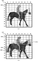
- FIG. 2A and FIG. 2B are diagrams showing an example of the original image and an example of dividing the original image.
- An image 100 shown in FIGS. 2A and 2B is an image representing a pattern of a walking horse and a jockey riding on the horse.
- the color of the horse is dark brown.
- the color of the trousers of the jockey is yellow and the color of the jacket of the jockey is light blue.
- the background color is white. Note that each color is not filled with a uniform color, but changes in color to some extent depending on the location.
- the original image is divided into a plurality of areas (hereinafter referred to as “divided areas”).
- a posted image acquired from the user terminal 2 is assigned to each divided area.
- the mosaic image providing server 1 divides the original image into a preset number of divided regions.
- a divided area created when the original image is first divided is called a “basic area”.
- the image 100 is divided into 99 divided areas 200, which are 9 basic areas and 11 vertical areas.
- the number of divided areas is referred to as “divided number”.
- the total number of basic areas is referred to as “basic division number”.
- FIG. 3A is a diagram illustrating a display example of the completed mosaic image 300a when it is assumed that the posted image is assigned only to the basic region.
- a completed mosaic image is a mosaic image in which posted images are assigned to all divided regions.
- the ratio of the display area of each divided region 200 to the display area of the original image is relatively large. Therefore, if a mosaic image is generated in this state, a mosaic image having a relatively low resolution is generated as shown in FIG. Therefore, the visibility of the pattern of the original image is not high.
- the mosaic image providing server 1 further divides the basic region including the edge of the image into a plurality of divided regions (hereinafter referred to as “child regions”) so that the visibility of the pattern of the original image is increased.
- An edge refers to a portion where the brightness, hue, saturation, etc. of an image changes abruptly (sharply).
- the basic region including the edge may be, for example, a contour portion, a feature portion, a complicated pattern portion, or the like of the pattern of the original image.
- the mosaic image providing server 1 calculates the edge degree of each basic area as an index indicating the degree of the edge in order to identify the basic area including the edge. The higher the degree of change in the brightness or the like of the image included in the basic area, that is, the stronger the edge, the higher the edge degree of the basic area. Further, the greater the amount of edges included in the divided area, the higher the edge degree of the basic area. Then, the mosaic image providing server 1 determines a basic region whose edge degree is equal to or greater than a preset threshold as a basic region including an edge.
- the mosaic image providing server 1 increases the number of divisions as the basic region has a higher edge degree. That is, the mosaic image providing server 1 divides into more child areas. Therefore, the basic region having a higher edge degree is divided into smaller child regions. The number of divisions at this time is referred to as “number of child divisions”.
- a divided area 200 including an edge has a total of four divided areas 210, two horizontal and two vertical, three horizontal and three vertical depending on the degree of edge. It is divided into any of the nine divided regions 220 or any child region out of a total of 16 divided regions 230 of 4 horizontal and 4 vertical.
- the mosaic image providing server 1 assigns a posted image to a basic area for a basic area that is not divided into child areas.
- the mosaic image providing server 1 assigns a posted image to a child area created (generated) by dividing the basic area divided into child areas.
- FIG. 3B is a diagram showing a display example of the completed mosaic image 300b.
- FIG. 3B is a mosaic image generated by assigning a posted image to each divided region shown in FIG.
- the display area per one divided region in the edge portion is smaller than the display area per one divided region in the portion having no edge. Therefore, the resolution of the edge portion is increased, and the visibility of the edge can be improved.
- the visibility of the pattern of an original image can be improved by improving the visibility of an edge.
- the display area per division area becomes smaller as the edge degree is higher, the visibility of the pattern of the original image can be further improved.
- the number of divided areas 200 divided into four divided areas 210 is seventeen.
- the number of divided areas 200 divided into nine divided areas 220 is 24.
- the number of divided areas 200 divided into 16 divided areas 230 is four.
- the total number of divided areas is 402.
- the total number of divided regions is 496.
- the mosaic image providing server 1 does not divide the basic area having a small influence on the visibility of the design of the original image into the child areas, or reduces the number of child divisions even if divided. Thereby, by suppressing the total number of divided areas, it is possible to reduce the number of posted images necessary for completing the mosaic image and improve the visibility of the pattern of the original image.
- FIG. 4 is a block diagram illustrating an example of a schematic configuration of the mosaic image providing server 1 according to the present embodiment.
- the mosaic image providing server 1 includes a communication unit 11, a storage unit 12, an input / output interface 13, and a system control unit 14.
- the system control unit 14 and the input / output interface 13 are connected via a system bus 15.
- the communication unit 11 is connected to the network NW and controls the communication state with the user terminal 2 and the like.
- the storage unit 12 is composed of, for example, a hard disk drive.
- a member information DB (database) 12a an original image DB 12b, a posted image DB 12c, a mosaic image DB 12d, and the like are constructed.
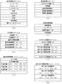
- FIG. 5A is a diagram showing an example of contents registered in the member information DB 12a according to the present embodiment.
- member information related to users who are registered as members in the mosaic image providing system S is registered. Specifically, the user ID, password, nickname, name, date of birth, gender, address, telephone number, e-mail address, etc., which are user identification information, are registered in association with each user in the member information DB 12a.
- the user ID, password, nickname, name, date of birth, gender, address, telephone number, e-mail address, etc. which are user identification information, are registered in association with each user in the member information DB 12a.
- FIG. 5B is a diagram illustrating an example of contents registered in the original image DB 12b according to the present embodiment.
- the original image and information related to the original image are registered.
- an original image ID, original image data, basic division number information, and a plurality of basic area information, which are identification information of the original image are registered in association with each original image.
- the original image ID is identification information of the original image.
- the original image data is image data of the original image. Examples of the format of image data used in the mosaic image providing system S include JPEG (Joint Photographic Experts Group), TIFF (Tagged-Image File Format), PNG (Portable Network Graphics), and the like.
- the basic division number information is information indicating the basic division number.
- the basic division number information includes a basic division number, a basic horizontal division number, and a basic vertical division number.
- the basic horizontal division number is the horizontal division number. That is, the basic horizontal division number is the number of basic regions arranged in the horizontal direction of the original image.
- the basic vertical division number is the vertical division number. That is, the basic vertical division number is the number of basic regions arranged in the vertical direction of the original image.
- the basic division number is obtained by multiplying the basic horizontal division number and the basic vertical division number.
- the basic area information is information related to the basic area.
- Basic area information is registered for the number of basic divisions. Each basic area information is registered in association with the index of the corresponding basic area.
- Each basic area is assigned an index in the form of (X1, Y1).
- X1 indicates the position of the basic region in the horizontal direction.
- Y1 indicates the position of the basic region in the vertical direction.
- the index of the basic area located at the upper left corner of the original image is (0, 0).
- the basic area (X1, Y1) is a basic area located Y1 + 1 from the top among the basic areas located X1 + 1 from the leftmost.
- dividing the original image into a plurality of areas means dividing an area corresponding to the entire original image into a plurality of areas, and in which area each pixel in the original image is included ( Alternatively, it is possible to specify which pixels each region includes).
- the system control unit 14 can specify a region including each pixel by acquiring the number of vertical and horizontal pixels, the number of horizontal divisions, and the number of vertical divisions of the original image. Therefore, dividing the original image into a plurality of regions does not necessarily mean dividing the image data of the original image into image data for each region. Therefore, the system control unit 14 may or may not register the image data for each area in the original image DB 12b.
- FIG. 5C is a diagram showing an example of contents set in the basic area information. As shown in FIG. 5C, the basic area information is set with an edge degree, child division number information, and one or more representative color values.
- the edge degree is used to determine whether or not to divide the basic region and to determine the number of child divisions when dividing.
- the edge degree is calculated by the system control unit 14.
- the system control unit 14 calculates the pixel edge degree of each pixel included in the basic region.
- the pixel edge degree indicates the strength of the edge of the pixel itself.
- the system control unit 14 calculates the difference between the value of the target pixel (the pixel for which the pixel edge degree is calculated) and the value of each pixel adjacent to the target pixel.
- the pixel value exists for each basic color (primary color) of R (red), G (green), and B (blue), for example.
- Each pixel value of R, G, and B takes any value from 0 to 255, for example.
- the system control unit 14 performs this calculation for each basic color.
- the pixels adjacent to the target pixel are eight pixels located in the up / down / left / right and diagonal directions of the target pixel. Then, the system control unit 14 adds the differences calculated for each basic color, and further adds the differences for 8 pixels to calculate the pixel edge degree.
- equations the following equation 1 is obtained.
- Equation 1 x is the X coordinate of the pixel of interest based on the pixel in the upper left corner of the region of interest (the basic region for which the edge degree is calculated), and y is in the upper left corner of the region of interest. This is the Y coordinate of the target pixel based on the pixel.
- R (x, y), G (x, y), and B (x, y) are the R pixel value, G pixel value, and B pixel value of the pixel at coordinates (x, y).
- EP (x, y) is the pixel edge degree of the pixel at the coordinates (x, y).
- the pixel value may be expressed in, for example, CMYK, Lab color space, or the like.
- the system control unit 14 calculates the square of the difference calculated for each basic color instead of taking the absolute value of the difference calculated for each basic color and adding the absolute values, and calculates the calculation result. You can add them together.
- the system control unit 14 adds the pixel edge degrees of all the pixels in the basic area, and calculates the edge degree of the basic area. This process is expressed by the following formula 2.
- EB (X1, Y1) is the edge degree of the basic region (X1, Y1). Further, w is the number of pixels in the horizontal direction of the basic region, and l is the number of pixels in the vertical direction of the basic region.
- the edge degree calculation method is not limited to the method described here. For example, when calculating the pixel edge degree, the system control unit 14 may calculate a difference in pixel values for only four pixels located above, below, left, and right of the target pixel. In addition, the system control unit 14 does not calculate the difference between the pixel values for each basic color, but calculates the distance between the color of the pixel of interest and the color of the adjacent pixel, for example, and adds the color distances Then, the pixel edge degree may be calculated.
- FIG. 6 is a diagram showing an example of the edge degree of each basic region 200 shown in FIG. FIG. 6 shows the normalized edge degree so that the difference in edge degree of each basic region can be easily understood.
- the edge degree of the basic region including no edge is zero.
- the edge degree of the basic region including the outline of the horse and the outline of the jockey increases with the length of the outline.
- the edge degree is high in the contour portion of a horse having a large difference in brightness from the background.
- the tail part of a horse with many lines for example, basic areas (0, 6), (0, 7)
- the hand part of a jockey with a complicated pattern for example, basic areas (4, 3)
- the degree is getting higher.
- Child division number information is information indicating the number of child divisions of the basic area (X1, Y1). Specifically, the child division number information includes a child division number, a child horizontal division number, and a child vertical division number.
- the child horizontal division number is the number of horizontal divisions. That is, the child horizontal division number is the number of child regions arranged in the horizontal direction of the basic region.
- the child vertical division number is the number of vertical divisions. That is, the child vertical division number is the number of child regions arranged in the vertical direction of the basic region.
- the child division number is obtained by multiplying the child horizontal division number and the child vertical division number.
- 1 is set for all of the child division number, child horizontal division number, and child vertical division number of the child division number information.
- the representative color value is a value indicating a color representing the divided area (hereinafter referred to as “representative color”).
- the representative color may be a color obtained by averaging the colors of the entire divided area, or may be a color having the largest exclusive area in the divided area.
- the representative color value includes, for example, a value for each basic color of R, G, and B.
- the system control unit 14 determines candidate divided areas to which the posted image is assigned by comparing the representative color value of the divided area with the representative color value of the posted image.
- the representative color value may be expressed in, for example, CMYK, Lab color space, or the like.
- the representative color values are registered for the number of child divisions included in the child division number information. Each representative color value is registered in association with the index of the corresponding basic area and child area.
- Each child area is assigned an index in the form of (X1, Y1) (X2, Y2).
- X1 and Y1 are indices of basic areas including child areas.
- X2 indicates the position of the child region in the horizontal direction in the basic region (X1, Y1).
- Y2 indicates the position of the child area in the vertical direction in the basic area (X1, Y1).
- the index of the child area located at the upper left corner of the basic area (X1, Y1) is (X1, Y1) (0, 0).
- the child area (X1, Y1) (X2, Y2) is the child area located at the (Y2 + 1) th position from the top among the child areas located at the X2 + 1th position from the leftmost of the basic area (X1, Y1).
- the basic area is not divided.
- the representative color value (X1, Y1) (0, 0) is registered as the representative color value in the basic area information (X1, Y1).
- the representative color value (X1, Y1) (0, 0) in this case is the representative color value of the basic area (X1, Y2).
- the representative color values (X1, Y1) (Y2, Y2) are the representative color values of the child regions (X1, Y1) (Y2, Y2).
- FIG. 5D is a diagram illustrating an example of contents registered in the posted image DB 12c according to the present embodiment.
- the posted image and information related to the posted image are registered in the posted image DB 12c.
- the mosaic image ID, the number of posts, and post image information are registered in the post image DB 12c.
- the mosaic image ID is identification information of a mosaic image generated using a registered posted image as a material.
- the number of posts is the number of posted images acquired from the user terminal 2 so far.
- Post image information is registered for the number of posts.
- FIG. 5E is a diagram showing an example of contents set in the posted image information.
- post image information is set in association with an image number, a user ID, post image data, and a representative color value.
- the image number is a number assigned to the posted image.
- Each posted image is given an image number in the order of posting (the order acquired by the mosaic image providing server 1).
- the user ID set in the posted image information is the user ID of the user who posted the posted image. That is, the user ID set in the posted image information is the user ID of the user who uses the user terminal 2 from which the posted image is acquired.
- the posted image data is image data of a posted image.
- the representative color value is a value indicating the representative color of the posted image. Note that the content of the representative color value of the posted image is the same as the content of the representative color value of the divided area.
- FIG. 5F is a diagram illustrating an example of contents registered in the mosaic image DB 12d according to the present embodiment.
- Information related to the mosaic image is registered in the mosaic image DB 12d.
- a mosaic image ID is identification information of the mosaic image.
- the original image ID is an original image ID of an image that becomes a pattern of the mosaic image.
- the assigned image information is information indicating a posted image assigned to the divided area.
- the allocated image information is registered for the number of basic divisions of the original image. Each assigned image information is registered in association with the index of the corresponding basic area.
- FIG. 5G is a diagram illustrating an example of contents set in the allocation image information.
- one or more assigned image numbers are set in the assigned image information.
- the assigned image number is the image number of the posted image assigned to the divided area.
- an invalid number such as ⁇ 1 is set as the assigned image number of a divided region to which a posted image is not yet assigned (hereinafter referred to as “unassigned region”).
- the allocated image information (X1, Y1) includes the number of child divisions included in the child division number information of the basic area information (X1, Y1) registered in the original image DB 12b in association with the original image ID.
- the assigned image number is registered. Each assigned image number is registered in association with the index of the corresponding basic area and child area.
- the assigned image number (X1, Y1) (0, 0) is registered as the assigned image number in the assigned image information (X1, Y1).
- the assigned image number (X1, Y1) (0, 0) is the image number of the posted image assigned to the basic area (X1, Y1).
- the assigned image number (X1, Y1) (Y2, Y2) is the image number of the posted image assigned to the child area (X1, Y1) (Y2, Y2).
- Mosaic image display data is data for displaying a mosaic image in a Web page. That is, the mosaic image display data indicates the display content of the mosaic image.
- the mosaic image is expressed as a table in which the posted image is inserted in each cell.
- the mosaic image display data is data described in a markup language such as HTML (Hyper Text Markup Language), XML (Extensible Markup Language), or XHTML (Extensible Text Text Markup Language).
- the mosaic image display data constitutes a part of the HTML document of the Web page on which the mosaic image is displayed.
- the system control unit 14 causes the user terminal 2 to display a mosaic image based on the HTML document by transmitting an HTML document including the mosaic image display data to the user terminal 2.
- the user terminal 2 displays the posted image in each cell of the table according to the description content of the mosaic image display data included in the HTML document, thereby displaying the mosaic image in the Web page.
- the user terminal 2 generates (forms) a mosaic image on the screen.
- “http: //www.yyy.zzz/9876543210-0123.jpeg” is a URL (Uniform Resource Locator) of posted image data.
- “9876543210” is the original image ID.
- “0123” is the image number of the posted image.
- an img tag including the URL of the assigned posted image is set in the cell corresponding to the divided area to which the posted image is assigned.
- This URL may be the URL of the thumbnail image data of the posted image.
- the posted image is usually displayed in a size smaller than the original display size. Therefore, thumbnail image data obtained by reducing the display size by reducing the number of vertical and horizontal pixels of the posted image may be transmitted to the user terminal 2 that intends to display the mosaic image.
- the system control unit 14 when the posted image data is registered in the posted image DB 12c, the system control unit 14 generates thumbnail image data of the posted image based on the posted image data, and the thumbnail image data is stored in the posted image DB 12c. sign up.
- the system control unit 14 may generate mosaic image display data based on the assigned image information when transmitting a Web page on which the mosaic image is displayed.
- the storage unit 12 stores a division pattern table.
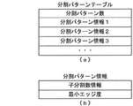
- FIG. 7A is a diagram illustrating an example of contents set in the division pattern table.
- the division pattern table is table information indicating the correspondence between the edge degree of the basic area and the number of child divisions. As shown in FIG. 7A, the number of division patterns and one or more pieces of division pattern information are set in the division pattern table.
- the division pattern number indicates the number of child division number patterns.
- the number of division patterns is 3.
- the division pattern information is set for the number of division patterns.
- FIG. 7B is a diagram illustrating an example of contents set in the division pattern information. As shown in FIG. 7B, the division pattern information is set with the child division number information and the minimum edge degree. The content of the child division number information set in the division pattern information is the same as the content of the child division number information registered in the original image DB 12b.
- the minimum edge degree is the minimum value of the edge degree necessary for dividing the basic region by the number of child divisions included in the child division number information.
- N is an integer of 1 or more
- Each division pattern information is set so that the edge degree of the division pattern information N + 1> the edge degree of the division pattern information N.
- the number of child divisions, the number of child horizontal divisions, the number of child vertical divisions and the minimum edge degree (an example of preset values in the present invention) of the division pattern information 1 are, for example, 4 2, 2, and 3.
- the division pattern information 2 is 9, 3, 3, 7 for example.
- the division pattern information 3 is 16, 4, 4, 20, for example.
- the content of the child division number information when the basic region is divided matches the content of the child division number information included in any of the division pattern information. .
- the number of division patterns and each piece of division pattern information are performed by, for example, an administrator of the mosaic image providing server 1.
- the number of division patterns may be one or more. Further, the number of child horizontal divisions and the number of child vertical divisions may not be the same. Further, as long as the condition of the above equation is satisfied, the child division number information and the minimum edge degree can be arbitrarily set. For example, when the number of division patterns is 1, all basic areas whose edge degrees are equal to or higher than the minimum edge degree included in the division pattern information 1 are divided into the same number of child areas. In addition, when the number of division patterns is two or more, a basic region with a higher edge degree is divided into more child regions.
- the storage unit 12 stores various data such as an HTML document, an XML document, image data, text data, and an electronic document for displaying a Web page.
- the storage unit 12 stores various setting values set by an administrator or the like.
- the setting value includes a threshold value for determining whether the color of the posted image is close to the color of the divided area.
- the storage unit 12 stores various programs such as an operating system, a WWW (World Wide Web) server program, a DBMS (Data Base Management System), and a mosaic image providing program.
- the mosaic image providing program is a program for executing processing related to a mosaic image such as registration of an original image, acquisition of a posted image, generation of mosaic image display data, and the like.
- the various programs may be acquired from other server devices or the like via the network NW, or may be recorded on a recording medium such as a DVD (Digital Versatile Disc) and read via the drive device. You may do it.
- the input / output interface 13 performs interface processing between the communication unit 11 and the storage unit 12 and the system control unit 14.
- the system control unit 14 includes a CPU 14a, a ROM (Read Only Memory) 14b, a RAM (Random Access Memory) 14c, and the like.
- the system control unit 14 functions as a specifying unit, a dividing unit, an acquiring unit, a determining unit, and a presenting unit in the present invention by the CPU 14a reading and executing various programs.
- the mosaic image providing server 1 may be configured by a plurality of server devices.
- a server device that performs processing related to registration of original images, acquisition of posted images, and generation of mosaic image display data
- a server device that transmits a Web page in response to a request from the user terminal 2 a server device that manages a database, and the like
- they may be connected to each other via a LAN or the like.
- FIG. 8 is a flowchart showing a processing example in the original image registration processing of the system control unit 14 of the mosaic image providing server 1 according to the present embodiment.
- the administrator of the mosaic image providing server 1 registers the original image by operating the management terminal device connected to the mosaic image providing server 1. Specifically, the administrator selects the original image data and inputs the basic horizontal division number and the basic vertical division number. Then, the management terminal device transmits an original image registration request including the original image data, the basic horizontal division number, and the basic vertical division number to the mosaic image providing server 1. For example, the user may be able to post the original image. In this case, the user terminal 2 of the user who posts the original image transmits an original image registration request.
- the original image registration process is started when the mosaic image providing server 1 receives an original image registration request. This original image registration process is executed in advance before a post image reception process described later. Then, by executing the original image registration process, it is possible to assign a post image in the post image reception process.
- the system control unit 14 In the original image registration process, the system control unit 14 generates a new original image ID. Next, the system control unit 14 generates basic division number information based on the basic horizontal division number and the basic vertical division number included in the received original image registration request. Then, the system control unit 14 associates the new original image ID, the original image data included in the original image registration request, and the basic division number information each time it is generated, and registers them in the original image DB 12b (step S11).
- the system control unit 14 generates a new mosaic image ID.
- the system control unit 14 associates the new mosaic image ID with the original image ID and registers them in the mosaic image DB 12d (step S12). Further, the system control unit 14 develops a bitmap image of the original image in the RAM 14c based on the original image data.
- the system control unit 14 divides the original image into a plurality of basic areas.
- the system control unit 14 sets 0 to the index Y1 of the basic area (step S13).
- the system control unit 14 sets 0 to the index X1 of the basic area (step S14).
- the system control unit 14 specifies the basic area (X1, Y1) (step S15). Specifically, the system control unit 14 acquires the number of vertical and horizontal pixels of the original image from the registered original image data.
- the system control unit 14 determines the basic area (X1, X1) based on the number of vertical and horizontal pixels of the original image, the basic horizontal division number and the basic vertical division number indicated by the registered basic division number information, and the indexes X1 and Y1. The coordinate range of the pixel included in Y1) is calculated.
- the system control unit 14 calculates the pixel edge degree of each pixel included in the divided area (X1, Y1) (step S16). Specifically, the system control unit 14 acquires the value of each pixel included in the divided area (X1, Y1) from the bitmap image of the original image developed in the RAM 14c. Then, the system control unit 14 calculates the pixel edge degree by, for example, a calculation method represented by Expression 1.
- the system control unit 14 calculates the edge degrees of the divided regions (X1, Y1) based on the calculated pixel edge degrees. For example, the system control unit 14 calculates the edge degree by the calculation method represented by Equation 2. Then, the system control unit 14 registers the calculated edge degree in the original image DB 12b in association with the new original image ID and the indexes X1 and Y1 (step S17).
- the system control unit 14 associates the child division number information of the basic area (X1, Y1) with the new original image ID and the indexes X1 and Y1 based on the calculated edge degree and the division pattern table. Are registered in the original image DB 12b (step S18). Specifically, the system control unit 14 compares the minimum edge degree included in the division pattern information with the calculated edge degree in ascending order of the index value of the division pattern information. Here, when the calculated edge degree is smaller than the minimum edge degree included in the division pattern information 1, the system control unit 14 has all the child division number, the child horizontal division number, and the child vertical division number being 1. Register child division number information.
- the system control unit 14 registers the child division number information included in the division pattern information.
- the system control unit 14 specifies the basic region including the edge as the specifying unit.
- the system control unit 14 registers the assigned image information (X1, Y1) in the mosaic image DB 12d in association with the new mosaic image ID and the indexes X1 and Y1 (step S19). At this time, the system control unit 14 makes the number of assigned image numbers included in the assigned image information (X1, Y1) the same as the number of child divisions included in the registered child division number information. Further, the system control unit 14 sets an invalid number indicating an unallocated area for each allocated image number.
- the system control unit 14 sets 0 to the index Y2 of the child area (step S20).
- the system control unit 14 sets 0 to the index X2 of the child area (step S21).
- the system control unit 14 specifies divided areas (X1, Y1) (X2, Y2) (step S22). Specifically, the system control unit 14 determines the number of vertical and horizontal pixels of the original image, the basic horizontal division number and the basic vertical division number included in the registered basic division number information, and the child horizontal number included in the registered child division number information.
- the coordinate range of the pixels included in the divided regions (X1, Y1) (X2, Y2) is calculated.
- the region (X1, Y1) (X2, Y2) is a child region.
- the system control unit 14 calculates representative color values of the divided areas (X1, Y1) (X2, Y2) (step S23). For example, the system control unit 14 acquires the values of the pixels included in the divided areas (X1, Y1) (X2, Y2) from the bitmap image of the original image developed in the RAM 14c. Next, the system control unit 14 adds the acquired pixel values for each of the R, G, and B basic colors. Next, the system control unit 14 divides the sum of the pixel values for each basic color by the total number of pixels included in each of the divided regions (X1, Y1) (X2, Y2). The average of the pixel values for each basic color obtained by this calculation is the representative color value. Next, the system control unit 14 registers the calculated representative color value in the original image DB 12b in association with the new original image ID and the indexes X1, Y1, X2, and Y2.
- step S24 the system control unit 14 adds 1 to the index X2 (step S24).
- step S25 the system control unit 14 determines whether or not the index X2 is less than the child horizontal division number (step S25). At this time, if the system control unit 14 determines that the index X2 is less than the child horizontal division number (step S25: YES), the system control unit 14 proceeds to step S22. On the other hand, when the system control unit 14 determines that the index X2 is not less than the child horizontal division number (step S25: NO), the system control unit 14 adds 1 to the index Y2 (step S26). Next, the system control unit 14 determines whether or not the index Y2 is less than the number of child vertical divisions (step S27).
- step S27 if the system control unit 14 determines that the index Y2 is less than the number of child vertical divisions (step S27: YES), the system control unit 14 proceeds to step S21.
- the system control unit 14 registers the representative color values of the basic area (X1, Y1) or the representative color values of the child areas included in the basic area (X1, Y1) by repeating the processes of steps S21 to S27. .
- the edge degree of the basic area is equal to or higher than the minimum edge degree included in the division pattern information 1
- the system control unit 14 divides the basic area into a plurality of child areas as a dividing unit.
- step S27: NO the system control unit 14 adds 1 to the index X1 (step S28).
- step S29 the system control unit 14 determines whether the index X1 is less than the basic horizontal division number. At this time, if the system control unit 14 determines that the index X1 is less than the basic horizontal division number (step S29: YES), the system control unit 14 proceeds to step S15. On the other hand, when the system control unit 14 determines that the index X1 is not less than the basic horizontal division number (step S29: NO), the system control unit 14 adds 1 to the index Y1 (step S30).
- step S31 determines whether the index Y1 is less than the basic vertical division number. At this time, if the system control unit 14 determines that the index Y1 is less than the basic vertical division number (step S31: YES), the system control unit 14 proceeds to step S14.
- the system control unit 14 registers the representative color values of all the divided areas by repeating the processes of steps S14 to S31.
- the system control unit 14 determines that the index Y1 is not less than the basic vertical division number (step S31: NO), the system control unit 14 generates empty mosaic image display data, and the generated mosaic image display data is newly set. Is registered in the mosaic image DB 12d in association with a unique mosaic image ID (step S32).
- the empty mosaic image display data is mosaic image display data in which no img tag including the URL of the posted image data is set.
- the system control unit 14 performs child horizontal division for cells corresponding to the basic region divided into child regions.
- Mosaic image display data is generated so as to be further divided into a plurality of cells according to the number and the number of child vertical divisions.
- the system control unit 14 generates an HTML document of the image posting / mosaic image display page 400 (step S33).
- the image posting / mosaic image display page 400 is a Web page for posting an image and also a Web page on which a mosaic image is displayed.
- the system control unit 14 stores the generated HTML document in the storage unit 12.
- the system control unit 14 sets a hyperlink to the generated HTML document (step S34). For example, the system control unit 14 adds an a tag including the URL of the HTML document of the image posting / mosaic image display page 400 to the HTML document of the top page of the website of the mosaic image providing system S. Thereby, the user can post images and browse mosaic images.
- the system control unit 14 ends the original image registration process.
- FIG. 9 is a diagram showing a screen display example of the image posting / mosaic image display page 400 according to the present embodiment.
- the image posting / mosaic image display page 400 includes a message unit 410, a posted image transmission unit 420, a mosaic image display unit 430, and the like.
- the message unit 410 for example, information such as notifications regarding products and services on a site related to the mosaic image providing system S is displayed.
- the posted image transmission unit 420 displays various widgets (operation elements) for posting images. For example, an input field for designating a path name of posted image data, a reference button for displaying a dialog for selecting posted image data from the image data stored in the user terminal 2, and a posted image data A transmission button or the like for transmission is displayed.
- a mosaic image generated by the images posted so far is displayed.
- a mosaic image 300c is displayed as an example of the mosaic image.
- the mosaic image 300c is a mosaic image generated by assigning a posted image to a part of the divided areas shown in FIG. If no image has been posted yet after the original image registration process is completed, the mosaic image is not displayed on the mosaic image display unit 430.
- the system control unit 14 sets the user ID of the user who posted the posted image in the mosaic image display data.
- the user terminal 2 transmits a request including the user ID of the user who posted the posted image to the mosaic image providing server 1.
- the system control unit 14 acquires necessary information from the member information corresponding to the user ID included in the received request and transmits it to the user terminal 2. Then, the user terminal 2 displays the received information.
- FIG. 10 is a flowchart showing a processing example in the posted image reception process of the system control unit 14 of the mosaic image providing server 1 according to the present embodiment.
- the posted image transmission unit 420 of the image posting / mosaic image display page 400 when the user specifies posted image data and selects a transmission button, the user terminal 2 transmits a posting request to the mosaic image providing server 1.
- the posting request includes the specified posting image data, the user ID of the user who performed the operation, and the mosaic image ID of the mosaic image to be generated.
- the post image receiving process is started when the mosaic image providing server 1 receives a post request as an acquisition unit.
- the system control unit 14 determines a divided area to which the posted image is allocated as a determination unit by the processing of steps S51 to S56. First, the system control unit 14 calculates a representative color value of a posted image (hereinafter referred to as “processed posted image”) indicated by posted image data included in the posted request (step S51). This calculation method is the same as that in step S23 in the original image registration process.
- the system control unit 14 performs exclusive control using, for example, a mutex, and performs a lock operation when acquiring the authority to execute the processing (critical session) after step S52. Thereby, the system control unit 14 prevents a plurality of processes from executing critical sessions simultaneously.
- the system control unit 14 initializes the assignment candidate list and sets it in the RAM 14c (step S52).
- the assignment candidate list is a list of divided areas (hereinafter referred to as “candidate areas”) that satisfy the conditions for assigning the processing target posted image.
- the candidate area refers to a divided area where the difference in representative color value from the processing target posted image is equal to or less than a threshold value.
- X1, Y1, X2, and Y2 that are indexes of candidate areas and the difference value of the representative color value from the processing target posted image are registered in association with each other.
- step S53 the system control unit 14 executes a candidate area search process described later (step S53).
- candidate areas are searched from unallocated areas, and the searched candidate areas are registered in the allocation candidate list.
- the system control unit 14 determines whether or not a candidate area has been searched (step S54). Specifically, the system control unit 14 determines whether or not one or more sets of candidate region indexes and difference values are registered in the allocation candidate list. At this time, if the index and the difference value of the candidate area are not registered in the allocation candidate list, the system control unit 14 determines that the candidate area could not be searched (step S54: NO). In this case, the system control unit 14 transmits a posting rejection message to the user terminal 2 that has transmitted the posting request (step S55). The posting rejection message is a message indicating that image posting has been rejected. The user terminal 2 displays the received post rejection message on the screen. When completing the process of step S55, the system control unit 14 ends the posted image reception process.
- the system control unit 14 determines that the candidate area can be searched (step S54: YES). In this case, the system control unit 14 assigns a candidate area having the smallest difference in representative color value from the processing target posted image among the searched candidate areas to a divided area (hereinafter, “allocation target area” to which the processing target posted image is assigned. ”) (Step S56). Specifically, the system control unit 14 searches for the smallest value from the difference values registered in the assignment candidate list. Then, the system control unit 14 acquires the indexes X1, X2, Y1, and Y2 associated with the smallest difference value from the allocation candidate list as the allocation target area index.
- the system control unit 14 adds 1 to the number of posts registered in the posted image DB 12c in association with the mosaic image ID (hereinafter referred to as “target mosaic image ID”) included in the posting request, and calculates the number of posts. Update (step S57).
- the system control unit 14 sets the updated number of posts in the image number of the processing target posted image (step S58).
- the system control unit 14 associates post image information including the image number, the user ID and post image data included in the post request, and the representative color value of the processing target post image with the target mosaic image ID, and the post image DB 12c. (Step S59).
- the system control unit 14 rewrites the allocation image number of the allocation target area registered in the mosaic image DB 12d in association with the target mosaic image ID to the image number of the processing target posted image (step S60).
- the system control unit 14 updates the mosaic image display data registered in the mosaic image DB 12d in association with the target mosaic image ID (step S61). Specifically, the system control unit 14 sets an img tag including the URL of the posted image data of the processing target posted image in a cell corresponding to the index of the allocation target region in the mosaic image display data.
- the system control unit 14 generates an HTML document of the image posting / mosaic image display page 400 including the updated mosaic image display data, and stores the HTML document in the storage unit 12 (step S62).
- the system control unit 14 transmits the generated HTML document to the user terminal 2 that has transmitted the posting request (step S63).
- the system control unit 14 performs an unlock operation so that another process can execute the critical session.
- the system control unit 14 ends the posted image reception process.
- the user terminal 2 displays the image posting / mosaic image display page 400 on the screen based on the received HTML document.
- the system control unit 14 transmits a request including the URL of the posted image data to the mosaic image providing server 1 based on the img tag included in the mosaic image display data.
- the system control unit 14 acquires the mosaic image ID and the image number from the URL included in the received request.
- the system control unit 14 acquires posted image data corresponding to the acquired mosaic image ID and image number from the posted image DB 12c.
- the system control unit 14 transmits the acquired posted image data to the user terminal 2.
- the user terminal 2 displays the posted image in the mosaic image display unit 430 of the image posting / mosaic image display page 400 based on the acquired posted image data. Thereby, for example, a mosaic image as shown in FIG. 9 is displayed.
- the system control unit 14 causes the user terminal 2 to present a mosaic image as a presentation unit by transmitting the mosaic image display data.
- FIG. 11 is a flowchart illustrating a processing example in the candidate area search process of the system control unit 14 of the mosaic image providing server 1 according to the present embodiment.
- the system control unit 14 acquires an original image ID (hereinafter referred to as “target original image ID”) corresponding to the target mosaic image ID from the mosaic image DB 12d.
- the system control unit 14 acquires basic division number information corresponding to the target original image ID from the original image DB 12b (step S101).
- the system control unit 14 sets 0 to the index Y1 of the basic area (step S102).
- the system control unit 14 sets 0 to the index X1 of the basic area (step S103).
- the system control unit 14 acquires child division number information from the basic area information (X1, Y1) registered in the original image DB 12b in association with the target original image ID (step S104).
- the system control unit 14 sets 0 to the index Y2 of the child area (step S105).
- the system control unit 14 sets 0 to the child area index X2 (step S106).
- the system control unit 14 determines whether or not the divided areas (X1, Y1) (X2, Y2) are unallocated areas (step S107). Specifically, the system control unit 14 determines whether the assigned image number (X1, Y1) (X2, Y2) registered in the mosaic image DB 12d in association with the target mosaic image ID is a number indicating an unassigned area. Determine whether.
- the system control unit 14 determines with it being an area
- Equation 3 Diff is the difference.
- R1, G1, and B1 are representative color values of R, G, and B in the divided areas (X1, Y1) (X2, Y2).
- R2, G2, and B2 are the representative color values of R, G, and B of the processing target posted image.
- the system control unit 14 calculates the square of the difference calculated for each basic color, and instead of adding the calculation results, takes the absolute value of the difference calculated for each basic color, and calculates the absolute value. You may add them together.
- step S109 determines whether or not the calculated difference value is equal to or less than a threshold value.
- step S109: YES the system control unit 14 determines the divided regions (X1, Y1) (X2, Y2) as candidate regions (steps). S110). Specifically, the system control unit 14 associates the indexes X1, Y1, X2, and Y2 with the calculated difference values and registers them in the assignment candidate list. Then, the system control unit 14 proceeds to step S111.
- step S107 if the assigned image number (X1, Y1) (X2, Y2) is not a number indicating an unassigned area, the system control unit 14 has not assigned the divided area (X1, Y1) (X2, Y2). It determines with it not being an allocation area
- step S109 when the system control unit 14 determines that the difference value is not equal to or less than the threshold value (step S109: NO), the system control unit 14 proceeds to step S111.
- step S111 the system control unit 14 adds 1 to the index X2.
- step S112 determines whether or not the index X2 is less than the number of child horizontal divisions included in the acquired child division number information (step S112). At this time, if the system control unit 14 determines that the index X2 is less than the child horizontal division number (step S112: YES), the system control unit 14 proceeds to step S107. On the other hand, when the system control unit 14 determines that the index X2 is not less than the child horizontal division number (step S112: NO), the system control unit 14 adds 1 to the index Y2 (step S113).
- the system control unit 14 determines whether or not the index Y2 is less than the number of child vertical divisions included in the acquired child division number information (step S114). At this time, if the system control unit 14 determines that the index Y2 is less than the number of child vertical divisions (step S114: YES), the system control unit 14 proceeds to step S106.
- the system control unit 14 searches for candidate regions from the child regions included in the basic region (X1, Y1) or the basic region (X1, Y1) by repeating the processing of steps S106 to S114.
- step S114 When the system control unit 14 determines that the index Y2 is not less than the number of child vertical divisions (step S114: NO), the system control unit 14 adds 1 to the index X1 (step S115). Next, the system control unit 14 determines whether or not the index X1 is less than the basic horizontal division number included in the acquired basic division number information (step S116). At this time, if the system control unit 14 determines that the index X1 is less than the basic horizontal division number (step S116: YES), the system control unit 14 proceeds to step S104. On the other hand, when the system control unit 14 determines that the index X1 is not less than the basic horizontal division number (step S116: NO), the system control unit 14 adds 1 to the index Y1 (step S117).
- step S118 determines whether or not the index Y1 is less than the basic vertical division number included in the acquired basic division number information. At this time, if the system control unit 14 determines that the index Y1 is less than the basic vertical division number (step S118: YES), the system control unit 14 proceeds to step S103.
- the system control unit 14 searches for candidate areas from all unassigned by repeating the processing of steps S103 to S118.
- step S118 NO
- the system control unit 14 determines that the index Y1 is not less than the basic vertical division number
- the system control unit 14 of the mosaic image providing server 1 specifies an area including an image edge from a plurality of basic areas, and further specifies a plurality of specified basic areas. Area that allocates the posted image from among the basic area that is not divided into child areas and the child area created by the division. And a mosaic image in which the acquired posted images are arranged is presented to the user based on the determined assignment.
- the basic area including an edge that contributes to improving the visibility of the original image among the plurality of basic areas is divided into smaller child areas, so that the number of the divided areas necessary for completing the mosaic image is reduced and the original image is reduced. It is possible to provide a mosaic image with high visibility of the pattern.
- the system control unit 14 calculates an edge degree indicating the degree of edge included in the image of the basic area, and specifies an area where the edge degree is equal to or greater than a preset threshold as a basic area including the edge.
- an area including an edge can be determined by a preset value.
- system control unit 14 divides the identified basic region so that the basic region having a higher calculated edge degree has a larger number of divisions.
- the mosaic image providing server 1 calculates the difference in representative color value from the posted image for all the divided areas to which the posted image is not assigned.
- the system control unit 14 displays a list indicating divided areas in ascending order of R representative color values, a list indicating divided areas in ascending order of G representative color values, and a list indicating divided areas in ascending order of B representative color values.
- the system control unit 14 When the system control unit 14 receives the posted image data and calculates the representative value of the posted image, the system control unit 14 sets the minimum value and the maximum value of the representative value that have a difference from the representative value of the posted image equal to or less than the threshold value as R, G, Calculate for each B.
- the threshold value at this time may be different from the threshold value used when the difference is calculated by Equation 3.
- the system control unit 14 specifies, by using the generated list, a range of divided areas in which the difference between the representative value and the representative value of the posted image is equal to or less than a threshold value by, for example, a binary search method.
- the system control unit 14 executes this for R, G, and B.
- the system control unit 14 sets, as candidate areas, divided areas in which the difference in representative value from the posted image is equal to or less than the threshold in all of R, G, and B.
- the mosaic image providing server 1 determines a candidate area to which the posted image is allocated from among the unallocated areas. However, the mosaic image providing server 1 may determine a candidate area to which the posted image is assigned regardless of whether the posted image has already been assigned. For example, if the color of the processing target posted image to be assigned is closer to the color of the divided region than the color of the posted image already assigned to the divided region, the mosaic image providing server 1 May be assigned to the divided area, and the posted image assigned to the divided area may be assigned to the unallocated area.
- the mosaic image providing server 1 has determined the divided area having the smallest difference in representative color value from the posted image as the allocation target area. For example, the difference in the representative color value from the posted image. Any divided area may be determined as the allocation target area from among the divided areas having a threshold value equal to or less than the threshold value.
- the mosaic image providing server 1 assigns each posted image to one divided area, but may assign it to a plurality of areas, for example.
- the mosaic image providing server 1 may assign the same posted image to a plurality of areas from among the divided areas in which the difference in the representative color value from the posted image is equal to or less than the threshold value.
- the mosaic image providing server 1 has determined the allocation target area based on the representative color value of the posted image and the representative color value of the divided area.
- the allocation target area may be determined based on the pattern included in the divided area. For example, the mosaic image providing server 1 calculates the degree of coincidence indicating the coincidence between the pattern of the posted image and the pattern included in the divided region, and assigns an assignment target from among the divided regions where the degree of coincidence is equal to or greater than a preset threshold. An area may be determined. Further, for example, the mosaic image providing server 1 calculates the degree of coincidence of the image itself including the pattern and the color between the posted image and the divided area, and the divided area where the degree of coincidence is equal to or higher than a preset threshold value.
- the allocation target area may be determined from the inside.
- the mosaic image providing server 1 transmits an HTML document including mosaic image display data to the user terminal 2 in order to display the mosaic image on the user terminal 2.
- the mosaic image providing server 1 may transmit the image data of the mosaic image itself to the user terminal 2.
- the mosaic image providing server 1 is assigned based on, for example, the posted image data acquired so far and registered in the posted image DB 12c, and the assigned image number registered in the mosaic image DB 12d. The image data of the mosaic image in which each posted image is arranged at the position of the area is generated.
- the mosaic image providing server 1 can use images posted from a plurality of users for generating display data of one mosaic image.
- the mosaic image providing server 1 may generate display data of a mosaic image using only an image posted from one user, for example.
- the mosaic image providing server 1 is provided with specifying means, dividing means, obtaining means, determining means, and presenting means, and the mosaic image providing server 1 transmits display data to the user terminal 2.
- a mosaic image was presented by the user terminal 2.
- an apparatus such as the user terminal 2 is provided with a specifying unit, a dividing unit, an acquiring unit, a determining unit, and a presenting unit. You may perform a division
Landscapes
- Engineering & Computer Science (AREA)
- Physics & Mathematics (AREA)
- General Physics & Mathematics (AREA)
- Theoretical Computer Science (AREA)
- Multimedia (AREA)
- Signal Processing (AREA)
- Image Processing (AREA)
- Editing Of Facsimile Originals (AREA)
Priority Applications (4)
| Application Number | Priority Date | Filing Date | Title |
|---|---|---|---|
| US13/884,353 US8599287B2 (en) | 2011-06-24 | 2012-04-02 | Image providing device, image processing method, image processing program, and recording medium for forming a mosaic image |
| CN201280007326.6A CN103348379B (zh) | 2011-06-24 | 2012-04-02 | 图像提供装置以及图像处理方法 |
| ES12802862.8T ES2548055T3 (es) | 2011-06-24 | 2012-04-02 | Dispositivo de proporción de imágenes, método de procesamiento de imágenes, programa de procesamiento de imágenes y medio de grabación |
| EP12802862.8A EP2624203B1 (de) | 2011-06-24 | 2012-04-02 | Bildgebungsvorrichtung, bildverarbeitungsverfahren, bildverarbeitungsprogramm und aufzeichnungsmedium |
Applications Claiming Priority (2)
| Application Number | Priority Date | Filing Date | Title |
|---|---|---|---|
| JP2011-140290 | 2011-06-24 | ||
| JP2011140290A JP5144789B2 (ja) | 2011-06-24 | 2011-06-24 | 画像提供装置、画像処理方法、画像処理プログラム及び記録媒体 |
Publications (1)
| Publication Number | Publication Date |
|---|---|
| WO2012176523A1 true WO2012176523A1 (ja) | 2012-12-27 |
Family
ID=47422371
Family Applications (1)
| Application Number | Title | Priority Date | Filing Date |
|---|---|---|---|
| PCT/JP2012/058826 Ceased WO2012176523A1 (ja) | 2011-06-24 | 2012-04-02 | 画像提供装置、画像処理方法、画像処理プログラム及び記録媒体 |
Country Status (6)
| Country | Link |
|---|---|
| US (1) | US8599287B2 (de) |
| EP (1) | EP2624203B1 (de) |
| JP (1) | JP5144789B2 (de) |
| CN (1) | CN103348379B (de) |
| ES (1) | ES2548055T3 (de) |
| WO (1) | WO2012176523A1 (de) |
Families Citing this family (16)
| Publication number | Priority date | Publication date | Assignee | Title |
|---|---|---|---|---|
| US20110050723A1 (en) * | 2009-09-03 | 2011-03-03 | Sony Corporation | Image processing apparatus and method, and program |
| US9218107B1 (en) | 2011-12-30 | 2015-12-22 | hopTo Inc. | Cloud-based text management for cross-platform display |
| US9367931B1 (en) | 2011-12-30 | 2016-06-14 | hopTo Inc. | Motion vectors for cross-platform display |
| US9223534B1 (en) | 2011-12-30 | 2015-12-29 | hopTo Inc. | Client side detection of motion vectors for cross-platform display |
| US9454617B1 (en) | 2011-12-30 | 2016-09-27 | hopTo Inc. | Client rendering |
| US9106612B1 (en) | 2012-05-18 | 2015-08-11 | hopTo Inc. | Decomposition and recomposition for cross-platform display |
| US9124562B1 (en) | 2012-05-18 | 2015-09-01 | hopTo Inc. | Cloud-based decomposition and recomposition for cross-platform display |
| US8817339B2 (en) * | 2012-08-22 | 2014-08-26 | Top Image Systems Ltd. | Handheld device document imaging |
| US9516330B2 (en) * | 2013-02-06 | 2016-12-06 | Broadcom Corporation | Virtual field buffer based decoding |
| US9430134B1 (en) | 2013-03-15 | 2016-08-30 | hopTo Inc. | Using split windows for cross-platform document views |
| US9292157B1 (en) | 2013-03-15 | 2016-03-22 | hopTo Inc. | Cloud-based usage of split windows for cross-platform document views |
| JP6674094B2 (ja) * | 2016-03-31 | 2020-04-01 | 富士通株式会社 | 領域抽出プログラム、領域抽出方法、および領域抽出装置 |
| CN106131648A (zh) * | 2016-07-27 | 2016-11-16 | 深圳Tcl数字技术有限公司 | 智能电视的画面显示处理方法及装置 |
| KR20200107945A (ko) * | 2018-01-12 | 2020-09-16 | 소니 주식회사 | 정보 처리 장치 및 방법 |
| CN111415298B (zh) * | 2020-03-20 | 2023-06-02 | 北京百度网讯科技有限公司 | 图像拼接方法、装置、电子设备及计算机可读存储介质 |
| CN115578130B (zh) * | 2022-11-21 | 2023-04-07 | 成都智元汇信息技术股份有限公司 | 全图扫描生成广告位信息展示组件方法 |
Citations (4)
| Publication number | Priority date | Publication date | Assignee | Title |
|---|---|---|---|---|
| JPH11341266A (ja) * | 1998-05-29 | 1999-12-10 | Canon Inc | 画像処理方法及びその装置 |
| JP2000295453A (ja) * | 1999-04-02 | 2000-10-20 | Canon Inc | 画像処理方法、画像処理装置及び記憶媒体 |
| JP2001238067A (ja) * | 2000-02-25 | 2001-08-31 | Canon Inc | 画像処理方法及び装置 |
| JP2011078078A (ja) * | 2009-09-03 | 2011-04-14 | Sony Corp | 画像処理装置および方法、並びにプログラム |
Family Cites Families (15)
| Publication number | Priority date | Publication date | Assignee | Title |
|---|---|---|---|---|
| US6137498A (en) * | 1997-01-02 | 2000-10-24 | Runaway Technology, Inc. | Digital composition of a mosaic image |
| US6335985B1 (en) * | 1998-01-07 | 2002-01-01 | Kabushiki Kaisha Toshiba | Object extraction apparatus |
| US6556210B1 (en) | 1998-05-29 | 2003-04-29 | Canon Kabushiki Kaisha | Image processing method and apparatus therefor |
| US6927874B1 (en) * | 1999-04-02 | 2005-08-09 | Canon Kabushiki Kaisha | Image processing method, apparatus and storage medium therefor |
| JP2004527933A (ja) * | 2001-01-09 | 2004-09-09 | メシュリム、ジッシャ、ゴルドクラング | 装飾画像をテキスト及び/もしくは絵模様で代替する改善された装置及び方法 |
| JP3944738B2 (ja) * | 2003-03-18 | 2007-07-18 | ソニー株式会社 | 画像処理装置および方法、記録媒体、並びにプログラム |
| CA2442603C (en) * | 2003-10-01 | 2016-11-22 | Aryan Saed | Digital composition of a mosaic image |
| US7545984B1 (en) * | 2004-12-16 | 2009-06-09 | Nvidia Corporation | Quantifying graphics image difference |
| JPWO2006082979A1 (ja) * | 2005-02-07 | 2008-06-26 | 松下電器産業株式会社 | 画像処理装置および画像処理方法 |
| WO2009090901A1 (ja) * | 2008-01-15 | 2009-07-23 | Comap Incorporated | モザイク画像生成装置、方法及びプログラム |
| JP4191791B1 (ja) | 2008-06-18 | 2008-12-03 | コマップ株式会社 | モザイク画像提供装置、方法及びプログラム |
| KR100965720B1 (ko) * | 2008-02-26 | 2010-06-24 | 삼성전자주식회사 | 모자이크 영상을 생성하는 방법 및 이를 위한 장치 |
| US20110050723A1 (en) | 2009-09-03 | 2011-03-03 | Sony Corporation | Image processing apparatus and method, and program |
| CA2785186C (en) * | 2009-12-25 | 2013-08-06 | Rakuten, Inc. | Image generation device, image generation method, image generation program and recording medium |
| JP5113930B1 (ja) * | 2011-06-24 | 2013-01-09 | 楽天株式会社 | 画像提供装置、画像処理方法、画像処理プログラム及び記録媒体 |
-
2011
- 2011-06-24 JP JP2011140290A patent/JP5144789B2/ja active Active
-
2012
- 2012-04-02 EP EP12802862.8A patent/EP2624203B1/de active Active
- 2012-04-02 US US13/884,353 patent/US8599287B2/en active Active
- 2012-04-02 ES ES12802862.8T patent/ES2548055T3/es active Active
- 2012-04-02 WO PCT/JP2012/058826 patent/WO2012176523A1/ja not_active Ceased
- 2012-04-02 CN CN201280007326.6A patent/CN103348379B/zh active Active
Patent Citations (4)
| Publication number | Priority date | Publication date | Assignee | Title |
|---|---|---|---|---|
| JPH11341266A (ja) * | 1998-05-29 | 1999-12-10 | Canon Inc | 画像処理方法及びその装置 |
| JP2000295453A (ja) * | 1999-04-02 | 2000-10-20 | Canon Inc | 画像処理方法、画像処理装置及び記憶媒体 |
| JP2001238067A (ja) * | 2000-02-25 | 2001-08-31 | Canon Inc | 画像処理方法及び装置 |
| JP2011078078A (ja) * | 2009-09-03 | 2011-04-14 | Sony Corp | 画像処理装置および方法、並びにプログラム |
Non-Patent Citations (4)
| Title |
|---|
| KEITA FUNABASHI ET AL.: "Edge Tokucho Database Seisei no Tameno Realtime Dogazo ni Taisuru Photo Mosaic", EIZO MEDIA SHORI SYMPOSIUM DAI 14 KAI SYMPOSIUM SHIRYO, 7 October 2009 (2009-10-07), pages 89 - 90, XP008169365 * |
| KOJIMA K. ET AL.: "Decorative Photomosaics Respecting Human Visual Perception", TRANSACTIONS OF INFORMATION PROCESSING SOCIETY OF JAPAN, vol. 49, no. 7, 15 July 2008 (2008-07-15), pages 2703 - 2711, XP055075725 * |
| See also references of EP2624203A4 * |
| SHIN'ICHI DOI ET AL.: "P2P Network o Riyo shita Photo Paint Tool", SYMPOSIUM ON MULTIMEDIA, DISTRIBUTED, COOPERATIVE AND MOBILE SYSTEMS, vol. 2009, no. 1, 8 July 2009 (2009-07-08), pages 1855 - 1862, XP008170078 * |
Also Published As
| Publication number | Publication date |
|---|---|
| CN103348379B (zh) | 2016-04-13 |
| JP5144789B2 (ja) | 2013-02-13 |
| US8599287B2 (en) | 2013-12-03 |
| EP2624203B1 (de) | 2015-07-01 |
| EP2624203A1 (de) | 2013-08-07 |
| CN103348379A (zh) | 2013-10-09 |
| US20130229548A1 (en) | 2013-09-05 |
| JP2013009146A (ja) | 2013-01-10 |
| EP2624203A4 (de) | 2014-01-01 |
| ES2548055T3 (es) | 2015-10-13 |
Similar Documents
| Publication | Publication Date | Title |
|---|---|---|
| JP5144789B2 (ja) | 画像提供装置、画像処理方法、画像処理プログラム及び記録媒体 | |
| JP5113929B1 (ja) | 画像提供装置、画像処理方法、画像処理プログラム及び記録媒体 | |
| US11681745B2 (en) | Digital image presentation | |
| CN103700122B (zh) | 图像生成装置及图像生成方法 | |
| JP5113930B1 (ja) | 画像提供装置、画像処理方法、画像処理プログラム及び記録媒体 | |
| CN111104608A (zh) | 一种网页数据处理方法以及相关装置 | |
| CA2785186C (en) | Image generation device, image generation method, image generation program and recording medium | |
| US20230273953A1 (en) | Digital image presentation | |
| JP6281381B2 (ja) | サーバ装置、プログラム及び推薦情報提供方法 | |
| JP2021149295A (ja) | 画像処理装置及びプログラム | |
| JP5046119B2 (ja) | プログラム、画像間変化箇所判読支援動画生成方法、及び画像間変化箇所判読支援動画生成装置 | |
| JP2006350407A (ja) | 白黒写真のカラー化装置及び、白黒写真のカラー化プログラム、並びに白黒写真のカラー化方法 |
Legal Events
| Date | Code | Title | Description |
|---|---|---|---|
| 121 | Ep: the epo has been informed by wipo that ep was designated in this application |
Ref document number: 12802862 Country of ref document: EP Kind code of ref document: A1 |
|
| WWE | Wipo information: entry into national phase |
Ref document number: 2012802862 Country of ref document: EP |
|
| WWE | Wipo information: entry into national phase |
Ref document number: 13884353 Country of ref document: US |
|
| NENP | Non-entry into the national phase |
Ref country code: DE |