WO2012176603A1 - Structure d'enveloppe de substrat - Google Patents
Structure d'enveloppe de substrat Download PDFInfo
- Publication number
- WO2012176603A1 WO2012176603A1 PCT/JP2012/064140 JP2012064140W WO2012176603A1 WO 2012176603 A1 WO2012176603 A1 WO 2012176603A1 JP 2012064140 W JP2012064140 W JP 2012064140W WO 2012176603 A1 WO2012176603 A1 WO 2012176603A1
- Authority
- WO
- WIPO (PCT)
- Prior art keywords
- substrate
- case
- inner case
- long
- long substrate
- Prior art date
- Legal status (The legal status is an assumption and is not a legal conclusion. Google has not performed a legal analysis and makes no representation as to the accuracy of the status listed.)
- Ceased
Links
Images


Classifications
-
- B—PERFORMING OPERATIONS; TRANSPORTING
- B60—VEHICLES IN GENERAL
- B60R—VEHICLES, VEHICLE FITTINGS, OR VEHICLE PARTS, NOT OTHERWISE PROVIDED FOR
- B60R16/00—Electric or fluid circuits specially adapted for vehicles and not otherwise provided for; Arrangement of elements of electric or fluid circuits specially adapted for vehicles and not otherwise provided for
- B60R16/02—Electric or fluid circuits specially adapted for vehicles and not otherwise provided for; Arrangement of elements of electric or fluid circuits specially adapted for vehicles and not otherwise provided for electric constitutive elements
-
- H—ELECTRICITY
- H05—ELECTRIC TECHNIQUES NOT OTHERWISE PROVIDED FOR
- H05K—PRINTED CIRCUITS; CASINGS OR CONSTRUCTIONAL DETAILS OF ELECTRIC APPARATUS; MANUFACTURE OF ASSEMBLAGES OF ELECTRICAL COMPONENTS
- H05K5/00—Casings, cabinets or drawers for electric apparatus
- H05K5/0026—Casings, cabinets or drawers for electric apparatus provided with connectors and printed circuit boards [PCB], e.g. automotive electronic control units
- H05K5/0047—Casings, cabinets or drawers for electric apparatus provided with connectors and printed circuit boards [PCB], e.g. automotive electronic control units having a two-part housing enclosing a PCB
- H05K5/006—Casings, cabinets or drawers for electric apparatus provided with connectors and printed circuit boards [PCB], e.g. automotive electronic control units having a two-part housing enclosing a PCB characterized by features for holding the PCB within the housing
-
- H—ELECTRICITY
- H05—ELECTRIC TECHNIQUES NOT OTHERWISE PROVIDED FOR
- H05K—PRINTED CIRCUITS; CASINGS OR CONSTRUCTIONAL DETAILS OF ELECTRIC APPARATUS; MANUFACTURE OF ASSEMBLAGES OF ELECTRICAL COMPONENTS
- H05K7/00—Constructional details common to different types of electric apparatus
- H05K7/14—Mounting supporting structure in casing or on frame or rack
- H05K7/1417—Mounting supporting structure in casing or on frame or rack having securing means for mounting boards, plates or wiring boards
- H05K7/1418—Card guides, e.g. grooves
-
- B—PERFORMING OPERATIONS; TRANSPORTING
- B60—VEHICLES IN GENERAL
- B60R—VEHICLES, VEHICLE FITTINGS, OR VEHICLE PARTS, NOT OTHERWISE PROVIDED FOR
- B60R16/00—Electric or fluid circuits specially adapted for vehicles and not otherwise provided for; Arrangement of elements of electric or fluid circuits specially adapted for vehicles and not otherwise provided for
- B60R16/02—Electric or fluid circuits specially adapted for vehicles and not otherwise provided for; Arrangement of elements of electric or fluid circuits specially adapted for vehicles and not otherwise provided for electric constitutive elements
- B60R16/023—Electric or fluid circuits specially adapted for vehicles and not otherwise provided for; Arrangement of elements of electric or fluid circuits specially adapted for vehicles and not otherwise provided for electric constitutive elements for transmission of signals between vehicle parts or subsystems
- B60R16/0238—Electrical distribution centers
Definitions
- This invention relates to a substrate case structure.
- an instrument panel is installed in the front of the passenger compartment.
- a vehicle body strength member extending in the vehicle width direction is installed inside the instrument panel.
- a wire harness is attached along the vehicle body strength member.
- the above-mentioned body strength member is called a steering support member or a cross car beam.
- the wire harness described above is a bundle of electric wires for supplying electric power, signals, and the like to each part of the vehicle body.
- This board is a long board (long board) that extends along the vehicle body strength member with the plate surface facing in the vertical direction (long board) and the vehicle body strength in a state of being accommodated in the board case. It is attached to a member (for example, refer patent document 1).
- the conventional board case is mounted so that the upper case and the lower case are sandwiched from above and below the upper and lower surfaces of the long board, and between the upper case and the lower case by using fastening members such as bolts and nuts. It was supposed to be fastened in the direction.
- the conventional substrate case has the following problems.
- the board case is divided into an upper case and a lower case so that the long board is sandwiched from above and below, the area of the mounting surface of the upper case and the lower case with respect to the long board is large. .
- the number of places where the fastening members are attached increases, and the amount of warpage of the substrate must be strictly controlled when attaching the fastening members.
- the substrate case structure of the present invention includes an inner case capable of accommodating a long substrate therein, and an outer case capable of accommodating the inner case together with the long substrate,
- the inner case has a long substrate insertion port into which one side portion can insert the long substrate in a direction parallel to the plate surface of the long substrate, and the outer case has the other side portion,
- the inner case has an inner case insertion slot into which the inner case can be inserted in a direction parallel to the plate surface of the long substrate, and the inner case has a substrate holding member that can hold the long substrate in a perpendicular direction.
- a mounting portion is provided, and a substrate restraining portion is provided inside the outer case to suppress fluttering in a direction perpendicular to the surface of the long substrate, and the outer case is externally fixed to be fixed to a mounted member. It has the part.
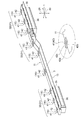
- FIG. 3 is an exploded perspective view of the substrate case of FIG. 2.
- FIG. 3 is a perspective view of the inner case of FIG. 2.
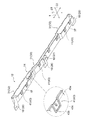
- FIG. 3 is a perspective view of the outer case of FIG. 2. It is sectional drawing of the board
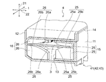
- FIG. 4 is a partially enlarged perspective view of a central position defining portion of the outer case of FIG. 3. It is a partial expansion perspective view of the center position prescription
- an instrument panel is installed in the front of the passenger compartment.
- a vehicle body strength member 2 extending in the vehicle width direction 1 is installed inside the instrument panel.
- substrate is arrange
- this harness substrate is constituted by a long substrate 3 (see FIG. 3) having a length (for example, about 2 m) close to the width dimension of the vehicle.
- two long substrates 3 having a length of about half the width of the vehicle (for example, about 1 m) are connected to each other.
- the long substrate 3 is fixed to the upper portion of the vehicle body strength member 2 together with the substrate case 4 while being accommodated in the substrate case 4.
- the substrate case 4 accommodating the long substrate 3 may be fixed to the lower part, the front part or the rear part of the vehicle body strength member 2.
- the vehicle body strength member 2 described above is called a steering support member or a cross car beam.
- the above-described wire harness is a bundle of electric wires for supplying electric power, signals, and the like to each part of the vehicle body, and the harness substrate is the long substrate 3 in which the wire harness is formed as described above.
- the long substrate 3 is extremely difficult to manufacture and has a large influence of distortion and warpage as compared with a relatively short and small rectangular shape such as a normal substrate.
- the vehicle of this embodiment has the following configuration.
- the long substrate 3 is the harness substrate described above.
- a long substrate 3 is not limited to a harness substrate.
- the long substrate 3 has long side portions (front edge portion and rear edge portion) positioned in the vehicle front-rear direction 22, and both end portions (right end portion and left end portion) positioned in the vehicle width direction 1. Short side.
- the harness board is a long board 3 extending in the vehicle width direction 1 and having a narrow width with respect to the vertical direction 21 with its plate surface (mounting surface) substantially oriented in the vehicle front-rear direction 22. It is also possible. This case is not particularly described in this embodiment, but can be applied by replacing the vertical direction 21 and the vehicle longitudinal direction 22 in the following description.
- the substrate case 4 of this embodiment includes an inner case 11 that can accommodate the long substrate 3 therein and an outer case 12 that can accommodate the inner case 11 together with the long substrate 3.
- the inner case 11 has, on one side, a long substrate insertion opening 13 into which the long substrate 3 can be inserted in a direction parallel to the plate surface of the long substrate 3.
- the outer case 12 has an inner case insertion opening 14 on the other side portion through which the inner case 11 can be inserted in a direction parallel to the plate surface of the long substrate 3.
- a substrate sandwiching portion 15 capable of sandwiching and holding the long substrate 3 in the perpendicular direction is provided in the inner case 11.
- a substrate suppressing portion 16 is provided in the outer case 12 to suppress the fluttering in the direction perpendicular to the surface of the long substrate 3.
- the outer case 12 has an external fixing portion 18 that can be fixed to the mounted member 17.
- the attached member 17 will be described later.
- the above-mentioned “one side portion” becomes the front edge portion (front surface portion) or the rear edge portion (rear surface portion) in the vehicle front-rear direction 22, and the “other side portion” becomes the rear edge portion ( It becomes a rear surface portion) or a front edge portion (front surface portion).
- the above-mentioned “direction parallel to the plate surface of the long substrate 3” is the vehicle front-rear direction 22, and “the direction perpendicular to the surface of the long substrate 3” is the vertical direction 21.
- the “direction parallel to the plate surface of the long substrate 3” includes a vehicle width direction 1 and an intermediate (oblique) direction between the vehicle longitudinal direction 22 and the vehicle width direction 1, but these directions are Since the insertion amount becomes long or the structure becomes complicated, the long substrate 3 and the inner case 11 are preferably inserted in the vehicle front-rear direction 22.
- the above-described “inner case 11” extends slightly longer in the vehicle width direction 1 than the long substrate 3, has an opening serving as a long substrate insertion opening 13 on one side, and has a substrate accommodation space inside.
- the member has a substantially C-shaped cross section in side view.
- the inner arm 11 has a C-shaped cross section (a pair of upper and lower sides) and has a length that is about half the width of the long substrate 3. As a result, a substantially half-width portion of the long substrate 3 is accommodated in the inner case 11.
- end face portions that cover at least a part of the C-shaped cross section can be provided as necessary.
- the “outer case 12” extends slightly longer in the vehicle width direction 1 than the inner case 11, has an opening serving as an inner case insertion port 14 on the other side, and accommodates a substrate accommodating space or an inner case inside.
- the inner case insertion port 14 of the outer case 12 is provided to face the long substrate insertion port 13 of the inner case 11.
- the C-shaped (a pair of upper and lower) horizontal arms of the outer case 12 has a length that can accommodate the entire width of the inner case 11. At both ends of the inner case 11, end face portions that cover at least a part of the C-shaped cross section can be provided as necessary.
- the above-mentioned “long board insertion opening 13” extends in the longitudinal direction of the long board 3 (vehicle width direction 1, the same applies hereinafter).
- the long substrate insertion opening 13 has an interval in the vertical direction 21 that is substantially the same as or slightly wider than the thickness of the long substrate 3 so that the long substrate 3 can be inserted.
- the long substrate insertion opening 13 is the sum of the thickness of the long substrate 3 and the height dimension of the substrate sandwiching portion 15.
- the space in the up-down direction 21 is wide by an amount corresponding to.
- the “inner case insertion opening 14” extends in the longitudinal direction of the long substrate 3.
- the inner case insertion opening 14 has an interval (in the vertical direction 21) that is the same as or slightly wider than the thickness of the inner case 11. This interval is such an interval that the inner case 11 can be accommodated with almost no gap.
- the above-described “substrate clamping portion 15” is formed by, for example, a pair of upper and lower press-fitting ribs 25 provided on the inner portion of the inner case 11 having a C-shaped cross section. Composed.
- inclined portions 25 a that are close to each other as they go to the back side are provided at least on the entry side.
- the inclined portion 25a may be linear or (convex) curved.
- parallel portions 25b having an interval substantially equal to or slightly narrower than the plate thickness of the long substrate 3 are provided on the inner side of the press-fitting rib 25 as necessary.
- a plurality of the substrate sandwiching portions 15 are provided along the longitudinal direction of the inner case 11.
- the “substrate restraining portion 16” includes, for example, a pair of (upper and lower) holding ribs 26 provided on the inner portion of the outer case 12 having a C-shaped cross section.
- the portions of the pair of holding ribs 26 that suppress the fluttering of the plate surface of the long substrate 3 are provided with inclined portions 26a that are close to each other as they go to the back side, at least on the entry side.
- the inclined portion 26a may be linear or (convex) curved.
- the back side portion of the holding rib 26 is provided with parallel portions 26b having a slightly wider interval than the above-described parallel portions 25b.
- a plurality of the substrate suppressing portions 16 are provided along the longitudinal direction of the outer case 12.
- the “attached member 17” described above is, for example, the vehicle body strength member 2 described above.
- the substrate case 4 is attached and fixed to the upper part or the lower part (in this case, the upper part) of the vehicle body strength member 2.
- the “external fixing part 18” can be constituted by a pin fixing part 27, a screwing part 28, etc., as shown in the partial enlarged views of FIG. 3 and FIG.
- a pin fixing portion 27 is provided for positioning relative to the central portion of the outer case 12 in the longitudinal direction.
- the pin fixing portion 27 is constituted by a positioning locking pin that extends in a substantially perpendicular direction from the surface (lower surface) of the outer case 12 that contacts the vehicle body strength member 2 toward the vehicle body strength member 2.
- a pin hole (not shown) into which the positioning locking pin is fitted and locked is provided at a corresponding position (a central portion in the longitudinal direction) of the vehicle body strength member 2.
- screw fixing portions 28 are provided for fixing to the center portion and both end portions (three locations) in the longitudinal direction of the outer case 12.
- the screwing portion 28 is configured by an attachment piece having a surface parallel to the long substrate 3 and extending outward from one side portion of the outer case 12.
- the mounting piece is provided with a screw hole for screwing.
- the central screw hole portion is a round hole for position fixing
- the screw hole portions at both ends are long holes extending in the longitudinal direction so as to absorb errors and thermal expansion.
- the above-described substrate sandwiching portion 15 can be provided at an arbitrary position, but is preferably provided at the following position.
- the substrate sandwiching portion 15 is provided at a strain suppression point 31 of the long substrate 3.
- One or a plurality of substrate sandwiching portions 15 can be provided for each distortion suppression point 31.
- the distortion suppression point 31 is the position of the connector mounting portion 32 or the shape changing portion 33 of the long substrate 3.
- the “connector mounting portion 32” is literally a portion where an external connector is mounted on the long substrate 3.
- the long substrate 3 is provided with a connector 35 that can be connected to the external connector on the lower surface side of both end portions.
- the connector mounting portion 32 is not limited to the above, and can be provided at an appropriate position.
- the inner case 11 and the outer case 12 are provided with connector accommodating portions 36 and 37 that can accommodate the connector 35, respectively.
- the connector accommodating portions 36 and 37 have an opening portion for allowing connection of an external connector, and the opening portion is provided toward the vehicle rear side.
- the “shape changing portion 33” is literally a portion where the shape of the long substrate 3 changes.
- the long substrate 3 has an upper and lower step portion as the shape changing portion 33 at a position between the center portion and the end portion.
- This shape change part 33 may be formed according to the shape change part of the upper surface of the to-be-attached member 17, for example.
- a portion where the distance between them becomes long can also be set as the strain suppression point 31 to provide the substrate sandwiching portion 15.
- substrate suppression part 16 in the same position as the board
- substrate suppression part 16 may be provided facing the board
- a case fixing portion 41 is provided between the inner case 11 and the outer case 12 so that both can be fixed at a distortion suppression point 31.
- the “case fixing portion 41” regulates the movement of the inner case 11 in the direction perpendicular to the surface (vertical direction 21) with respect to the outer case 12, and at least slightly moves in the longitudinal direction (vehicle width direction 1). It should be acceptable.
- the case fixing portion 41 described above is an engaging portion including an engaging piece 42 provided on one of the inner case 11 and the outer case 12 and an engaged portion 43 provided on the other.
- the engaging piece 42 and the engaged portion 43 are literally engaged with each other to fix the inner case 11 and the outer case 12.
- the engaging piece 42 is provided on the inner case 11 side and the engaged portion 43 is provided on the outer case 12 side.
- this configuration may be reversed.
- the “engagement piece 42” protrudes from the other side of the inner case 11 toward the upper surface side or the lower surface side.
- the engagement piece 42 has a length substantially equal to the thickness of the inner case insertion port 14 of the outer case 12 and rises substantially in the vertical direction 21, and the upper surface of the outer case 12 from the end of the vertical portion 42 a.
- a parallel portion 42b bent so as to be parallel to each other.
- the parallel portion 42b can be brought into surface contact or pressure contact with the upper surface or the lower surface of the outer case 12.
- the parallel portion 42b may have a trapezoidal shape that is tapered in a plan view so that it can be guided when engaged with the engaged portion 43.
- the “engaged portion 43” is a concave portion that is provided on the upper surface or the lower surface of the other side portion of the outer case 12 and has a shape that substantially matches the engagement piece 42. 43a, or a peripheral wall 43b that surrounds at least a part of the outer periphery of the engagement piece 42.
- the concave portion 43a or the peripheral wall portion 43b has, for example, a trapezoidal shape that is tapered in plan view so that it can substantially match the parallel portion 42b.
- an inner claw portion 43c is provided inside the engaged portion 43 as shown in FIG. 5, and a parallel portion 42b of each engaging piece 42 as shown in FIG.
- a double claw may be formed.
- the case fixing portion 41 is restricted from moving in the direction perpendicular to the inner case 11 with respect to the outer case 12, and at least slightly moved in the longitudinal direction (vehicle width direction 1).
- vehicle width direction 1 there is a gap between the engaging piece 42 and the engaged portion 43 and between the inner claw portion 43c and the inner claw receiving portion 42c with respect to the longitudinal direction.
- Some play gaps 44a and 44b are provided.
- the play gaps 44 a and 44 b may be provided in the vehicle front-rear direction 22 in order to allow slight movement in the vehicle front-rear direction 22.
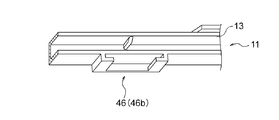
- a central position defining portion 46 capable of defining the position of the central portion in the longitudinal direction is provided.
- the “center position defining portion 46” is provided on the slide guide 46a provided on the upper surface side inside the outer case 12, and on the lower surface side outside the inner case 11 as shown in FIG. And a guide receiver 46b.
- the slide guide 46a and the guide receiver 46b extend in the insertion direction of the inner case 11 with respect to the outer case 12, and are slidably fitted.
- the shapes of the slide guide 46a and the guide receiver 46b are not limited to those illustrated.
- a longitudinal position restricting portion 47 capable of restricting the longitudinal position of the long substrate 3 with respect to the inner case 11 is provided between the inner case 11 and the long substrate 3. Yes.
- the “longitudinal position restricting portions 47” are provided at a pair of longitudinal position restricting claw portions 48 provided at both ends of the inner case 11 or in the vicinity thereof, and at both ends of the long substrate 3 or in the vicinity thereof.
- the above-mentioned “longitudinal position restricting claw portion 48” extends substantially in parallel with the horizontal arm portion from the vertical connecting portion having a C-shaped cross section of the inner case 11.
- the longitudinal position restricting claw portion 48 is engaged with the long substrate 3 from the upper surface side.
- the “longitudinal position restricting claw receiving portion 49” is, for example, one of which is a round hole for position fixing and the other is a long hole or a long hole extending in the longitudinal direction so as to absorb errors and thermal expansion. It is a hole-shaped notch.
- the round hole, the long hole, and the like are provided in the center of the width of the long substrate 3.
- the structure of the substrate case 4 described above can be widely applied to the long substrate 3 other than the harness substrate.
- the long substrate 3 is accommodated in the outer case 12 while being accommodated in the inner case 11.
- the long substrate 3 is inserted from the other side into the long substrate insertion port 13 on one side of the inner case 11 in a direction parallel to the plate surface of the long substrate 3. Further, the inner case 11 containing the long substrate 3 is inserted from one side into the inner case insertion port 14 on the other side of the outer case 12 in a direction parallel to the plate surface of the long substrate 3. .
- the long substrate 3 accommodated in the inner case 11 is held (or crimped) in a direction perpendicular to the surface by a substrate holding portion 15 provided inside the inner case 11. Further, the long substrate 3 accommodated in the outer case 12 together with the inner case 11 is suppressed to the extent that it does not flutter in the perpendicular direction by the substrate suppressing portion 16 provided inside the outer case 12. As described above, by using the inner side of the outer case 12 as the substrate suppressing portion 16, it is possible to suppress the long substrate 3 and make it difficult to transmit influences such as vibration from the outside to the long substrate 3.
- the outer case 12 is fixed to the attached member 17 by the external fixing portion 18.
- the substrate case 4 is divided into one side and the other side (in the case of the vehicle longitudinal direction 22 in this embodiment), and the substrate sandwiching portion 15 and the substrate are separated. Since the long substrate 3 is constrained in the perpendicular direction by the restraining portion 16, the distortion of the long substrate 3 can be effectively suppressed simply by attaching the substrate case 4 to the long substrate 3. In addition, it is not necessary to use a large number of fastening members, and it is not necessary to manage the amount of warping with respect to the long substrate 3 due to the fastening amount of the fastening members during assembly. As a result, it is possible to greatly reduce the assembly man-hours and the part costs.
- the substrate sandwiching portion 15 is provided at the strain suppression point 31 of the long substrate 3, the substrate sandwiching portion 15 can efficiently suppress the strain of the long substrate 3.
- the inner case 11 and the outer case 12 are engaged and fixed by a case fixing portion 41. Then, by providing the case fixing portion 41 at the strain suppression point 31, it is possible to more effectively suppress the distortion of the long substrate 3.
- the engagement piece 42 is provided on one of the inner case 11 and the outer case 12 and the engaged portion 43 is provided on the other, the inner case 11 can be inserted into the outer case 12 with a single touch.
- the outer case 12 can be engaged and fixed easily and reliably.
- the longitudinal position of the long substrate 3 relative to the inner case 11 can be reliably regulated by the longitudinal position restricting portion 47 provided between the inner case 11 and the long substrate 3.
Landscapes
- Engineering & Computer Science (AREA)
- Microelectronics & Electronic Packaging (AREA)
- Mechanical Engineering (AREA)
- Casings For Electric Apparatus (AREA)
- Connection Or Junction Boxes (AREA)
- Mounting Of Printed Circuit Boards And The Like (AREA)
- Connector Housings Or Holding Contact Members (AREA)
Abstract
L'invention concerne une enveloppe de substrat (4) qui est équipée : d'une enveloppe interne (11) capable d'admettre un substrat allongé (3); et d'une enveloppe externe (12) capable d'admettre l'enveloppe interne (11). L'enveloppe interne (11) possède sur une partie d'un côté, une ouverture d'insertion de substrat allongé (13) permettant l'insertion du substrat allongé (3); et l'enveloppe externe (12) possède sur une partie de l'autre côté, une ouverture d'insertion d'enveloppe interne (14) permettant l'insertion de l'enveloppe interne (11). Une partie enserrement de substrat (15) permettant de maintenir par enserrement le substrat allongé (3), est agencée dans la partie intérieure de l'enveloppe interne (11). Une partie retenue de substrat (16) empêchant le mouvement du substrat allongé (3), est agencée dans la partie intérieure de l'enveloppe externe (12). L'enveloppe externe (12) possède une partie fixation de partie externe (18) permettant une fixation sur un élément à installer (17).
Priority Applications (2)
| Application Number | Priority Date | Filing Date | Title |
|---|---|---|---|
| CN201280030645.9A CN103636090A (zh) | 2011-06-22 | 2012-05-31 | 基板壳体结构 |
| US14/125,888 US20140110163A1 (en) | 2011-06-22 | 2012-05-31 | Substrate case structure |
Applications Claiming Priority (2)
| Application Number | Priority Date | Filing Date | Title |
|---|---|---|---|
| JP2011138282A JP2013009446A (ja) | 2011-06-22 | 2011-06-22 | 基板ケース構造 |
| JP2011-138282 | 2011-06-22 |
Publications (1)
| Publication Number | Publication Date |
|---|---|
| WO2012176603A1 true WO2012176603A1 (fr) | 2012-12-27 |
Family
ID=47422443
Family Applications (1)
| Application Number | Title | Priority Date | Filing Date |
|---|---|---|---|
| PCT/JP2012/064140 Ceased WO2012176603A1 (fr) | 2011-06-22 | 2012-05-31 | Structure d'enveloppe de substrat |
Country Status (4)
| Country | Link |
|---|---|
| US (1) | US20140110163A1 (fr) |
| JP (1) | JP2013009446A (fr) |
| CN (1) | CN103636090A (fr) |
| WO (1) | WO2012176603A1 (fr) |
Cited By (1)
| Publication number | Priority date | Publication date | Assignee | Title |
|---|---|---|---|---|
| CN111797468A (zh) * | 2020-06-17 | 2020-10-20 | 江西洪都航空工业集团有限责任公司 | 一种后边条维形框壁板颤振抑制方法 |
Families Citing this family (2)
| Publication number | Priority date | Publication date | Assignee | Title |
|---|---|---|---|---|
| JP6700651B2 (ja) * | 2014-04-03 | 2020-05-27 | 日立オートモティブシステムズ株式会社 | ステレオカメラ装置 |
| FR3037300B1 (fr) * | 2015-06-11 | 2018-07-13 | Renault S.A.S | Dispositif de support de boitiers electroniques |
Citations (7)
| Publication number | Priority date | Publication date | Assignee | Title |
|---|---|---|---|---|
| JPH0418478U (fr) * | 1990-06-05 | 1992-02-17 | ||
| JPH04282896A (ja) * | 1991-03-11 | 1992-10-07 | Fujitsu Ltd | 小形電子装置筐体 |
| JP2000091771A (ja) * | 1998-09-10 | 2000-03-31 | Matsushita Electric Ind Co Ltd | プリント基板の収納棚板装置 |
| JP2000261166A (ja) * | 1999-03-05 | 2000-09-22 | Denso Corp | 制御機器の基板保持装置 |
| JP2006019674A (ja) * | 2004-06-02 | 2006-01-19 | Denso Corp | 電子装置の筐体構造 |
| JP2007209049A (ja) * | 2006-01-30 | 2007-08-16 | Auto Network Gijutsu Kenkyusho:Kk | 電気接続箱 |
| JP2010035256A (ja) * | 2008-07-25 | 2010-02-12 | Calsonic Kansei Corp | 回路基板ユニット |
Family Cites Families (9)
| Publication number | Priority date | Publication date | Assignee | Title |
|---|---|---|---|---|
| US5111362A (en) * | 1990-09-18 | 1992-05-05 | Intel Corporation | Enclosure assembly with two identical covers having modifiable supports for asymmetrically housing a printed circuit board or the like |
| US5373104A (en) * | 1993-07-12 | 1994-12-13 | Delco Electronics Corporation | Control module with integral fastening/locking assembly |
| JP2002330522A (ja) * | 2001-04-27 | 2002-11-15 | Yazaki Corp | 電気接続箱 |
| JP3977609B2 (ja) * | 2001-04-27 | 2007-09-19 | 矢崎総業株式会社 | 電気接続箱 |
| JP3954915B2 (ja) * | 2002-05-29 | 2007-08-08 | 矢崎総業株式会社 | 電気接続箱とその製造方法 |
| US6894891B2 (en) * | 2003-06-30 | 2005-05-17 | Lear Corporation | Smart junction box for automobile |
| JP5026859B2 (ja) * | 2007-05-28 | 2012-09-19 | 矢崎総業株式会社 | 電気接続箱 |
| JP5108402B2 (ja) * | 2007-07-09 | 2012-12-26 | 株式会社オートネットワーク技術研究所 | 電気接続箱 |
| US8908381B2 (en) * | 2010-07-30 | 2014-12-09 | Mitsubishi Electric Corporation | Housing for electronic device unit |
-
2011
- 2011-06-22 JP JP2011138282A patent/JP2013009446A/ja not_active Withdrawn
-
2012
- 2012-05-31 US US14/125,888 patent/US20140110163A1/en not_active Abandoned
- 2012-05-31 WO PCT/JP2012/064140 patent/WO2012176603A1/fr not_active Ceased
- 2012-05-31 CN CN201280030645.9A patent/CN103636090A/zh active Pending
Patent Citations (7)
| Publication number | Priority date | Publication date | Assignee | Title |
|---|---|---|---|---|
| JPH0418478U (fr) * | 1990-06-05 | 1992-02-17 | ||
| JPH04282896A (ja) * | 1991-03-11 | 1992-10-07 | Fujitsu Ltd | 小形電子装置筐体 |
| JP2000091771A (ja) * | 1998-09-10 | 2000-03-31 | Matsushita Electric Ind Co Ltd | プリント基板の収納棚板装置 |
| JP2000261166A (ja) * | 1999-03-05 | 2000-09-22 | Denso Corp | 制御機器の基板保持装置 |
| JP2006019674A (ja) * | 2004-06-02 | 2006-01-19 | Denso Corp | 電子装置の筐体構造 |
| JP2007209049A (ja) * | 2006-01-30 | 2007-08-16 | Auto Network Gijutsu Kenkyusho:Kk | 電気接続箱 |
| JP2010035256A (ja) * | 2008-07-25 | 2010-02-12 | Calsonic Kansei Corp | 回路基板ユニット |
Cited By (1)
| Publication number | Priority date | Publication date | Assignee | Title |
|---|---|---|---|---|
| CN111797468A (zh) * | 2020-06-17 | 2020-10-20 | 江西洪都航空工业集团有限责任公司 | 一种后边条维形框壁板颤振抑制方法 |
Also Published As
| Publication number | Publication date |
|---|---|
| CN103636090A (zh) | 2014-03-12 |
| JP2013009446A (ja) | 2013-01-10 |
| US20140110163A1 (en) | 2014-04-24 |
Similar Documents
| Publication | Publication Date | Title |
|---|---|---|
| JP2013247046A (ja) | 端子保護カバーおよび電気接続箱 | |
| WO2010131647A1 (fr) | Structure de patte de fixation de boîte de raccordement électrique | |
| JP2008282950A (ja) | 回路基板固定構造 | |
| WO2012176603A1 (fr) | Structure d'enveloppe de substrat | |
| JP2011223650A (ja) | ハーネスプロテクタの固定構造 | |
| KR200496491Y1 (ko) | 차량용 내비게이션 장착을 위한 결합 구조 | |
| KR101234175B1 (ko) | 자체 정렬 연결구 | |
| JP2010132242A (ja) | 自動車のドア用トリムボード及び自動車のバックドア | |
| JP2014125093A (ja) | 樹脂爪構造 | |
| JP4605112B2 (ja) | 電気接続箱 | |
| CN109565162B (zh) | 车载部件 | |
| JP2009149226A (ja) | ヘッドランプ取付構造 | |
| JP5516161B2 (ja) | スタッドボルト用固定機構 | |
| JP2014126127A (ja) | 樹脂爪構造 | |
| JP4219853B2 (ja) | 電気接続箱 | |
| JP7824336B2 (ja) | 導電体 | |
| US10286858B2 (en) | Protective case for electric wires, and sliding seat | |
| JP5606050B2 (ja) | 自動車のオーディオ取付け構造 | |
| WO2017002191A1 (fr) | Console d'unité de commande électronique et véhicule | |
| CN222995797U (zh) | 天线组件和车辆 | |
| JP7448094B1 (ja) | 固定構造 | |
| JP4704967B2 (ja) | ハーネス収容ケースの取付構造 | |
| JP5845086B2 (ja) | 電子装置 | |
| JP7390206B2 (ja) | ルーフライニングの仮保持構造及び仮保持部材 | |
| WO2017188289A1 (fr) | Support, et unité formée par montage d'un boîtier sur le support |
Legal Events
| Date | Code | Title | Description |
|---|---|---|---|
| 121 | Ep: the epo has been informed by wipo that ep was designated in this application |
Ref document number: 12802605 Country of ref document: EP Kind code of ref document: A1 |
|
| WWE | Wipo information: entry into national phase |
Ref document number: 14125888 Country of ref document: US |
|
| NENP | Non-entry into the national phase |
Ref country code: DE |
|
| 122 | Ep: pct application non-entry in european phase |
Ref document number: 12802605 Country of ref document: EP Kind code of ref document: A1 |