WO2012176626A1 - Appareil de placage, procédé de placage et support de stockage - Google Patents
Appareil de placage, procédé de placage et support de stockage Download PDFInfo
- Publication number
- WO2012176626A1 WO2012176626A1 PCT/JP2012/064706 JP2012064706W WO2012176626A1 WO 2012176626 A1 WO2012176626 A1 WO 2012176626A1 JP 2012064706 W JP2012064706 W JP 2012064706W WO 2012176626 A1 WO2012176626 A1 WO 2012176626A1
- Authority
- WO
- WIPO (PCT)
- Prior art keywords
- plating solution
- plating
- substrate
- supply
- tank
- Prior art date
- Legal status (The legal status is an assumption and is not a legal conclusion. Google has not performed a legal analysis and makes no representation as to the accuracy of the status listed.)
- Ceased
Links
Images




Classifications
-
- B—PERFORMING OPERATIONS; TRANSPORTING
- B05—SPRAYING OR ATOMISING IN GENERAL; APPLYING FLUENT MATERIALS TO SURFACES, IN GENERAL
- B05C—APPARATUS FOR APPLYING FLUENT MATERIALS TO SURFACES, IN GENERAL
- B05C11/00—Component parts, details or accessories not specifically provided for in groups B05C1/00 - B05C9/00
- B05C11/10—Storage, supply or control of liquid or other fluent material; Recovery of excess liquid or other fluent material
- B05C11/1039—Recovery of excess liquid or other fluent material; Controlling means therefor
-
- C—CHEMISTRY; METALLURGY
- C23—COATING METALLIC MATERIAL; COATING MATERIAL WITH METALLIC MATERIAL; CHEMICAL SURFACE TREATMENT; DIFFUSION TREATMENT OF METALLIC MATERIAL; COATING BY VACUUM EVAPORATION, BY SPUTTERING, BY ION IMPLANTATION OR BY CHEMICAL VAPOUR DEPOSITION, IN GENERAL; INHIBITING CORROSION OF METALLIC MATERIAL OR INCRUSTATION IN GENERAL
- C23C—COATING METALLIC MATERIAL; COATING MATERIAL WITH METALLIC MATERIAL; SURFACE TREATMENT OF METALLIC MATERIAL BY DIFFUSION INTO THE SURFACE, BY CHEMICAL CONVERSION OR SUBSTITUTION; COATING BY VACUUM EVAPORATION, BY SPUTTERING, BY ION IMPLANTATION OR BY CHEMICAL VAPOUR DEPOSITION, IN GENERAL
- C23C18/00—Chemical coating by decomposition of either liquid compounds or solutions of the coating forming compounds, without leaving reaction products of surface material in the coating; Contact plating
- C23C18/16—Chemical coating by decomposition of either liquid compounds or solutions of the coating forming compounds, without leaving reaction products of surface material in the coating; Contact plating by reduction or substitution, e.g. electroless plating
- C23C18/31—Coating with metals
-
- C—CHEMISTRY; METALLURGY
- C23—COATING METALLIC MATERIAL; COATING MATERIAL WITH METALLIC MATERIAL; CHEMICAL SURFACE TREATMENT; DIFFUSION TREATMENT OF METALLIC MATERIAL; COATING BY VACUUM EVAPORATION, BY SPUTTERING, BY ION IMPLANTATION OR BY CHEMICAL VAPOUR DEPOSITION, IN GENERAL; INHIBITING CORROSION OF METALLIC MATERIAL OR INCRUSTATION IN GENERAL
- C23C—COATING METALLIC MATERIAL; COATING MATERIAL WITH METALLIC MATERIAL; SURFACE TREATMENT OF METALLIC MATERIAL BY DIFFUSION INTO THE SURFACE, BY CHEMICAL CONVERSION OR SUBSTITUTION; COATING BY VACUUM EVAPORATION, BY SPUTTERING, BY ION IMPLANTATION OR BY CHEMICAL VAPOUR DEPOSITION, IN GENERAL
- C23C18/00—Chemical coating by decomposition of either liquid compounds or solutions of the coating forming compounds, without leaving reaction products of surface material in the coating; Contact plating
- C23C18/16—Chemical coating by decomposition of either liquid compounds or solutions of the coating forming compounds, without leaving reaction products of surface material in the coating; Contact plating by reduction or substitution, e.g. electroless plating
- C23C18/1601—Process or apparatus
- C23C18/1619—Apparatus for electroless plating
-
- C—CHEMISTRY; METALLURGY
- C23—COATING METALLIC MATERIAL; COATING MATERIAL WITH METALLIC MATERIAL; CHEMICAL SURFACE TREATMENT; DIFFUSION TREATMENT OF METALLIC MATERIAL; COATING BY VACUUM EVAPORATION, BY SPUTTERING, BY ION IMPLANTATION OR BY CHEMICAL VAPOUR DEPOSITION, IN GENERAL; INHIBITING CORROSION OF METALLIC MATERIAL OR INCRUSTATION IN GENERAL
- C23C—COATING METALLIC MATERIAL; COATING MATERIAL WITH METALLIC MATERIAL; SURFACE TREATMENT OF METALLIC MATERIAL BY DIFFUSION INTO THE SURFACE, BY CHEMICAL CONVERSION OR SUBSTITUTION; COATING BY VACUUM EVAPORATION, BY SPUTTERING, BY ION IMPLANTATION OR BY CHEMICAL VAPOUR DEPOSITION, IN GENERAL
- C23C18/00—Chemical coating by decomposition of either liquid compounds or solutions of the coating forming compounds, without leaving reaction products of surface material in the coating; Contact plating
- C23C18/16—Chemical coating by decomposition of either liquid compounds or solutions of the coating forming compounds, without leaving reaction products of surface material in the coating; Contact plating by reduction or substitution, e.g. electroless plating
-
- C—CHEMISTRY; METALLURGY
- C23—COATING METALLIC MATERIAL; COATING MATERIAL WITH METALLIC MATERIAL; CHEMICAL SURFACE TREATMENT; DIFFUSION TREATMENT OF METALLIC MATERIAL; COATING BY VACUUM EVAPORATION, BY SPUTTERING, BY ION IMPLANTATION OR BY CHEMICAL VAPOUR DEPOSITION, IN GENERAL; INHIBITING CORROSION OF METALLIC MATERIAL OR INCRUSTATION IN GENERAL
- C23C—COATING METALLIC MATERIAL; COATING MATERIAL WITH METALLIC MATERIAL; SURFACE TREATMENT OF METALLIC MATERIAL BY DIFFUSION INTO THE SURFACE, BY CHEMICAL CONVERSION OR SUBSTITUTION; COATING BY VACUUM EVAPORATION, BY SPUTTERING, BY ION IMPLANTATION OR BY CHEMICAL VAPOUR DEPOSITION, IN GENERAL
- C23C18/00—Chemical coating by decomposition of either liquid compounds or solutions of the coating forming compounds, without leaving reaction products of surface material in the coating; Contact plating
- C23C18/16—Chemical coating by decomposition of either liquid compounds or solutions of the coating forming compounds, without leaving reaction products of surface material in the coating; Contact plating by reduction or substitution, e.g. electroless plating
- C23C18/1601—Process or apparatus
- C23C18/1633—Process of electroless plating
- C23C18/1675—Process conditions
- C23C18/168—Control of temperature, e.g. temperature of bath, substrate
-
- C—CHEMISTRY; METALLURGY
- C23—COATING METALLIC MATERIAL; COATING MATERIAL WITH METALLIC MATERIAL; CHEMICAL SURFACE TREATMENT; DIFFUSION TREATMENT OF METALLIC MATERIAL; COATING BY VACUUM EVAPORATION, BY SPUTTERING, BY ION IMPLANTATION OR BY CHEMICAL VAPOUR DEPOSITION, IN GENERAL; INHIBITING CORROSION OF METALLIC MATERIAL OR INCRUSTATION IN GENERAL
- C23C—COATING METALLIC MATERIAL; COATING MATERIAL WITH METALLIC MATERIAL; SURFACE TREATMENT OF METALLIC MATERIAL BY DIFFUSION INTO THE SURFACE, BY CHEMICAL CONVERSION OR SUBSTITUTION; COATING BY VACUUM EVAPORATION, BY SPUTTERING, BY ION IMPLANTATION OR BY CHEMICAL VAPOUR DEPOSITION, IN GENERAL
- C23C18/00—Chemical coating by decomposition of either liquid compounds or solutions of the coating forming compounds, without leaving reaction products of surface material in the coating; Contact plating
- C23C18/16—Chemical coating by decomposition of either liquid compounds or solutions of the coating forming compounds, without leaving reaction products of surface material in the coating; Contact plating by reduction or substitution, e.g. electroless plating
- C23C18/1601—Process or apparatus
- C23C18/1633—Process of electroless plating
- C23C18/1675—Process conditions
- C23C18/1682—Control of atmosphere
-
- C—CHEMISTRY; METALLURGY
- C23—COATING METALLIC MATERIAL; COATING MATERIAL WITH METALLIC MATERIAL; CHEMICAL SURFACE TREATMENT; DIFFUSION TREATMENT OF METALLIC MATERIAL; COATING BY VACUUM EVAPORATION, BY SPUTTERING, BY ION IMPLANTATION OR BY CHEMICAL VAPOUR DEPOSITION, IN GENERAL; INHIBITING CORROSION OF METALLIC MATERIAL OR INCRUSTATION IN GENERAL
- C23C—COATING METALLIC MATERIAL; COATING MATERIAL WITH METALLIC MATERIAL; SURFACE TREATMENT OF METALLIC MATERIAL BY DIFFUSION INTO THE SURFACE, BY CHEMICAL CONVERSION OR SUBSTITUTION; COATING BY VACUUM EVAPORATION, BY SPUTTERING, BY ION IMPLANTATION OR BY CHEMICAL VAPOUR DEPOSITION, IN GENERAL
- C23C18/00—Chemical coating by decomposition of either liquid compounds or solutions of the coating forming compounds, without leaving reaction products of surface material in the coating; Contact plating
- C23C18/16—Chemical coating by decomposition of either liquid compounds or solutions of the coating forming compounds, without leaving reaction products of surface material in the coating; Contact plating by reduction or substitution, e.g. electroless plating
- C23C18/1601—Process or apparatus
- C23C18/1633—Process of electroless plating
- C23C18/1675—Process conditions
- C23C18/1683—Control of electrolyte composition, e.g. measurement, adjustment
-
- C—CHEMISTRY; METALLURGY
- C23—COATING METALLIC MATERIAL; COATING MATERIAL WITH METALLIC MATERIAL; CHEMICAL SURFACE TREATMENT; DIFFUSION TREATMENT OF METALLIC MATERIAL; COATING BY VACUUM EVAPORATION, BY SPUTTERING, BY ION IMPLANTATION OR BY CHEMICAL VAPOUR DEPOSITION, IN GENERAL; INHIBITING CORROSION OF METALLIC MATERIAL OR INCRUSTATION IN GENERAL
- C23C—COATING METALLIC MATERIAL; COATING MATERIAL WITH METALLIC MATERIAL; SURFACE TREATMENT OF METALLIC MATERIAL BY DIFFUSION INTO THE SURFACE, BY CHEMICAL CONVERSION OR SUBSTITUTION; COATING BY VACUUM EVAPORATION, BY SPUTTERING, BY ION IMPLANTATION OR BY CHEMICAL VAPOUR DEPOSITION, IN GENERAL
- C23C18/00—Chemical coating by decomposition of either liquid compounds or solutions of the coating forming compounds, without leaving reaction products of surface material in the coating; Contact plating
- C23C18/16—Chemical coating by decomposition of either liquid compounds or solutions of the coating forming compounds, without leaving reaction products of surface material in the coating; Contact plating by reduction or substitution, e.g. electroless plating
- C23C18/31—Coating with metals
- C23C18/32—Coating with nickel, cobalt or mixtures thereof with phosphorus or boron
-
- C—CHEMISTRY; METALLURGY
- C23—COATING METALLIC MATERIAL; COATING MATERIAL WITH METALLIC MATERIAL; CHEMICAL SURFACE TREATMENT; DIFFUSION TREATMENT OF METALLIC MATERIAL; COATING BY VACUUM EVAPORATION, BY SPUTTERING, BY ION IMPLANTATION OR BY CHEMICAL VAPOUR DEPOSITION, IN GENERAL; INHIBITING CORROSION OF METALLIC MATERIAL OR INCRUSTATION IN GENERAL
- C23C—COATING METALLIC MATERIAL; COATING MATERIAL WITH METALLIC MATERIAL; SURFACE TREATMENT OF METALLIC MATERIAL BY DIFFUSION INTO THE SURFACE, BY CHEMICAL CONVERSION OR SUBSTITUTION; COATING BY VACUUM EVAPORATION, BY SPUTTERING, BY ION IMPLANTATION OR BY CHEMICAL VAPOUR DEPOSITION, IN GENERAL
- C23C18/00—Chemical coating by decomposition of either liquid compounds or solutions of the coating forming compounds, without leaving reaction products of surface material in the coating; Contact plating
- C23C18/16—Chemical coating by decomposition of either liquid compounds or solutions of the coating forming compounds, without leaving reaction products of surface material in the coating; Contact plating by reduction or substitution, e.g. electroless plating
- C23C18/1601—Process or apparatus
- C23C18/1619—Apparatus for electroless plating
- C23C18/1632—Features specific for the apparatus, e.g. layout of cells and of its equipment, multiple cells
-
- C—CHEMISTRY; METALLURGY
- C23—COATING METALLIC MATERIAL; COATING MATERIAL WITH METALLIC MATERIAL; CHEMICAL SURFACE TREATMENT; DIFFUSION TREATMENT OF METALLIC MATERIAL; COATING BY VACUUM EVAPORATION, BY SPUTTERING, BY ION IMPLANTATION OR BY CHEMICAL VAPOUR DEPOSITION, IN GENERAL; INHIBITING CORROSION OF METALLIC MATERIAL OR INCRUSTATION IN GENERAL
- C23C—COATING METALLIC MATERIAL; COATING MATERIAL WITH METALLIC MATERIAL; SURFACE TREATMENT OF METALLIC MATERIAL BY DIFFUSION INTO THE SURFACE, BY CHEMICAL CONVERSION OR SUBSTITUTION; COATING BY VACUUM EVAPORATION, BY SPUTTERING, BY ION IMPLANTATION OR BY CHEMICAL VAPOUR DEPOSITION, IN GENERAL
- C23C18/00—Chemical coating by decomposition of either liquid compounds or solutions of the coating forming compounds, without leaving reaction products of surface material in the coating; Contact plating
- C23C18/16—Chemical coating by decomposition of either liquid compounds or solutions of the coating forming compounds, without leaving reaction products of surface material in the coating; Contact plating by reduction or substitution, e.g. electroless plating
- C23C18/1601—Process or apparatus
- C23C18/1633—Process of electroless plating
- C23C18/1646—Characteristics of the product obtained
- C23C18/165—Multilayered product
Definitions
- the present invention relates to a plating apparatus, a plating method, and a storage medium for supplying a plating solution to the surface of a substrate to perform a plating process.
- wirings are formed on a substrate such as a semiconductor wafer or a liquid crystal substrate in order to form a circuit on the surface.
- This wiring is made of a copper material having a low electrical resistance and high reliability instead of an aluminum material.
- copper is more easily oxidized than aluminum, it is desirable to perform plating with a metal having high electromigration resistance in order to prevent oxidation of the copper wiring surface.
- a plating solution containing metal ions of metal plated on the surface of copper wiring generally contains metal ions of metal to be plated and an ammonia component for complexing the metal ions.
- the plating solution is collected and reused to some extent for cost reduction.
- Patent Document 1 an inert gas is introduced into a plating solution storage tank to replace the inside of the tank, thereby preventing deterioration of the plating solution due to carbon dioxide in the atmosphere dissolved in the plating solution.
- the present invention has been made in consideration of such points, and a plating apparatus, a plating method, and a memory capable of reusing a plating solution by maintaining the concentration of the ammonia component in the plating solution.
- the purpose is to provide a medium.
- the present invention provides a plating apparatus for performing a plating process by supplying a plating solution containing at least an ammonia component to a substrate, and a plating solution to the substrate accommodated in the substrate accommodating part and the substrate accommodated in the substrate accommodating part.
- a plating solution supply mechanism for supplying a supply tank for storing a plating solution to be supplied to the substrate, a discharge nozzle for discharging the plating solution to the substrate, and a plating solution in the supply tank to the discharge nozzle
- a plating solution supply mechanism having a plating solution supply pipe to supply; a plating solution discharge mechanism for discharging the plating solution after being supplied to the substrate from the substrate housing portion and sending the plating solution to the supply tank of the plating solution supply mechanism; Ammonia gas reservoir filled with ammonia gas and sealed, and supplying ammonia gas from the ammonia gas reservoir to the supply tank
- a plating apparatus characterized by comprising an ammonia gas pipe.
- the present invention relates to a plating method for performing plating by supplying a plating solution containing at least an ammonia component to a substrate, and a substrate mounting step for arranging the substrate in a substrate housing portion, and supplying the substrate through a discharge nozzle.
- a plating treatment method comprising: a component adjustment step of adjusting a component of the plating solution; and a reuse step of supplying the plating solution with the adjusted component of the plating solution to the discharge nozzle.
- the present invention relates to a storage medium storing a computer program for causing a plating apparatus to execute a plating method, wherein the plating method performs a plating process by supplying a plating solution containing at least an ammonia component to a substrate.
- a method of placing a substrate in a substrate housing portion, a supply step of supplying a plating solution in a supply tank to the substrate via a discharge nozzle, and a plating solution after being supplied to the substrate A recovery step of recovering the substrate from the substrate container through a plating solution discharge mechanism, a component adjustment step of adjusting the components of the plating solution by exposing the recovered plating solution to ammonia gas, and adjusting the components of the plating solution.
- a reuse step of supplying the plating solution to the discharge nozzle is supplying the plating solution to the discharge nozzle.
- the ammonia gas storage unit since the ammonia gas storage unit is connected to the supply tank, it is possible to suppress the ammonia component in the plating solution stored in the supply tank from volatilizing outward. Furthermore, an ammonia component can be dissolved. For this reason, the density
- FIG. 1 is a plan view showing a schematic configuration of a plating system according to the first embodiment of the present invention.
- FIG. 2 is a side view showing the plating apparatus according to the first embodiment of the present invention.
- FIG. 3 is a plan view of the plating apparatus shown in FIG.
- FIG. 4 is a view showing a liquid supply mechanism in the first embodiment of the present invention.
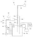
- FIG. 5 is a schematic view showing a plating apparatus according to the first embodiment of the present invention.
- FIG. 6 is a view showing a liquid supply mechanism in the first embodiment of the present invention.
- FIG. 7 is a diagram showing a first heating mechanism in the first embodiment of the present invention.
- FIG. 8 is a diagram showing a second heating mechanism in the first embodiment of the present invention.
- FIG. 9 is a flowchart showing a plating method.
- FIG. 10 is a view showing a plating solution recovery mechanism in the second embodiment of the present invention.
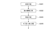
- FIG. 11 is a flowchart showing in detail steps
- the plating system 1 mounts a carrier 3 that accommodates a plurality of substrates 2 (here, 25 semiconductor wafers) (for example, 25 wafers), and carries in a predetermined number of substrates 2. And a substrate loading / unloading chamber 5 for unloading and a substrate processing chamber 6 for performing various processes such as plating and cleaning of the substrate 2.
- the substrate carry-in / out chamber 5 and the substrate processing chamber 6 are provided adjacent to each other.
- the substrate carry-in / out chamber 5 includes a carrier placement unit 4, a transfer chamber 9 that stores the transfer device 8, and a substrate transfer chamber 11 that stores a substrate transfer table 10.
- the transfer chamber 9 and the substrate delivery chamber 11 are connected to each other via a delivery port 12.
- the carrier placement unit 4 places a plurality of carriers 3 that accommodate a plurality of substrates 2 in a horizontal state.
- the substrate 2 is transferred, and in the substrate transfer chamber 11, the substrate 2 is transferred to and from the substrate processing chamber 6.
- a predetermined number of substrates 2 are transported by the transport device 8 between any one carrier 3 placed on the carrier platform 4 and the substrate delivery table 10.
- the substrate processing chamber 6 is arranged in the front and back on one side and the other side of the substrate transfer unit 13 and extends in the front and back in the central portion, and supplies the plating solution to the substrate 2 to perform the plating process.
- a plurality of plating processing apparatuses 20 are arranged in the front and back on one side and the other side of the substrate transfer unit 13 and extends in the front and back in the central portion, and supplies the plating solution to the substrate 2 to perform the plating process.
- a plurality of plating processing apparatuses 20 is arranged in the front and back on one side and the other side of the substrate transfer unit 13 and extends in the front and back in the central portion, and supplies the plating solution to the substrate 2 to perform the plating process.
- the substrate transport unit 13 includes a substrate transport device 14 configured to be movable in the front-rear direction.
- the substrate transfer unit 13 communicates with the substrate transfer table 10 in the substrate transfer chamber 11 via the substrate transfer port 15.
- the substrates 2 are transferred to the respective plating processing apparatuses 20 in a state where the substrates 2 are held horizontally one by one by the substrate transfer device 14 of the substrate transfer unit 13. Then, in each plating processing apparatus 20, the substrate 2 is subjected to cleaning processing and plating processing one by one.
- Each plating apparatus 20 differs only in the plating solution used, and the other points have substantially the same configuration. Therefore, in the following description, the configuration of one plating processing apparatus 20 among the plurality of plating processing apparatuses 20 will be described.
- FIG. 2 is a side view showing the plating apparatus 20
- FIG. 3 is a plan view showing the plating apparatus 20.
- the plating apparatus 20 includes a substrate rotation holding mechanism (substrate housing portion) 110 for rotating and holding the substrate 2 inside the casing 101, and a plating solution and a cleaning solution on the surface of the substrate 2.
- Liquid supply mechanisms 30, 30 ⁇ / b> A, 90, 90 ⁇ / b> A that supply the liquid, a cup 105 that receives the plating liquid and the cleaning liquid scattered from the substrate 2, and discharge ports 124 and 129 that discharge the plating liquid and the cleaning liquid received by the cup 105.
- liquid discharge mechanisms 120, 125, 130 for discharging the liquid collected at the discharge port, substrate rotation holding mechanism 110, liquid supply mechanisms 30, 30A, 90, 90A, cup 105, and liquid discharge mechanisms 120, 125 , 130 is controlled.
- the substrate rotation holding mechanism 110 includes a hollow cylindrical rotation shaft 111 extending vertically in the casing 101, and a turntable 112 attached to the upper end portion of the rotation shaft 111. And a wafer chuck 113 that is provided on the outer peripheral portion of the upper surface of the turntable 112 and supports the substrate 2, and a rotation mechanism 162 that rotates the rotation shaft 111.
- the rotation mechanism 162 is controlled by the control mechanism 160, and the rotation shaft 111 is rotationally driven by the rotation mechanism 162, whereby the substrate 2 supported by the wafer chuck 113 is rotated.
- the liquid supply mechanisms 30, 30A, 90, and 90A for supplying a plating solution and a cleaning solution to the surface of the substrate 2 will be described with reference to FIGS.
- the liquid supply mechanisms 30, 30 ⁇ / b> A, 90, and 90 ⁇ / b> A supply a plating liquid supply mechanism 30 that supplies a plating liquid for performing plating on the surface of the substrate 2, and supplies a cleaning processing liquid for post-cleaning to the surface of the substrate 2.
- a processing liquid supply mechanism 90A for supplying a plating solution for performing pretreatment plating to the surface of substrate 2
- the plating solution supply mechanism 30 supplies a plating solution containing an Ni component and an ammonia component for complexing metal ions, or a plating solution containing an ammonia component for complexing Co metal ions and metal ions. .
- a plating solution containing Pd metal ions is supplied from the pretreatment plating solution supply mechanism 30A.
- FIG. 5 is a schematic diagram showing only the plating solution supply mechanism 30 extracted.
- the pretreatment plating solution supply mechanism 30A and the cleaning treatment solution supply mechanisms 90, 90A are omitted for convenience.
- the plating solution supply mechanism 30 discharges the plating solution 35 to the substrate 2 and a sealed supply tank 31 that stores the plating solution 35 supplied to the substrate 2 at a predetermined temperature. And a plating solution supply pipe 33 for supplying the plating solution 35 in the supply tank 31 to the discharge nozzle 32. As shown in FIG. 4, an openable / closable valve 37 b is inserted in the plating solution supply pipe 33.
- the “predetermined temperature” of the plating solution 35 supplied to the substrate 2 is a temperature equal to or higher than the plating temperature at which the self-reaction proceeds in the plating solution 35. It has become.
- the plating temperature will be described later.
- Various liquids are supplied to the supply tank 31 via a replenishing means 31a from a plurality of supply sources in which various components of the plating solution 35 such as Ni are stored.
- liquids such as NiP metal salts containing Ni ions, reducing agents, additives, aqueous ammonia and pure water are supplied.
- 4 and 5 show only the ammonia water supply unit 174A for replenishing the supply tank 31 with ammonia water and the pure water supply unit 174B for replenishing the supply tank 31 with pure water.
- the supply tank 31 is provided with monitor means 57 for monitoring the characteristics of the plating solution 35.
- This monitoring means 57 has the functions of an ammonia concentration meter, a pH meter, and a thermometer that measure the ammonia concentration of the plating solution 35.
- the flow rate of various liquids supplied to the supply tank 31 by the control mechanism 160 based on the signal from the monitor means 57 is adjusted so that the components of the plating solution 35 stored in the supply tank 31 are appropriately adjusted. It has been adjusted.
- the control mechanism 160 replenishes the supply tank 31 with ammonia water from the ammonia water supply unit 174A or replenishes the supply tank 31 with pure water from the pure water supply unit 174B based on the signal from the monitor unit 57.
- the ammonia component and pH in the plating solution 35 stored in the supply tank 31 are adjusted.
- the supply tank 31 of the plating solution supply mechanism 30 is a hermetically sealed type, and an ammonia gas storage unit 170 is connected to the supply tank 31 by a connecting pipe 176.
- the ammonia gas storage unit 170 has a structure in which ammonia water is stored and can be sealed to change its volume, and is filled with ammonia gas.
- the ammonia gas storage unit 170 supplies ammonia gas to the space above the surface of the plating solution 35 in the supply tank 31. Since the ammonia gas storage unit 170 has a structure capable of changing the volume, the ammonia gas storage unit 170 can maintain an equilibrium state with the pressure of the space on the surface of the plating solution 35. Even if the storage amount of the plating solution in the supply tank 31 changes and the volume of the space on the surface of the plating solution 35 changes, an appropriate amount of ammonia gas can be supplied following the change.
- the plating solution 35 stored in the supply tank 31 can always be exposed to the ammonia gas, the concentration of the ammonia component in the plating solution can be maintained within a predetermined target concentration range, and the plating solution is deteriorated. Can be prevented. For this reason, the plating solution 35 recovered from the substrate accommodating portion 110 to the supply tank 31 of the plating solution supply mechanism 30 via the solution discharge mechanism 120 described later is supplied again from the discharge nozzle 32 to the substrate 2, and thus Thus, the plating solution 35 can be reused a plurality of times.
- the discharge nozzle 32 is attached to the nozzle head 104.
- the nozzle head 104 is attached to the tip of an arm 103.
- the arm 103 can be extended in the vertical direction and is fixed to a support shaft 102 that is rotationally driven by a rotation mechanism 165.
- the plating solution supply pipe 33 of the plating solution supply mechanism 30 is disposed inside the arm 103. With such a configuration, the plating solution can be discharged from a desired height to any location on the surface of the substrate 2 via the discharge nozzle 32.
- a first heating mechanism 50 for heating the plating solution 35 to the first temperature is attached to at least one of the supply tank 31 and the plating solution supply pipe 33 of the plating solution supply mechanism 30.
- a second heating mechanism 60 that heats the plating solution 35 to a second temperature higher than the first temperature is attached to the plating solution supply pipe 33 on the discharge nozzle 32 side of the first heating mechanism 50. The first heating mechanism 50 and the second heating mechanism 60 will be described in detail later.
- a replenishment tank 172 is connected to the supply tank 31.
- An unused plating solution 35 is stored in the replenishing tank 172, and the unused plating solution 35 is supplied into the supply tank 31 to replenish the plating solution consumed by the plating process.
- the ammonia gas storage unit 170 is also connected to the replenishing tank 172, and the plating solution 35 stored in the replenishing tank 172 is always exposed to the ammonia gas. As a result, the concentration of the ammonia component in the plating solution 35 stored in the replenishing tank 172 is maintained within the target concentration range.
- the pretreatment plating solution supply mechanism 30A As shown in FIG. 6, the pretreatment plating solution supply mechanism 30 ⁇ / b> A supplies a plating solution for performing pretreatment plating on the substrate 2.
- the components for supplying the plating solution to the discharge nozzle 32 are different only in the plating solution 35A used, and the other components are the components in the plating solution supply mechanism 30. It is almost the same as the component.
- the discharge nozzle 32 that discharges a plating solution containing Pd onto the surface of the substrate 2 is attached to the nozzle head 109.
- the nozzle head 109 is attached to the tip of the arm 108, and the arm 108 can be extended in the vertical direction and is fixed to the support shaft 107 that is rotationally driven by the rotation mechanism 163. With such a configuration, the plating solution can be discharged from a desired height to any location on the surface of the substrate 2 via the discharge nozzle 32.
- the same parts as those of the plating solution supply mechanism 30 are denoted by the same reference numerals, and detailed description thereof is omitted.
- the cleaning processing liquid supply mechanism 90 is used in the post-cleaning step of the substrate 2 and includes a nozzle 92 attached to the nozzle head 104 as shown in FIG.
- the cleaning processing liquid supply mechanism 90 includes a tank 91 that stores the cleaning processing liquid 93 supplied to the substrate 2, and a supply pipe 94 that supplies the cleaning processing liquid 93 in the tank 91 to the nozzle 92. And a pump 96 and a valve 97a inserted in the supply pipe 94. As shown in FIG.
- the supply pipe 94 and the nozzle 92 are shared with a rinse process liquid supply mechanism 95 that supplies a rinse process liquid such as pure water to the surface of the substrate 2. May be.
- a rinse process liquid supply mechanism 95 that supplies a rinse process liquid such as pure water to the surface of the substrate 2.
- the cleaning liquid supply mechanism 90A is used in a pre-cleaning step of the substrate 2 and includes a nozzle 92 attached to the nozzle head 109 as shown in FIG.
- the components of the cleaning process liquid supply mechanism 90A differ only in the cleaning process liquid 93A used, and the other components are substantially the same as those of the cleaning process liquid supply mechanism 90. ing.
- the cleaning processing liquid supply mechanism 90A shown in FIG. 6 the same parts as those in the cleaning processing liquid supply mechanism 90 are denoted by the same reference numerals, and detailed description thereof is omitted.
- liquid discharge mechanism 120, 125, and 130 for discharging the plating solution and the cleaning solution scattered from the substrate 2 will be described with reference to FIG.
- a cup 105 that is driven up and down by an elevating mechanism 164 and has outlets 124, 129, and 134 is disposed in the casing 101.
- the liquid discharge mechanisms 120, 125, and 130 discharge the liquid collected at the discharge ports 124, 129, and 134, respectively.
- the treatment liquid supplied to the substrate 2 can be discharged by the liquid discharge mechanism 120, 125, 130 via the discharge ports 124, 129, 134 for each type.
- the liquid discharge mechanism 120 is the plating liquid discharge mechanism 120 that discharges the plating liquid 35
- the liquid discharge mechanism 125 is the plating liquid discharge mechanism 125 that discharges the plating liquid 35 ⁇ / b> A
- the liquid discharge mechanism 130 Is a treatment liquid discharge mechanism 130 for discharging the cleaning treatment liquids 93, 93A and the rinse treatment liquid.
- the plating solution discharge mechanisms 120 and 125 have recovery flow paths 122 and 127 and discard flow paths 123 and 128 that are switched by flow path switches 121 and 126, respectively.
- the recovery channels 122 and 127 are channels for recovering and reusing the plating solution
- the discard channels 123 and 128 are channels for discarding the plating solution.
- the treatment liquid discharge mechanism 130 is provided with only the waste flow path 133.
- a recovery channel 122 of a plating solution discharge mechanism 120 that discharges the plating solution 35 is connected to the outlet side of the substrate storage unit 110.
- a cooling buffer 120 ⁇ / b> A for cooling the plating solution 35 is provided in the vicinity of the outlet side of the portion 110. Then, the plating solution 35 cooled by the cooling buffer 120A is returned to the supply tank 31 through the recovery flow path 122.
- FIG. 7 shows a first heating mechanism 50 having a supply tank circulation heating means 51 for heating the plating solution 35 to a first temperature.
- the first temperature is a predetermined temperature that is lower than the temperature (plating temperature) at which the deposition of metal ions due to self-reaction in the plating solution 35 proceeds and higher than room temperature.
- the plating temperature is about 60 degrees, and in this case, the first temperature is set within a range of 40 to 60 degrees.
- the supply tank circulation heating means 51 is attached to the supply tank circulation pipe 52 for circulating the plating solution 35 in the vicinity of the supply tank 31, and the supply tank circulation pipe 52. And a supply tank heater 53 for heating to a first temperature. As shown in FIG. 7, a pump 56 for circulating the plating solution 35 and a filter 55 are interposed in the supply tank circulation pipe 52. By providing such a supply tank circulation heating means 51, the plating solution 35 in the supply tank 31 can be heated to the first temperature while circulating in the vicinity of the supply tank 31. Further, as shown in FIG. 7, a plating solution supply pipe 33 is connected to the supply tank circulation pipe 52. In this case, when the valve 37 a shown in FIG.
- the supply tank circulation pipe 52 is provided with monitoring means 57 for monitoring the characteristics of the plating solution 35, as shown by a one-dot chain line in FIG. May be.
- the second heating mechanism 60 is for heating the plating solution 35 heated to the first temperature by the first heating mechanism 50 to the second temperature.
- the second temperature is a predetermined temperature that is equal to or higher than the plating temperature described above.
- the plating temperature is about 60 degrees as described above, and in this case, the second temperature is set within the range of 60 to 90 degrees.
- the second heating mechanism 60 includes a second temperature medium supply unit 61 that heats a predetermined heat transfer medium to a second temperature or a temperature higher than the second temperature, and the first heating mechanism 50.
- a temperature controller 62 attached to the plating solution supply pipe 33 on the discharge nozzle 32 side and configured to conduct heat of the heat transfer medium from the second temperature medium supply means 61 to the plating solution 35 in the plating solution supply pipe 33. is doing. Further, as shown in FIG. 8, even if a temperature holder 65 is further provided for holding the plating solution 35 provided at the arm 103 and passing through the plating solution supply pipe 33 located in the arm 103 at the second temperature. Good. In FIG.
- the plating solution supply pipe located in the temperature controller 62 is denoted by reference numeral 33a, and the plating solution supply pipe located in the temperature holder 65 (in the arm 103) is shown. It is represented by reference numeral 33b.
- the temperature controller 62 has a supply port 62a for introducing a heat transfer medium for temperature adjustment (for example, hot water) supplied from the second temperature medium supply means 61, and a discharge port 62b for discharging the heat transfer medium. ing.
- the heat transfer medium supplied from the supply port 62 a contacts the plating solution supply pipe 33 a while flowing through the space 62 c inside the temperature controller 62. As a result, the plating solution 35 flowing through the plating solution supply pipe 33a is heated to the second temperature.
- the heat transfer medium after being used for heating the plating solution 35 is discharged from the discharge port 62b.
- the temperature holder 65 disposed between the temperature controller 62 and the discharge nozzle 32 is a plating heated to the second temperature by the temperature controller 62 until the plating solution 35 is discharged from the discharge nozzle 32. This is for maintaining the temperature of the liquid 35.
- the temperature holder 65 includes a heat retaining pipe 65 c extending in contact with the plating solution supply pipe 33 b in the temperature holder 65 and a heat transfer medium supplied from the second temperature medium supply means 61. It has the supply port 65a introduced into the heat insulation pipe 65c, and the discharge port 65b which discharges
- the heat retaining pipe 65c extends to the immediate vicinity of the discharge nozzle 32 along the plating solution supply pipe 33b, whereby the temperature of the plating solution 35 immediately before being discharged from the discharge nozzle 32 can be maintained at the second temperature. .
- the heat retaining pipe 65 c may be opened inside the nozzle head 104 that houses the discharge nozzle 32 and may communicate with a space 65 d in the temperature retainer 65.
- the temperature holder 65 includes the plating solution supply pipe 33b located at the center of the cross section, the heat retaining pipe 65c disposed in thermal contact with the outer periphery of the plating solution supply pipe 33b, and the outer periphery of the heat retaining pipe 65c. It has a triple structure (structure of triple piping) consisting of a space 65d located in the area.
- the heat transfer medium supplied from the supply port 65 a keeps the plating solution 35 through the heat insulation pipe 65 c until reaching the nozzle head 104, and then is discharged from the discharge port 65 b through the space 65 d in the temperature holder 65.
- the plating apparatus 20 further includes a back surface treatment liquid supply mechanism 145 that supplies a treatment liquid to the back surface of the substrate 2 and a back surface gas supply mechanism 150 that supplies gas to the back surface of the substrate 2. You may do it.
- the plating processing system 1 including a plurality of plating processing apparatuses 20 configured as described above is driven and controlled by the control mechanism 160 according to various programs recorded in the storage medium 161 provided in the control mechanism 160, whereby the substrate 2 is controlled. Various processes are performed.
- the storage medium 161 stores various setting data and various programs such as a plating processing program described later.
- known media such as a computer-readable memory such as ROM and RAM, and a disk-shaped storage medium such as a hard disk, CD-ROM, DVD-ROM, and flexible disk can be used.
- the plating processing system 1 and the plating processing apparatus 20 are driven and controlled to perform plating processing on the substrate 2 in accordance with the plating processing program recorded in the storage medium 161.
- a plating solution containing Ni ions is used as the plating solution 35 for plating treatment
- a plating solution containing Pd ions is used as the plating solution 35A for pretreatment plating.
- Temperature control method for chemical reduction plating solution A process of adjusting the temperature of the plating solution 35 discharged onto the surface of the substrate 2 will be described. First, referring to FIG. 7, the temperature of the plating solution 35 discharged to the surface of the substrate 2 is heated to a first temperature lower than a predetermined temperature when the plating process is performed by being supplied to the substrate 2. 1 temperature adjustment process is demonstrated. First, the temperature of the supply tank heater 53 of the first heating mechanism 50 is raised to the first temperature or a temperature higher than the first temperature. Next, by using the pump 56, the plating solution 35 is heated to the first temperature while being circulated in the supply tank circulation pipe 52. At this time, the valve 37a is opened and the valve 37b is closed. Thereby, the temperature of the plating solution 35 stored in the supply tank 31 is controlled to the first temperature.
- the temperature of the plating solution 35 is heated to a second temperature equal to or higher than a predetermined temperature when the plating process is performed by being supplied to the substrate 2.
- the valve 37a is closed and the valve 37b is opened.
- the plating solution 35 controlled to the first temperature is sent to the temperature regulator 62 of the second heating mechanism 60 through the plating solution supply pipe 33.
- a heat transfer medium heated to a second temperature or a temperature higher than the second temperature is supplied from the second temperature medium supply means 61 to the temperature controller 62. For this reason, the plating solution 35 is heated to the second temperature while passing through the plating solution supply pipe 33 a inside the temperature controller 62.
- the plating solution 35 heated to the second temperature is sent to the discharge nozzle 32 via the arm 103 as shown in FIG.
- the arm 103 is provided with a temperature holder 65, and a heat transfer medium heated to the second temperature is supplied from the second temperature medium supply means 61 to the temperature holder 65. For this reason, the plating solution 35 is held at the second temperature until it reaches the discharge nozzle 32 through the plating solution supply pipe 33 b inside the temperature holder 65.
- Pd plating is applied to the substrate 2 by displacement plating (pretreatment plating) using one plating apparatus 20 and then Ni plating is performed using the Ni plating solution prepared as described above.
- a method of applying a chemical reduction plating (plating treatment) will be described with reference to FIG.
- a substrate carrying-in process and a substrate receiving process are performed.
- the cup 105 is lowered to a predetermined position, and then the loaded substrate 2 is supported by the wafer chuck 113, and then the discharge port 134 and the outer peripheral edge of the substrate 2 face each other.
- the cup 105 is raised by the elevating mechanism 164 to the position.
- a pre-cleaning process including a rinse process, a pre-clean process, and a subsequent rinse process is executed (S302).
- the valve 97b of the rinsing process liquid supply mechanism 95A is opened, whereby the rinsing process liquid is supplied to the surface of the substrate 2 through the nozzle 92.
- a pre-cleaning process is performed.
- the valve 97b of the rinsing process liquid supply mechanism 95A is closed and the valve 97a of the cleaning process liquid supply mechanism 90A is opened, whereby the cleaning process liquid 93A is supplied to the surface of the substrate 2 via the nozzle 92.
- the rinsing process liquid is supplied to the surface of the substrate 2 through the nozzle 92, and the rinsing process is performed.
- the rinse treatment liquid and the cleaning treatment liquid 93A after the treatment are discarded through the discharge port 134 of the cup 105 and the waste flow path 133 of the treatment liquid discharge mechanism 130.
- the valve 97b is closed.
- Pd plating process Next, a Pd plating process is executed (execution of a pretreatment plating process) (S303). This Pd plating process is executed as a displacement plating process while the substrate 2 after the pre-cleaning process is not dried.
- the cup 105 is lowered by the elevating mechanism 164 to a position where the discharge port 129 and the outer peripheral edge of the substrate 2 face each other.
- the valve 37b of the plating solution supply mechanism 30A is opened, whereby the plating solution 35A containing Pd stored in the supply tank 31 is discharged onto the surface of the substrate 2 at a desired flow rate via the discharge nozzle 32. Is done.
- Pd plating is performed on the surface of the substrate 2 by displacement plating.
- the treated plating solution 35 ⁇ / b> A is discharged from the discharge port 129 of the cup 105.
- the treated plating solution 35 ⁇ / b> A is recovered in the supply tank 31 via the recovery channel 127 or discarded via the discard channel 128.
- the valve 37b is closed.
- Ni plating process Thereafter, the Ni plating process is executed (execution of the plating process) (S305) in the same plating apparatus 20 where the above-described processes S302 to 304 are executed.
- This Ni plating process is performed as a chemical reduction plating process.
- the cup 105 is lowered by the elevating mechanism 164 to a position where the discharge port 124 and the outer peripheral edge of the substrate 2 face each other.
- the plating solution 35 heated to the first temperature by the first heating mechanism 50 and heated to the second temperature by the second heating mechanism 60 is discharged from the discharge nozzle 32 at a desired flow rate.
- Ni plating is applied to the surface of the substrate 2 by chemical reduction plating.
- the treated plating solution 35 is discharged from the discharge port 124 of the cup 105.
- the discharged plating solution 35 after processing is recovered in the supply tank 31 via the recovery channel 122 or discarded via the discard channel 123.
- the treated plating solution 35 discharged from the discharge port 124 is smaller than the discharged flow rate. Further, since the ammonia component is easily volatilized from the plating solution 35 by being heated to the second temperature, a lot of the ammonia component is lost from the plating solution 35 in the plating apparatus 20.
- the cup 105 is raised by the elevating mechanism 164 to a position where the discharge port 134 and the outer peripheral edge of the substrate 2 face each other. And the rinse process is performed with respect to the surface of the board
- the valve 97b of the rinsing treatment liquid supply mechanism 95 is opened, whereby the rinsing treatment liquid is supplied to the surface of the substrate 2 via the nozzle 92.
- a post-cleaning process is executed.
- the valve 97b of the rinsing process liquid supply mechanism 95 is closed and the valve 97a of the cleaning process liquid supply mechanism 90 is opened, whereby the cleaning process liquid 93 is supplied to the surface of the substrate 2 via the nozzle 92.
- the rinsing process liquid is supplied to the surface of the substrate 2 through the nozzle 92, and the rinsing process is performed.
- the rinse treatment liquid and the cleaning treatment liquid 93 after the treatment are discarded through the discharge port 134 of the cup 105 and the disposal flow path 133 of the treatment liquid discharge mechanism 130.
- the valve 97b is closed.
- a drying process for drying the substrate 2 is performed (S307).
- the turntable 112 when the turntable 112 is rotated, the liquid adhering to the substrate 2 is blown outward by centrifugal force, thereby drying the substrate 2. That is, the turntable 112 may have a function as a drying mechanism that dries the surface of the substrate 2.
- the surface of the substrate 2 is first subjected to Pd plating by displacement plating, and then Ni plating by chemical reduction plating.
- the Au plating treatment method is substantially the same as the above-described method for Pd plating treatment except that the plating solution and the cleaning solution are different, and thus detailed description thereof is omitted.
- the flow path switch 121 is switched so that the treated plating solution discharged from the discharge port 124 of the cup 105 flows into the recovery flow path 122.
- the plating solution that has flowed into the recovery flow path 122 flows into the cooling buffer 120A while maintaining a relatively high temperature close to the second temperature when the plating process is performed.
- the plating solution is cooled to a temperature lower than the plating temperature by the cooling mechanism provided in the cooling buffer 120A. Thereby, precipitation of metal ions due to self-reaction in the plating solution is suppressed, and deterioration of the plating solution can be prevented. Further, since the volatilization of the ammonia component can be suppressed, it is possible to prevent the ammonia component from being lost from the plating solution 35 downstream from the cooling buffer 120A.
- the plating solution cooled by the cooling buffer 120 ⁇ / b> A is returned to the supply tank 31.
- the ammonia concentration, pH, and temperature of the plating solution 35 are measured by the monitor means 57 installed in the supply tank 31.
- a signal from the monitoring means 57 is sent to the control mechanism 160, and when the ammonia component is insufficient, the control mechanism 160 replenishes the supply tank 31 with ammonia water from the ammonia water supply unit 174A, and also adds pure water. Is insufficient, pure water is replenished to the supply tank 31 from the pure water supply unit 174B.
- the unused plating solution 35 is replenished from the replenishment tank 172 to the supply tank 31. Furthermore, since the ammonia gas storage unit 170 is connected to the supply tank 31, the space in the supply tank 31 is filled with ammonia gas supplied from the ammonia gas storage unit 170. In this way, by constantly exposing the plating solution 35 in the supply tank 31 to ammonia gas, the ammonia component is prevented from volatilizing from the plating solution 35, and further, the ammonia component is dissolved in the plating solution 35.
- the ammonia component and pH of the plating solution 35 after a process can be adjusted appropriately, the density
- the ammonia gas reservoir 170 is connected to the supply tank 31, exposed to constantly ammonia gas the plating solution 35 that is stored in the supply tank 31, the plating It is possible to suppress volatilization of the ammonia component from the liquid, and to dissolve the ammonia component. Thereby, the density
- the unused plating solution 35 is replenished from the replenishment tank 172 to the supply tank 31.
- the ammonia gas storage unit 170 is also connected to the replenishing tank 172, the concentration of the ammonia component in the unused plating solution 35 stored in the replenishing tank 172 is maintained at a predetermined target concentration. can do.
- the ammonia concentration, pH and temperature of the plating solution 35 are measured by the monitor means 57 installed in the supply tank 31.
- a signal from the monitoring means 57 is sent to the control mechanism 160, and ammonia water or pure water is replenished to the supply tank 31 by the control mechanism 160. In this way, the ammonia component and pH in the plating solution 35 stored in the supply tank 31 can be adjusted.
- the first heating mechanism 50 that heats the plating solution 35 to the first temperature and the second heating mechanism 60 that heats the plating solution 35 to the second temperature are provided. ing. That is, the plating solution 35 is heated to the second temperature in two stages. Thereby, the time for which the plating solution 35 is held at the second temperature can be shortened, and the life of the plating solution 35 can be lengthened. Moreover, generation
- the plating apparatus 20 can apply various plating solutions to the surface of the substrate 2 by chemical reduction plating.
- a plating solution containing Co plating solution such as CoWB, CoWP, CoB, CoP
- two-stage heating of the plating solution 35 by the first heating mechanism 50 and the second heating mechanism 60 may be performed.
- specific values of the first temperature and the second temperature are appropriately set according to the plating temperature of the plating solution.
- the plating temperature is 50 to 70 degrees
- the first temperature is set within the range of 40 degrees to the above plating temperature
- the second temperature is The plating temperature is set within a range of 90 degrees.
- the plating solution supply mechanism 30A is also provided with the first heating mechanism 50 and the second heating mechanism 60 as in the case of the plating solution supply mechanism 30, and also for the plating solution 35A containing Pd.
- two-stage heating by the first heating mechanism 50 and the second heating mechanism 60 may be performed.
- a replenishment tank 172 that stores unused plating solution is connected to the supply tank 31 of the plating solution supply mechanism 30A, and ammonia gas is stored in the supply tank 31 and the replenishment tank 172.
- the unit 170 may be connected.
- ammonia water supply unit 174A and the pure water supply unit 174B are connected to the supply tank 31A, and the ammonia water is supplied from the ammonia water supply unit 174A to the supply tank 31 based on a signal from the monitoring means 57 installed in the supply tank 31A. And pure water may be supplied from the pure water supply unit 174B.
- the present invention as an example of the plating process in one plating apparatus 20, an example is shown in which Pd plating is performed on the substrate 2 by displacement plating, and then Ni plating is performed by chemical reduction plating (FIG. 9). (See S302 to S309).
- the present invention is not limited to this, and only chemical reduction plating may be performed as the plating process in the one plating apparatus 20. In this case, among the steps shown in FIG. 9, steps other than S303 and S304 are performed.
- the plating solution for chemical reduction plating is not particularly limited, and various plating solutions for chemical reduction plating such as CoWB, CoWP, CoB, CoP, and NiP can be used.
- the plating solution supply mechanism adjusts the components of the plating solution discharged from the plating solution discharge mechanism, and supplies the adjusted plating solution to the supply tank.
- the plating solution supply mechanism further includes a plating solution recovery mechanism, and other configurations are substantially the same as those of the first embodiment shown in FIGS.
- the same parts as those in the first embodiment shown in FIG. 1 to FIG.
- the treated plating solution containing Ni recovered by the recovery flow path 122 of the plating solution discharge mechanism 120 is reused.
- a plating solution recovery mechanism 80 for reusing the treated plating solution will be described with reference to FIG.
- the plating solution recovery mechanism 80 has a recovery tank 88 that stores the processed plating solution 85 discharged from the plating solution discharge mechanism 120.
- the recovery tank 88 is a sealed type like the supply tank 31, and an ammonia gas storage unit 170 is connected to the supply tank 31 and the recovery tank 88 by a connecting pipe 176.
- the ammonia gas storage unit 170 supplies ammonia gas to the space above the surface of the plating solution 35 in the recovery tank 88.
- the plating solution recovery mechanism 80 includes a replenishing unit 88 a for adding a component that is insufficient in the processed plating solution 85 stored in the recovery tank 88, and a stirring unit for stirring the plating solution 85 stored in the recovery tank 88.
- the replenishing means 88a replenishes the plating solution 85 in the recovery tank 88 with a liquid such as NiP metal salt containing Ni ions, a reducing agent, an additive, ammonia water and pure water, so that the components of the plating solution 85 are appropriately used. It is for adjusting to.
- the recovery tank 88 is connected to an ammonia water supply unit 174A that replenishes the recovery tank 88 with ammonia water and a pure water supply unit 174B that replenishes the recovery tank 88 with pure water.
- the recovery tank 88 may be provided with monitoring means 87 for monitoring the characteristics of the plating solution 85, as indicated by the one-dot chain line in FIG. .
- the monitor means 87 has a function as an ammonia concentration meter, a pH meter, and a thermometer with respect to the plating solution 85.
- the flow rate of various liquids to be replenished by the replenishing unit 88a is adjusted by the control mechanism 160.
- the control mechanism 160 replenishes the recovery tank 88 with ammonia water from the ammonia water supply unit 174A or replenishes the recovery tank 88 with pure water from the pure water supply unit 174B based on the signal from the monitor unit 87.
- the ammonia component and pH of the plating solution 85 stored in the collection tank 88 are appropriately adjusted.
- the agitating means 81 agitates the plating solution 85 by circulating the plating solution 85 in the vicinity of the recovery tank 88, for example, as shown in FIG.
- the stirring means 81 has a recovery tank circulation pipe 82 having one end 82a and the other end 82b connected to the recovery tank 88, and a pump inserted in the recovery tank circulation pipe 82. 86 and a filter 89.
- various impurities contained in the plating solution can be removed while stirring the plating solution 85. For example, impurities (particles) that can become nuclei when metal ions are precipitated from the plating solution can be removed.
- a connecting pipe 83 for supplying the plating solution 85 to the supply tank 31 is attached to the stirring means 81.
- the plating solution 35 stored in the supply tank 31 and the recovery tank 88 can always be exposed to the ammonia gas.
- the concentration of the ammonia component in the liquid 35 can be maintained at a predetermined target concentration, and deterioration of the plating solution can be prevented.
- the plating solution 35 returned from the substrate container 110 to the recovery tank 88 via the liquid discharge mechanism 120 is supplied again from the supply tank 31 to the substrate 2 via the discharge nozzle 32, and is supplied over a plurality of times.
- the plating solution 35 can be reused.
- the supply tank 31 is connected to a replenishment tank 172 that stores the unused plating solution 35 and replenishes the unused plating solution 35 in the supply tank 31.
- the ammonia gas storage unit 170 is also connected to the replenishing tank 172, and maintains the concentration of the ammonia component in the plating solution 35 stored in the replenishing tank 172 at a predetermined target concentration.
- the plating solution 85 after the processing used for performing the Ni plating processing on the substrate 2 flows from the substrate 2 to the discharge port 124.
- the treated plating solution 85 that has flowed to the discharge port 124 is sent to the recovery tank 88 via the recovery flow path 122 of the liquid discharge mechanism 120 (S321).
- the lacking component is added to the plating solution 85 after processing using the above-described replenishing means (S322). At this time, the plating solution 85 is stirred using the stirring means 81 so that the added component and the treated plating solution 85 are sufficiently mixed.
- the Ni plating method that is performed using the plating solution that contains the recovered and regenerated plating solution is substantially the same as the Ni plating method in the first embodiment, and thus detailed description thereof is omitted.
- the plating solution 85 after processing is recovered and regenerated by the plating solution recovery mechanism 80. For this reason, a plating solution can be utilized more effectively, As a result, the cost which a plating solution requires can be reduced.
- the supply solution can store the plating solution after the components are appropriately adjusted, and the plating solution is more stable. Can be supplied.
- the effect of extending the life of the plating solution 35 can be further promoted by heating the plating solution 35 in two stages using the first heating mechanism 50 and the second heating mechanism 60. (See FIG. 10).
Landscapes
- Chemical & Material Sciences (AREA)
- General Chemical & Material Sciences (AREA)
- Chemical Kinetics & Catalysis (AREA)
- Engineering & Computer Science (AREA)
- Materials Engineering (AREA)
- Mechanical Engineering (AREA)
- Metallurgy (AREA)
- Organic Chemistry (AREA)
- Electrochemistry (AREA)
- Chemically Coating (AREA)
Abstract
Priority Applications (2)
| Application Number | Priority Date | Filing Date | Title |
|---|---|---|---|
| KR1020137033422A KR101765572B1 (ko) | 2011-06-24 | 2012-06-07 | 도금 처리 장치, 도금 처리 방법 및 기억 매체 |
| US14/128,109 US20140120264A1 (en) | 2011-06-24 | 2012-06-07 | Plating apparatus, plating method and storage medium |
Applications Claiming Priority (2)
| Application Number | Priority Date | Filing Date | Title |
|---|---|---|---|
| JP2011140678A JP5714428B2 (ja) | 2011-06-24 | 2011-06-24 | めっき処理装置、めっき処理方法および記憶媒体 |
| JP2011-140678 | 2011-06-24 |
Publications (1)
| Publication Number | Publication Date |
|---|---|
| WO2012176626A1 true WO2012176626A1 (fr) | 2012-12-27 |
Family
ID=47422466
Family Applications (1)
| Application Number | Title | Priority Date | Filing Date |
|---|---|---|---|
| PCT/JP2012/064706 Ceased WO2012176626A1 (fr) | 2011-06-24 | 2012-06-07 | Appareil de placage, procédé de placage et support de stockage |
Country Status (5)
| Country | Link |
|---|---|
| US (1) | US20140120264A1 (fr) |
| JP (1) | JP5714428B2 (fr) |
| KR (1) | KR101765572B1 (fr) |
| TW (1) | TW201305394A (fr) |
| WO (1) | WO2012176626A1 (fr) |
Families Citing this family (8)
| Publication number | Priority date | Publication date | Assignee | Title |
|---|---|---|---|---|
| JP6339032B2 (ja) * | 2015-02-19 | 2018-06-06 | 東京エレクトロン株式会社 | 遮光体を含む光学装置の製造方法、および記憶媒体 |
| CN110144616B (zh) * | 2019-06-14 | 2020-11-13 | 厦门通富微电子有限公司 | 一种电镀用阳极机构和电镀装置 |
| JP7382164B2 (ja) | 2019-07-02 | 2023-11-16 | 東京エレクトロン株式会社 | 液処理装置および液処理方法 |
| JP7321052B2 (ja) * | 2019-10-17 | 2023-08-04 | 東京エレクトロン株式会社 | 基板処理装置および装置洗浄方法 |
| KR102319966B1 (ko) * | 2019-12-31 | 2021-11-02 | 세메스 주식회사 | 액 공급 유닛, 기판 처리 장치, 그리고 기판 처리 장치를 이용한 기판 처리 방법 |
| KR102622445B1 (ko) * | 2020-04-24 | 2024-01-09 | 세메스 주식회사 | 기판 처리 장치 및 액 공급 방법 |
| CN112974163B (zh) * | 2021-02-03 | 2021-11-30 | 重庆重锐纳米科技股份有限公司 | 一种晶圆涂膜设备 |
| CN119302041A (zh) * | 2022-06-02 | 2025-01-10 | 朗姆研究公司 | 电镀工具中的金属盐沉淀物的移除 |
Citations (4)
| Publication number | Priority date | Publication date | Assignee | Title |
|---|---|---|---|---|
| JPS602386B2 (ja) * | 1982-03-16 | 1985-01-21 | 石原薬品株式会社 | めっき液及び化成液の管理方法 |
| JPH0343346B2 (fr) * | 1985-02-28 | 1991-07-02 | Uemura Kogyo Kk | |
| JP3707394B2 (ja) * | 2001-04-06 | 2005-10-19 | ソニー株式会社 | 無電解メッキ方法 |
| JP3824567B2 (ja) * | 2002-09-30 | 2006-09-20 | 株式会社荏原製作所 | 基板処理装置 |
Family Cites Families (5)
| Publication number | Priority date | Publication date | Assignee | Title |
|---|---|---|---|---|
| US6544585B1 (en) * | 1997-09-02 | 2003-04-08 | Ebara Corporation | Method and apparatus for plating a substrate |
| JP2001355074A (ja) * | 2000-04-10 | 2001-12-25 | Sony Corp | 無電解メッキ処理方法およびその装置 |
| US7341634B2 (en) * | 2002-08-27 | 2008-03-11 | Ebara Corporation | Apparatus for and method of processing substrate |
| US6870270B2 (en) * | 2002-12-28 | 2005-03-22 | Intel Corporation | Method and structure for interfacing electronic devices |
| US7611584B2 (en) * | 2005-12-13 | 2009-11-03 | Lg Electronics Inc. | Electroless metal film-plating system |
-
2011
- 2011-06-24 JP JP2011140678A patent/JP5714428B2/ja not_active Expired - Fee Related
-
2012
- 2012-06-07 KR KR1020137033422A patent/KR101765572B1/ko not_active Expired - Fee Related
- 2012-06-07 US US14/128,109 patent/US20140120264A1/en not_active Abandoned
- 2012-06-07 WO PCT/JP2012/064706 patent/WO2012176626A1/fr not_active Ceased
- 2012-06-22 TW TW101122477A patent/TW201305394A/zh not_active IP Right Cessation
Patent Citations (4)
| Publication number | Priority date | Publication date | Assignee | Title |
|---|---|---|---|---|
| JPS602386B2 (ja) * | 1982-03-16 | 1985-01-21 | 石原薬品株式会社 | めっき液及び化成液の管理方法 |
| JPH0343346B2 (fr) * | 1985-02-28 | 1991-07-02 | Uemura Kogyo Kk | |
| JP3707394B2 (ja) * | 2001-04-06 | 2005-10-19 | ソニー株式会社 | 無電解メッキ方法 |
| JP3824567B2 (ja) * | 2002-09-30 | 2006-09-20 | 株式会社荏原製作所 | 基板処理装置 |
Also Published As
| Publication number | Publication date |
|---|---|
| JP5714428B2 (ja) | 2015-05-07 |
| KR20140033135A (ko) | 2014-03-17 |
| US20140120264A1 (en) | 2014-05-01 |
| TW201305394A (zh) | 2013-02-01 |
| TWI560324B (fr) | 2016-12-01 |
| JP2013007099A (ja) | 2013-01-10 |
| KR101765572B1 (ko) | 2017-08-07 |
Similar Documents
| Publication | Publication Date | Title |
|---|---|---|
| JP5714428B2 (ja) | めっき処理装置、めっき処理方法および記憶媒体 | |
| KR101765570B1 (ko) | 도금 처리 장치, 도금 처리 방법 및 기억 매체 | |
| JP5496925B2 (ja) | めっき処理装置、めっき処理方法および記憶媒体 | |
| JP5666419B2 (ja) | めっき処理装置、めっき処理方法および記憶媒体 | |
| WO2005038094A2 (fr) | Dispositif de depot anelectrolytique | |
| JP2012153934A (ja) | めっき処理装置、めっき処理方法および記録媒体 | |
| WO2012102098A1 (fr) | Dispositif ainsi que procédé de traitement de placage, et support de mémoire | |
| KR101765560B1 (ko) | 도금 처리 방법, 도금 처리 장치 및 기억 매체 | |
| KR20170049400A (ko) | 도금 처리 장치, 도금 처리 방법 및 기억 매체 | |
| TWI535889B (zh) | Electroplating treatment device, electroplating treatment method and memory medium | |
| JP5667550B2 (ja) | めっき処理装置、めっき処理方法および記憶媒体 |
Legal Events
| Date | Code | Title | Description |
|---|---|---|---|
| 121 | Ep: the epo has been informed by wipo that ep was designated in this application |
Ref document number: 12802774 Country of ref document: EP Kind code of ref document: A1 |
|
| ENP | Entry into the national phase |
Ref document number: 20137033422 Country of ref document: KR Kind code of ref document: A |
|
| NENP | Non-entry into the national phase |
Ref country code: DE |
|
| WWE | Wipo information: entry into national phase |
Ref document number: 14128109 Country of ref document: US |
|
| 122 | Ep: pct application non-entry in european phase |
Ref document number: 12802774 Country of ref document: EP Kind code of ref document: A1 |