WO2012176729A1 - Machine de construction du type à rotation - Google Patents
Machine de construction du type à rotation Download PDFInfo
- Publication number
- WO2012176729A1 WO2012176729A1 PCT/JP2012/065499 JP2012065499W WO2012176729A1 WO 2012176729 A1 WO2012176729 A1 WO 2012176729A1 JP 2012065499 W JP2012065499 W JP 2012065499W WO 2012176729 A1 WO2012176729 A1 WO 2012176729A1
- Authority
- WO
- WIPO (PCT)
- Prior art keywords
- clamp
- pipe
- pipes
- swing
- holding
- Prior art date
- Legal status (The legal status is an assumption and is not a legal conclusion. Google has not performed a legal analysis and makes no representation as to the accuracy of the status listed.)
- Ceased
Links
Images







Classifications
-
- E—FIXED CONSTRUCTIONS
- E02—HYDRAULIC ENGINEERING; FOUNDATIONS; SOIL SHIFTING
- E02F—DREDGING; SOIL-SHIFTING
- E02F9/00—Component parts of dredgers or soil-shifting machines, not restricted to one of the kinds covered by groups E02F3/00 - E02F7/00
- E02F9/08—Superstructures; Supports for superstructures
- E02F9/10—Supports for movable superstructures mounted on travelling or walking gears or on other superstructures
- E02F9/12—Slewing or traversing gears
- E02F9/121—Turntables, i.e. structure rotatable about 360°
- E02F9/123—Drives or control devices specially adapted therefor
-
- E—FIXED CONSTRUCTIONS
- E02—HYDRAULIC ENGINEERING; FOUNDATIONS; SOIL SHIFTING
- E02F—DREDGING; SOIL-SHIFTING
- E02F3/00—Dredgers; Soil-shifting machines
- E02F3/04—Dredgers; Soil-shifting machines mechanically-driven
- E02F3/28—Dredgers; Soil-shifting machines mechanically-driven with digging tools mounted on a dipper- or bucket-arm, i.e. there is either one arm or a pair of arms, e.g. dippers, buckets
- E02F3/30—Dredgers; Soil-shifting machines mechanically-driven with digging tools mounted on a dipper- or bucket-arm, i.e. there is either one arm or a pair of arms, e.g. dippers, buckets with a dipper-arm pivoted on a cantilever beam, i.e. boom
-
- E—FIXED CONSTRUCTIONS
- E02—HYDRAULIC ENGINEERING; FOUNDATIONS; SOIL SHIFTING
- E02F—DREDGING; SOIL-SHIFTING
- E02F3/00—Dredgers; Soil-shifting machines
- E02F3/04—Dredgers; Soil-shifting machines mechanically-driven
- E02F3/28—Dredgers; Soil-shifting machines mechanically-driven with digging tools mounted on a dipper- or bucket-arm, i.e. there is either one arm or a pair of arms, e.g. dippers, buckets
- E02F3/30—Dredgers; Soil-shifting machines mechanically-driven with digging tools mounted on a dipper- or bucket-arm, i.e. there is either one arm or a pair of arms, e.g. dippers, buckets with a dipper-arm pivoted on a cantilever beam, i.e. boom
- E02F3/32—Dredgers; Soil-shifting machines mechanically-driven with digging tools mounted on a dipper- or bucket-arm, i.e. there is either one arm or a pair of arms, e.g. dippers, buckets with a dipper-arm pivoted on a cantilever beam, i.e. boom working downwardly and towards the machine, e.g. with backhoes
- E02F3/325—Backhoes of the miniature type
-
- E—FIXED CONSTRUCTIONS
- E02—HYDRAULIC ENGINEERING; FOUNDATIONS; SOIL SHIFTING
- E02F—DREDGING; SOIL-SHIFTING
- E02F3/00—Dredgers; Soil-shifting machines
- E02F3/04—Dredgers; Soil-shifting machines mechanically-driven
- E02F3/28—Dredgers; Soil-shifting machines mechanically-driven with digging tools mounted on a dipper- or bucket-arm, i.e. there is either one arm or a pair of arms, e.g. dippers, buckets
- E02F3/36—Component parts
- E02F3/38—Cantilever beams, i.e. booms;, e.g. manufacturing processes, forms, geometry or materials used for booms; Dipper-arms, e.g. manufacturing processes, forms, geometry or materials used for dipper-arms; Bucket-arms
- E02F3/382—Connections to the frame; Supports for booms or arms
- E02F3/384—Connections to the frame; Supports for booms or arms the boom being pivotable relative to the frame about a vertical axis
-
- E—FIXED CONSTRUCTIONS
- E02—HYDRAULIC ENGINEERING; FOUNDATIONS; SOIL SHIFTING
- E02F—DREDGING; SOIL-SHIFTING
- E02F9/00—Component parts of dredgers or soil-shifting machines, not restricted to one of the kinds covered by groups E02F3/00 - E02F7/00
- E02F9/08—Superstructures; Supports for superstructures
- E02F9/0858—Arrangement of component parts installed on superstructures not otherwise provided for, e.g. electric components, fenders, air-conditioning units
- E02F9/0875—Arrangement of valve arrangements on superstructures
-
- E—FIXED CONSTRUCTIONS
- E02—HYDRAULIC ENGINEERING; FOUNDATIONS; SOIL SHIFTING
- E02F—DREDGING; SOIL-SHIFTING
- E02F9/00—Component parts of dredgers or soil-shifting machines, not restricted to one of the kinds covered by groups E02F3/00 - E02F7/00
- E02F9/20—Drives; Control devices
- E02F9/22—Hydraulic or pneumatic drives
- E02F9/2264—Arrangements or adaptations of elements for hydraulic drives
- E02F9/2275—Hoses and supports therefor and protection therefor
-
- E—FIXED CONSTRUCTIONS
- E02—HYDRAULIC ENGINEERING; FOUNDATIONS; SOIL SHIFTING
- E02F—DREDGING; SOIL-SHIFTING
- E02F9/00—Component parts of dredgers or soil-shifting machines, not restricted to one of the kinds covered by groups E02F3/00 - E02F7/00
- E02F9/08—Superstructures; Supports for superstructures
- E02F9/10—Supports for movable superstructures mounted on travelling or walking gears or on other superstructures
- E02F9/12—Slewing or traversing gears
- E02F9/121—Turntables, i.e. structure rotatable about 360°
-
- Y—GENERAL TAGGING OF NEW TECHNOLOGICAL DEVELOPMENTS; GENERAL TAGGING OF CROSS-SECTIONAL TECHNOLOGIES SPANNING OVER SEVERAL SECTIONS OF THE IPC; TECHNICAL SUBJECTS COVERED BY FORMER USPC CROSS-REFERENCE ART COLLECTIONS [XRACs] AND DIGESTS
- Y10—TECHNICAL SUBJECTS COVERED BY FORMER USPC
- Y10S—TECHNICAL SUBJECTS COVERED BY FORMER USPC CROSS-REFERENCE ART COLLECTIONS [XRACs] AND DIGESTS
- Y10S37/00—Excavating
- Y10S37/902—Hydraulic motors
Definitions
- the present invention relates to a swivel construction machine such as a mini excavator in which a plurality of work device pipes are inserted into a lateral hole formed in a swing post.
- FIG. 12 is a perspective view showing a main part configuration of a conventional turning construction machine disclosed in Patent Document 1.
- the swivel construction machine having the main part shown in FIG. 12 is composed of, for example, a mini excavator forming a small construction machine.
- This mini excavator includes a boom, an arm, a bucket, and a boom cylinder, an arm cylinder, and a bucket cylinder that are hydraulic actuators for driving the boom, arm, and bucket, respectively, and a working device (not shown) that performs soil excavation work and the like It has.
- a swing cylinder (not shown) that swings the working device in the horizontal direction
- a bracket 51 connected by a connecting pin 53 and a revolving body having a revolving frame 50 to which the bracket 51 is fixed.
- a control valve (not shown) disposed on the revolving structure and a plurality of work device pipes 54 for connecting the control valve and a corresponding one of the plurality of hydraulic actuators included in the work device described above are provided. ing.
- this prior art also includes a swivel frame side holding body that holds a portion located on the swivel frame 50 side among a plurality of work device pipes 54, that is, a pipe holding bracket 55 and a plurality of work device pipes 54.
- a swing post side holding body for holding a portion located on the swing post 52 side, that is, a clamp 56 is provided.
- the swing post 52 has a horizontal hole 52 a into which a plurality of work device pipes 54 are inserted at positions opposite to a swing cylinder (not shown) across the connecting pin 53.
- the holding form of the plurality of work device pipes 54 is bundled along the horizontal direction between the pipe holding bracket 56 and the horizontal holes 52a of the swing post 52.
- the working device pipe 54 is extended in a dense state and inserted into the horizontal hole 52a of the swing post 52, it is inserted into the horizontal hole 52a of the swing post 52 so as to wrap around the connecting pin 53, and above the insertion position. It is held by a clamp 56 so as to reverse the extending direction at the position, and then extended so as to extend upward.
- Each of the plurality of work device pipes 54 is set to a length dimension that enables swinging toward a swing cylinder (not shown).
- the invention according to Patent Document 1 is proposed by the applicant of the present application, and the holding form of the work device pipe 54 in the pipe holding bracket 55 shown in Patent Document 1 is described. And the holding
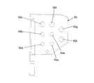
- the pipe holding bracket 55 for holding the work apparatus pipe 54 on the revolving frame 50 side is for two booms connected to the boom cylinder at the inner part located on the revolving center side of the revolving structure. It has holes 55a and 55b into which each of the pipes is inserted, and a hole 55c into which one of the two arm pipes connected to the arm cylinder is inserted.
- the central portion has holes 55d and 55e into which the two bucket pipes connected to the bucket cylinder are inserted, and a hole 55f into which the other one of the arm pipes is inserted.
- the outer portion has holes 55g and 55h into which the two spare pipes connected to the spare actuator are inserted.
- the clamp 56 that holds the work device pipe 54 on the swing post 52 side includes a first sandwiching portion 57 and a second sandwiching portion 58 that face each other, and these first sandwiching portions.
- a hole 56c into which one of the two pipes is inserted, holes 56d and 56e into which each of the two bucket pipes is inserted, and a hole 56f into which the other one of the two pipes for the arm is inserted, and Holes 56g and 56h into which the spare pipes are inserted are formed.
- the working device pipe 54 Due to the holding form of the working device pipe 54 by the pipe holding bracket 55 and the clamp 56, a plurality of boom pipes, arm pipes, bucket pipes, and spare pipes are provided in the vicinity of the connecting pin 53.
- the working device piping is kept in a bundled and dense state, and is inserted into the lateral hole 52a of the swing post 52 while maintaining this state.
- the working device piping 54 is inserted into the lateral hole 52a of the swing post 52 in a state of being bundled and densely packed.
- the force generated by the outward expansion of the boom piping arranged inside, the arm piping arranged in the center, and the bucket piping arranged outside It is easy to be transmitted to spare piping arranged outside without being escaped.
- there is a risk that the pipes arranged on the outside may be pressed against the edge of the horizontal hole 52a of the swing post 52 with a strong force. If such a situation is repeated, there is a concern that the durability of the working device pipe 54 is deteriorated.
- the present invention has been made from the actual state of the above-described prior art, and its purpose is to reduce the pressing force to the edge of the horizontal hole of the swing post of the piping for the working device, which occurs with the swinging of the working device. It is to provide a swivel construction machine that can be used.
- the present invention provides a working device including a plurality of hydraulic actuators, a swing cylinder for swinging the working device in a horizontal direction, and the working device attached thereto, and capable of rotating in the horizontal direction.
- a swing post a bracket connected to the swing post by a connecting pin extending in the vertical direction, a swing body having a swing frame to which the bracket is fixed, and a control valve disposed on the swing body;
- the control valve and a plurality of work device pipes that connect corresponding ones of the plurality of hydraulic actuators are provided, and a portion of the plurality of work device pipes positioned on the swivel frame side is held.
- a swing post side holding body, and the swing post has a horizontal hole into which the plurality of work device pipes are inserted at a position opposite to the swing cylinder across the connecting pin.
- the working device pipe is held between the swing frame side holding body and the horizontal hole of the swing post so as to extend along the horizontal direction, and the working device pipe is connected to the horizontal hole of the swing post.
- the swing frame side holding body includes a first stage holding portion and A plurality of holding sections including a second stage holding section disposed below the first stage holding section, and each of the plurality of holding sections includes a corresponding one of the plurality of working device pipes.
- the plurality of work device pipes inserted into the lateral holes of the swing post by the cooperation of the first clamp and the second clamp are at least two stages of work device pipe groups in the vertical direction. To be kept.
- Each of the plurality of work pipes included in the work pipe group is liable to slip between each other even if adjacent work pipes come into contact with each other. Transmission is suppressed.
- the working device piping included in the working device piping group located on the upper side, and the working device piping included in the working device piping group located on the lower side Even if they come into contact with each other, slipping is likely to occur between the upper working device pipe and the lower working device pipe, and the transmission of force generated by the spreading operation is suppressed by this slipping. Therefore, when each of the plurality of work device pipes expands outward in accordance with the swing of the work device, the force applied to the work pipes arranged outside the plurality of work device pipes is reduced. Transmission is suppressed. That is, it is possible to reduce the pressing force against the edge of the horizontal hole of the swing post of the working device piping, which is caused by the swinging of the working device.
- the present invention is characterized in that, in the above invention, the first clamp is fixed to the bracket, and the cover is provided on the swing post, the second clamp is fixed, and the cover covers the second clamp. Yes.
- the present invention is the above invention, wherein the first clamp has holes for inserting the plurality of work device pipes forming the first stage holding part and the second stage holding part of the first clamp, respectively.
- the rubber is provided in a row in a horizontal direction, and holding rubber that holds the rubber so as not to expand the rubber and is fixed to the bracket.
- the second clamp is the first clamp of the second clamp.
- a rubber in which holes for insertion of the plurality of working device pipes forming the first stage holding part and the second stage holding part are respectively provided in a row in a horizontal direction, and the rubber so as not to expand the rubber. It is characterized by comprising a holding metal fitting that is held and fixed to the cover.
- the swivel construction machine comprises a mini excavator forming a small construction machine
- the working device includes a boom mounted on the swing post so as to be pivotable in the vertical direction, and the boom.
- a boom cylinder that includes an arm that is pivotably attached to the tip of the arm and a bucket that is pivotally attached to the tip of the arm and that forms the hydraulic actuator and drives the boom.
- An arm cylinder that drives the arm, and a bucket cylinder that drives the bucket, and the swing post has a mounting portion for the swing cylinder at a position opposite to the lateral hole across the connecting pin
- the work equipment piping includes the boom piping connected to the boom cylinder and the arm chassis.
- Arm pipe connected to Sunda and is characterized in that it comprises a bucket pipe connected to the bucket cylinder.
- the present invention provides the boom pipe, the arm pipe, and the bucket pipe in each of the above inventions.
- the boom pipe, the arm pipe, And one of each of the two pipes for the bucket is inserted into the hole that forms the first stage holding portion of the first clamp, and the boom pipe, the arm pipe, and the bucket pipe.
- the other one of the two pipes is inserted into the hole forming the second stage holding portion of the first clamp, and in the second clamp, the first clamp Insert the boom pipe, the arm pipe, and the bucket pipe inserted into the hole forming the first stage holding part, and the hole forming the second stage holding part of the first clamp.
- the boom pipe inserted into the hole forming the second stage holding part of the first clamp, the arm pipe being inserted into the hole forming the first stage holding part of the second clamp,
- the bucket pipe is inserted into the hole forming the second stage holding portion of the second clamp.
- a swing frame side holding body that holds a portion positioned on the swing frame side among a plurality of work device pipes connected to a hydraulic actuator included in the work device includes a first stage holding portion, A plurality of holding parts including a second stage holding part disposed below the first stage holding part, and each of the plurality of holding parts corresponds to one of the plurality of working device pipes.
- the swing post-side holding body that holds the portion located on the swing post side of the plurality of work device pipes is held by the first stage holding portion of the first clamp.
- a first stage holding portion that holds a plurality of work device pipes, and a plurality of work device pipes that are disposed above the first stage holding portion and are held by the second stage holding portions of the first clamp.
- Including a second stage holding portion It is the construction of a second clamp having a retaining portion of the stage.
- a plurality of work device piping groups are arranged in the vertical direction in the swing post. Therefore, when the work device is swung to the side opposite to the swing cylinder side, even if adjacent upper work device pipes included in the upper and lower same work device pipe groups come into contact with each other, the slip is caused between them. Can be generated. Further, even when the working device piping included in the upper working device piping group and the working device piping included in the lower working device piping group come into contact with each other, a slip can be generated between them.
- this invention can reduce the pressing force to the edge of the horizontal hole of the swing post of the working device piping generated with the swinging of the working device, and the durability of the working device piping compared to the prior art. Can be improved.
- FIG. 4 is an enlarged cross-sectional view of FIG. 3 A.
- FIG. 4 is an enlarged view of a B cross section of FIG. 3.
- It is a perspective view which shows the attachment form of one piping group among piping for working apparatuses with which this embodiment is equipped.
- It is a perspective view which shows the attachment form of the other piping group among the piping for working apparatuses with which this embodiment is equipped.
- the revolving construction machine is composed of, for example, a mini excavator forming a small construction machine.
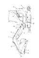
- this mini excavator includes a traveling body 1, a revolving body 2 disposed on the traveling body 1, a driver seat 3 provided on a revolving frame 2 a of the revolving body 2, and a revolving frame. And a counterweight 4 provided at the rear end of 2a.
- the mini excavator is also provided with a working device 7 for excavating soil and the like, a swing post 6 to which the working device 7 is attached and being rotatable in the horizontal direction, and extending vertically on the swing post 6. And a bracket 5 that is connected to the revolving frame 2a.
- the working device 7 includes a boom 8 attached to the swing post 6 so as to be rotatable in the vertical direction, an arm 9 attached to the tip of the boom 8 so as to be rotatable in the vertical direction, and a vertical direction at the tip of the arm 9. And a bucket 10 that is pivotably mounted.
- the working device 7 has one end connected to the swing post 5 and the other end connected to the boom 8.
- the boom cylinder 11 that drives the boom 8, one end connected to the boom 8, and the other end armed 9, an arm cylinder 12 that drives the arm 9, and a bucket cylinder 13 that has one end connected to the arm 9 and the other end connected to the bucket 10 and drives the bucket 10.
- the boom cylinder 11, the arm cylinder 12, and the bucket cylinder 13 constitute a hydraulic actuator included in the work device 7.
- the swing post 6 described above includes an attachment portion 6b to which a swing cylinder (not shown) is attached.
- this mini excavator includes a hydraulic actuator such as a boom cylinder 11, an arm cylinder 12, and a bucket cylinder 13 included in the work device 7, and a turning motor (not shown) that turns the swing body 2.
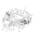
- a control valve 20 for controlling the flow of pressure oil supplied to a travel motor (not shown) that travels the traveling body 1 is disposed on the left side of the revolving frame 2 on the revolving frame 2a in the direction of the working device 7. It is.
- the mini excavator includes a plurality of work device pipes 21 that connect the boom cylinder 11, the arm cylinder 12, the bucket cylinder 13, and the control valve 20 described above.
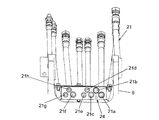
- the work device pipe 21 includes, for example, two spare pipes 21a and 21b, two arm pipes 21c and 21f, two bucket pipes 21d and 21e, and two boom pipes 21g and 21h. It is included.
- the swing post 6 has a horizontal hole 6 a into which a plurality of work device pipes 21 are inserted at a position opposite to a swing cylinder (not shown) across the connecting pin 25.
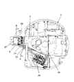
- the mini excavator is a revolving frame side holding body that holds a portion located on the revolving frame 2 a side of the plurality of work device pipes 21, that is, a first clamp 22.
- a swing post-side holding body that holds a portion located on the swing post 6 side of the plurality of work device pipes 21, that is, a second clamp 24 is provided.
- the basic holding form of the plurality of work device pipes 21 is arranged between the first clamp 22 and the horizontal hole 6a of the swing post 6 so as to be along the horizontal direction,
- the working device pipe 21 When inserting the working device pipe 21 into the horizontal hole 6a of the post 6, it is inserted into the horizontal hole 6a of the swing post 6 so as to go around the connecting pin 25, and the extending direction is reversed at a position above the insertion position, In this state, it is clamped by the second clamp 24 and then extended upward so as to be connected to the corresponding hydraulic actuator.
- the first clamp 22 is included in one working pipe group disposed in the same row in the horizontal direction from the inner side which is the turning center side of the turning body 2 toward the outer side.
- a first stage holding part that sandwiches the boom pipe 21g, the bucket pipe 21e, the arm pipe 21c, and the spare pipe 21a, and is arranged below the first stage holding part.
- the 1st clamp 22 with which this embodiment is provided has only the above-mentioned 1st stage holding part and the 2nd stage holding part, for example.
- the second clamps 24 are arranged in the same horizontal row from the swing cylinder side (not shown) toward the side hole 6a side of the swing post 6, respectively.
- a first stage holding part that sandwiches the arm pipe 21f, the bucket pipe 21e, the arm pipe 21c, and the auxiliary pipe 21a, and a swing post that is disposed above the first stage holding part and from the swing cylinder side (not shown)
- a plurality of stages of holding sections including a boom pipe 21h, a bucket pipe 21d, and a second stage holding section 21b that sandwich the spare pipe 21b, which are respectively arranged in the same horizontal row toward the side hole 6a side. have.
- the second clamp 24 provided in the present embodiment also has, for example, only the first stage holding part and the second stage holding part described above.
- this embodiment considers the arrangement
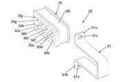
- the first clamp 22 includes a rubber 30 provided with holes for insertion of a plurality of work device pipes 21 forming the above-described first stage holding portion of the first clamp 22, and the rubber.
- the rubber 30 is held so as not to expand, and the holding bracket 31 is fixed to the bracket 5 provided on the revolving frame 2a.
- the rubber 30 is formed with the holes 30g, 30e, 30c, 30a forming the first stage holding portion described above, and the holes 30g, 30e, 30c, 30a that can be expanded when the corresponding working device piping is inserted.
- a groove 30i into which the holding metal fitting 3 is fitted.
- the boom pipe 21g is inserted into the hole 30g of the first stage holding portion of the rubber 30 described above, the bucket pipe 21e is inserted into the hole 30e, the arm pipe 21c is inserted into the hole 30c, and the hole 30a is inserted into the hole 30a.
- the spare piping 21a is inserted.
- the boom pipe 21h is inserted into the hole 30h of the second stage holding portion of the rubber 30 described above, the arm pipe 21f is inserted into the hole 30f, the bucket pipe 21d is inserted into the hole 30d, and the hole 30b is inserted.
- the spare pipe 30b is inserted.
- the holding metal 31 has a U-shaped basic shape and has contact portions 31a and 31b that contact the wall surface 5a of the bracket 5 shown in FIG. Holes 31c and 31d for inserting bolts 46 and 47 shown in FIG. 6 for fixing the holding metal fitting 31 to the wall surface 5a of the bracket 5 are formed in 31b.
- the second post 24 is fixed to the swing post 6, and a cover 23 that covers the second clamp 24 is provided.
- the second clamp 24 is provided with holes for inserting a plurality of work device pipes 21 forming the above-described first stage holding part and second stage holding part of the second clamp 24.
- the rubber 35 and the holding metal fitting 3 that holds the rubber 35 so that the rubber 35 is not expanded and is fixed to the cover 23.
- a hole 23d is formed in a lower portion of the cover 23, and the cover 23 is fixed to the swing post 6 by a bolt 26 inserted into the hole 23d.
- the holding metal fitting 36 has a pair of leg portions 36 b and 36 c that form a recess 36 a that is fitted to the rubber 35, and is formed at an end portion of each of the leg portions 36 b and 36 c and comes into contact with the cover 23.
- holes 36e and 36f are formed which match the holes 23b and 23c formed in the cover 23, respectively.
- nuts 41 and 43 adapted to the holes 36e and 36f are welded to the respective back portions of the contact surfaces.
- a hole 35 i into which the cylindrical member 37 is inserted is formed in the central portion of the rubber 35, and a hole 23 a that matches the hole 35 i is formed in the cover 23.
- a hole 36 d is formed in the holding metal fitting 36 at a position that matches the cylindrical member 35.
- a nut (not shown) is welded to the holding metal part 36 at the back of the hole 36d.
- the holding metal fitting 36 is fixed to the swing post 6 by bolts 45 and 46.
- the leg portions 36b and 36c of the holding metal fitting 36 are fitted so that the rubber 35 is fitted into the recess 36a with the cylindrical member 37 inserted into the hole 35i of the rubber 35.
- the respective contact surfaces are brought into contact with the cover 23, and in this state, the bolt 39 is inserted through the washer 38 into the hole 23a of the cover 23 and the cylindrical member 37 inserted into the hole 35i of the rubber 35, and the holding metal fitting 36. It is inserted into each of the holes 36d and screwed into a nut (not shown) welded to the back of the holding metal fitting 36.
- the bolt 40 is inserted into each of the hole 23 b of the cover 23 and the hole 36 e of the contact surface of the leg portion 36 b of the holding metal 36 and screwed into the nut 41.
- the bolt 42 is inserted into each of the hole 23 c of the cover 23 and the hole 36 f of the contact surface of the leg portion 36 c of the holding metal 36 and screwed into the nut 43.
- the rubber 35 of the second clamp 24 has holes 35g, 35f, 35e, 35c, and 35a that form the first step holding portion of the second clamp 24, and a hole that forms the second step holding portion of the second clamp 24. 35h, 35d, and 35b.
- Each of the holes 35g, 35f, 35e, 35c, 35a and the holes 35h, 35d, 35b is provided with a notch on the lower end side to allow the holes to be expanded when the corresponding working device pipe is inserted. Alternatively, it is formed on the upper end side.
- the boom pipe 21g is inserted into the hole 35g of the first stage holding portion of the rubber 35 described above, the arm pipe 21f is inserted into the hole 35f, the bucket pipe 21e is inserted into the hole 35e, and the hole 35c is inserted into the hole 35c.
- the arm pipe 21c is inserted, and the spare pipe 21a is inserted into the hole 35a.
- the boom pipe 21h is inserted into the hole 35h of the second stage holding portion of the rubber 35 described above, the bucket pipe 21d is inserted into the hole 35d, and the spare pipe 21b is inserted into the hole 35b.
- the plurality of work device pipes 21 inserted into the horizontal holes 6a of the swing post 6 are basically in the vertical direction by the cooperation of the first clamp 22 and the second clamp 24. It is kept in a two-stage working equipment piping group.
- the upper stage of the first clamp 22 Even if the adjacent work pipes among the spare pipe 21a, the arm pipe 21c, the bucket pipe 21e, and the boom pipe 21g included in the work device pipe group in the same row may contact each other, Alternatively, in the first clamp 22, adjacent work device pipes among the spare pipe 21b, the bucket pipe 21d, the arm pipe 21f, and the boom pipe 21h included in the lower row of the work apparatus pipe group. Even if they come into contact with each other, a slip is likely to occur between them, and this slip suppresses the transmission of force generated in accordance with the expanding operation.
- any one of the spare pipe 21a, the arm pipe 21c, the bucket pipe 21e, and the boom pipe 21g included in the upper work device pipe group in the first clamp 22 is selected. Even if any one of the auxiliary pipe 21b, the bucket pipe 21d, the arm pipe 21f, and the boom pipe 21h included in the lower working apparatus pipe group contacts the first clamp 22, the upper stage Slip is likely to occur between the working device pipe and the lower working device pipe, and transmission of force generated in accordance with the expanding operation is suppressed by this slip.
- the first clamp 22 has a first stage holding part and a second stage holding part for holding different working device piping groups, but the working device piping is provided in the swing post 6.
- a third stage holding part that holds the working device piping group may be provided below the second stage holding part.
- the second clamp 24 is also provided with a third stage holding part capable of holding the working device piping group held by the third stage holding part above the second stage holding part of the second clamp 24.
- the configuration provided in. Those configured in this way are adjacent to each other when the working device 7 included in each working device piping group is expanded when the working device 7 is swung to the opposite side of a swing cylinder (not shown).
Landscapes
- Engineering & Computer Science (AREA)
- Mining & Mineral Resources (AREA)
- Civil Engineering (AREA)
- General Engineering & Computer Science (AREA)
- Structural Engineering (AREA)
- Mechanical Engineering (AREA)
- Component Parts Of Construction Machinery (AREA)
- Jib Cranes (AREA)
Abstract
Priority Applications (4)
| Application Number | Priority Date | Filing Date | Title |
|---|---|---|---|
| US14/128,898 US8920105B2 (en) | 2011-06-24 | 2012-06-18 | Rotation-type construction machine |
| CN201280031103.3A CN103717806B (zh) | 2011-06-24 | 2012-06-18 | 回转式工程机械 |
| KR1020147000797A KR101853804B1 (ko) | 2011-06-24 | 2012-06-18 | 선회식 건설 기계 |
| EP12801988.2A EP2725150A4 (fr) | 2011-06-24 | 2012-06-18 | Machine de construction du type à rotation |
Applications Claiming Priority (2)
| Application Number | Priority Date | Filing Date | Title |
|---|---|---|---|
| JP2011140930A JP5525488B2 (ja) | 2011-06-24 | 2011-06-24 | 旋回式建設機械 |
| JP2011-140930 | 2011-06-24 |
Publications (1)
| Publication Number | Publication Date |
|---|---|
| WO2012176729A1 true WO2012176729A1 (fr) | 2012-12-27 |
Family
ID=47422566
Family Applications (1)
| Application Number | Title | Priority Date | Filing Date |
|---|---|---|---|
| PCT/JP2012/065499 Ceased WO2012176729A1 (fr) | 2011-06-24 | 2012-06-18 | Machine de construction du type à rotation |
Country Status (6)
| Country | Link |
|---|---|
| US (1) | US8920105B2 (fr) |
| EP (1) | EP2725150A4 (fr) |
| JP (1) | JP5525488B2 (fr) |
| KR (1) | KR101853804B1 (fr) |
| CN (1) | CN103717806B (fr) |
| WO (1) | WO2012176729A1 (fr) |
Cited By (3)
| Publication number | Priority date | Publication date | Assignee | Title |
|---|---|---|---|---|
| NL2012449A (en) * | 2013-03-29 | 2014-09-30 | Hitachi Construction Machinery | Seven-ton class hydraulic excavator. |
| CN104246082A (zh) * | 2013-03-29 | 2014-12-24 | 株式会社小松制作所 | 向发电机马达搭载柴油氧化催化剂装置的搭载结构 |
| US20160091123A1 (en) * | 2013-05-30 | 2016-03-31 | Seong-Geun Yun | Pipe fixing device for construction machine |
Families Citing this family (16)
| Publication number | Priority date | Publication date | Assignee | Title |
|---|---|---|---|---|
| JP5403013B2 (ja) * | 2011-08-24 | 2014-01-29 | コベルコ建機株式会社 | 作業機械における配管取付け構造 |
| CN103958786A (zh) * | 2011-11-30 | 2014-07-30 | 沃尔沃建造设备有限公司 | 用于动臂回转式挖掘机的液压管路固定装置 |
| JP6152004B2 (ja) * | 2013-07-30 | 2017-06-21 | ヤンマー株式会社 | 建設機械の配管構造 |
| JP6682262B2 (ja) * | 2015-12-24 | 2020-04-15 | 株式会社クボタ | 作業機 |
| JP6350564B2 (ja) * | 2016-03-01 | 2018-07-04 | コベルコ建機株式会社 | 建設機械のバルブ配設構造 |
| JP1577338S (fr) * | 2016-08-30 | 2017-05-29 | ||
| US10578232B2 (en) | 2017-09-06 | 2020-03-03 | Lsp Products Group, Inc. | Pipe hanger system |
| KR102428131B1 (ko) * | 2019-03-29 | 2022-08-02 | 히다찌 겐끼 가부시키가이샤 | 작업 기계 |
| JP7183116B2 (ja) * | 2019-06-04 | 2022-12-05 | 株式会社クボタ | 作業機 |
| JP7126994B2 (ja) * | 2019-06-26 | 2022-08-29 | 株式会社クボタ | 作業機 |
| JP7346984B2 (ja) * | 2019-07-31 | 2023-09-20 | コベルコ建機株式会社 | 建設機械の旋回体、および建設機械の旋回体の組立方法 |
| USD969878S1 (en) | 2019-09-30 | 2022-11-15 | Kubota Corporation | Backhoe loader |
| JP7166306B2 (ja) * | 2020-03-26 | 2022-11-07 | 株式会社日立建機ティエラ | 建設機械 |
| JP7404152B2 (ja) | 2020-05-11 | 2023-12-25 | 株式会社クボタ | 配策部材のガイド構造及び作業機 |
| AU2021232719B2 (en) * | 2021-09-15 | 2023-07-06 | Komatsu Forest Ab | Internal line routing for working machines having boom arms |
| JP2024142157A (ja) * | 2023-03-29 | 2024-10-10 | ヤンマーホールディングス株式会社 | 建設機械 |
Citations (4)
| Publication number | Priority date | Publication date | Assignee | Title |
|---|---|---|---|---|
| JP2004036233A (ja) | 2002-07-03 | 2004-02-05 | Hitachi Constr Mach Co Ltd | 旋回式建設機械 |
| JP2004100173A (ja) * | 2002-09-05 | 2004-04-02 | Komatsu Ltd | 左右スイング式作業機装置の油圧配管構造 |
| JP2004353401A (ja) * | 2003-05-30 | 2004-12-16 | Hitachi Constr Mach Co Ltd | ホースクランプ装置 |
| JP2005060977A (ja) * | 2003-08-08 | 2005-03-10 | Hitachi Constr Mach Co Ltd | 旋回式建設機械 |
Family Cites Families (12)
| Publication number | Priority date | Publication date | Assignee | Title |
|---|---|---|---|---|
| US2903145A (en) * | 1957-04-04 | 1959-09-08 | Sherman Products Inc | Valve control |
| US3082890A (en) * | 1960-07-25 | 1963-03-26 | Deere & Co | Earth moving implement |
| US3120897A (en) * | 1962-12-03 | 1964-02-11 | Deere & Co | Backhoe |
| US3236394A (en) * | 1964-01-17 | 1966-02-22 | Deere & Co | Supporting structure for an earth moving implement |
| JP4005429B2 (ja) * | 2002-07-03 | 2007-11-07 | 日立建機株式会社 | 旋回式建設機械 |
| JP2004285702A (ja) * | 2003-03-24 | 2004-10-14 | Komatsu Ltd | スイング式油圧ショベルの配管取り回し構造 |
| JP4084242B2 (ja) | 2003-05-30 | 2008-04-30 | 日立建機株式会社 | 建設機械 |
| JP2005060976A (ja) | 2003-08-08 | 2005-03-10 | Hitachi Constr Mach Co Ltd | 旋回式建設機械 |
| JP4720499B2 (ja) | 2005-12-28 | 2011-07-13 | コベルコ建機株式会社 | 作業機械 |
| JP4705056B2 (ja) * | 2007-02-16 | 2011-06-22 | 日立建機株式会社 | 建設機械 |
| JP4648357B2 (ja) * | 2007-05-16 | 2011-03-09 | 日立建機株式会社 | 旋回式建設機械 |
| JP5425508B2 (ja) * | 2009-03-30 | 2014-02-26 | 矢崎総業株式会社 | モーターケーブル装置、及び、モーターケーブル装置のケーブル本体製造方法 |
-
2011
- 2011-06-24 JP JP2011140930A patent/JP5525488B2/ja active Active
-
2012
- 2012-06-18 KR KR1020147000797A patent/KR101853804B1/ko active Active
- 2012-06-18 US US14/128,898 patent/US8920105B2/en active Active
- 2012-06-18 CN CN201280031103.3A patent/CN103717806B/zh active Active
- 2012-06-18 WO PCT/JP2012/065499 patent/WO2012176729A1/fr not_active Ceased
- 2012-06-18 EP EP12801988.2A patent/EP2725150A4/fr not_active Withdrawn
Patent Citations (4)
| Publication number | Priority date | Publication date | Assignee | Title |
|---|---|---|---|---|
| JP2004036233A (ja) | 2002-07-03 | 2004-02-05 | Hitachi Constr Mach Co Ltd | 旋回式建設機械 |
| JP2004100173A (ja) * | 2002-09-05 | 2004-04-02 | Komatsu Ltd | 左右スイング式作業機装置の油圧配管構造 |
| JP2004353401A (ja) * | 2003-05-30 | 2004-12-16 | Hitachi Constr Mach Co Ltd | ホースクランプ装置 |
| JP2005060977A (ja) * | 2003-08-08 | 2005-03-10 | Hitachi Constr Mach Co Ltd | 旋回式建設機械 |
Non-Patent Citations (1)
| Title |
|---|
| See also references of EP2725150A4 |
Cited By (4)
| Publication number | Priority date | Publication date | Assignee | Title |
|---|---|---|---|---|
| NL2012449A (en) * | 2013-03-29 | 2014-09-30 | Hitachi Construction Machinery | Seven-ton class hydraulic excavator. |
| CN104246082A (zh) * | 2013-03-29 | 2014-12-24 | 株式会社小松制作所 | 向发电机马达搭载柴油氧化催化剂装置的搭载结构 |
| CN104246082B (zh) * | 2013-03-29 | 2016-05-04 | 株式会社小松制作所 | 向发电机马达搭载柴油氧化催化剂装置的搭载结构 |
| US20160091123A1 (en) * | 2013-05-30 | 2016-03-31 | Seong-Geun Yun | Pipe fixing device for construction machine |
Also Published As
| Publication number | Publication date |
|---|---|
| US20140140799A1 (en) | 2014-05-22 |
| JP2013007217A (ja) | 2013-01-10 |
| KR101853804B1 (ko) | 2018-05-02 |
| EP2725150A4 (fr) | 2015-06-10 |
| EP2725150A1 (fr) | 2014-04-30 |
| CN103717806A (zh) | 2014-04-09 |
| CN103717806B (zh) | 2016-06-22 |
| US8920105B2 (en) | 2014-12-30 |
| JP5525488B2 (ja) | 2014-06-18 |
| KR20140051227A (ko) | 2014-04-30 |
Similar Documents
| Publication | Publication Date | Title |
|---|---|---|
| JP5525488B2 (ja) | 旋回式建設機械 | |
| JP5106657B1 (ja) | 油圧ショベル | |
| JP5301480B2 (ja) | 建設機械 | |
| CN204510334U (zh) | 工程机械 | |
| JP6064773B2 (ja) | 油圧ホース配設構造 | |
| JP5667954B2 (ja) | 作業機械 | |
| JP2009085000A (ja) | 小旋回式掘削機用油圧配管固定装置 | |
| JP2010059734A (ja) | ローダ作業機 | |
| JP5639099B2 (ja) | 配管クランプ具及び作業機の配管固定構造 | |
| JP4365506B2 (ja) | アタッチメント連結装置 | |
| JP4757272B2 (ja) | 建設機械の油圧ホースクランプ装置 | |
| JP4720793B2 (ja) | クローラ式作業機械の油圧配管構造 | |
| JP5949076B2 (ja) | 作業機械 | |
| JP2013087468A (ja) | 建設機械の配管クランプ装置 | |
| JP3820113B2 (ja) | 掘削作業機 | |
| JP2005068962A (ja) | 建設機械の燃料配管構造 | |
| JP4781416B2 (ja) | 建設機械 | |
| JP6149875B2 (ja) | 建設機械のエンジン支持構造及びその組立方法 | |
| JP2004353400A (ja) | 建設機械 | |
| JP5456334B2 (ja) | フロント作業機 | |
| JP2014202029A (ja) | 建設機械の配索構造 | |
| JP2008240353A (ja) | 作業機械の油圧配管構造及びこれを備えた作業機械 | |
| JP2018053571A (ja) | アダプタ構造 | |
| JP2015137465A (ja) | 建設機械の配索構造 | |
| JP2016061122A (ja) | ショベルのアタッチメント配管構造 |
Legal Events
| Date | Code | Title | Description |
|---|---|---|---|
| 121 | Ep: the epo has been informed by wipo that ep was designated in this application |
Ref document number: 12801988 Country of ref document: EP Kind code of ref document: A1 |
|
| WWE | Wipo information: entry into national phase |
Ref document number: 14128898 Country of ref document: US |
|
| NENP | Non-entry into the national phase |
Ref country code: DE |
|
| ENP | Entry into the national phase |
Ref document number: 20147000797 Country of ref document: KR Kind code of ref document: A |
|
| WWE | Wipo information: entry into national phase |
Ref document number: 2012801988 Country of ref document: EP |