WO2012176894A1 - Système de communication, procédé de communication et station enfant d'un système de communication - Google Patents
Système de communication, procédé de communication et station enfant d'un système de communication Download PDFInfo
- Publication number
- WO2012176894A1 WO2012176894A1 PCT/JP2012/066046 JP2012066046W WO2012176894A1 WO 2012176894 A1 WO2012176894 A1 WO 2012176894A1 JP 2012066046 W JP2012066046 W JP 2012066046W WO 2012176894 A1 WO2012176894 A1 WO 2012176894A1
- Authority
- WO
- WIPO (PCT)
- Prior art keywords
- period
- slave station
- station
- master station
- aware
- Prior art date
- Legal status (The legal status is an assumption and is not a legal conclusion. Google has not performed a legal analysis and makes no representation as to the accuracy of the status listed.)
- Ceased
Links
Images








Classifications
-
- H—ELECTRICITY
- H04—ELECTRIC COMMUNICATION TECHNIQUE
- H04W—WIRELESS COMMUNICATION NETWORKS
- H04W52/00—Power management, e.g. Transmission Power Control [TPC] or power classes
- H04W52/02—Power saving arrangements
- H04W52/0209—Power saving arrangements in terminal devices
- H04W52/0212—Power saving arrangements in terminal devices managed by the network, e.g. network or access point is leader and terminal is follower
-
- H—ELECTRICITY
- H04—ELECTRIC COMMUNICATION TECHNIQUE
- H04J—MULTIPLEX COMMUNICATION
- H04J3/00—Time-division multiplex systems
- H04J3/02—Details
- H04J3/06—Synchronising arrangements
- H04J3/0635—Clock or time synchronisation in a network
- H04J3/0638—Clock or time synchronisation among nodes; Internode synchronisation
- H04J3/0652—Synchronisation among time division multiple access [TDMA] nodes, e.g. time triggered protocol [TTP]
-
- H—ELECTRICITY
- H04—ELECTRIC COMMUNICATION TECHNIQUE
- H04L—TRANSMISSION OF DIGITAL INFORMATION, e.g. TELEGRAPHIC COMMUNICATION
- H04L12/00—Data switching networks
- H04L12/02—Details
- H04L12/12—Arrangements for remote connection or disconnection of substations or of equipment thereof
-
- H—ELECTRICITY
- H04—ELECTRIC COMMUNICATION TECHNIQUE
- H04L—TRANSMISSION OF DIGITAL INFORMATION, e.g. TELEGRAPHIC COMMUNICATION
- H04L12/00—Data switching networks
- H04L12/28—Data switching networks characterised by path configuration, e.g. LAN [Local Area Networks] or WAN [Wide Area Networks]
- H04L12/40—Bus networks
- H04L12/403—Bus networks with centralised control, e.g. polling
-
- H—ELECTRICITY
- H04—ELECTRIC COMMUNICATION TECHNIQUE
- H04Q—SELECTING
- H04Q11/00—Selecting arrangements for multiplex systems
- H04Q11/0001—Selecting arrangements for multiplex systems using optical switching
- H04Q11/0062—Network aspects
- H04Q11/0067—Provisions for optical access or distribution networks, e.g. Gigabit Ethernet Passive Optical Network (GE-PON), ATM-based Passive Optical Network (A-PON), PON-Ring
-
- H—ELECTRICITY
- H04—ELECTRIC COMMUNICATION TECHNIQUE
- H04Q—SELECTING
- H04Q11/00—Selecting arrangements for multiplex systems
- H04Q11/0001—Selecting arrangements for multiplex systems using optical switching
- H04Q11/0062—Network aspects
- H04Q2011/0079—Operation or maintenance aspects
-
- H—ELECTRICITY
- H04—ELECTRIC COMMUNICATION TECHNIQUE
- H04Q—SELECTING
- H04Q2213/00—Indexing scheme relating to selecting arrangements in general and for multiplex systems
- H04Q2213/1301—Optical transmission, optical switches
-
- H—ELECTRICITY
- H04—ELECTRIC COMMUNICATION TECHNIQUE
- H04Q—SELECTING
- H04Q2213/00—Indexing scheme relating to selecting arrangements in general and for multiplex systems
- H04Q2213/1308—Power supply
-
- H—ELECTRICITY
- H04—ELECTRIC COMMUNICATION TECHNIQUE
- H04Q—SELECTING
- H04Q2213/00—Indexing scheme relating to selecting arrangements in general and for multiplex systems
- H04Q2213/1336—Synchronisation
-
- Y—GENERAL TAGGING OF NEW TECHNOLOGICAL DEVELOPMENTS; GENERAL TAGGING OF CROSS-SECTIONAL TECHNOLOGIES SPANNING OVER SEVERAL SECTIONS OF THE IPC; TECHNICAL SUBJECTS COVERED BY FORMER USPC CROSS-REFERENCE ART COLLECTIONS [XRACs] AND DIGESTS
- Y02—TECHNOLOGIES OR APPLICATIONS FOR MITIGATION OR ADAPTATION AGAINST CLIMATE CHANGE
- Y02D—CLIMATE CHANGE MITIGATION TECHNOLOGIES IN INFORMATION AND COMMUNICATION TECHNOLOGIES [ICT], I.E. INFORMATION AND COMMUNICATION TECHNOLOGIES AIMING AT THE REDUCTION OF THEIR OWN ENERGY USE
- Y02D30/00—Reducing energy consumption in communication networks
- Y02D30/70—Reducing energy consumption in communication networks in wireless communication networks
Definitions
- the present invention relates to a communication system, a communication method, and a slave station of the communication system.
- the normal mode is changed to a power saving mode in which some or all of the functions are stopped.
- the present invention relates to a communication method for changing stations.
- PON Passive Optical Network
- OLT Optical Line Terminal
- ONU Optical Network Unit
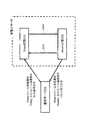
- FIG. 1 shows the configuration of the PON system 1.
- PON system 1 includes a OLT2 installed in the station, a plurality of m ONU 3 -1 installed to each user's home, 3-2, ..., 3 and -m, the plurality of m Of the optical fiber 4 and the optical splitter 5 connecting the ONUs 3 (3 ⁇ 1 , 3 ⁇ 2 ,..., 3 ⁇ m ) of 1: m.
- An external network 6 is connected to the OLT 2.
- a section connecting each ONU 3 and the OLT 2 by the optical fiber 4 and the optical splitter 5 is referred to as a PON section 7.
- OLT 2 periodically transmits a reference time to each ONU 3 in accordance with this rule, and notifies each ONU 3 of a time at which each ONU 3 may transmit a signal.
- Each ONU 3 sets its own local time to the reference time received from the OLT 2 and, when the local time reaches a specified time, transmits a signal to communicate with the OLT 2.
- an ONU 3 is installed in each user house. Therefore, the power consumption of all ONUs 3 is large in the power consumption of the entire network, and the ONU 3 is required to save power.
- the ONU 3 As a power saving method of the ONU 3, there is, for example, a Cyclic Sleep method (for example, see Non-Patent Document 3).
- the ONU 3 has two modes, a power saving mode and a normal mode.
- the power saving mode is a mode in which the ONU 3 performs Cyclic Sleep
- the normal mode is a mode in which Cyclic Sleep is not performed.
- the ONU 3 in the power saving mode is configured to periodically repeat the Sleep state and the Aware state.
- the sleep state means a state where a part or all of the device is stopped and the use of power is suppressed
- the Aware state means a state where the device is started and the use of power is not suppressed.
- a period in which the ONU 3 is in the Sleep state is referred to as a Sleep period
- a period in which the ONU 3 is in the Aware state is referred to as an Aware period.
- the period from the start of the sleep period to the end of the Aware period is called one cycle.
- a signal transmitted and received between the OLT 2 and each ONU 3 is called a frame in order to distinguish it from a signal inside the apparatus.
- the frame includes a user frame and a control frame.
- the user frame is a general term for frames exchanged between the external network 6 and the home network
- the control frame is a frame other than the user frame (a sleep frame described later). , Sleep_Ack frame, Aware frame, Aware_Ack frame, etc.).
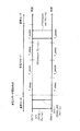
- Cyclic Sleep method The communication process of this Cyclic Sleep method is shown in Fig. 2 below.
- the OLT 2 instructs the ONU 3 to shift from the normal mode to the power saving mode or to return from the power saving mode to the normal mode.
- the OLT 2 determines that the specific ONU 3 is to be in the power saving mode based on the communication amount and the like, and a control frame (in this case, a Sleep frame) for instructing it is shown in step ST1. At that time, it transmits to the corresponding ONU3. The ONU 3 that has received this Sleep frame returns a control frame (in this case, a Sleep_Ack frame) notifying that the transition to the power saving mode has been accepted to the OLT 2 at the time of step ST2.
- a control frame in this case, a Sleep_Ack frame
- the ONU 3 enters the sleep state for a sleep period (hereinafter referred to as “T_sleep”) set in advance after transmitting the Sleep_Ack frame to the OLT 2.
- T_sleep a sleep period
- the ONU 3 enters the Aware state only for an Aware period (hereinafter referred to as “T_aware”) set in advance. If nothing is instructed from the OLT 2 before the end of the Aware period, the ONU 3 again enters a sleep state for T_sleep, and thereafter this is repeated periodically.
- a control frame (in this case, an Aware frame) for the OLT 2 to instruct the return from the power saving mode is sent to the ONU 3 at the time of step ST3. Send it out.
- the ONU 3 Upon receiving this Aware frame, the ONU 3 returns from the power saving mode to the normal mode, and transmits a control frame (in this case, an Aware_Ack frame) for notifying it to the OLT 2 at the time of step ST4. Thereafter, the ONU 3 is in the normal mode until a control frame (Sleep frame) is received from the OLT 2 again.
- the time when the sleep period starts in the first cycle is called the power saving mode start time, and the power saving mode start time is synchronized between the OLT 2 and the ONU 3.
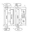
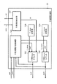
- FIG. 3 shows a specific configuration example of the OLT 2 and the ONU 3 in which the above-described Cyclic Sleep method is implemented.
- the OLT 2 includes a master station communication unit 21 and master station power control units 22 -1 to 22 -m corresponding to the number of ONUs (m) connected to the OLT 2.
- the OLT 2 is implemented with a protocol defined by the non-patent document 1 or the non-patent document 2 for the master station communication unit 21.
- the OLT 2 maintains a connection with the ONU 3 and is input from the external network 6 while transmitting a control frame for periodically reporting the reference time from the master station communication unit 21 to the ONU 3 via the PON section 7.
- the user frame is transmitted to the ONU 3 via the master station communication unit 21 and the PON section 7.
- the OLT 2 transmits a user frame input from the home network 8 to the ONU 3 and transmitted from the ONU 3 via the PON section 7 to the external network 6 via the master station communication unit 21.
- the m master station power control units 22 (22 ⁇ 1 to 22 ⁇ m ) in the OLT 2 correspond to each ONU 3 connected to the OLT 2 and whether each ONU 3 should be in the power saving mode or the normal mode.
- the communication amount Q1 of the corresponding ONU 3 is input from the parent station communication unit 21 to each parent station power control unit 22, and the parent station power control unit 22 saves the corresponding ONU 3 based on the communication amount Q1.
- each master station power control unit 22 of the OLT 2 instructs the master station communication unit 21 to transmit the control frame CF by the control signal C1, and the master station communication unit 21 follows the transmission instruction, such as the above-mentioned Sleep frame, Aware frame, etc. Control frame CF is generated and transmitted to the corresponding ONU 3.
- the ONU 3 includes a slave station communication unit 31, a slave station power control unit 32, and a slave station period measurement unit 33.
- the ONU 3 implements a communication protocol similar to that of the OLT 2 for the slave station communication unit 31, and synchronizes the local time of the ONU 3 with the reference time of the OLT 2 based on the reference time transmitted from the OLT 2. Stay connected with.
- the ONU 3 transmits the user frame UF input from the home network 8 from the slave station communication unit 31 to the OLT 2 via the PON section 7, while the user frame UF input from the OLT 2 via the PON section 7 to the child frame UF
- the data is transmitted to the home network 8 by the station communication unit 31.
- the slave station communication unit 31 of the ONU 3 controls the stop or start of the communication function by the stop / start signal SPST input from the slave station power control unit 32 when the ONU 3 enters the sleep state or the Aware state. Do.
- the slave station power control unit 32 of the ONU 3 receives the control frame CF from the OLT 2 via the slave station communication unit 31 and manages whether the ONU 3 should be in the power saving mode or the normal mode. That is, when receiving the control frame (Sleep frame) CF from the OLT 2, the slave station communication unit 31 of the ONU 3 notifies the slave station power control unit 32 of the content of the control frame (Sleep frame) CF by the control signal C2. As a result, when the slave station power control unit 32 of the ONU 3 shifts from the normal mode to the power saving mode based on the control signal C2, the slave state and the Aware state are repeated for a certain period, and the slave station period measurement unit 33 The Sleep period and Aware period are measured.
- the slave station power control unit 32 outputs the set signal SET and the reset signal RSET to the slave station period measurement unit 33, and the slave station period measurement unit 33 sends the sleep state signal SLM and the Aware state signal AWM to the slave station power.
- the set signal SET is a signal that causes the slave station period measurement unit 33 to start measurement of the Sleep period and the Aware period
- the reset signal RSET is a signal that stops the measurement.
- the Sleep state signal SLM is a signal output during the Sleep period
- the Aware state signal AWM is a signal output during the Aware period.
- the slave station power control unit 32 outputs the set signal SET to the slave station period measurement unit 33, and the slave station period measurement unit 33 measures the sleep period and the Aware period. To start. Then, the ONU 3 determines whether the ONU 3 is in the sleep state or the Aware state based on the sleep state signal SLM and the Aware state signal AWM from the slave station period measuring unit 33, and the slave station power control unit 32
- the station communication unit 31 is instructed to stop / start the communication function by outputting a stop / start signal SPST.
- the ONU 3 stops the reception function of the slave station communication unit 31 when in the Sleep state, and therefore cannot receive the control frame (Sleep frame or Aware frame) CF from the OLT 2. Therefore, in order to return the ONU 3 from the power saving mode to the normal mode, it is necessary to transmit a return instruction control frame (Aware frame) CF from the OLT 2 when the ONU 3 is in the Aware state.
- IEEE Std 802.3-2005 Part 3: Carrier sense multiple access with Collision Detection (CSMA / CD) access method and physical layer specifications IEEE Std 802,3avTM-2009: Part 3 Carrier Sense Multiple Access Access Collision Detection (CSMA / CD) access method and physical layer specifications Ryogo Kubo.Jun-ichi kani, Yukihiro Fujimoto, Naoto Yoshimoto and Kiyomi Kumozaki, "Sleep and adaptive link rate control for power saving in 10G-EPON systems '' Proceedings of the IEEE Global TeOBE-6Conference, 2009 2009.
- the present invention synchronizes a master station and a slave station while taking into account an error ( ⁇ t) in measurement of a sleep period and an Aware period, and a control frame for a return instruction from the master station
- ⁇ t error
- the communication system, the slave station device of the communication system, the communication method, and the program that can improve the band utilization efficiency and reduce the power consumption of the master station by reducing the number of times of transmitting the message.
- the communication system of the present invention includes a master station and one or more slave stations, and the master station has a reference time, In the normal mode in which the master station communication unit and the slave station should be in a power saving mode in which a part or the whole of the apparatus is periodically stopped or operated without stopping the part or the whole of the apparatus.
- One or a plurality of master station power control units that determine whether or not to instruct the slave station to change the mode, and a stop period in which a part or all of the slave station devices are stopped in the power saving mode And one or a plurality of master station period measuring units for measuring a non-stop period that is not stopped, and the slave station synchronizes the reference time of the master station and the local time of the slave station
- the slave station communication unit that communicates with the master station
- a slave station power control unit that changes the mode between the power saving mode and the normal mode in the slave station according to the mode change instruction, and a slave that measures the stop period and the non-stop period of the slave station.
- the slave station period measurement unit is obtained by calculating a difference between the reference time of the master station generated during the power saving mode and the local time of the slave station. Using the error, correction is performed for the stop period, the non-stop period, or both periods in the power saving mode.
- the master station includes a master station and one or more slave stations that communicate with the master station, and the master station uses the master station communication unit having a reference time to transmit the plurality of slave stations.
- the time synchronization step of synchronizing the reference time of the slave station and the local time of the slave station, and the master station should be in a power saving mode in which the slave station periodically stops part or all of the device, or a device
- a mode change instructing step for determining whether or not the normal mode should be operated without stopping a part or all of the master station by one or a plurality of master station power control units and instructing the slave station to change the mode; Is the mode from the master station.
- the master station includes one or more master stations
- the master station is composed of a master station and one or a plurality of slave stations, and the master station has a reference time and communicates with the slave stations. And whether the slave station should be in a power saving mode in which part or all of the device is periodically stopped or in a normal mode in which operation is performed without stopping part or all of the device, One or a plurality of master station power control units for instructing the slave station to change the mode, a stop period during which a part or all of the slave station devices are stopped in the power saving mode, and a non-stop that has not been stopped One or a plurality of master station period measuring units for measuring a period, and the slave station performs communication while synchronizing a reference time of the master station and a local time of the slave station And the mode change instruction from the master station A slave station power control unit that changes modes between the power saving mode and the normal mode in the slave station, and a slave station period measurement unit that measures the stop period and the non-stop period of the slave station.
- the slave station period measuring unit obtains an error by calculating a difference between a reference time of the master station generated during the power saving mode and the local time of the slave station; Transmitted to the master station by a station communication unit, and the master station period measurement unit uses the error received from the slave station by the master station communication unit, in the power saving mode, the stop period or the non-stop period or The correction is performed for both periods.
- the master station is composed of a master station and one or more slave stations that communicate with the master station, and the master station uses the master station communication unit having a reference time to transmit the plurality of slave stations.
- the time synchronization step of synchronizing the reference time of the slave station and the local time of the slave station, and the master station should be in a power saving mode in which the slave station periodically stops part or all of the device, or a device
- a mode change instructing step for determining whether or not the normal mode should be operated without stopping a part or all of the master station by one or a plurality of master station power control units and instructing the slave station to change the mode; Is the mode from the master station.
- An error is obtained by calculating a difference between the reference time of the master station and the local time of the slave station, and the error is transmitted to the master station by the slave station communication unit.
- the master station period measurement step Using the error received from the slave station by a master station communication unit, and performs correction for the suspension period or the non-stop period or its both periods in the power saving mode.
- the slave station communication unit that performs communication while synchronizing the reference time of the master station of the communication system and its own local time, and the mode change instruction from the master station
- the slave station power control unit that changes the mode between a power saving mode that periodically stops part or all of the apparatus and a normal mode that operates without stopping part or all of the apparatus
- a slave station period measuring unit that measures a stop period in which a part or the whole of the slave station device is stopped in a power mode and a non-stop period that is not stopped, and Using the error obtained by calculating the difference between the reference time of the master station generated during the power saving mode and the local time of the own station, the stop period or the non-stop period in the power save mode or And performing correction for both periods of.
- the slave station's child time is synchronized with the reference time of the parent station that constitutes the communication system and the local time of the child station that constitutes the communication system and is connected to the parent station.
- a mode change step performed by the slave station power control unit, a stop period in which a part or the whole of the slave station apparatus is stopped in the power saving mode, and a non-stop period in which the slave station is not stopped are set as the slave station period of the slave station
- the present invention using the error between the reference time of the master station and the local time of the slave station that occurs during the power saving mode, correction is made for the stop period and / or the non-stop period in the power save mode.
- the control frame from the master station can be reliably transferred to the slave station, and thus the number of times the control frame of the return instruction is transmitted from the master station can be reduced. It is possible to reduce the power consumption of the master station by reducing the band utilization efficiency.
- FIG. 1 is a block diagram showing the overall configuration of the PON system.
- FIG. 2 is a diagram for explaining a communication process in a conventional PON system.
- FIG. 3 is a block diagram showing a circuit configuration of the OLT and ONU.
- FIG. 4 is a diagram for explaining a case where it is not possible to return from the power saving mode to the normal mode in the communication process in the conventional PON system.
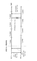
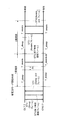
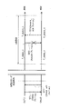
- FIG. 5 is a diagram for explaining correction in consideration of an error when returning from the power saving mode to the normal mode in the communication process of the first embodiment.
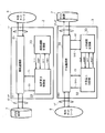
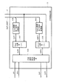
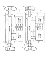
- FIG. 6 is a block diagram showing a circuit configuration of the OLT and ONU corresponding to the first embodiment.
- FIG. 7 is a timing chart showing an operation example of the OLT and ONU corresponding to the first embodiment.
- FIG. 1 is a block diagram showing the overall configuration of the PON system.
- FIG. 2 is a diagram for explaining a communication process in a conventional PON system.
- FIG. 3 is a block diagram showing
- FIG. 8 is a state transition diagram for explaining the processing flow of the master station power control unit in the first embodiment.
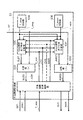
- FIG. 9 is a block diagram illustrating a configuration of the master station period measurement unit in the first embodiment.
- FIG. 10 is a state transition diagram for explaining the processing flow of the slave station power control unit in the first embodiment.
- FIG. 11 is a block diagram illustrating a configuration of a slave station period measurement unit according to the first embodiment.
- FIG. 12 is a diagram for explaining correction in consideration of an error when returning from the power saving mode to the normal mode in the communication process according to the second embodiment.
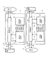
- FIG. 13 is a block diagram showing a circuit configuration of the OLT and ONU corresponding to the second embodiment.
- FIG. 14 is a block diagram illustrating a configuration of a slave station period measurement unit according to the second embodiment.
- FIG. 15 is a diagram for explaining correction in consideration of an error when returning from the power saving mode to the normal mode in the communication process of the third embodiment.
- FIG. 16 is a block diagram showing a circuit configuration of the OLT and ONU corresponding to the third embodiment.
- FIG. 17 is a block diagram illustrating a configuration of a slave station period measurement unit according to the third embodiment.
- FIG. 18 is a diagram for explaining a case where the power saving mode cannot be returned to the normal mode in the communication process according to the fourth embodiment.
- FIG. 19 is a diagram for explaining correction in consideration of an error when returning from the power saving mode to the normal mode in the communication process according to the fourth embodiment.
- FIG. 20 is a block diagram showing a circuit configuration of the OLT and ONU corresponding to the fourth embodiment.
- FIG. 21 is a block diagram illustrating a configuration of a slave station period measurement unit according to the fourth embodiment.
- FIG. 22 is a diagram for explaining correction in consideration of an error when returning from the power saving mode to the normal mode in the communication process according to the fifth embodiment.
- FIG. 23 is a block diagram showing a circuit configuration of the OLT and ONU corresponding to the fifth embodiment.
- FIG. 24 is a diagram for explaining a case where an error is corrected on the OLT side when returning from the power saving mode to the normal mode in the communication process according to the sixth embodiment.
- FIG. 25 is a block diagram showing a circuit configuration of the OLT and ONU corresponding to the sixth embodiment.
- the local time of the ONU 3 and the reference time of the OLT 2 that occurred during the sleep period of the ONU 3 Is detected during the Aware period of the ONU 3 in which control frames can be transmitted and received between the OLT 2 and the ONU 3 and the time synchronization with the OLT 2 can be achieved.
- the error ( ⁇ t) is corrected by setting the sleep period of the next cycle in the ONU 3 after time synchronization with the OLT 2 is “T_sleep- ⁇ t”.
- FIG. 5 shows a case where the error ( ⁇ t) is positive, the error ( ⁇ t) may be negative. Further, the error ( ⁇ t) is sufficiently smaller than the sleep period or the Aware period, and in the first embodiment, the error ( ⁇ t) is accumulated over time and becomes a large value.
- the OLT 2 is described above with respect to the master station communication unit 21.
- the OLT 2 periodically transmits a control frame CF for notifying the reference time from the master station communication unit 21 to the ONU 3 via the PON section 7 while maintaining a connection with the ONU 3 and a user input from the external network 6
- the frame UF is transmitted to the ONU 3 via the master station communication unit 21 and the PON section 7.
- the OLT 2 transmits the user frame UF that is input from the home network 8 to the ONU 3 and transmitted from the ONU 3 via the PON section 7 to the external network 6 via the master station communication unit 21.
- the master station power control unit 22 in the OLT 2 corresponds to the ONU 3 connected to the OLT 2 and controls whether the ONU 3 should be in the power saving mode or the normal mode.
- the communication amount Q1 of the corresponding ONU 3 is input from the parent station communication unit 21 to the parent station power control unit 22, and the parent station power control unit 22 sets the corresponding ONU 3 in the power saving mode based on the communication amount Q1.
- the master station power control unit 22 of the OLT 2 instructs the master station communication unit 21 to transmit the control frame CF by the control signal C1, and the master station communication unit 21 controls the control frame such as a Sleep frame or an Aware frame according to the transmission instruction.
- a CF is generated and transmitted to the ONU 3.
- the OLT 2 is newly provided with a parent station period measuring unit 23 connected to the parent station power control unit 22, and the parent station period measuring unit 23 is connected to the child station period measuring unit 33 of the ONU 3.
- the sleep period and the Aware period of the ONU 3 are measured, and when the ONU 3 is in the Sleep period, the Sleep state signal SLM is output to the master station power control unit 22, and when the ONU 3 is in the Aware period, the Aware state signal AWM is output.
- the master station power control unit 22 of the OLT 2 determines the state of the ONU 3 based on the sleep state signal SLM and the Aware state signal AWM supplied from the master station period measurement unit 23, and when the ONU 3 is in the Aware period, the normal mode
- the master station communication unit 21 is instructed to output to the ONU 3 a control frame (Aware frame) CF instructing the return to.
- the ONU 3 includes a slave station communication unit 31, a slave station power control unit 32, and a slave station period measurement unit 33.
- a predetermined communication protocol is implemented in the slave station communication unit 31 in the same manner as the OLT 2.
- the ONU 3 maintains the connection with the OLT 2 while performing time synchronization with the OLT 2 based on the reference time transmitted from the OLT 2, and transmits the user frame UF input from the home network 8 from the slave station communication unit 31 to the PON section 7.
- the user frame UF input from the OLT 2 via the PON section 7 is transmitted to the home network 8 by the slave station communication unit 31.
- the slave station communication unit 31 of the ONU 3 controls the stop or start of the communication function by the stop / start signal SPST input from the slave station power control unit 32 when the ONU 3 enters the sleep state or the Aware state. Do.
- the slave station power control unit 32 of the ONU 3 manages whether the ONU 3 should be in the power saving mode or the normal mode by transmitting and receiving the OLT 2 and the control frame CF via the slave station communication unit 31. That is, when receiving the control frame (Sleep frame) CF from the OLT 2, the slave station communication unit 31 of the ONU 3 notifies the slave station power control unit 32 of the content of the control frame (Sleep frame) CF by the control signal C2. As a result, when the slave station power control unit 32 of the ONU 3 shifts from the normal mode to the power saving mode based on the control signal C2, the slave state and the Aware state are repeated for a certain period, and the slave station period measurement unit 33 The Sleep period and Aware period are measured.
- the slave station power control unit 32 outputs the set signal SET and the reset signal RSET to the slave station period measurement unit 33, and the slave station period measurement unit 33 sends the sleep state signal SLM and the Aware state signal AWM to the slave station power.
- the set signal SET is a signal that causes the slave station period measurement unit 33 to start measurement of the Sleep period and the Aware period
- the reset signal RSET is a signal that stops the measurement.
- the Sleep state signal SLM is a signal output during the Sleep period
- the Aware state signal AWM is a signal output during the Aware period.
- the slave station power control unit 32 outputs the set signal SET to the slave station period measurement unit 33, and the slave station period measurement unit 33 measures the sleep period and the Aware period. To start. Then, the ONU 3 determines whether the ONU 3 is in the sleep state or the Aware state based on the sleep state signal SLM and the Aware state signal AWM from the slave station period measuring unit 33, and the slave station power control unit 32
- the station communication unit 31 is instructed to stop / start the communication function by outputting a stop / start signal SPST.
- the ONU 3 outputs the local time RT and the synchronization completion signal SYE from the slave station communication unit 31 to the slave station period measurement unit 33.
- the local time RT during the sleep period is a time that is uniquely recorded according to the internal clock of the ONU 3, and a slight clock deviation occurs between the reference time from the OLT 2 and the local time RT.
- the synchronization completion signal SYE is output from the slave station communication unit 31 to the slave station period measurement unit 33 when the ONU 3 changes from the Sleep state to the Aware state and the time synchronization between the local time RT and the reference time from the OLT 2 is completed. Is.
- the slave station period measurement unit 33 of the ONU 3 detects an error ( ⁇ t) between the local time RT generated during the previous period Sleep period and the reference time from the OLT 2, and determines the Sleep period to be measured in the next period. Then, after correcting from “T_sleep” set in advance to “T_sleep- ⁇ t”, the sleep period in the next cycle is measured.
- the slave station communication unit 31 always outputs the local time RT to the slave station period measurement unit 33.
- the local time RT is maintained in synchronization with the OLT 2 by receiving the control frame CF from the OLT 2.
- an error ⁇ t occurs between the local time RT of the ONU 3 and the reference time of the OLT 2.
- the local time RT of the ONU 3 and the reference time of the OLT 2 can be synchronized by the control frame CF sent from the OLT 2, and at this time, the ONU 3 delayed until then The local time advances by an error ( ⁇ t).
- the slave station communication unit 31 of the ONU 3 outputs a synchronization completion signal SYE to the slave station period measurement unit 33 together with the local time RT synchronized with the OLT 2. Then, the slave station period measuring unit 33 of the ONU 3 calculates an error by calculating the difference between the local time RT (synchronized with the reference time of the OLT 2) when the synchronization completion signal SYE is input and the local time RT immediately before it. ( ⁇ t) is obtained. Finally, the slave station period measurement unit 33 of the ONU 3 corrects the error ( ⁇ t) by changing the sleep period “T_sleep” set in advance to “T_sleep- ⁇ t” based on the error ( ⁇ t) obtained earlier. Complete.
- (1-2) OLT and ONU Operation Example in First Embodiment As shown in FIG. 7, when the ONU 3 shifts from the normal mode to the power saving mode, the master station power control unit 22 of the OLT 2 sends the set signal SET. Since the OLT 2 enters the power saving mode while switching between the Sleep state and the Aware state at a constant cycle, the measurement of the Sleep period and the Aware period is started. Conversely, the master station power control unit 22 of the OLT 2 inputs the reset signal RSET to the master station period measurement unit 23 when the ONU 3 returns from the power saving mode to the normal mode.
- the ONU 3 is the same as the OLT 2 until it shifts to the power saving mode by the set signal SET, but an error ( ⁇ t) between the reference time of the OLT 2 and the local time RT of the ONU 3 occurs during the sleep period.
- the slave station communication unit 31 outputs a synchronization completion signal SYE to the slave station period measurement unit 33.
- the slave station period measuring unit 33 of the ONU 3 local time (synchronized with the reference time of OLT 2) RT when the synchronization completion signal SYE is input, and the local time immediately before (
- the error ( ⁇ t) is detected by calculating the difference from RT (not synchronized with the reference time of OLT2), and the error ( ⁇ t) is corrected by changing the next sleep period to “T_sleep- ⁇ t”.
- the next sleep period is shorter than the sleep period of the OLT 2 by an error ( ⁇ t), so that it is possible to prevent the error ( ⁇ t) from being accumulated every time the period is repeated.
- a control signal C1 of a sleep frame transmission instruction for transmitting a sleep frame to the corresponding ONU 3 is output to the master station communication unit 21.
- the master station power control unit 22 receives from the master station communication unit 21 the control signal C1 of the Sleep_Ack frame reception notification that means that the Sleep_Ack frame has been received from the corresponding ONU 3, the set signal SET is sent to the master station period measurement unit 23. Is output and the OLT 2 is shifted to the sleep state (S1).
- the Aware state signal AWM is input from the master station period measuring unit 23, the OLT 2 changes the OLT 2 to the Aware state (S2).
- an Aware frame transmission instruction control signal for transmitting an Aware frame to the corresponding ONU 3 C1 is output to the master station communication unit 21.
- the master station power control unit 22 receives from the master station communication unit 21 the control signal C1 of the Aware_Ack frame reception notification that means that the Aware_Ack frame has been received from the corresponding ONU 3, the reset signal RSET is sent to the master station period measurement unit 23.
- the OLT 2 is changed from the Aware state (S2) in the power saving mode to the normal mode (S0).
- the OLT 2 changes the ALT state from the Aware state (S2) to the Sleep state (S1). And transition.
- the master station power control unit 22 switches to the normal mode (S0) when the transition to the normal mode (S0) and the transition to the sleep state (S1) occur simultaneously in the Aware state (S2). Give priority to transition.
- “priority” means, for example, when a transition to the normal mode (S0) and a transition to the sleep state (S1) occur simultaneously, for example, the OLT 2 transmits an Aware frame to the ONU 3, It means waiting for a predetermined time for the arrival of the Aware_Ack frame from the ONU 3, transitioning to the normal mode (S 0) if the Aware_Ack frame arrives, and transitioning to the Sleep state (S 1) if it does not arrive.
- FIG. 9 shows a configuration of the master station period measuring unit 23 of the OLT 2.
- the master station period measurement unit 23 includes a master station period measurement control unit 23A, a T_sleep storage unit 23B, a master station Sleep counter 23c, a T_aware storage unit 23D, and a master station Aware counter 23E.
- the T_sleep storage unit 23B of the master station period measurement unit 23 stores the value of “T_sleep” and outputs the value to the master station sleep counter 23C.
- the T_aware storage unit 23D stores the value of “T_aware” and outputs the value to the parent station Aware counter 23E.
- the master station sleep counter 23C and the master station Aware counter 23E are counters for measuring the sleep period and the Aware period. When the master station sleep counter 23C is counting, it is a sleep period, and the master station sleep counter 23C outputs a sleep state signal SLM. Similarly, when the master station Aware counter 23E is counting, it is an Aware period, and the master station Aware counter 23E outputs an Aware state signal AWM.
- These master station sleep counter 23C and master station Aware counter 23E are controlled by an ON / OFF signal ONF from the master station period measurement control unit 23A.
- ON / OFF signal ONF When the ON / OFF signal ONF is turned ON, the master station sleep counter 23C and the master station Aware counter 23E load the input values and start counting.
- the ON / OFF signal ONF is turned OFF, the master station sleep counter 23C and the master station Aware counter 23E are reset.
- the master station period measurement control unit 23A receives the set signal SET, the reset signal RSET, the sleep state signal SLM from the master station Sleep counter 23C, and the master station Aware counter 23E, which are input from the master station power control unit 22 (FIG. 6).
- the ON / OFF signal ONF to be output to the master station sleep counter 23C and the master station Aware counter 23E is controlled by the Aware status signal AWM.
- the master station period measurement control unit 23A When the set signal SET indicating the start of the power saving mode is input from the master station power control unit 22 (FIG. 6), the master station period measurement control unit 23A turns ON / OFF signal ONF to the master station sleep counter 23C. And start measurement of the SLeep period.
- the master station period measurement control unit 23A turns OFF the ON / OFF signal ONF to the master station sleep counter 23C. Thereafter, the ON / OFF signal ONF output to the master station Aware counter 23E is turned ON, and measurement of the Aware period is started.
- the master station period measurement control unit 23A repeats this until the reset signal RSET is input from the master station power control unit 22 (FIG. 6), and when the reset signal RSET is input, the master station sleep counter 23C The ON / OFF signal ONF to the station Aware counter 23E is turned OFF, and the measurement of the sleep period and the Aware period is ended.
- the slave station power control unit 32 of the ONU 3 has a normal mode (S3), a power saving mode sleep state (S4), and an Aware state. Processing is performed in three states (S5).
- the difference from the processing flow in the master station power control unit 22 of the OLT 2 is that after the sleep frame is received from the OLT 2 during the transition from the normal mode (S3) to the sleep state (S4) of the power saving mode.
- a point that transmits the Sleep_Ack frame to the OLT 2 and a point that transmits the Aware_Ack frame to the OLT 2 after receiving the Aware frame from the OLT 2 when the Aware state (S 5) in the power saving mode transits to the normal mode (S 3).
- the slave station power control unit 32 of the ONU 3 when the slave station power control unit 32 of the ONU 3 is notified from the slave station communication unit 31 that the Sleep frame has been received from the OLT 2, the slave station communication unit transmits a Sleep_Ack frame that means that the Sleep frame has been received. 31 is instructed by a control signal C2. Then, the slave station power control unit 32 of the ONU 3 outputs a set signal SET to the slave station period measurement unit 33, and causes the ONU 3 to transition from the normal mode (S3) to the Sleep state (S4).
- the slave station power control unit 32 of the ONU 3 When the slave station power control unit 32 of the ONU 3 is notified from the slave station communication unit 31 that the Aware frame has been received from the OLT 2, the slave station communication unit 31 transmits an Aware_Ack frame indicating that the Aware frame has been received. Is indicated by a control signal C2. Then, the slave station power control unit 32 of the ONU 3 transmits a reset signal RSET to the slave station period measurement unit 33, and transits from the power saving mode Aware state (S5) to the normal mode (S3). Since the other processes in the slave station power control unit 32 of the ONU 3 are the same as those of the master station power control unit 22 of the OLT 2, the description thereof is omitted here for convenience.
- FIG. 11 shows the configuration of the ONU 3 slave station period measuring unit 33.
- the slave station period measurement unit 33 includes a slave station period measurement control unit 33A, a T_sleep storage unit 33B, a slave station sleep counter 33C, a T_aware storage unit 33D, a slave station Aware counter 33E, and a slave station error detection unit 33F. It is composed of The slave station period measurement unit 33 of the ONU 3 is different from the master station period measurement unit 23 of the OLT 2 in that a slave station error detection unit 33F is newly provided.
- the slave station error detection unit 33F has a local time (synchronized with the reference time of OLT2) RT when the synchronization completion signal SYE is input from the slave station communication unit 31 (FIG. 6), and a local time immediately before it (of the OLT2). Based on the difference from RT (not synchronized with the reference time), an error ( ⁇ t) between OLT 2 and ONU 3 is calculated and outputted to slave station sleep counter 33C.
- the slave station sleep counter 33C subtracts the error ( ⁇ t) input by the slave station error detection unit 33F from the value of “T_sleep” input by the T_sleep storage unit 33B when the ON / OFF signal ONF is turned ON. The value is loaded as a count number. Since other configurations and operations are the same as those of the master station period measuring unit 23, the description thereof is omitted here for convenience.
- the sleep period of the next cycle in the ONU 3 after time synchronization with the OLT 2 is set to “T_sleep- ⁇ t”, whereby an error ( ⁇ t between the reference clock of the OLT 2 and the local time RT of the ONU 3 is obtained. ) Is corrected.
- the next sleep period becomes shorter than the sleep period of the OLT 2 by an error ( ⁇ t), and the error ( ⁇ t) between the reference clock of the OLT 2 and the local time RT of the ONU 3 even if the period is repeated thereafter.
- ⁇ t the error between the reference clock of the OLT 2 and the local time RT of the ONU 3 even if the period is repeated thereafter.
- the error ( ⁇ t) it is possible to prevent the error ( ⁇ t) from being accumulated over time.
- the number of times that the return instruction control frame CF is transmitted from the OLT 2 can be reduced as compared with the case where the error ( ⁇ t) is not corrected as in the conventional case, so that the bandwidth utilization efficiency is lowered. Without increasing the load on the OLT 2, it is possible to prevent an increase in power consumption.
- the PON system 1 detects the time error ( ⁇ t) from the OLT 2 that occurred during the sleep period of the ONU 3 in the first Aware period of the ONU 3, and takes the error ( ⁇ t) into consideration,
- the sleep period of “T_sleep- ⁇ t” to be the time period of the OLT 2 because the error ( ⁇ t) between the reference clock of the OLT 2 and the local time RT of the ONU 3 can be corrected and time synchronization can be immediately achieved.
- the ONU 3 can be reliably returned from the power saving mode to the normal mode without increasing the power consumption.
- an error ( ⁇ t) is obtained by setting the sleep period in ONU 3 to “T_sleep- ⁇ t”. The case where the correction is made is described. However, the present invention is not limited to this, and it is sufficient that the error ( ⁇ t) can be corrected in a cycle of one “T_sleep” and “T_aware”. For example, “T_aware- ⁇ t” or “T_sleep- ⁇ t / 2 ”and“ T_aware- ⁇ t / 2 ”.
- the present invention is not limited to this, and the master station power control unit 22 and the master station of the OLT 2 are used. If period measuring units 23 are prepared for the number of ONUs 3 to be connected, it is possible to control n (1 ⁇ n ⁇ m) ONUs.
- the values of “T_sleep” and “T_aware” in the power saving mode are set in advance, and the values are set as the T_sleep storage unit 33B of the slave station period measurement unit 33, The case where the T_aware storage unit 33D stores the data has been described.
- the present invention is not limited to this, and may be configured such that the values of “T_sleep” and “T_aware” are determined before entering the sleep period in each cycle.
- the slave station period measurement unit 33 may not include the T_sleep storage unit 33B and the T_aware storage unit 33D.
- the ONU 3 detects the time error ( ⁇ t) from the OLT 2 and corrects the error ( ⁇ t) to the counts of the Sleep period and Aware period determined in advance. .
- the OLT 2 sends the ONU 3 to the end time of the sleep period and the Aware period by the control frame CF (hereinafter referred to as the sleep period end time and the Aware period end time).
- the sleep period end time and the Aware period end time When the local time RT of the ONU 3 passes the sleep period end time and the Aware period end time notified from the OLT 2, the ONU 3 ends the sleep period and the Aware period.
- the OLT 2 sets the y + 1-th sleep period end time and the Aware period end time to a control frame (hereinafter referred to as an end time notification frame) CF in the y-th Aware period CF.
- an end time notification frame hereinafter referred to as an end time notification frame
- the flow until the OLT 2 transmits the Sleep frame to the ONU 3 is the communication process of the first embodiment (FIG. 5). It is the same.
- the OLT 2 further notifies the corresponding ONU 3 of the sleep period end time and the Aware period end time of the first cycle by the end time notification frame at the time of steps ST5 and ST6.
- the ONU 3 that has received these control frames (Sleep frame and end time notification frame) CF transmits a Sleep_Ack frame to the OLT 2, sets the Sleep period end time and the Aware period end time, and then enters the Sleep period.
- the ONU 3 enters the Aware period when the local time RT passes the end time of the sleep period.
- the advance of the reference time of the OLT 2 and the local time RT differs depending on the clock deviation, and therefore enters the Aware period. Is delayed by an error ( ⁇ t) from the reference time of OLT2.
- the local time of the ONU 3 is delayed from the reference time of the OLT 2 by an error ( ⁇ t).
- the ONU 3 can synchronize with the reference time of the OLT 2 by receiving the control frame CF for time synchronization from the OLT 2. That is, at this time, the local time RT of the ONU 3 advances by an error ( ⁇ t).
- FIG. 12 shows a case where the error ( ⁇ t) is positive, the error ( ⁇ t) may be negative.
- the error ( ⁇ t) is sufficiently smaller than the sleep period or the Aware period, and in the second embodiment, the error ( ⁇ t) is accumulated over time and becomes a large value. is there.
- OLT 2 has the same configuration as in the first embodiment
- the master station power control unit 22 notifies the ONU 3 of the sleep period end time and the Aware period end time using the control frame (end time notification frame) CF. ing. Since the other configuration of the OLT 2 is the same as that of the first embodiment, the description thereof is omitted here for convenience.
- the ONU 3 has the same configuration as that of the first embodiment, but the slave station communication unit 31 outputs the sleep period end time and the Aware period end time to the slave station period measurement unit 43. This is different from the first embodiment. Since the other configuration of the ONU 3 is the same as that of the first embodiment, the description thereof is omitted here for convenience.
- the slave station period measurement unit 43 compares the local time RT of the ONU 3 with the sleep period end time and the Aware period end time supplied from the slave station communication unit 31, and compares the sleep period and the Aware period. Determine the end of the period.
- FIG. 14 shows the configuration of the ONU 3 slave station period measurement unit 43.
- the slave station period measurement unit 43 of the ONU 3 in the second embodiment includes a slave station period measurement control unit 43A, a sleep period end time storage unit 43B, a sleep comparison unit 43C, an Aware period end time storage unit 43D, And an Aware comparison unit 43E.
- the slave station period measurement unit 43 stores the sleep period end time SLET input from the slave station communication unit 31 (FIG. 13) in the sleep period end time storage unit 43B and stores the Aware period end time AWET in the aware period end time. Store in unit 43D.
- the slave station period measurement unit 43 compares the local time RT of the ONU 3 with the sleep period end time SLET in the sleep comparison unit 43C, and when the local time RT has passed the sleep period end time SLET, the slave station period measurement control unit The sleep period end signal SLES is output to 43A.
- the slave station period measurement unit 43 compares the local time RT of the ONU 3 with the Aware period end time AWET in the Aware comparison unit 43E, and measures the slave station period when the local time RT has passed the Aware period end time AWET.
- An Aware period end signal AWES is output to the control unit 43A.
- the slave station period measurement control unit 43A receives the set signal SET, the reset signal RSET input from the slave station power control unit 32 (FIG. 13), and the sleep period end signal SLES input from the sleep comparison unit 43C and the Aware comparison unit 43E. In response to the Aware period end signal AWES, the sleep state signal SLM indicating that the ONU 3 is in the Sleep state and the Aware state signal AWM indicating that the ONU 3 is in the Aware state are output to the slave station power control unit 32.
- the PON system 1 of the second embodiment eliminates the time error ( ⁇ t) from the OLT 2 generated during the sleep period of the ONU 3. Therefore, the control frame CF for time synchronization is received from the OLT 2 during the next Aware period in which the control frame CF can be transmitted and received between the OLT 2 and the ONU 3, and the reference time of the OLT 2 and the local time of the ONU 3 are received. By synchronizing with the RT, the local time of the ONU 3 is advanced by an error ( ⁇ t).
- the ONU 3 receives the control frame CF for time synchronization from the OLT 2 every cycle, so that the reference clock of the OLT 2 matches the local time RT of the ONU 3 and the error ( ⁇ t) is corrected. Therefore, it is possible to prevent the error ( ⁇ t) from being accumulated over time.
- the number of times that the return instruction control frame CF is transmitted from the OLT 2 can be reduced as compared with the case where the error ( ⁇ t) is not corrected as in the conventional case, so that the bandwidth utilization efficiency is lowered. Without increasing the load on the OLT 2, it is possible to prevent an increase in power consumption.
- the PON system 1 synchronizes time from the OLT 2 in the Aware period following the Sleep period of the first cycle, that is, the next Aware period in which control frames can be transmitted and received between the OLT 2 and the ONU 3.
- Control frame CF is received, and the reference time of the OLT 2 is synchronized with the local time RT of the ONU 3.
- the PON system 1 can advance the local time RT by an error ( ⁇ t) to eliminate the error ( ⁇ t) between the reference clock of the OLT 2 and the local time RT of the ONU 3, so the load on the OLT 2 can be reduced.
- the ONU 3 can be reliably returned from the power saving mode to the normal mode without being increased.
- an error ( ⁇ t) is obtained by setting the Aware period in the ONU 3 to “T_aware- ⁇ t”.
- T_aware- ⁇ t an error obtained by setting the Aware period in the ONU 3 to “T_aware- ⁇ t”.
- the present invention is not limited to this, and “T_sleep- ⁇ t” may be used.
- the ONU 3 can advance the local time RT by an error ( ⁇ t), and the sleep period of the ONU 3 is shortened by an error ( ⁇ t) compared to the sleep period of the OLT 2 (“T_sleep- ⁇ t”). And the local time RT of the ONU 3 can be matched.
- the present invention is not limited to this, and the master station power control unit 22 and the master station of the OLT 2 are used. If period measuring units 23 are prepared for the number of ONUs 3 to be connected, it is possible to control n (1 ⁇ n ⁇ m) ONUs.
- the sleep period end time SLET input from the slave station communication unit 31 is stored in the sleep period end time storage unit 43B, and the Aware period end time AWET is stored in the aware period end time.
- the sleep period end time SLET and the Aware period end time AWET may be determined in advance.
- the ONU 3 may not have the sleep period end time storage unit 43B and the Aware period end time storage unit 43D.
- the slave station communication unit 31 reads the sleep period end time and the Aware period end time from the end time notification frame and outputs them to the slave station period measurement unit 43.
- the present invention is not limited to this, and the slave station power control unit 21 reads the sleep period end time SLET and the Aware period end time AWET from the control frame (end time notification frame) CF to the slave station period measurement unit 43. You may make it output.
- the local time of the ONU 3 in the state where the ONU 3 has the sleep period end time SLET and the Aware period end time AWET as in the second embodiment.
- the ONU 3 is configured to end the sleep period and the Aware period.
- the sleep period end time SLET and the Aware period end time AWET are notified from the OLT 2 to the ONU 3 by the control frame CF.
- the ONU 3 is in the sleep period. The difference is that the end time SLET and the Aware period end time AWET are calculated.
- the ONU 3 is delayed by an error ( ⁇ t) from the OLT 2 in the first period.
- ⁇ t error
- the Aware period is synchronized with the local time RT of the ONU 3 and the Aware period is corrected to “T_aware- ⁇ t” in the Aware period.
- the third embodiment is different from the second embodiment in that the OLT 2 does not transmit the control frame CF for notifying the ONU 3 of the sleep period end time SLET and the Aware period end time AWET.
- the ONU 3 calculates the sleep period end time SLET and the Aware period end time AWET in each cycle by calculation.
- the method for calculating the sleep period end time SLET and the Aware period end time AWET is as follows.
- the power saving mode start time is set to (T_stat) at the local time RT
- the sleep period end time of the yth cycle is set to (T_sleep_end_y)
- the Aware period end time is set to (T_aware_end_y).
- the sleep period end time (T_sleep_end_1) of the first cycle is calculated as “T_stat + T_sleep”
- the Aware period end time (T_aware_end_1) is calculated as “T_stat + T_sleep + T_aware”.
- the sleep period end time (T_sleep_end_y) of the yth cycle is set as “T_sleep_end_ (y-1) + T_aware + T_sleep”, and the Aware period end time (T_aware_end_y) is calculated as “T_aware_end_ (y-1) + T_sleep + T_aware” To do.
- the above is the method for calculating the sleep period end time SLET and the Aware period end time AWET.
- the power saving mode start time (T_stat) can be calculated by setting the time after a certain time from when the ONU 3 transmits the Sleep_Ack frame to the OLT 2, but the method for determining the power saving mode start time (T_stat) is as follows. This is not the only one.
- an error ( ⁇ t) occurs between the reference time of the OLT 2 and the local time RT of the ONU 3 during the sleep period.
- the correction of “T_aware- ⁇ t” is entered in the Aware period, and the error ( ⁇ t) is accumulated every time the period is repeated. Is eliminated.
- the error ( ⁇ t) is positive is described, but the error ( ⁇ t) may be negative. Further, the error ( ⁇ t) is sufficiently smaller than the sleep period or the Aware period, and in the third embodiment, the error ( ⁇ t) is accumulated over time and becomes a large value. is there.
- OLT 2 has the same configuration as in the first embodiment The description is omitted here.
- the ONU 3 is basically the same as in the second embodiment, but differs from the second embodiment in that the slave station communication unit 31 sets the sleep period end time SLET and the Aware period end time AWET.
- the slave station period measuring unit 53 does not output, the slave station communication unit 31 outputs the local time RT to the slave station power control unit 32, and the slave station power control unit 32 sets the power saving mode start time EMST as the slave station. This is a point to be output to the period measuring unit 53. Note that the description of the same configuration as the second embodiment as the configuration of the ONU 3 is omitted.
- the slave station power control unit 32 in the ONU 3 configured as described above outputs the local time RT at that time to the slave station period measurement unit 53 as the power saving mode start time EMST (T_stat) simultaneously with the set signal SET.
- T_stat the power saving mode start time EMST
- the slave station period measurement unit 53 of the ONU 3 receives the power saving mode start time EMST (T_stat) that is input at the same time, and the preset “T_sleep” And the sleep period end time SLET and the aware period end time AWET of each cycle are periodically calculated based on “T_aware”.
- the slave station period measurement unit 53 deletes the sleep period end time SLET and the aware period end time AWET calculated so far.
- the slave station period measurement unit 53 of the ONU 3 in the third embodiment includes a slave station period measurement control unit 53A, a T_Sleep storage unit 53B, a Sleep period end time calculation unit 53C, a Sleep comparison unit 53D, and a T_Aware storage unit. 53E, an Aware period end time calculation unit 53F, and an Aware comparison unit 53G.
- the slave station period measurement unit 53 sets the sleep period value “T_sleep” (time) in the T_Sleep storage unit 53B in advance, and sets the Aware period value “T_aware” (time) in the T_Aware storage unit 53E in advance.
- the T_Sleep storage unit 53B and the T_Aware storage unit 53E output the sleep period value “T_sleep” and the Aware period value “T_aware” to the Sleep period end time calculation unit 53C and the Aware period end time calculation unit 53F.
- the sleep period end time of the first period Is calculated as (T_stat + T_sleep), and the end time of the Aware period is calculated as (T_stat + T_sleep + T_aware).
- the sleep period end time calculation unit 53C and the Aware period end time calculation unit 53F set the sleep period end time (T_sleep_end_1) + T_aware + T_sleep) and the Aware period end time is calculated as (T_aware_end_1 + T_sleep + T_aware).
- the sleep period end time calculation unit 53C and the Aware period end time calculation unit 53F repeat this calculation.
- the reset signal RSET is input from the slave station period measurement control unit 53A
- the calculation start signal When CST is input the calculation starts again from the first cycle calculation.
- the sleep period end time calculation unit 53C and the Aware period end time calculation unit 53F output the sleep period end time SLET and the Aware period end time AWET to the sleep comparison unit 53D and the Aware comparison unit 53G, respectively.
- the Sleep comparison unit 53D and the Aware comparison unit 53G compare the local time RT of the ONU 3 with the sleep period end time SLET and the Aware period end time AWET, respectively, and the local time RT becomes the sleep period end time SLET and the Aware period end time AWET. Then, the sleep period end signal SLES and the Aware period end signal AWES are output to the slave station period measurement control unit 53A.
- the slave station period measurement unit 53 receives the set signal SET and the reset signal RSET input from the slave station power control unit 32, and the sleep comparison unit 53D and the Aware comparison unit 53G. Based on the sleep period end signal SLES and the Aware period end signal AWES, the sleep state signal SLM or the Aware state signal AWM is output to the slave station power control unit 32.
- the slave station period measurement control unit 53A receives the set signal SET and the power saving mode start time (T_stat) from the slave station power control unit 32, the slave station period measurement control unit 53A is connected to the sleep period end time calculation unit 53C.
- the calculation start signal CST and the power saving mode start time (T_stat) are output to the Aware period end time calculation unit 53F.
- the slave station period measurement unit 53 outputs a calculation update signal CUS to the sleep period end time calculation unit 53C and the Aware period end time calculation unit 53F when each cycle ends.
- the sleep period end time calculation unit 53C and the Aware period end time calculation unit 53F add the value of “T_sleep” and the value of “T_aware” to the sleep period end time SLET and the Aware period end time AWET of the corresponding cycle, respectively.
- the sleep period end time SLET and the Aware period end time AWET of the cycle are calculated. Thereafter, the slave station period measuring unit 53 repeats this.
- the slave station period measuring unit 53 When the reset signal RSET is input from the slave station power control unit 32, the slave station period measuring unit 53 outputs the reset signal RSET to the sleep period end time calculating unit 53C and the Aware period end time calculating unit 53F, and the sleep period The calculation of the end time SLET and the Aware period end time AWET ends.
- the PON system 1 of the third embodiment eliminates the time error ( ⁇ t) from the OLT 2 generated during the sleep period of the ONU 3.
- the ONU 3 does not recognize the sleep period end time SLET and the Aware period end time AWET by the control frame CF from the OLT 2, but the ONU 3 itself uses the sleep period end time SLET and Aware.
- the period end time AWET is calculated by calculation.
- the ONU 3 ends the sleep period after an error ( ⁇ t) from the OLT 2 in the first cycle, and the reference time of the OLT 2 and the local time RT of the ONU 3 are synchronized in the next Aware period. Since the Aware period can be corrected to “T_Aware ⁇ t”, it is possible to prevent the error ( ⁇ t) from being accumulated with the passage of time. Thus, in the PON system, the number of times the control frame CF for returning instruction is transmitted from the OLT 2 can be reduced compared with the case where the error ( ⁇ t) is not corrected as in the conventional case, so that the bandwidth utilization efficiency is lowered. In addition, the load on the OLT 2 can be reduced to prevent an increase in power consumption.
- the ONU 3 can calculate the sleep period end time SLET and the Aware period end time AWET for each period by the slave station period measurement unit 53, so that the sleep period end time SLET and the Aware period end time AWET are calculated from the OLT 2. There is no need to receive notification, and the processing load of the OLT 2 can be further reduced by that amount.
- the PON system 1 synchronizes the reference time of the OLT 2 with the local time RT of the ONU 3 to obtain an error ( ⁇ t) from the local time RT. It is possible to eliminate the error ( ⁇ t) between the OLT 2 reference clock and the ONU 3 local time RT.
- the ONU 3 can calculate the sleep period end time SLET and the Aware period end time AWET for each period, the sleep period end time SLET and the Aware period end time AWET are transmitted to the OLT 2. While reducing the load, the ONU 3 can be reliably returned from the power saving mode to the normal mode.
- an error ( ⁇ t) is obtained by setting the Aware period in ONU 3 to “T_aware- ⁇ t”.
- T_aware- ⁇ t an error obtained by setting the Aware period in ONU 3 to “T_aware- ⁇ t”.
- the present invention is not limited to this, and “T_sleep- ⁇ t” may be used.
- the ONU 3 can advance the local time RT by an error ( ⁇ t), and the sleep period of the ONU 3 is shortened by an error ( ⁇ t) compared to the sleep period of the OLT 2 (“T_sleep- ⁇ t”). And the local time RT of the ONU 3 can be matched.
- the slave station communication unit 31 of the ONU 3 outputs the local time RT to the slave station power control unit 32, and the slave station power control unit 32 starts the power saving mode start time (T_stat).
- T_stat power saving mode start time
- the present invention is not limited to this, and it is only necessary that the slave station period measurement unit 53 of the ONU 3 can know the power saving mode start time (T_stat).
- the slave station communication unit 31 can detect the slave station period measurement unit 53.
- the local time RT may be output, and the slave station period measurement unit 53 may directly determine the power saving mode start time (T_stat).
- the sleep period end time SLET and the Aware period end time AWET of the sleep period and the Aware period are calculated. Said.
- the present invention is not limited to this, and the sleep period end time SLET and the Aware period end time AWET of the sleep period and the Aware period may be calculated under conditions in which the sleep period and the Aware period are different for each period. Even in that case, it is possible to calculate the sleep period end time SLET and the Aware period end time AWET.
- the sleep period of the nth period is “T_sleep_n” and the Aware period is “T_aware_n”
- T_aware_end_n T_aware_end_ (n ⁇ 1) + T_sleep + T_Aware”.
- the calculation method is not limited to this, but various.
- the slave station period measurement unit 53 calculates the sleep period end time and the aware period end time has been described, but the present invention is not limited to this, The calculation may be performed by other than the station period measurement unit 53, for example, the slave station power control unit 21 or the like.
- the present invention is not limited to this, and the master station power control unit 22 and the master station of the OLT 2 are used. If period measuring units 23 are prepared for the number of ONUs 3 to be connected, it is possible to control n (1 ⁇ n ⁇ m) ONUs.
- the time error ( ⁇ t) between the OLT 2 and the ONU 3 is an example when it is smaller than the Sleep period or the Aware period.
- the fourth embodiment is an example in which the time error ( ⁇ t) between the OLT 2 and the ONU 3 is so large that it cannot be ignored as compared with the Sleep period or the Aware period.
- the n-th sleep period is denoted as “T_sleep_n” and the n-th Aware period is denoted as “T_aware_n”.
- an error in time between the OLT 2 and the ONU 3 that occurs in the sleep period “T_sleep_n” of the nth cycle is expressed as an error ( ⁇ t_n).
- the OLT 2 transmits an Aware frame instructing the return from the power saving mode to the ONU 3 during the nth Aware period.
- the ONU 3 can receive the Aware frame from the OLT 2 and return to the power saving mode.
- the period from the end of the sleep period in OLT 2 to the start of the Aware period until the Aware frame is transmitted to ONU 3 is “T_olt_aware”, and the period until the Aware frame transmitted from OLT 2 arrives at ONU 3 is “T_olt_onu”.
- ⁇ t ⁇ T_olt_aware + T_olt_onu is a case where the error ( ⁇ t) is small
- ⁇ t ⁇ T_olt_aware + T_olt_onu is a case where the error ( ⁇ t) is large.
- the error ( ⁇ t_n) generated in the nth sleep period is corrected from the nth Aware period to the (n + 1) th sleep period, and the error ( ⁇ t_n) is corrected.
- the ONU 3 estimates in advance the error ( ⁇ t_n) generated in the n-th sleep period, and the sleep period of the ONU 3 is corrected in advance by the error ( ⁇ t_n) to enter the sleep state. It is configured to enter.
- the ONU 3 is instructed that the sleep period of step ST1 indicates that the sleep period is only “T_sleep” from the OLT 2;
- the error ( ⁇ t) occurring in the period is estimated in advance, and the sleep period is set after the sleep period of the nth cycle is set to “T_sleep_n ⁇ t”.
- the sleep period “T_sleep” and the Aware period “T_aware” are different for each period.
- the error ( ⁇ t) between OLT2 and ONU3 is proportional to the length of the sleep period.
- an error ( ⁇ t_x) generated in a certain sleep period (T_sleep_x) is stored.
- the error ( ⁇ t) may be negative.
- OLT 2 has the same configuration as in the first embodiment. The description is omitted here. However, the OLT 2 transmits a sleep period “T_sleep_n” and an Aware period “T_aware_n” in each cycle to the ONU 3 by the control frame CF.
- the ONU 3 is basically the same as that of the first embodiment, but differs from the first embodiment in that the slave station power control unit 32 transfers the slave station period measurement unit 63 to the nth cycle. The point is that the value “T_sleep_n” of the Sleep period and the value “T_aware_n” of the Aware period are output. In addition, description about the part similar to 1st Embodiment as a structure of ONU3 is abbreviate
- the slave station power control unit 32 of the ONU 3 obtains the sleep period value “T_sleep_n” and the Aware period value “T_aware_n” transmitted from the OLT 2 by the control frame CF when each period starts. Output to.
- FIG. 21 shows the configuration of the ONU 3 slave station period measuring unit 63.
- the slave station period measurement unit 63 of the ONU 3 in the fourth embodiment includes a slave station period measurement control unit 63A, a slave station sleep counter 63B, a slave station Aware counter 63C, and a slave station error detection unit 63D. ing.
- the slave station error detector 63D of the slave station period measuring unit 63 is configured to receive the local time RT (synchronized with the reference time of the OLT 2) RT when the synchronization completion signal SYE is input, Based on the difference from the previous local time (not synchronized with the OLT2 reference time) RT, an error ( ⁇ t) between the OLT2 and the ONU3 generated during the sleep period is detected, and the detected error ( ⁇ t ) To the slave station period measurement control unit 63A.
- the slave station period measurement control unit 63A is configured to connect the slave station sleep counter 63B and the slave station based on the set signal SET and reset signal RSET input from the slave station power control unit 32. By outputting the ON / OFF signal ONF to the Aware counter 63C, the slave station sleep counter 63B and the slave station Aware counter 63C are controlled.
- the difference from the first embodiment is that the slave station period measurement control unit 63A sends the count number (“T_sleep_n ⁇ t_n”) for the slave station sleep counter 63B to load to the slave station sleep counter 63B. It is a point to output.
- the slave station period measurement control unit 63 ⁇ / b> A is obtained from the sleep period “T_sleep_n” of the nth cycle input from the slave station power control unit 32 and the error ( ⁇ t_n) of the nth cycle estimated by the estimation method described above. “T_sleep_n ⁇ t_n” is output to the slave station sleep counter 63B as the count number.
- the slave station period measurement control unit 63A outputs the value of the Aware period (T_aware_n) of the nth cycle input from the slave station power control unit 32 to the slave station Aware counter 63C as a count number. Note that the configuration and operation of the slave station sleep counter 63B and slave station Aware counter 63C are the same as those in the first embodiment, and therefore the description thereof is omitted here for convenience.
- the ONU 3 uses the error ( ⁇ t) obtained in the first period. Then, an error ( ⁇ t_n) occurring in, for example, the nth period after that is estimated.
- the ONU 3 considers the estimated error ( ⁇ t_n), sets the sleep period of the nth cycle to “T_sleep_n ⁇ t_n”, and then enters the sleep state, so that the OLT 2 and the ONU 3 in the next Aware period. It is possible to reliably obtain a state in which the synchronization with is established.
- the PON system 1 can reduce the number of times that the return instruction control frame is transmitted from the OLT 2 as compared with the case where the error ( ⁇ t) is not corrected as in the prior art, thereby reducing the bandwidth utilization efficiency.
- the load on the OLT 2 can be reduced to prevent an increase in power consumption.
- the PON system 1 determines that the ONU 3 has an n-th cycle error in advance even when the time error ( ⁇ t) between the OLT 2 and the ONU 3 is so large that it cannot be ignored compared to the Sleep period or the Aware period. ( ⁇ t_n) is estimated, and the sleep period is set after setting the sleep period of the nth cycle to “T_sleep_n ⁇ t_n” in consideration of the estimated error ( ⁇ t_n).
- the PON system can synchronize the OLT 2 and the ONU 3 in the next Aware period, and the ONU 3 reliably receives the Aware frame from the OLT 2 and can reliably return from the power saving mode to the normal mode.
- the error ( ⁇ t_n) generated in the subsequent n period is estimated based on the error ( ⁇ t) generated in the first sleep period.
- an error ( ⁇ t) in what period may be used to estimate an error occurring in the subsequent period.
- an error estimation period may be provided at regular time intervals. Further, it may be estimated from an error when the previous power saving mode is set. Further, an error in the standard temperature may be set in advance, and an error generated in the subsequent period may be estimated using the error. Furthermore, by setting an error for each temperature in advance and measuring the temperature with the apparatus, it is possible to estimate an error that occurs in the subsequent cycles.
- the present invention is not limited to this, and the estimated error ( ⁇ t ⁇ n) may not exactly match the actually generated error. Therefore, the first to third embodiments are not limited to this.
- the same processing as that of the embodiment may be performed together to further modify the Aware period.
- the present invention is not limited to this, and the master station power control unit 22 and the master station of the OLT 2 are used. If period measuring units 23 are prepared for the number of ONUs 3 to be connected, it is possible to control n (1 ⁇ n ⁇ m) ONUs.
- the error ( ⁇ t_n) generated in the nth cycle is estimated by the ONU 3, and the “T_sleep_n- ⁇ t_n” period of the ONU 3 is corrected to “T_sleep_n ⁇ t_n”. Even when the time period is not negligible compared to the Sleep period or Aware period, the control frame for instructing the return from the power saving mode to the normal mode can be received from the OLT 2.
- the error ( ⁇ t_n) is estimated by the OLT 2 and the control frame CF for instructing the return from the power saving mode to the normal mode is transmitted at the time when the ONU 3 can receive the control frame.
- the form is different.
- the ONU 3 detects an error ( ⁇ t) and transmits the error ( ⁇ t) to the OLT 2.
- the OLT 2 uses this error ( ⁇ t) and estimates the error ( ⁇ t ⁇ n) occurring in the nth cycle by the same method as in the fourth embodiment.
- the sleep period of the OLT 2 ends and a time longer than the error ( ⁇ t_n) of the nth cycle has elapsed. Then, control is performed so that the control frame CF is transmitted. Needless to say, the OLT 2 may transmit the control frame CF earlier by the time required to arrive at the ONU 3.
- the ONU 3 uses the same method as that of the first embodiment (FIG. 5) to generate an error generated in the nth cycle.
- the Aware period of the nth cycle is corrected to “T_aware_n ⁇ t_n” to prevent the accumulation of errors.
- the error ( ⁇ t ⁇ n) is estimated by the OLT 2 so that the ONU 3 cannot receive the control frame CF of the return instruction from the OLT 2 due to the error ( ⁇ t ⁇ n) generated in the nth cycle.
- a return instruction control frame (Aware frame) CF is transmitted at the timing of step ST3 when a time equal to or greater than the error ( ⁇ t ⁇ n) has elapsed after the sleep period ends.
- the error ( ⁇ t) is positive is described, but the error ( ⁇ t) may be negative.
- OLT 2 has the same configuration as in the first embodiment The description is omitted here.
- the master station power control unit 21 of the OLT 2 stores the error ( ⁇ t) transmitted from the ONU 3, estimates the error ( ⁇ t ⁇ n) generated in the nth cycle, and passes through the master station communication unit 21.
- the control frame CF for returning is transmitted, the operation is performed after a time longer than the error ( ⁇ t ⁇ n) has elapsed after the sleep period ends.
- the ONU 3 is substantially the same as that of the first embodiment, except that the error ( ⁇ t) detected by the slave station period measurement unit 33 is output to the slave station power control unit 32 by the control signal C2.
- the station power control unit 32 transmits the error ( ⁇ t) to the OLT 2 using the control frame CF via the master station communication unit 21.
- description about the part similar to 1st Embodiment as a structure of ONU3 is abbreviate
- the OLT 2 receives the error ( ⁇ t) detected by the ONU 3, and this error ( ⁇ t) After estimating the error ( ⁇ t ⁇ n) occurring in the n-th cycle based on the OLT 2, when the OLT 2 transmits the control frame CF for instructing the return from the power saving mode to the normal mode to the ONU 3, the sleep period of the OLT 2 ends. Then, the control frame CF is transmitted after a time equal to or longer than the error ( ⁇ t_n) of the nth cycle has elapsed. As a result, the PON system 1 can reliably transfer the control frame from the OLT 2 to the ONU 3 in a time zone in which the ONU 3 is predicted to enter the Aware period.
- the ONU 3 corrects the Aware period of the nth cycle to “T_aware_n ⁇ t_n” with respect to the error ( ⁇ t ⁇ n) occurring in the nth cycle by the same method as in the first embodiment (FIG. 5). This prevents the error from accumulating. Therefore, in the PON system 1 according to the fifth embodiment, it is considered that both the OLT 2 and the ONU 3 can reliably receive the return instruction control frame CF transmitted from the OLT 2.
- the ONU 3 can reliably receive the control frame CF transmitted from the OLT 2 even when the error ( ⁇ t) generated between the OLT 2 and the ONU 3 is so large that it cannot be ignored compared to the sleep period or the Aware period. Therefore, the ONU 3 can reliably return from the power saving mode to the normal mode during the Aware period.
- the number of times that the return instruction control frame CF is transmitted from the OLT 2 can be reduced as compared with the case where the error ( ⁇ t) is not corrected as in the conventional case, so that the bandwidth utilization efficiency is lowered. Without increasing the load on the OLT 2, it is possible to prevent an increase in power consumption.
- the PON system 1 detects the error ( ⁇ t) detected by the ONU 3 even when the time error ( ⁇ t) between the OLT 2 and the ONU 3 is so large that it cannot be ignored compared to the sleep period or the Aware period. Based on the above, after the error ( ⁇ t ⁇ n) occurring in the nth cycle of the OLT 2 is estimated, the return instruction is controlled after the sleep period of the OLT 2 ends and a time longer than the error ( ⁇ t_n) of the nth cycle elapses. By transmitting the frame CF to the ONU 3, the ONU 3 can reliably receive the Aware frame from the OLT 2, and can reliably return from the power saving mode to the normal mode.
- the ONU 3 is based on the error ( ⁇ t) generated in the first sleep period.
- the case where the error ( ⁇ t_n) occurring in the nth cycle thereafter is estimated by the OLT 2 has been described.
- the present invention is not limited to this, and the error ( ⁇ t_n) generated by the OLT 2 in the subsequent period may be estimated based on the error ( ⁇ t) in the period estimated by the ONU 3.
- the OLT 2 may be estimated from an error when the power saving mode is set last time, and an error at the standard temperature is set in advance, and an error generated in a subsequent cycle is estimated using the error. It may be. Further, the OLT 2 can estimate an error occurring in a subsequent cycle by setting an error for each temperature in advance and measuring the temperature with the apparatus.
- the error ( ⁇ t ⁇ n) generated in the nth cycle of the OLT 2 is estimated based on the error ( ⁇ t) detected by the ONU 3, and the error ( ⁇ t ⁇ n) is corrected.
- the present invention is not limited to this, and the estimated error ( ⁇ t ⁇ n) may not exactly match the actually generated error. Therefore, the second embodiment is not limited to the first embodiment.
- the same processing as in the third embodiment and the third embodiment may be performed together to further modify the Aware period.
- the present invention is not limited to this, and the master station power control unit 22 and the master station of the OLT 2 are used. If period measuring units 23 are prepared for the number of ONUs 3 to be connected, it is possible to control n (1 ⁇ n ⁇ m) ONUs.
- the sixth embodiment is a modification of the first embodiment, and for example, a case where one OLT and one ONU are provided will be described as an example.
- the local time RT of the ONU 3 and the reference of the OLT 2 that occurred during the sleep period of the ONU 3 The time error ( ⁇ t_1) with respect to the time is detected during the first Aware period of the ONU 3 in which the control frame CF can be transmitted and received between the OLT 2 and the ONU 3 and the time synchronization with the OLT 2 can be achieved.
- a control frame for informing the ONT 3 of the error ( ⁇ t_1) from the ONU 3 to the OLT 2 during the first Aware period in the ONU 3 after time synchronization with the OLT 2 is performed.
- (Error ( ⁇ t_1) notification frame) CF is transmitted to the OLT 2 at the time of step ST3.
- OLT2 corrects the error ( ⁇ t_1) by the end of the first cycle by correcting the Aware period of the first cycle as “T_aware + ⁇ t_1”. Subsequently, the OLT 2 estimates the error ( ⁇ t_2) of the second cycle by the same method as in the fourth embodiment, and corrects the Aware period of the second cycle to “T_aware + ⁇ t_2”, thereby correcting the second cycle. The error ( ⁇ t_2) will be corrected by the end of. Thereafter, the OLT 2 estimates an error ( ⁇ t_n) after the nth cycle and corrects it during the Aware period of the nth cycle. Therefore, the ONU 3 does not need to detect and notify an error ( ⁇ t_1) from the ONU 3 to the OLT 2 after the second cycle.
- the error ( ⁇ t_1) is positive is described, but the error ( ⁇ t_1) may be negative. Further, the error ( ⁇ t_1) is sufficiently smaller than the sleep period and the Aware period, and in the first embodiment, the error ( ⁇ t_1) is accumulated as time passes and becomes a large value.
- the case where one OLT 2 and one ONU 3 are provided has been described.
- the error ( ⁇ t_1) differs for each of the plurality of ONUs 3, and the parent A plurality of station period measuring units 23 and slave station period measuring units 33 are also required.
- the master station power control unit 22 of the OLT 2 outputs the error ( ⁇ t_1) received from the ONU 3 to the master station period measurement unit 23.
- the master station period measuring unit 23 corrects the Aware period of the first cycle from “T_aware” set in advance to “T_aware + ⁇ t_1” using the error ( ⁇ t_1). As a result, the end timing of the Aware period “T_aware + ⁇ t_1” of the OLT 2 and the end timing of the Aware period “T_aware” of the ONU 3 are synchronized.
- the master station power control unit 22 of the OLT 2 performs errors ( ⁇ t_2), ( ⁇ t_3),..., ( ⁇ t_n) for the second and subsequent cycles by the same method as in the fourth embodiment based on the error ( ⁇ t_1). ) Is used to correct the second and subsequent Aware periods as “T_aware + ⁇ t_1”, “T_aware + ⁇ t_2”,..., “T_aware + ⁇ t_n”.
- the time error ( ⁇ t_1) with the OLT 2 generated during the sleep period of the ONU 3 is Detection is performed during the first Aware period of the ONU 3 in which the control frame CF can be transmitted and received between the OLT 2 and the ONU 3, and the error ( ⁇ t_1) is transmitted from the ONU 3 to the OLT 2 during the first Aware period. .
- the OLT 2 of the PON system 1 uses the error ( ⁇ t_1) received from the ONU 3 to set the Aware period to “T_aware + ⁇ t_1” during the first Aware period, so that the OLT 2 reference clock and the ONU 3 local
- the error ( ⁇ t_1) from the time RT is corrected.
- the error ( ⁇ t_1) since the error ( ⁇ t_1) is corrected in the Aware period of the first cycle in the OLT 2, the error ( ⁇ t_1) may be accumulated between the OLT 2 and the ONU 3 over time. And can always maintain a synchronized state. Thus, in the PON system 1, the number of times that the return instruction control frame CF is transmitted from the OLT 2 can be reduced as compared with the case where the error ( ⁇ t_1) is not corrected as in the prior art. Without increasing the load on the OLT 2, it is possible to prevent an increase in power consumption.
- the PON system 1 detects the time error ( ⁇ t_1) from the OLT 2 generated during the sleep period of the ONU 3 in the Aware period of the first cycle of the ONU 3, and the error ( ⁇ t_1) is detected by the OLT 2 as 1. Correction is performed during the Aware period of the cycle, and the Aware period is set to “T_aware + ⁇ t_1”. As a result, the PON system 1 can correct the error ( ⁇ t_1) between the reference clock of the OLT 2 and the local time RT of the ONU 3 to achieve time synchronization within the first period, and thus increase the load on the OLT 2. In addition, the ONU 3 can be reliably returned from the power saving mode to the normal mode.
- the ONU 3 detects an error ( ⁇ t_1) during the Aware period in the power saving mode, and the OLT 2 The case of sending to was described.
- the present invention is not limited to this, and an error detection mode for detecting an error ( ⁇ t_1) is set before the power saving start time, and the error ( ⁇ t_1) is transmitted from the ONU 3 to the OLT 2 before the power saving start time. You may do it.
- the present invention is not limited to this, and the error ( ⁇ t_1) may be corrected during the sleep period of the second cycle to obtain the sleep period “T_sleep + ⁇ t_1” of the second cycle.
- the Aware period “T_aware + ( ⁇ t_1) / 2” and the sleep period “T_sleep + ( ⁇ t_1) / 2” in the second cycle may be used.
- the ONU 3 detects an error ( ⁇ t_1) during the Aware period in the power saving mode.
- the present invention is not limited to this, and the error ( ⁇ t_1) between the local time RT of the ONU 3 and the reference time of the OLT 2 that occurred during the sleep period of the ONU 3 is added to the first Aware period in which the time synchronization with the ONU 3 can be achieved.
- the local time RT may be received from the ONU 3 and detected by the OLT 2.
- the present invention can be used in various other systems as long as the master station has a reference time and the slave station synchronized with the reference time communicates with the master station. Can do.
Landscapes
- Engineering & Computer Science (AREA)
- Computer Networks & Wireless Communication (AREA)
- Signal Processing (AREA)
- Small-Scale Networks (AREA)
- Telephonic Communication Services (AREA)
- Mobile Radio Communication Systems (AREA)
Abstract
Priority Applications (2)
| Application Number | Priority Date | Filing Date | Title |
|---|---|---|---|
| JP2013521641A JP5603492B2 (ja) | 2011-06-24 | 2012-06-22 | 通信システム、通信方法及び通信システムの子局 |
| US14/119,185 US9271233B2 (en) | 2011-06-24 | 2012-06-22 | Communication system, communication method, and child station of communication system |
Applications Claiming Priority (2)
| Application Number | Priority Date | Filing Date | Title |
|---|---|---|---|
| JP2011-140291 | 2011-06-24 | ||
| JP2011140291 | 2011-06-24 |
Publications (1)
| Publication Number | Publication Date |
|---|---|
| WO2012176894A1 true WO2012176894A1 (fr) | 2012-12-27 |
Family
ID=47422721
Family Applications (1)
| Application Number | Title | Priority Date | Filing Date |
|---|---|---|---|
| PCT/JP2012/066046 Ceased WO2012176894A1 (fr) | 2011-06-24 | 2012-06-22 | Système de communication, procédé de communication et station enfant d'un système de communication |
Country Status (3)
| Country | Link |
|---|---|
| US (1) | US9271233B2 (fr) |
| JP (1) | JP5603492B2 (fr) |
| WO (1) | WO2012176894A1 (fr) |
Cited By (3)
| Publication number | Priority date | Publication date | Assignee | Title |
|---|---|---|---|---|
| JP2013175932A (ja) * | 2012-02-24 | 2013-09-05 | Of Networks:Kk | 伝送装置及び電力制御システム |
| KR20150042630A (ko) * | 2013-10-11 | 2015-04-21 | 한국전자통신연구원 | 슬립모드 onu 제어 기법 |
| JP2015177532A (ja) * | 2014-03-18 | 2015-10-05 | 沖電気工業株式会社 | 電力制御装置及び通信装置 |
Families Citing this family (3)
| Publication number | Priority date | Publication date | Assignee | Title |
|---|---|---|---|---|
| JP5712855B2 (ja) * | 2011-08-04 | 2015-05-07 | 住友電気工業株式会社 | 光通信システム、光通信システムの制御方法および宅側装置 |
| JP5757190B2 (ja) * | 2011-08-10 | 2015-07-29 | 住友電気工業株式会社 | 光通信システム、光通信システムの制御方法および宅側装置 |
| CN114339815A (zh) * | 2020-10-09 | 2022-04-12 | 艾锐势企业有限责任公司 | 用于管理扩展节点的电子设备、方法、介质和装置 |
Citations (2)
| Publication number | Priority date | Publication date | Assignee | Title |
|---|---|---|---|---|
| JP2001256583A (ja) * | 2000-03-08 | 2001-09-21 | Toyo Keiki Co Ltd | 自動検針システム |
| JP2005101808A (ja) * | 2003-09-24 | 2005-04-14 | Hitachi Kokusai Electric Inc | デジタル無線システムにおける同期方法及び同期回路 |
Family Cites Families (13)
| Publication number | Priority date | Publication date | Assignee | Title |
|---|---|---|---|---|
| JP2005184335A (ja) * | 2003-12-18 | 2005-07-07 | Oki Electric Ind Co Ltd | 無線通信装置における誤同期防止装置 |
| US8275261B2 (en) * | 2008-04-17 | 2012-09-25 | Pmc Sierra Ltd | Power saving in IEEE 802-style networks |
| WO2010146665A1 (fr) * | 2009-06-16 | 2010-12-23 | 富士通オプティカルコンポーネンツ株式会社 | Dispositif de communication optique et procédé de commande économe en énergie pour un dispositif de communication optique |
| US9106984B2 (en) * | 2009-08-21 | 2015-08-11 | Mitsubishi Electric Corporation | PON system, subscriber-side terminal apparatus, station-side terminal apparatus, and power saving method |
| WO2011117917A1 (fr) * | 2010-03-24 | 2011-09-29 | 三菱電機株式会社 | Procédé de communication, système de communication optique, terminal de ligne optique et unité de réseau optique |
| US8600231B2 (en) * | 2010-08-19 | 2013-12-03 | Telefonaktiebolaget Lm Ericsson (Publ) | Monitoring energy consumption in optical access networks |
| US8565601B2 (en) * | 2010-12-08 | 2013-10-22 | Mitsubishi Electric Corporation | Communication method for optical communication system, optical communication system, slave station apparatus, control device, and computer program |
| US20120155873A1 (en) * | 2010-12-15 | 2012-06-21 | Electronics And Telecommunications Research Institute | Power saving apparatus and method for optical line terminal and optical network unit |
| US20120166819A1 (en) * | 2010-12-22 | 2012-06-28 | Telefonaktiebolaget L M Ericsson (Publ) | Power Management of Optical Access Networks |
| WO2012114526A1 (fr) * | 2011-02-25 | 2012-08-30 | 三菱電機株式会社 | Système de communication, terminaison de ligne sur le côté abonné, terminaison de ligne sur le côté station, dispositif de contrôle et procédé de contrôle de communication |
| CN103339880B (zh) * | 2011-06-29 | 2015-12-16 | 三菱电机株式会社 | 用户侧光通信装置、通信系统、控制装置以及省电控制方法 |
| US8554077B2 (en) * | 2011-07-18 | 2013-10-08 | Telefonaktiebolaget L M Ericsson (Publ) | Energy efficiency and cost efficient protection in passive optical networks |
| US8867421B2 (en) * | 2012-04-12 | 2014-10-21 | Gainspan Corporation | Correction of clock errors in a wireless station to enable reduction of power consumption |
-
2012
- 2012-06-22 WO PCT/JP2012/066046 patent/WO2012176894A1/fr not_active Ceased
- 2012-06-22 US US14/119,185 patent/US9271233B2/en active Active
- 2012-06-22 JP JP2013521641A patent/JP5603492B2/ja active Active
Patent Citations (2)
| Publication number | Priority date | Publication date | Assignee | Title |
|---|---|---|---|---|
| JP2001256583A (ja) * | 2000-03-08 | 2001-09-21 | Toyo Keiki Co Ltd | 自動検針システム |
| JP2005101808A (ja) * | 2003-09-24 | 2005-04-14 | Hitachi Kokusai Electric Inc | デジタル無線システムにおける同期方法及び同期回路 |
Non-Patent Citations (1)
| Title |
|---|
| TAKESHI SAKAMOTO ET AL.: "A Consideration of Control Interface for Energy-efficient 10G-EPON System", IEICE TECHNICAL REPORT, vol. 110, no. 20, 19 April 2010 (2010-04-19), pages 7 - 12 * |
Cited By (4)
| Publication number | Priority date | Publication date | Assignee | Title |
|---|---|---|---|---|
| JP2013175932A (ja) * | 2012-02-24 | 2013-09-05 | Of Networks:Kk | 伝送装置及び電力制御システム |
| KR20150042630A (ko) * | 2013-10-11 | 2015-04-21 | 한국전자통신연구원 | 슬립모드 onu 제어 기법 |
| KR102061498B1 (ko) * | 2013-10-11 | 2020-02-11 | 한국전자통신연구원 | 슬립모드 onu 제어 기법 |
| JP2015177532A (ja) * | 2014-03-18 | 2015-10-05 | 沖電気工業株式会社 | 電力制御装置及び通信装置 |
Also Published As
| Publication number | Publication date |
|---|---|
| US9271233B2 (en) | 2016-02-23 |
| JPWO2012176894A1 (ja) | 2015-02-23 |
| US20140185504A1 (en) | 2014-07-03 |
| JP5603492B2 (ja) | 2014-10-08 |
Similar Documents
| Publication | Publication Date | Title |
|---|---|---|
| JP5603492B2 (ja) | 通信システム、通信方法及び通信システムの子局 | |
| JP5377663B2 (ja) | 通信システム、通信装置および時刻同期方法 | |
| US8995473B2 (en) | Ring based precise time data network clock phase adjustments | |
| US9883474B2 (en) | Ring-shaped synchronous network system and time slave station | |
| CN102884807A (zh) | 通信线路切换方法、通信装置、站侧通信装置、通信系统以及控制装置 | |
| CN102421187A (zh) | 一种无线传感器网络的高精度时钟同步方法 | |
| CN102843205A (zh) | 一种基于精确时间协议的时间同步收敛的方法和装置 | |
| JPWO2020021597A1 (ja) | 通信装置、通信システムおよび同期制御方法 | |
| KR100648566B1 (ko) | Atm 장치간 통신 지원 시스템, 데이터 송신 지원 장치, 데이터 송신 방법, 및 기록 매체 | |
| US20160020913A1 (en) | Method for power saving in optical access network by using synchronized sleep cycle | |
| CN108683472A (zh) | 一种基于延时测量的时钟同步方法 | |
| JP5799763B2 (ja) | 光通信システム、光通信システムの制御方法および宅側装置 | |
| JP5391964B2 (ja) | クロック同期方法及びパケット通信システム | |
| KR20120051632A (ko) | 링형 토폴로지를 갖는 분산 시스템에서의 클럭 동기화 방법 및 장치 | |
| JP5578023B2 (ja) | 局側装置、宅側装置、光通信システム、および光通信システムの制御方法 | |
| JP5859991B2 (ja) | 通信システム、親局、子局、およびスリープ制御方法 | |
| JP5730443B2 (ja) | 光伝送システム、局側光終端装置および通信回線切替方法 | |
| JP6992346B2 (ja) | ネットワークシステム | |
| US8718038B2 (en) | Node system and supervisory node | |
| JP5847002B2 (ja) | 通信システム、加入者側装置、局側装置および省電力制御方法 | |
| JP5882886B2 (ja) | ユーザ側光回線終端装置およびユーザ側光回線終端装置の消費電力制御方法 | |
| JP5757190B2 (ja) | 光通信システム、光通信システムの制御方法および宅側装置 | |
| JP5712855B2 (ja) | 光通信システム、光通信システムの制御方法および宅側装置 | |
| JP2014127727A (ja) | 通信システムおよび通信装置 | |
| KR20110114217A (ko) | 링형 토폴로지를 갖는 일방향 분산 시스템에서의 클럭 동기화 방법 및 이를 이용한 이더넷 기반 네트워크에서의 클럭 동기화 방법과 링형 토폴로지를 갖는 일방향 분산 시스템에서의 클럭 동기화 장치 |
Legal Events
| Date | Code | Title | Description |
|---|---|---|---|
| 121 | Ep: the epo has been informed by wipo that ep was designated in this application |
Ref document number: 12802650 Country of ref document: EP Kind code of ref document: A1 |
|
| ENP | Entry into the national phase |
Ref document number: 2013521641 Country of ref document: JP Kind code of ref document: A |
|
| WWE | Wipo information: entry into national phase |
Ref document number: 14119185 Country of ref document: US |
|
| NENP | Non-entry into the national phase |
Ref country code: DE |
|
| 122 | Ep: pct application non-entry in european phase |
Ref document number: 12802650 Country of ref document: EP Kind code of ref document: A1 |