WO2013008445A1 - 超音波流量計 - Google Patents
超音波流量計 Download PDFInfo
- Publication number
- WO2013008445A1 WO2013008445A1 PCT/JP2012/004423 JP2012004423W WO2013008445A1 WO 2013008445 A1 WO2013008445 A1 WO 2013008445A1 JP 2012004423 W JP2012004423 W JP 2012004423W WO 2013008445 A1 WO2013008445 A1 WO 2013008445A1
- Authority
- WO
- WIPO (PCT)
- Prior art keywords
- flow
- measurement
- fluid
- measured
- flow path
- Prior art date
- Legal status (The legal status is an assumption and is not a legal conclusion. Google has not performed a legal analysis and makes no representation as to the accuracy of the status listed.)
- Ceased
Links
Images






Classifications
-
- G—PHYSICS
- G01—MEASURING; TESTING
- G01F—MEASURING VOLUME, VOLUME FLOW, MASS FLOW OR LIQUID LEVEL; METERING BY VOLUME
- G01F1/00—Measuring the volume flow or mass flow of fluid or fluent solid material wherein the fluid passes through a meter in a continuous flow
- G01F1/66—Measuring the volume flow or mass flow of fluid or fluent solid material wherein the fluid passes through a meter in a continuous flow by measuring frequency, phase shift or propagation time of electromagnetic or other waves, e.g. using ultrasonic flowmeters
-
- G—PHYSICS
- G01—MEASURING; TESTING
- G01F—MEASURING VOLUME, VOLUME FLOW, MASS FLOW OR LIQUID LEVEL; METERING BY VOLUME
- G01F1/00—Measuring the volume flow or mass flow of fluid or fluent solid material wherein the fluid passes through a meter in a continuous flow
- G01F1/66—Measuring the volume flow or mass flow of fluid or fluent solid material wherein the fluid passes through a meter in a continuous flow by measuring frequency, phase shift or propagation time of electromagnetic or other waves, e.g. using ultrasonic flowmeters
- G01F1/667—Arrangements of transducers for ultrasonic flowmeters; Circuits for operating ultrasonic flowmeters
-
- G—PHYSICS
- G01—MEASURING; TESTING
- G01F—MEASURING VOLUME, VOLUME FLOW, MASS FLOW OR LIQUID LEVEL; METERING BY VOLUME
- G01F5/00—Measuring a proportion of the volume flow
Definitions
- the present invention relates to an ultrasonic flowmeter that measures a part of the flow of the fluid to be measured and estimates the flow rate of the entire fluid to be measured.
- FIG. 12 is a cross-sectional view of a conventional ultrasonic flowmeter.
- the conventional ultrasonic flowmeter 100 includes a cylindrical basic flow channel 101, a cylindrical honeycomb structure 102 (flow channel dividing member), a circular mesh 103, and a pair of ultrasonic sonars 104.
- the cylindrical honeycomb structure 102 is provided in the cylindrical basic flow path 101, and is arranged so as to equally divide the cylindrical basic flow path 101 into a plurality of parts.
- the circular mesh 103 is disposed on the downstream side of the cylindrical honeycomb structure 102 of the cylindrical basic channel 101 and rectifies the fluid to be measured in the cylindrical basic channel 101.
- the pair of ultrasonic sonars 104 is arranged near the inlet (upstream side) and the outlet (downstream side) of the measurement channel 102A configured by at least one cylindrical honeycomb structure 102 of the divided cylindrical basic channel 101. ing.
- the flow of the fluid to be measured flowing in the cylindrical basic flow channel 101 is eliminated, and the flow is rectified so that no disturbance is generated.
- the flow rate and flow velocity of the fluid to be measured can be accurately measured.
- the flow channel in addition to the configuration of the cylindrical basic flow channel 101, the flow channel has a rectangular cross section, and extends in a direction parallel to the flow of the fluid to be measured flowing through the flow channel, and is arranged at equal intervals.
- segments a flow path is disclosed.
- each of the divided flow channels is arranged so that the average flow rate of the fluid to be measured flowing in the cylindrical basic flow channel 101 flows through the measurement flow channel 102A in which a pair of ultrasonic sonars are arranged.
- the cylindrical honeycomb structure 102 flow path dividing member
- a member such as a circular mesh having a large pressure loss must be disposed at the outlet of the cylindrical honeycomb structure (channel dividing member), and the flow range is narrowed. There are issues such as.
- an ultrasonic flowmeter of the present invention includes a partition plate that divides a flow path through which a fluid to be measured flows into a measurement flow path and a non-measurement flow path, and a pair of channels disposed in the measurement flow path.
- An ultrasonic transducer, a measurement unit that measures the propagation time of the ultrasonic wave that propagates between the pair of ultrasonic transducers, and a calculation unit that calculates the flow rate of the fluid to be measured are provided.
- the calculation unit calculates at least one of a flow velocity and a flow rate of the fluid to be measured in the measurement channel based on the propagation time, and a flow rate of the fluid to be measured in the channel based on the flow velocity or the flow rate in the measurement channel. It has a guess part which guesses.
- the shunt ratio (Qn / Qm) can be kept substantially constant (including constant).
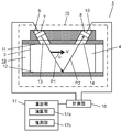
- FIG. 1 is a schematic configuration diagram of an ultrasonic flowmeter according to Embodiment 1 of the present invention.
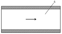
- 2 is a cross-sectional view taken along line 2-2 of FIG. 1 in Embodiment 1 of the present invention.
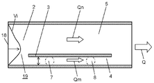
- FIG. 3 is a cross-sectional view taken along line 3-3 of FIG. 1 in Embodiment 1 of the present invention.
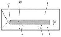
- 4 is a cross-sectional view taken along line 4-4 of FIG. 1 in Embodiment 1 of the present invention.
- FIG. 5 is a cross-sectional view of the ultrasonic flowmeter according to the second embodiment of the present invention.
- FIG. 6 is a cross-sectional view of the ultrasonic flowmeter according to the third embodiment of the present invention.
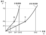
- FIG. 7A is a diagram showing an example of a pressure-flow rate graph according to Embodiment 3 of the present invention.
- FIG. 7B is a diagram showing another example of a graph of pressure-flow rate characteristics according to Embodiment 3 of the present invention.
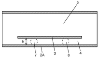
- FIG. 8 is a cross-sectional view of the ultrasonic flowmeter according to the fourth embodiment of the present invention.
- FIG. 9 is a cross-sectional view of an ultrasonic flowmeter according to the fifth embodiment of the present invention.
- FIG. 10 is a diagram showing an example of a pressure-flow rate graph according to Embodiment 5 of the present invention.
- FIG. 11 is a cross-sectional view of an ultrasonic flowmeter according to the sixth embodiment of the present invention.
- FIG. 12 is a cross-sectional view of a conventional ultrasonic flowmeter.
- FIG. 1 is a schematic configuration diagram of the ultrasonic flowmeter according to the first embodiment of the present invention.
- 2 is a cross-sectional view taken along line 2-2 of FIG. 1 in Embodiment 1 of the present invention.
- FIG. 3 is a cross-sectional view taken along line 3-3 of FIG. 1 in Embodiment 1 of the present invention.
- 4 is a cross-sectional view taken along line 4-4 of FIG. 1 in Embodiment 1 of the present invention.
- the ultrasonic flowmeter 1 of the present embodiment measures at least a cylindrical channel 2 having a rectangular cross section and the cylindrical channel 2 along the direction of the flow of the fluid to be measured. From one partition plate 3 that is divided into a flow path 4 and a non-measurement flow path 5, and an ultrasonic transducer holder 6 that holds a pair of ultrasonic transducers provided corresponding to the measurement flow path 4 It is configured.
- the cylindrical flow path 2 may be described simply as the flow path 2.
- the ultrasonic transducer holder 6 includes a pair of ultrasonic transducers including a first ultrasonic transducer 7 and a second ultrasonic transducer 8.
- the first holding unit 9 and the second holding unit 10 hold each of them.
- the measurement channel 4 has an upper surface 11 and a lower surface 12, and a first ultrasonic transmission window 13 and a second ultrasonic transmission window 14 are provided on the upper surface 11 of the measurement channel 4.
- the lower surface 12 of the measurement channel 4 acts as a reflection surface for ultrasonic waves emitted from the first ultrasonic transducer 7 and the second ultrasonic transducer 8.
- the flow rate measuring unit 15 that measures the flow rate and flow velocity of the fluid to be measured from at least the first ultrasonic transducer 7, the second ultrasonic transducer 8, and the lower surface 12 of the measurement flow path 4 is provided. Composed.
- signals received by the first ultrasonic transducer 7 and the second ultrasonic transducer 8 are processed by the measurement unit 16 including a measurement circuit and the like, and the first ultrasonic transducer is processed.
- the propagation time between 7 and the second ultrasonic transducer 8 is measured.
- at least one of the flow rate and the flow velocity of the fluid to be measured flowing through the cylindrical flow path 2 is estimated and calculated by the calculation unit 17a and the estimation unit 17b constituting the calculation unit 17.
- the non-measurement flow path 5 has a member such as a structure or a rectifying member that changes the flow state of the fluid to be measured, as shown in the following embodiments. Is not particularly inserted.
- an upstream portion 19 (flow path from the partition plate 3 to the inlet portion 18) is provided upstream of the partition plate 3.
- the flow of the fluid to be measured flowing from the inlet portion 18 of the cylindrical flow path 2 is once rectified by the running portion 19.
- the rectified fluid to be measured is divided by the partition plate 3, and a part thereof flows into the measurement channel 4 and the rest flows into the non-measurement channel 5.
- the disturbance of the flow of the fluid to be measured in the measurement channel 4 can be suppressed.
- the flow rate and flow rate of the fluid to be measured in the measurement channel 4 can be measured, and the flow rate and flow rate of the fluid to be measured flowing through the cylindrical channel 2 can be accurately estimated over a wide flow rate range and flow rate range. it can.
- the flow velocity and flow rate of the fluid to be measured divided into the measurement flow path 4 is processed via the measurement unit 16 using the propagation time measured by the flow rate measurement unit 15, and the calculation unit of the calculation unit 17 It is calculated by 17a.
- the flow rate and flow rate of the fluid to be measured flowing through the entire tubular channel 2 are calculated by the estimation unit 17b of the calculation unit 17. It can be estimated and calculated.
- the ultrasonic flowmeter 1 of the present embodiment is configured.
- the fluid to be measured that flows into the cylindrical flow path 2 is rectified by the run-up portion 19. Thereafter, the rectified fluid to be measured is divided by the partition plate 3 into two flow paths, a measurement flow path 4 and a non-measurement flow path 5. As a result, the flow rate of the fluid to be measured in the measurement channel 4 is Qm, and the flow rate of the fluid to be measured in the non-measurement channel 5 is Qn.
- the fluid to be measured having a flow rate Qm flowing through the measurement channel 4 passes through the propagation path of the ultrasonic waves radiated from the first ultrasonic transducer 7 and the second ultrasonic transducer 8. At this time, along the propagation path of the ultrasonic wave of the fluid to be measured flowing through the measurement channel 4 from the propagation time of the ultrasonic wave received by the first ultrasonic transducer 7 or the second ultrasonic transducer 8. A flow velocity component is detected. Thereby, the flow velocity or flow rate of the fluid to be measured having the flow rate Qm flowing through the measurement flow path 4 is measured (calculated) using the measurement method described below.
- the flow velocity of the fluid to be measured flowing through the cylindrical flow path 2 is V
- the sound velocity in the fluid to be measured is C
- the flow direction of the fluid to be measured is defined as ⁇ .
- the propagation time t1 until the ultrasonic wave emitted from the first ultrasonic transducer 7 reaches the second ultrasonic transducer 8 is expressed by the following equation (1).
- the measurement unit 16 measures the propagation time t1 and the propagation time t2.
- the calculation unit 17a of the calculation unit 17 calculates the flow velocity V of the fluid to be measured using the above equation (3).
- calculation unit 17a multiplies the calculated flow velocity V by the cross-sectional area S of the measurement flow path 4 and the correction coefficient p to obtain the flow rate Qm of the fluid to be measured in the measurement flow path 4.
- the flow rate Qm obtained as described above is multiplied by a coefficient q for estimating the flow rate of the fluid to be measured flowing through the entire tubular channel 2 by the estimation unit 17b of the calculation unit 17.
- the flow rate Q (Qm + Qn) of the whole cylindrical flow path 2 can be obtained by estimating the flow rate of the fluid to be measured flowing through the entire cylindrical flow path 2.
- the flow to the measurement flow path 4 can be divided by only one partition plate 3 in the cylindrical flow path 2 having a rectangular cross section. it can. Therefore, it is possible to realize a simple and small ultrasonic flowmeter as compared with the conventional ultrasonic flowmeter that forms a large number of divided flows with a large number of partition plates.
- the entire flow rate range of the fluid to be measured measured by the ultrasonic flowmeter is only laminar flow, In the case of only the case, the diversion ratio (Qn / Qm) can be kept relatively constant. As a result, the entire flow rate Q of the fluid to be measured flowing through the cylindrical flow channel 2 can be accurately estimated and obtained based on the flow rate Qm of the measurement flow channel.
- Embodiment 2 an ultrasonic flowmeter according to Embodiment 2 of the present invention will be described with reference to FIG.
- action, etc. as the ultrasonic flowmeter of Embodiment 1 is abbreviate
- FIG. 5 is a cross-sectional view of the ultrasonic flowmeter according to the second embodiment of the present invention.
- FIG. 5 is a cross-sectional view of the ultrasonic flowmeter according to the second embodiment taken along the line 4-4 shown in FIG. 1 in the same manner as FIG. 4 described in the first embodiment.
- the ultrasonic flowmeter of the second embodiment is different from the ultrasonic flowmeter of the first embodiment in that the upstream end 21 of the partition plate 20 has a wedge shape. Since the other components are basically the same as those in the first embodiment, the same reference numerals are used for explanation.
- the partition plate 20 is formed in a triangular shape such as a wedge shape so that the width W of the partition plate 20 becomes narrower on the upstream end 21 side. Thereby, the disturbance of the fluid to be measured at the time of the diversion by the partition plate 20 is suppressed.
- tip part of the partition plate 20 is good also as a shape which has a curvature instead of an edge shape.
- the flow of the fluid to be measured to the measurement channel 4 can be performed at the wedge-shaped tip on the upstream end 21 side of the partition plate 20. Therefore, disturbance of the fluid to be measured flowing into the cylindrical flow path 2 can be suppressed and the flow can be smoothly divided into the measurement flow path 4 and the non-measurement flow path 5. Thereby, the diversion ratio (Qn / Qm) can be kept more constant. As a result, the overall flow rate Q of the fluid to be measured flowing through the cylindrical flow channel 2 can be accurately estimated and obtained based on the flow rate Qm of the measurement flow channel 4.
- Embodiment 3 an ultrasonic flowmeter according to Embodiment 3 of the present invention will be described with reference to FIGS. 6 to 7B.
- action, etc. as the ultrasonic flowmeter of Embodiment 1 is abbreviate
- FIG. 6 is a cross-sectional view of the ultrasonic flowmeter according to the third embodiment of the present invention.
- FIG. 7A is a diagram showing an example of a pressure-flow rate graph according to Embodiment 3 of the present invention.
- FIG. 7B is a diagram showing another example of a graph of pressure-flow rate characteristics according to Embodiment 3 of the present invention.
- FIG. 6 is a cross-sectional view of the ultrasonic flowmeter according to the third embodiment cut along the line 4-4 shown in FIG. 1 in the same manner as FIG. 4 described in the first embodiment.
- the ultrasonic flowmeter according to the third embodiment is different from the ultrasonic flowmeter according to the first embodiment in that a structure 22 including a resistor 22 is disposed in the non-measurement flow path 5. . Since the other components are basically the same as those in the first embodiment, the same reference numerals are used for explanation.
- a resistor 22 made of, for example, a mesh shape or a metal fiber is arranged.
- the fluid to be measured flowing into the measurement channel 4 and the non-measurement channel 5 can be transitioned from laminar flow to turbulent flow with the same pressure difference.
- the flow rate and the pressure difference have a linear (proportional) relationship.
- the flow rate and the pressure difference have a square relationship (non-linear). Therefore, the above relationship can also be applied to the measurement channel 4 and the non-measurement channel 5 in which the cylindrical channel 2 is divided by the partition plate 3.
- FIG. 7A is a graph schematically showing the above relationship. That is, as shown in FIG. 7A, in the measurement channel 4, the flow up to the transition point M is a laminar flow, and the state after the transition point M shows a turbulent flow state. Moreover, in the non-measurement flow path 5, the transition point N is a laminar flow, and after the transition point N, the state of a turbulent flow is shown.
- the diversion ratio (Qn1 / Qm1) is a constant value.
- the measurement flow path 4 and the non-measurement flow path 5 are both in the turbulent flow region, and similarly, the diversion ratio (Qn2 / Qm2) is a constant value. That is, if both the measurement channel 4 and the non-measurement channel 5 are turbulent regions and the flow rate and the pressure difference are in a square relationship, the shunt ratio in turbulent flow and the shunt ratio in laminar flow The value of is the same in each region.
- the diversion ratio (Qns / Qms) is not always a constant value. That is, when the state of the fluid to be measured in the flow rate region is different between laminar flow and turbulent flow, the diversion ratio changes depending on the flow rate flowing through the measurement channel 4 and the non-measurement channel 5. At this time, if the flow rate of the measurement flow path 4 is measured and the flow rate of the entire cylindrical flow path 2 is estimated, it becomes a factor that the measurement accuracy of the flow rate is lowered.
- the measurement flow path 4 and the non-measurement flow path 5 simultaneously shift the resistor 22 constituting the structure from the laminar flow state to the turbulent flow state with the same pressure difference. 5 is arranged.
- the flow volume of the measurement flow path 4 can be measured, and the flow volume of the whole cylindrical flow path 2 can be estimated over the whole flow area
- the entire flow rate of the fluid to be measured flowing through the cylindrical flow channel 2 can be accurately estimated based on the flow rate of the measurement flow channel 4.
- Embodiment 4 an ultrasonic flowmeter according to Embodiment 4 of the present invention will be described with reference to FIG.
- action, etc. as the ultrasonic flowmeter of Embodiment 3 is abbreviate
- FIG. 8 is a cross-sectional view of the ultrasonic flowmeter according to the fourth embodiment of the present invention.
- FIG. 8 is a cross-sectional view of the ultrasonic flowmeter according to the fourth embodiment cut along the line 4-4 shown in FIG. 1 in the same manner as FIG. 4 described in the first embodiment.
- the structure 23 arranged in the non-measurement flow path 5 is made up of a plurality of resistance plates 24 and 25 (two in the present embodiment). It differs from the ultrasonic flowmeter of Embodiment 3 by the point comprised by.
- the other constituent elements are basically the same as those in the third embodiment, and will be described with the same reference numerals.
- a plurality of resistance plates 24 and 25 are arranged in the non-measurement flow path 5 along the direction in which the fluid to be measured flows, for example.
- the fluid to be measured flowing into the measurement channel 4 and the non-measurement channel 5 can be changed from a laminar flow to a turbulent state with the same pressure difference.
- the structure can be configured by the resistance plates 24 and 25 made of, for example, plate members.
- the same effects as those of the third embodiment can be obtained, and an ultrasonic flowmeter that is easy to manufacture and has high productivity can be realized.
- the structure body is configured by two resistance plates.
- the structure is not limited thereto, and the structure body may be configured by one or three or more resistance plates, and measurement is performed. It can be arbitrarily selected according to the flow rate and flow velocity.
- the example in which the resistance plate is arranged along the flow of the fluid to be measured has been described, but the present invention is not limited to this.
- the fluid to be measured flowing through the measurement channel and the non-measurement channel transitions from the laminar flow region to the turbulent region with the same pressure difference, the fluid is measured at a predetermined angle with respect to the flow of the fluid to be measured.
- a resistance plate having an arbitrary shape may be arranged.
- FIG. 9 is a cross-sectional view of the ultrasonic flowmeter according to the fifth embodiment of the present invention.
- FIG. 10 is a diagram showing an example of a pressure-flow rate graph according to Embodiment 5 of the present invention.
- 9 is a cross-sectional view of the ultrasonic flowmeter according to the fifth embodiment cut in the direction of line 4-4 shown in FIG. 1 in the same manner as FIG. 4 described in the first embodiment.
- the ultrasonic flowmeter according to the fifth embodiment has a layer height h of the measurement channel 4 (an outer peripheral wall of the partition plate 3 and the cylindrical channel 2 facing each other across the measurement channel 4). 2A) is different from the ultrasonic flow meter of the first embodiment in that the laminar flow state is maintained at least in the measurement flow channel 4 over the entire measurement flow rate of the ultrasonic flow meter. .
- the layer height h of the measurement flow path 4 is set to a value that maintains the laminar flow state over the entire measurement flow rate of the ultrasonic flowmeter.
- the layer height h of the measurement channel 4 is such that when the channel cross section of the measurement channel 4 is rectangular and the aspect ratio (long side length / short side length) is large, the Reynolds number Re is The short side length corresponding to the layer height h is used as a representative length, and is obtained by the following equation (4).
- Re (h ⁇ Vave) / ⁇ (4)
- Re Reynolds number
- h representative length
- Vave average flow velocity Therefore, if the layer height h of the measurement channel 4 is set based on the equation (4), the fluid to be measured flows in a laminar state be able to.
- the flow of the fluid to be measured in the measurement flow path 4 is a laminar flow until the layer height h of the measurement flow path 4 reaches the entire flow rate region of the fluid to be measured, that is, the maximum measurement flow rate. Set to be.
- the diversion ratio (Qn / Qm) is constant in the entire flow rate region of the fluid to be measured. become.
- the diversion ratio is not constant.
- the flow rate of the fluid to be measured in the measurement channel 4 can be measured in the laminar flow region, an extremely stable value can be obtained.
- the flow rate of the fluid to be measured can be measured in a laminar flow state at least in the measurement flow channel over the entire flow rate region of the fluid to be measured.
- the flow rate of the fluid to be measured can be measured and estimated with high measurement accuracy while maintaining the diversion ratio (Qn / Qm) of the fluid to be measured between the measurement channel and the non-measurement channel.
- Embodiment 6 an ultrasonic flowmeter according to Embodiment 6 of the present invention will be described with reference to FIG.
- action, etc. as the ultrasonic flowmeter of Embodiment 1 is abbreviate
- FIG. 11 is a cross-sectional view of the ultrasonic flowmeter according to the sixth embodiment of the present invention.
- FIG. 11 is a cross-sectional view of the ultrasonic flowmeter according to the sixth embodiment cut along the line 4-4 shown in FIG. 1 in the same manner as FIG. 4 described in the first embodiment.
- the ultrasonic flowmeter of the sixth embodiment is different from the ultrasonic flowmeter of the first embodiment in that a rectifying member 26 is disposed at the inlet portion 18 of the cylindrical flow path 2. Since the other components are basically the same as those in the first embodiment, the same reference numerals are used for explanation.
- the rectifying member 26 is disposed at the inlet 18 of the cylindrical flow path 2 of the ultrasonic flowmeter 1. Thereby, turbulence and drift of the fluid to be measured flowing into the cylindrical flow path 2 are suppressed. Then, it is possible to stabilize the flow of the fluid to be measured to the measurement flow path 4 and the non-measurement flow path 5 and the flow of the fluid to be measured in the measurement flow path 4. As a result, the measurement accuracy such as the flow rate of the fluid to be measured in the measurement channel 4 can be improved.
- the rectifying member by providing the rectifying member, it is possible to realize an ultrasonic flowmeter that measures the flow rate of the fluid to be measured with high measurement accuracy by suppressing the turbulence and drift of the fluid to be measured.
- one partition plate that divides a flow path through which a fluid to be measured flows into a measurement flow path and a non-measurement flow path, and a pair disposed in the measurement flow path
- An ultrasonic transducer a measurement unit that measures the propagation time of the ultrasonic wave that propagates between the pair of ultrasonic transducers, and a calculation unit that calculates the flow rate of the fluid to be measured.
- the calculation unit calculates at least one of a flow velocity and a flow rate of the fluid to be measured in the measurement channel based on the propagation time, and a flow rate of the fluid to be measured in the channel based on the flow velocity or the flow rate in the measurement channel. It has a guess part which guesses.
- the parameters for determining the flow state of the divided flow can be reduced.
- a simple and small ultrasonic flow meter can be realized.
- the shunt ratio (Qn / Qm) can be kept substantially constant (including constant).
- the flow rate of the entire fluid to be measured flowing through the flow path can be accurately estimated as compared to a case where the flow ratio becomes a complicated function and an error is caused by linear approximation.
- the upstream end of the partition plate is formed in a wedge shape.
- the fluid to be measured is divided into the measurement channel and the non-measurement channel at the wedge-shaped tip. Therefore, the fluid to be measured upstream of the partition plate can be smoothly divided into the measurement channel and the non-measurement channel while further suppressing the occurrence of turbulence and the like. Thereby, the diversion ratio (Qn / Qm) can be kept more constant. As a result, the flow rate of the entire fluid to be measured flowing through the flow path can be estimated with higher accuracy.
- the structure is provided for simultaneously changing the fluid to be measured flowing through the measurement flow channel and the non-measurement flow channel to the turbulent flow state.
- the structure is a resistor disposed in the non-measurement flow path.
- the structure is constituted by a resistance plate.
- the resistance plate which comprises a structure can be produced easily.
- the layer height of the measurement channel is set to be laminar at least at the maximum measurement flow rate of the fluid to be measured flowing through the measurement channel.
- the run-up portion is arranged upstream of the partition plate provided in the flow path.
- the rectifying member is arranged at the inlet of the flow path.
- the rectifying member is disposed in the non-measurement flow path.
- the rectifying member is disposed in the run-up portion.
- the installation range of the rectifying member can be arbitrarily arranged.
- the ultrasonic flowmeter excellent in versatility is realizable.
- the ultrasonic flowmeter of the present invention can measure a fluid to be measured with high accuracy, it is useful in various fields of flow measurement, particularly in fields such as a gas meter that is required to be simple and downsized.
Landscapes
- Physics & Mathematics (AREA)
- Fluid Mechanics (AREA)
- General Physics & Mathematics (AREA)
- Electromagnetism (AREA)
- Measuring Volume Flow (AREA)
Abstract
Description
以下、本発明の実施の形態1における超音波流量計について、図1から図4を用いて説明する。
また、第2の超音波送受波器8から出た超音波が、第1の超音波送受波器7に到達するまでの伝搬時間t2は、以下の式(2)で示される。
そして、伝搬時間t1の式(1)と、伝搬時間t2の式(2)から、被計測流体の音速Cを消去すると、以下の式(3)が得られる。
このとき、式(3)から分るように、第1の超音波送受波器7と第2の超音波送受波器8との距離Lと、角度θが既知ならば、伝搬時間t1および伝搬時間t2を用いて、被計測流体の流速Vは、以下の方法により求めることができる。
以下に、本発明の実施の形態2における超音波流量計について、図5を用いて説明する。なお、実施の形態1の超音波流量計と同じ構成要素や作用などの説明は、省略する。
以下に、本発明の実施の形態3における超音波流量計について、図6から図7Bを用いて説明する。なお、実施の形態1の超音波流量計と同じ構成要素や作用などの説明は、省略する。
以下に、本発明の実施の形態4における超音波流量計について、図8を用いて説明する。なお、実施の形態3の超音波流量計と同じ構成要素や作用などの説明は、省略する。
以下に、本発明の実施の形態5における超音波流量計について、図9と図10を用いて説明する。なお、実施の形態1の超音波流量計と同じ構成要素や作用などの説明は、省略する。
ただし、Re:レイノルズ数、h:代表長さ、Vave:平均流速
そのため、計測流路4の層高さhを、式(4)に基づいて設定すれば、被計測流体を層流状態で流すことができる。
以下に、本発明の実施の形態6における超音波流量計について、図11を用いて説明する。なお、実施の形態1の超音波流量計と同じ構成要素や作用などの説明は、省略する。
2 筒状流路(流路)
2A 外周壁
3,20 仕切り板
4,102A 計測流路
5 非計測流路
6 超音波送受波器保持部
7 第1の超音波送受波器
8 第2の超音波送受波器
9 第1の保持部
10 第2の保持部
11 上面
12 下面
13 第1の超音波透過窓
14 第2の超音波透過窓
15 流量計測部
16 計測部
17 算出部
17a 演算部
17b 推測部
18 入口部
19 助走部
21 上流端
22,23 構造体(抵抗体)
24,25 抵抗板(板部材)
26 整流部材
101 円筒基本流路
102 円筒ハニカム構造体(流路分割部材)
103 円形メッシュ
104 超音波ソナー
Claims (10)
- 被計測流体が流れる流路を計測流路および非計測流路に分割する1つの仕切り板と、
前記計測流路に配置した一対の超音波送受波器と、
前記一対の超音波送受波器間を伝搬する超音波の伝搬時間を計測する計測部と、
前記被計測流体の流量を算出する算出部と、を備え、
前記算出部は、前記伝搬時間に基づいて前記計測流路における前記被計測流体の流速および流量の少なくとも一方を演算する演算部と、前記計測流路における前記流速または前記流量に基づいて前記流路における前記被計測流体の前記流量を推測する推測部を有する超音波流量計。 - 前記仕切り板の上流端を楔形状に形成する請求項1に記載の超音波流量計。
- 前記計測流路と前記非計測流路を流れる前記被計測流体を同時に乱流状態に遷移させる構造体を備える請求項1に記載の超音波流量計。
- 前記構造体は、前記非計測流路に配置した抵抗体である請求項3に記載の超音波流量計。
- 前記構造体は、抵抗板で構成される請求項3に記載の超音波流量計。
- 前記計測流路の層高さは、少なくとも前記計測流路を流れる前記被計測流体の最大計測流量において、層流となるように設定される請求項1に記載の超音波流量計。
- 前記流路に設けた前記仕切り板の上流に助走部を配置する請求項1に記載の超音波流量計。
- 前記流路の入口部に整流部材を配置する請求項1に記載の超音波流量計。
- 前記非計測流路に整流部材を配置する請求項1に記載の超音波流量計。
- 前記助走部に整流部材を配置する請求項7に記載の超音波流量計。
Priority Applications (4)
| Application Number | Priority Date | Filing Date | Title |
|---|---|---|---|
| JP2013523823A JP5974307B2 (ja) | 2011-07-13 | 2012-07-09 | 超音波流量計 |
| US14/128,866 US9091575B2 (en) | 2011-07-13 | 2012-07-09 | Ultrasonic flow-meter |
| EP12811957.5A EP2733471B1 (en) | 2011-07-13 | 2012-07-09 | Ultrasonic flow-meter |
| CN201280034493.XA CN103649692B (zh) | 2011-07-13 | 2012-07-09 | 超声波流量计 |
Applications Claiming Priority (2)
| Application Number | Priority Date | Filing Date | Title |
|---|---|---|---|
| JP2011-154546 | 2011-07-13 | ||
| JP2011154546 | 2011-07-13 |
Publications (1)
| Publication Number | Publication Date |
|---|---|
| WO2013008445A1 true WO2013008445A1 (ja) | 2013-01-17 |
Family
ID=47505749
Family Applications (1)
| Application Number | Title | Priority Date | Filing Date |
|---|---|---|---|
| PCT/JP2012/004423 Ceased WO2013008445A1 (ja) | 2011-07-13 | 2012-07-09 | 超音波流量計 |
Country Status (5)
| Country | Link |
|---|---|
| US (1) | US9091575B2 (ja) |
| EP (1) | EP2733471B1 (ja) |
| JP (1) | JP5974307B2 (ja) |
| CN (1) | CN103649692B (ja) |
| WO (1) | WO2013008445A1 (ja) |
Families Citing this family (12)
| Publication number | Priority date | Publication date | Assignee | Title |
|---|---|---|---|---|
| AT516900A1 (de) * | 2015-03-09 | 2016-09-15 | Dr Collin Gmbh | Vorrichtung und Verfahren zum Testen von Werkstoffen |
| JP6368916B2 (ja) * | 2015-04-16 | 2018-08-08 | パナソニックIpマネジメント株式会社 | 流量計測装置 |
| DE102015008146A1 (de) * | 2015-06-24 | 2016-12-29 | Diehl Metering Gmbh | Durchflusszähler |
| USD845804S1 (en) | 2017-10-13 | 2019-04-16 | Great Plains Industries, Inc. | Insertion ultrasonic flow meter |
| USD845805S1 (en) | 2017-10-13 | 2019-04-16 | Great Plains Industries, Inc. | Tee housing for ultrasonic sensor module |
| USD845806S1 (en) | 2017-10-14 | 2019-04-16 | Great Plains Industries, Inc. | Saddle fitting for ultrasonic sensor module |
| JP6982737B2 (ja) * | 2018-09-10 | 2021-12-17 | パナソニックIpマネジメント株式会社 | 超音波流量計 |
| CA3051376C (en) | 2019-08-06 | 2020-04-28 | Surface Solutions Inc. | Methane monitoring and conversion apparatus and methods |
| CN114585884A (zh) * | 2019-11-19 | 2022-06-03 | 松下知识产权经营株式会社 | 超声波流量计 |
| JP7550364B2 (ja) * | 2021-03-25 | 2024-09-13 | パナソニックIpマネジメント株式会社 | 超音波流量計 |
| WO2023048599A1 (en) * | 2021-09-23 | 2023-03-30 | Alexandr Mikhailovich Derevyagin | Device and method for ultrasonic measurement of the fluid flow velocity and flowrate |
| CN117213571A (zh) * | 2023-09-18 | 2023-12-12 | 青岛乾程科技股份有限公司 | 一种提高超声波气体流量计计量误差线性度的结构及方法 |
Citations (4)
| Publication number | Priority date | Publication date | Assignee | Title |
|---|---|---|---|---|
| JP2003185477A (ja) * | 2001-12-21 | 2003-07-03 | Yazaki Corp | 流量計 |
| JP2004251686A (ja) * | 2003-02-19 | 2004-09-09 | Toyo Keiki Co Ltd | 超音波ガスメータを用いたガス流量計測方法 |
| JP2008122106A (ja) * | 2006-11-08 | 2008-05-29 | Matsushita Electric Ind Co Ltd | 超音波式流体計測装置 |
| JP2010066068A (ja) * | 2008-09-09 | 2010-03-25 | Tokyo Gas Co Ltd | 超音波流量計 |
Family Cites Families (12)
| Publication number | Priority date | Publication date | Assignee | Title |
|---|---|---|---|---|
| US5297427A (en) * | 1992-09-03 | 1994-03-29 | Alicat Scientific, Inc. | Wide-range laminar flowmeter |
| US5511416A (en) * | 1993-09-15 | 1996-04-30 | Alicat Scientific, Inc. | Wide range laminar flow element |
| US5837903A (en) * | 1995-09-22 | 1998-11-17 | The Scott Fetzer Company Inc. | Device for measuring exhaust flowrate using laminar flow element |
| US6601460B1 (en) * | 1998-06-10 | 2003-08-05 | Peter Albert Materna | Flowmeter based on pressure drop across parallel geometry using boundary layer flow including Reynolds numbers above the laminar range |
| JP4186645B2 (ja) * | 2003-02-24 | 2008-11-26 | 松下電器産業株式会社 | 超音波流量計測装置 |
| US7237441B2 (en) * | 2003-02-24 | 2007-07-03 | Matsushita Electric Industrial Co., Ltd. | Ultrasonic type fluid measurement device |
| DE10317166A1 (de) * | 2003-04-15 | 2004-11-04 | Abb Research Ltd. | Gaszähleranordnung mit verbesserter Strömungsgeometrie |
| DE102006024363A1 (de) * | 2006-05-24 | 2007-11-29 | Robert Bosch Gmbh | Vorrichtung zur Volumen- oder Fließgeschwindigkeitsmessung von Fluiden |
| US7472610B2 (en) * | 2006-12-08 | 2009-01-06 | Cummins Filtration Ip, Inc | Apparatus, system, and method for differential pressure measurement across a conduit flow area change |
| JP5014178B2 (ja) * | 2008-01-24 | 2012-08-29 | アズビル株式会社 | ガスメータ |
| JP2010117201A (ja) * | 2008-11-12 | 2010-05-27 | Yazaki Corp | 流量計 |
| US9343898B2 (en) * | 2013-07-19 | 2016-05-17 | Texas Instruments Incorporated | Driver current control apparatus and methods |
-
2012
- 2012-07-09 JP JP2013523823A patent/JP5974307B2/ja not_active Expired - Fee Related
- 2012-07-09 WO PCT/JP2012/004423 patent/WO2013008445A1/ja not_active Ceased
- 2012-07-09 US US14/128,866 patent/US9091575B2/en not_active Expired - Fee Related
- 2012-07-09 EP EP12811957.5A patent/EP2733471B1/en not_active Not-in-force
- 2012-07-09 CN CN201280034493.XA patent/CN103649692B/zh not_active Expired - Fee Related
Patent Citations (4)
| Publication number | Priority date | Publication date | Assignee | Title |
|---|---|---|---|---|
| JP2003185477A (ja) * | 2001-12-21 | 2003-07-03 | Yazaki Corp | 流量計 |
| JP2004251686A (ja) * | 2003-02-19 | 2004-09-09 | Toyo Keiki Co Ltd | 超音波ガスメータを用いたガス流量計測方法 |
| JP2008122106A (ja) * | 2006-11-08 | 2008-05-29 | Matsushita Electric Ind Co Ltd | 超音波式流体計測装置 |
| JP2010066068A (ja) * | 2008-09-09 | 2010-03-25 | Tokyo Gas Co Ltd | 超音波流量計 |
Non-Patent Citations (1)
| Title |
|---|
| See also references of EP2733471A4 * |
Also Published As
| Publication number | Publication date |
|---|---|
| US20140230568A1 (en) | 2014-08-21 |
| EP2733471B1 (en) | 2019-03-20 |
| EP2733471A1 (en) | 2014-05-21 |
| JPWO2013008445A1 (ja) | 2015-02-23 |
| EP2733471A4 (en) | 2014-07-16 |
| US9091575B2 (en) | 2015-07-28 |
| CN103649692A (zh) | 2014-03-19 |
| JP5974307B2 (ja) | 2016-08-23 |
| CN103649692B (zh) | 2017-04-05 |
Similar Documents
| Publication | Publication Date | Title |
|---|---|---|
| JP5974307B2 (ja) | 超音波流量計 | |
| JP2014077679A (ja) | 流量計 | |
| CA2702666C (en) | A method and system for detecting deposit buildup within an ultrasonic flow meter | |
| JP6309405B2 (ja) | 超音波流量計及び流量の計測方法 | |
| US7870793B1 (en) | Transit time flow sensor with enhanced accuracy | |
| JP7285450B2 (ja) | 超音波流量計 | |
| CN107709937A (zh) | 测量单元和流量计 | |
| US11549841B2 (en) | Ultrasonic meter employing two or more dissimilar chordal multipath integration methods in one body | |
| JP2895704B2 (ja) | 超音波流量計 | |
| JP2020024149A (ja) | 超音波流量計 | |
| JP7209139B2 (ja) | 超音波流量計 | |
| JP2021117033A (ja) | 差圧式流量計 | |
| JP2020148485A (ja) | 層流素子および層流型流量計 | |
| JP5070620B2 (ja) | 超音波流量計及び流量計測方法 | |
| JP6229144B2 (ja) | 流量計測装置 | |
| JP2013217780A (ja) | 超音波流量計 | |
| KR100935876B1 (ko) | 초음파 유속측정방법 및 초음파 유량측정방법 | |
| JP6496905B2 (ja) | 超音波流量計 | |
| JP2956804B2 (ja) | 超音波流量計 | |
| JP6982737B2 (ja) | 超音波流量計 | |
| JP4604520B2 (ja) | 流れ計測装置 | |
| JP7373772B2 (ja) | 物理量計測装置 | |
| JP2017181230A (ja) | 流量計測装置 | |
| JP4931550B2 (ja) | 超音波流量計 | |
| JP3252187B2 (ja) | 流量計 |
Legal Events
| Date | Code | Title | Description |
|---|---|---|---|
| 121 | Ep: the epo has been informed by wipo that ep was designated in this application |
Ref document number: 12811957 Country of ref document: EP Kind code of ref document: A1 |
|
| ENP | Entry into the national phase |
Ref document number: 2013523823 Country of ref document: JP Kind code of ref document: A |
|
| WWE | Wipo information: entry into national phase |
Ref document number: 2012811957 Country of ref document: EP |
|
| WWE | Wipo information: entry into national phase |
Ref document number: 14128866 Country of ref document: US |
|
| NENP | Non-entry into the national phase |
Ref country code: DE |