WO2013012100A2 - 熱交換器挿通管の掴持体の製造方法及びその掴持体を用いた熱交換器の製造方法並びに製造された熱交換器を有する空気調和機及び/又はその室外機 - Google Patents
熱交換器挿通管の掴持体の製造方法及びその掴持体を用いた熱交換器の製造方法並びに製造された熱交換器を有する空気調和機及び/又はその室外機 Download PDFInfo
- Publication number
- WO2013012100A2 WO2013012100A2 PCT/JP2012/069264 JP2012069264W WO2013012100A2 WO 2013012100 A2 WO2013012100 A2 WO 2013012100A2 JP 2012069264 W JP2012069264 W JP 2012069264W WO 2013012100 A2 WO2013012100 A2 WO 2013012100A2
- Authority
- WO
- WIPO (PCT)
- Prior art keywords
- tube
- heat exchanger
- gripping body
- pipe
- slit
- Prior art date
- Legal status (The legal status is an assumption and is not a legal conclusion. Google has not performed a legal analysis and makes no representation as to the accuracy of the status listed.)
- Ceased
Links
Images






Classifications
-
- B—PERFORMING OPERATIONS; TRANSPORTING
- B23—MACHINE TOOLS; METAL-WORKING NOT OTHERWISE PROVIDED FOR
- B23P—METAL-WORKING NOT OTHERWISE PROVIDED FOR; COMBINED OPERATIONS; UNIVERSAL MACHINE TOOLS
- B23P15/00—Making specific metal objects by operations not covered by a single other subclass or a group in this subclass
- B23P15/26—Making specific metal objects by operations not covered by a single other subclass or a group in this subclass heat exchangers or the like
-
- B—PERFORMING OPERATIONS; TRANSPORTING
- B21—MECHANICAL METAL-WORKING WITHOUT ESSENTIALLY REMOVING MATERIAL; PUNCHING METAL
- B21D—WORKING OR PROCESSING OF SHEET METAL OR METAL TUBES, RODS OR PROFILES WITHOUT ESSENTIALLY REMOVING MATERIAL; PUNCHING METAL
- B21D41/00—Application of procedures in order to alter the diameter of tube ends
- B21D41/02—Enlarging
- B21D41/026—Enlarging by means of mandrels
- B21D41/028—Enlarging by means of mandrels expandable mandrels
-
- B—PERFORMING OPERATIONS; TRANSPORTING
- B21—MECHANICAL METAL-WORKING WITHOUT ESSENTIALLY REMOVING MATERIAL; PUNCHING METAL
- B21D—WORKING OR PROCESSING OF SHEET METAL OR METAL TUBES, RODS OR PROFILES WITHOUT ESSENTIALLY REMOVING MATERIAL; PUNCHING METAL
- B21D53/00—Making other particular articles
- B21D53/02—Making other particular articles heat exchangers or parts thereof, e.g. radiators, condensers fins, headers
- B21D53/08—Making other particular articles heat exchangers or parts thereof, e.g. radiators, condensers fins, headers of both metal tubes and sheet metal
-
- F—MECHANICAL ENGINEERING; LIGHTING; HEATING; WEAPONS; BLASTING
- F28—HEAT EXCHANGE IN GENERAL
- F28F—DETAILS OF HEAT-EXCHANGE AND HEAT-TRANSFER APPARATUS, OF GENERAL APPLICATION
- F28F1/00—Tubular elements; Assemblies of tubular elements
- F28F1/10—Tubular elements and assemblies thereof with means for increasing heat-transfer area, e.g. with fins, with projections, with recesses
- F28F1/12—Tubular elements and assemblies thereof with means for increasing heat-transfer area, e.g. with fins, with projections, with recesses the means being only outside the tubular element
- F28F1/24—Tubular elements and assemblies thereof with means for increasing heat-transfer area, e.g. with fins, with projections, with recesses the means being only outside the tubular element and extending transversely
- F28F1/30—Tubular elements and assemblies thereof with means for increasing heat-transfer area, e.g. with fins, with projections, with recesses the means being only outside the tubular element and extending transversely the means being attachable to the element
-
- F—MECHANICAL ENGINEERING; LIGHTING; HEATING; WEAPONS; BLASTING
- F28—HEAT EXCHANGE IN GENERAL
- F28F—DETAILS OF HEAT-EXCHANGE AND HEAT-TRANSFER APPARATUS, OF GENERAL APPLICATION
- F28F1/00—Tubular elements; Assemblies of tubular elements
- F28F1/10—Tubular elements and assemblies thereof with means for increasing heat-transfer area, e.g. with fins, with projections, with recesses
- F28F1/12—Tubular elements and assemblies thereof with means for increasing heat-transfer area, e.g. with fins, with projections, with recesses the means being only outside the tubular element
- F28F1/24—Tubular elements and assemblies thereof with means for increasing heat-transfer area, e.g. with fins, with projections, with recesses the means being only outside the tubular element and extending transversely
- F28F1/32—Tubular elements and assemblies thereof with means for increasing heat-transfer area, e.g. with fins, with projections, with recesses the means being only outside the tubular element and extending transversely the means having portions engaging further tubular elements
-
- F—MECHANICAL ENGINEERING; LIGHTING; HEATING; WEAPONS; BLASTING
- F28—HEAT EXCHANGE IN GENERAL
- F28D—HEAT-EXCHANGE APPARATUS, NOT PROVIDED FOR IN ANOTHER SUBCLASS, IN WHICH THE HEAT-EXCHANGE MEDIA DO NOT COME INTO DIRECT CONTACT
- F28D1/00—Heat-exchange apparatus having stationary conduit assemblies for one heat-exchange medium only, the media being in contact with different sides of the conduit wall, in which the other heat-exchange medium is a large body of fluid, e.g. domestic or motor car radiators
- F28D1/02—Heat-exchange apparatus having stationary conduit assemblies for one heat-exchange medium only, the media being in contact with different sides of the conduit wall, in which the other heat-exchange medium is a large body of fluid, e.g. domestic or motor car radiators with heat-exchange conduits immersed in the body of fluid
- F28D1/04—Heat-exchange apparatus having stationary conduit assemblies for one heat-exchange medium only, the media being in contact with different sides of the conduit wall, in which the other heat-exchange medium is a large body of fluid, e.g. domestic or motor car radiators with heat-exchange conduits immersed in the body of fluid with tubular conduits
- F28D1/047—Heat-exchange apparatus having stationary conduit assemblies for one heat-exchange medium only, the media being in contact with different sides of the conduit wall, in which the other heat-exchange medium is a large body of fluid, e.g. domestic or motor car radiators with heat-exchange conduits immersed in the body of fluid with tubular conduits the conduits being bent, e.g. in a serpentine or zig-zag
- F28D1/0475—Heat-exchange apparatus having stationary conduit assemblies for one heat-exchange medium only, the media being in contact with different sides of the conduit wall, in which the other heat-exchange medium is a large body of fluid, e.g. domestic or motor car radiators with heat-exchange conduits immersed in the body of fluid with tubular conduits the conduits being bent, e.g. in a serpentine or zig-zag the conduits having a single U-bend
-
- F—MECHANICAL ENGINEERING; LIGHTING; HEATING; WEAPONS; BLASTING
- F28—HEAT EXCHANGE IN GENERAL
- F28F—DETAILS OF HEAT-EXCHANGE AND HEAT-TRANSFER APPARATUS, OF GENERAL APPLICATION
- F28F2255/00—Heat exchanger elements made of materials having special features or resulting from particular manufacturing processes
-
- Y—GENERAL TAGGING OF NEW TECHNOLOGICAL DEVELOPMENTS; GENERAL TAGGING OF CROSS-SECTIONAL TECHNOLOGIES SPANNING OVER SEVERAL SECTIONS OF THE IPC; TECHNICAL SUBJECTS COVERED BY FORMER USPC CROSS-REFERENCE ART COLLECTIONS [XRACs] AND DIGESTS
- Y10—TECHNICAL SUBJECTS COVERED BY FORMER USPC
- Y10T—TECHNICAL SUBJECTS COVERED BY FORMER US CLASSIFICATION
- Y10T29/00—Metal working
- Y10T29/49—Method of mechanical manufacture
- Y10T29/4935—Heat exchanger or boiler making
- Y10T29/49377—Tube with heat transfer means
- Y10T29/49378—Finned tube
Definitions
- the present invention expands the pipe using a pipe gripping body so as to keep the entire length of the pipe inserted into each through hole of the heat dissipating fins of a plurality of superposed heat exchangers substantially the same as before the pipe expansion.
- the outer diameter of the tube is substantially the same as the inner diameter of the gripping body itself or the inner diameter between the abutting members (the inner diameter between the projecting bodies when the projecting body is provided inside the abutting member).
- the expanded portion along the longitudinal direction of the expanded portion mandrel
- the mouth portion of the pipe provided with the pipe expanding portion
- the one described in the former gazette is a heat constructed by inserting a large number of hairpin tubes 7 through a large number of radiating fins 6 polymerized at a predetermined interval.
- the hairpin portion 7c of the hairpin tube 7 is connected to the tube.
- the mandrel 2 for tube expansion is inserted from the tube opening part 7b of the hairpin tube 7, and the tube opening part 7b side rather than the radiation fin 6 on one end side
- the expanded portion 7d is fixed in the through-hole 9 of the clamp 8 that does not move to the hairpin portion 7c, and the subsequent insertion of the expansion mandrel 2 into the hairpin tube 7 is performed by the clamp body. 8 to fix the hairpin tube 7 fixing part Restrained without moving to the down portion 7c side, a method of performing in a state of being restrained without and moving the fixed portion of the hairpin tube 7 by the hook member 10 to the tube opening 7b.
- the hairpin tube 7 closer to the tube opening 7b than the radiating fin 6 in the hairpin tube 7 is fixed in the through hole 9 of the clamp body 8, and this fixed portion is restrained without moving toward the hairpin portion 7c.
- the hairpin tube 7 tends to contract during expansion through the insertion of the tube expansion mandrel 2, but since the hairpin portion 7c is also restrained by the hook body 10, the contraction of the hairpin tube 7 7 is prevented by reducing the wall thickness, and as a result, the contraction of the total length of the pipe after the expansion can be minimized.
- the heat exchanger manufacturing method according to the above method has the following problems.
- the tube port portion 7 b of the hairpin tube 7 is fixed in the through hole 9 of the clamp 8, so that it is inserted into the radiating fins 6 in a zigzag manner, for example.
- the number of hairpin tubes 7 is three rows, four rows, and a plurality of rows, the hairpin tubes 7 located on the inner side cannot be fixed by the clamps 8.
- the above problem can be solved by mechanically changing the diameter of the through hole 9 of the clamp 8 by the throttle mechanism.
- the interval between the hairpin tubes 7 is complicated. If the distance between the adjacent mechanisms is smaller than the distance between the adjacent mechanisms, it cannot be used at all due to the problem of the installation space of the diaphragm mechanism.
- 1c represents a mounting table for the heat exchanger 5 erected on the base 1b.
- a plurality of superposed radiating fins 6 are provided in the heat exchanger 5.
- a plurality of hairpin tubes 7 having a predetermined length are inserted in a row (not shown) in a direction along the surface of the mounting table 1c, and the heat exchanger 5 is mounted above the mounting table 1c.
- a pressing plate 11 for pressing and fixing to the mounting table 1c is provided to be movable up and down.
- Reference numeral 2 denotes a tube expansion mandrel provided on the apparatus main body 1a in a substantially horizontal state so as to be reciprocally movable.
- the tube expansion mandrel 2 is opposed to the tube expansion mandrel 2 as shown in FIGS. 2 (a) and 2 (b).
- a plurality of tubes that are formed with an inclined surface 3b that is inclined in a direction that expands toward the tube opening 7b side of the tube 7 that is to be radially expanded and contracted (arrow E) in a direction that intersects the longitudinal direction of the hairpin tube 7.
- a gripping body 3 having a contact member 3f is externally fitted so as to be reciprocally movable, and the inclined surface 3b is formed so as to reach the tip of the tube contact member 3f.
- a male screw portion 3k provided on the other end opposite to the tube contact member 3f can be reciprocated at a predetermined pitch in the longitudinal direction of the hairpin tube 7 via reciprocating means such as a cylinder (not shown) (arrow) F) and is held by being screwed onto the gripper holding member 3l.
- the gripping body 3 is connected to a guide tube holding member 3d which can reciprocate (arrow G) via a reciprocating means such as a cylinder (not shown), and a male screw portion 3h provided at the other end.
- a gripping body guide cylinder 3c that is screwed and held is slidably fitted outside.
- Each of the tube contact members 3f of the gripping body 3 may be four (for example, six, for example) so as to surround the outer periphery of the mandrel 2 along the longitudinal direction of the tube expansion mandrel 2.
- the optimum number of sheets may be set according to the diameter.
- the gripping body guide cylinder 3c is provided between the pipe contact members 3f via the guide cylinder holding member 3d.
- the gripping body guide cylinder is provided with an inclined surface 3b which is provided on the outer peripheral surface of each of the tube contact members 3f and which is inclined in a direction extending toward the tube opening 7b of the opposing tube 7 when it is advanced to the side.
- the inner surface of 3c slides while being pressed down in the axial direction of the hairpin tube 7, so that each of the tube contact members 3f is slit-shaped with a predetermined width dimension 3u for reducing the diameter radially in the axial direction of the mandrel 2.
- the gap 3a has a certain length along the longitudinal direction of the hairpin tube 7. It has a structure having a so-called collet chuck mechanism, which is formed at regular intervals at four locations (not necessarily at four locations, which is proportional to the set number of tube contact members 3f).
- a plurality of gripping bodies 3 having tube abutting members 3f are provided in the direction along the surface of the mounting table 1c to face the individual tube opening portions 7b of the hairpin tubes 7 inserted through the heat exchanger 5 (see FIG. Not shown).
- 1 shows a sandwiching body moving device composed of a guide rail 12 that reciprocates and a reciprocating cylinder 4f that allows the base table 4d to reciprocate, and the pair of sandwiching bodies 4a are inserted into the radiating fins 6 of the heat exchanger 5.
- a plurality (not shown) are provided in the direction along the surface of the mounting table 1c to face the hairpin portion 7c of each hairpin tube 7 that has been made.
- the heat exchanger manufacturing apparatus 1 using the gripping body 3 of the heat exchanger insertion tube having the above-described configuration is used to press-fit the mandrel 2 for expanding the tube into the hairpin tube 7 of the heat exchanger, thereby manufacturing the heat exchanger 5.
- the heat exchanger 5 is placed on the mounting table 1c, and then the pressing plate 11 positioned above is lowered to place the heat exchanger 5 on the mounting table. Press and fix between 1c.
- the hairpin portion 7c of the hairpin tube 7 of the heat exchanger 5 is moved forward (not shown) along the guide rail 12 by operating the reciprocating cylinder 4f of the sandwiching body moving device 4 and The drive cylinder 4e is driven to hold the hairpin portions 7c of the hairpin tubes 7 by the substantially tongue-shaped concave portions 4g in a plan view of the pair of sandwiching bodies 4a as shown in FIG.
- the inner surface of the substantially tongue-shaped concave portion 4g in plan view facing the sandwiching body 4a goes around to the substantially U-shaped inner peripheral surface portion of the hairpin portion 7c.
- the substantially U-shaped inner peripheral surface portion is provided with a convex portion 4c having a generally tongue shape in plan view that prevents movement in the contraction direction.
- each expansion mandrel 2 is press-fitted at a predetermined depth (arrow A) from the tube opening 7b of each hairpin tube 7 to form an expansion portion 7d having a predetermined length.
- the peripheral surface portion 7e is moved forward (arrow B) to the peripheral surface portion 7e of the expanded tube portion 7d from the tube port portion 7b side of the hairpin tube 7 via the gripping body holding member 3l.
- the gripping body 3 is externally fitted in a surrounding state by a plurality of tube contact members 3f that can be expanded and contracted.
- the holding body guide cylinder 3c is provided on the outer surface of each of the tube abutting members 3f and presses while sliding on an inclined surface 3b that is inclined in the direction of expanding toward the tube opening 7b of the opposite tube 7.
- Each of the tube abutting members 3f is reduced in diameter to a space distance of a predetermined width dimension 3u of the slit-shaped gap 3a, that is, an anti-radial shape in the axial center direction of the tube expansion mandrel 2.
- the member 3f firmly holds and holds the peripheral surface portion 7e of the expanded portion 7d of the hairpin tube 7.
- the tube expansion mandrel 2 is held in a state where the peripheral surface portion 7e of the tube expansion portion 7d in the vicinity of the tube opening portion 7b of the hairpin tube 7 is firmly held via the plurality of tube contact members 3f of the holding body 3.
- the sandwiching body moving device 4 having the sandwiching body 4a sandwiching the hairpin portion 7c is slightly moved in the same direction as the forward direction of the tube expansion mandrel 2 ( By retracting (not shown) and applying a tensile force to the entire hairpin tube 7, not only the entire length of the hairpin tube 7 is contracted but also the sliding of the hairpin tube 7 from the tube contact member 3f and the sandwiching body 4a. Therefore, it is possible to manufacture a heat exchanger in which the shrinkage of the entire length of the hairpin tube 7 is further minimized, and as a result, it is possible to manufacture a heat exchanger in which the material cost is minimized. I can do it.
- each holding body 3 having a plurality of tube contact members 3f that advance from the direction of the tube opening 7b of the hairpin tube 7 can be fixed individually.
- each of the tube contact members 3f of the gripping body 3 is Since the peripheral surface portion 7e of the tube expansion portion 7d of the hairpin tube 7 is gripped by reducing the diameter thereof in an anti-radial manner through the slit-shaped gap 3a having a predetermined width 3u provided between the tube contact members 3f. Even if there is a slight difference in the tube diameter, the tube opening of the hairpin tube 7 is securely and firmly adjusted through the spatial distance of the slit-shaped gap 3a having a predetermined width 3u between the tube contact members 3f.
- the hook body 10 In addition to being able to hold the portion 7b side, also in the hairpin portion 7c, the hook body 10 having a shape that matches the arc shape substantially the same as the inner periphery of the hairpin portion 7c, which differs for each tube diameter of the hairpin tube 7. , Expand the tube by exchanging it for each tube diameter of the hairpin tube 7 Because there is no need for any inconvenience, it is possible to hold the pin in a close contact state through the pair of holding members 4a without deforming the arc shape of the hairpin portion 7c of the hairpin tube 7, so that it can be securely and firmly held.
- the heat exchanger A desired tube expansion can be applied to the heat exchanger without any modification to the manufacturing apparatus.
- the hairpin tube is connected to the radiating fin 6 of the heat exchanger 5.
- 7 is inserted in a zigzag pattern (not shown) as described above, and each hairpin tube 7 inserted in a zigzag pattern is inserted into a plurality of rows of three or four rows so as to make the interval (insertion pitch) close to each other.
- the width (separation distance) between the facing tubes of the hairpin tube 7 and the length of protrusion from the end side radiation fin 6 of the hairpin portion 7c of the hairpin tube 7 are considered.
- the hairpin tube 7 does not necessarily have to be inserted into the heat radiating fins 6 of the heat exchanger 5, for example, even when a large number of straight tubes (not shown) are inserted into the heat radiating fins 6 of the heat exchanger 5, One end of the straight pipe projecting from the end-side radiating fin 6 is sandwiched and held by the pair of sandwiching bodies 4a, and thereafter, the mandrel 2 for expanding the tube from the tube opening 7b on the other end side of the straight pipe is the same as described above. By press-fitting through the process, a high-quality heat exchanger with high dimensional accuracy can be produced.
- the tube for expanding the tube is also used. Even if the tube diameter is slightly different depending on the type of heat exchanger specifications, the hairpin tube or straight tube located on the inner side is as strong and strong as the hairpin tube or straight tube located on the outer side. It is possible to hold and expand pipes, and to produce high-quality heat exchangers that minimize material costs by minimizing the shrinkage of the overall length. .
- the peripheral surface portion 7e of the gripped expanded tube portion 7d is pressed (arrow D) to each of the tube contact members 3f at positions where they contact the hairpin tube 7 and the expanded tube portion 7d.
- the tube expansion portion 7d is more firmly formed.
- the problems to be solved by the present invention are as follows. That is, according to the heat exchanger manufacturing apparatus 1 having the above-described configuration, the inclined surface 3b that is inclined in the direction that expands toward the tube opening 7b side of the opposing tube 7 is formed, and the longitudinal direction of the hairpin tube 7 is A gripping body 3 having a plurality of pipe contact members 3f that are radially expandable / retractable (arrow E) in an intersecting direction can be externally fitted in a reciprocating manner from a pipe opening 7b of the pipe 7, and the inclined surface 3b
- the gripping body 3 is formed so as to reach the tip 3o of the tube contact member 3f, and the male screw portion 3k provided on the other end side opposite to the tube contact member 3f is disposed in the longitudinal direction of the hairpin tube 7.
- a reciprocating means such as a cylinder (not shown) or the like is screwed to and held by a gripping body holding member 3l that can reciprocate at a predetermined pitch (arrow F).
- Reciprocating (arrow G) via reciprocating means such as (not shown) Since a gripper guide cylinder 3c that is screwed and held via a male screw part 3h provided at the other end is slidably fitted to the id cylinder holding member 3d, the guide cylinder 3c is By sliding the tube abutting member 3f toward the tube port 7b side of the tube 7 along the inclined surface 3b, the diameter of each of the tube abutting members 3f is reduced radially, while the tube abutting member 3f.
- the tip of the guide tube 3c becomes the tip 3o of the tube abutting member 3f. It is necessary to advance the guide cylinder 3c while sliding it on the inclined surface 3b of the pipe contact member 3f to reach the position.
- the holding body 3 of Each of the tube contact members 3f has a certain distance between the peripheral surface portion 7e of the expanded portion 7d of the hairpin tube 7 via the spatial distance of the slit-shaped gap 3a having a predetermined width dimension 3u provided between the tube contact members 3f. Since the gripping is carried out while adjusting, the diameter of the tube diameter is automatically adjusted via the slit-like gap 3a between the respective tube contact members 3f, so that the tube opening of the hairpin tube 7 is surely and firmly established.
- the inclined surface 3b of the tube contact member 3f is the tube contact member. Since it is formed to a position that reaches the tip 3o of 3f, When the diameter of the abutting member 3f is reduced, the tip of the gripper guide cylinder 3c must be moved to the position of the tip 3o of the tube abutting member 3f. Even when the outer diameter of 3 itself is made as small as necessary, the outer diameter dimension of the gripping body guide cylinder 3c to be externally fitted is always up to the tip 3o of the opposing pipe contact member 3f that is reduced in diameter when expanded.
- each straight tube or each hairpin tube 7 With a significantly narrow interval is held by the gripping body guide tube.
- a gripping body 3 having a simple structure in which the grasping body guide cylinder 3c is slidably reciprocated on the tube abutting member 3f toward the tube opening 7b.
- the interval between the straight pipes and the hairpin pipes 7 inserted through the radiation fins 6 is extremely narrow. Even in such a case, the gripping body 3 that can avoid the contact of the gripping body guide tube 3c located next to the gripping body 3 and can significantly reduce the interval (pitch), and the heat exchange having the gripping body 3 Development of a container manufacturing device has been desired.
- the outer diameter of the expanded portion of the pipe is the gripping body 3 or the gripping body 3. If it is smaller than the inner diameter between the tube abutting members 3f, there is no problem in fitting the gripping body 3 or the tube abutting member 3f to the peripheral surface portion 7e of the straight tube or the expanded portion 7d of each hairpin tube 7.
- the outer diameter of the expanded portion of the tube is substantially the same as the inner diameter between the gripping body 3 and the tube contact member 3f of the gripping body 3 (the inner diameter between the protrusions 3e when the projection body 3e is provided).
- the axial center direction of the expanded tube portion 7d along the longitudinal direction of the mandrel of the expanded tube portion 7d is slightly inclined so as to deviate from the axial direction of the gripping body 3 along the longitudinal direction of the mandrel.
- the tube opening 7b of the tube provided with the expanded portion 7d and the tip 3o of the tube contact member 3f are in contact with or in contact with each other. Even sometimes deformed or damaged either, some improvements were necessary.
- the present invention reduces the distance between straight tubes and hairpin tubes that are reduced in size by using energy savings and reducing costs (by using thin tubes or reducing the size of the heat exchanger itself) and inserted into the heat radiating fins of the heat exchanger.
- the straight tubes and hairpin tubes are inserted into the radiating fins in multiple rows such as three rows, four rows, etc.
- the outer diameter of the expanded portion of the tube is the inner diameter of the gripping body itself or the inner diameter between the contact members (if a protrusion is provided, Even when the diameter is almost the same as the inner diameter between the protrusions, Even when the axial center direction of the pipe expansion section along the hand direction is slightly inclined so as to be shifted from the axial center direction of the gripping body along the longitudinal direction of the mandrel, the pipe expansion section is to solve all the above problems. Not only can the tube mouth portion of the tube provided with the tip of the tube abutting member of the tube gripper be in contact with or contact with each other to reliably prevent deformation or breakage of at least one of them.
- the present invention takes the following means to solve the above-mentioned problems. That is, the invention according to claim 1 is used in the heat exchanger manufacturing apparatus (1), and the pipe opening (7b) of the pipe (7) inserted into the heat radiating fin (6) of the heat exchanger (5).
- a plurality of tube abutting members (3f) that can be reciprocally fitted to a tube expansion mandrel (2) that can be press-fitted from the outside and that can be radially expanded and contracted in a direction intersecting the longitudinal direction of the tube (7).
- an inclined surface (3b) is formed on the outer surface of the tube abutting member (3f) so as to be inclined toward the tube opening (7b) side of the opposing tube (7).
- a heat exchanger insertion tube that radially expands and contracts each of the tube abutting members (3f) via sliding means that reciprocally slides the inclined surface (3b) of the abutting member (3f) in the longitudinal direction of the tube. It is a manufacturing method of a holding body (3), Comprising: From the other end side of the holding body (3) which has predetermined
- a bulging portion (3z) that bulges in the axial direction of the gripping body (3) so as to form an inner diameter smaller than the inner diameter of the gripping body, and after the bulging portion (3z) is formed,
- a plurality of tube abutting members (3f) that can be radially expanded and contracted in the direction intersecting the longitudinal direction of the tube (7) on the holding body (3), the other end from the one end side of the holding body (3)
- the plurality of slit-shaped gaps (3a) By forming a plurality of slit-shaped gaps (3a) with a predetermined width dimension (3u) along the longitudinal direction of the gripping body (3) to the side, the plurality of slit-shaped gaps (3a)
- the protrusion (3e) protruding in the axial direction of the gripping body (3) by dividing the bulging part (3z) into the number of slit-shaped gaps (3a) via Forming the plurality of pipe contact members (3f) and the slit-shaped gap (3a) from the predetermined
- the object is to manufacture a gripping body (3) having a plurality of tube abutting members (3f) having protrusions (3e) protruding in the core direction.
- the invention according to claim 2 is press-fitted from the tube opening (7b) of the tube (7) used in the heat exchanger manufacturing apparatus (1) and inserted into the heat radiating fin (6) of the heat exchanger (5).
- a plurality of tube abutting members (3f) that can be reciprocally fitted to a possible tube expansion mandrel (2) and that can radially expand and contract in a direction intersecting the longitudinal direction of the tube (7);
- an inclined surface (3b) is formed on the outer surface of the pipe contact member (3f) so as to be inclined toward the tube opening (7b) side of the opposite pipe (7).
- Grasping the heat exchanger insertion tube that radially expands or contracts each of the tube contact members (3f) through sliding means that reciprocally slides the inclined surface (3b) of the member (3f) in the longitudinal direction of the tube
- a body (3) Comprising: From the other end side of a holding body (3) to the one end side used as the pipe mouth part (7b) side direction of a pipe
- An inclined surface (3 m) inclined in a direction expanding toward the tube mouth portion (7b) side of the opposing pipe (7) is cut on the inner peripheral surface of the tip (3o) on one end side of the gripping body (3).
- the gripping body may be formed by the step of forming by grinding and the gripping body (3) to form a plurality of pipe contact members (3f) that are radially expandable / contractable in a direction intersecting the longitudinal direction of the pipe (7).
- a slit-like gap (3a) having a predetermined width dimension (3u) is duplicated with a predetermined length dimension along the longitudinal direction of the gripping body (3) from one end side to the other end side of (3).
- the bulging part (3z) is divided into the number of slit-like gaps (3a) via the plurality of slit-like gaps (3a) and protrudes in the axial direction of the gripping body (3).
- a third aspect of the present invention is the method of manufacturing the gripping body (3) according to the first or second aspect, wherein the slope is inclined in the direction of expanding toward the tube opening (7b) of the opposing pipe (7).
- the surface (3b) is formed by cutting or polishing the outer peripheral surface of the gripping body (3) before forming the slit-shaped gap (3a) having a predetermined width dimension (3u).
- each of the slit-shaped gaps (3a) extends from a predetermined position to the pipe of the pipe (7). It is provided on the outer surface of each pipe contact member (3f) by enlarging the predetermined width dimension (3u) toward the mouth portion (7b) so as to have an enlarged width dimension (3x).
- the degree of inclination of the inclined surface (3b) inclined in the direction of expanding toward the tube opening (7b) side of the opposing pipe (7) is determined from the degree of inclination of the inclined surface (3b) when the slit-shaped gap (3a) is formed.
- the large forming step is inserted into a substantially conical jig or a slit-like gap (3a) having a predetermined width dimension (3u) that is press-fitted from one end side to the other end side of the gripping body (3).
- a rod-shaped jig provided with a plurality of sharp convex bodies as much as possible.
- Invention of Claim 5 is a manufacturing method of the heat exchanger using the holding body of the heat exchanger insertion pipe manufactured by the manufacturing method in any one of the said Claim 1 thru
- the hairpin part of the hairpin tube inserted into the heat radiating fin of the heat exchanger is clamped by the clamp body to restrict the movement in the direction of the tube mouth, or the hairpin part of the hairpin tube inserted into the heat radiating fin of the heat exchanger is hairpinned.
- a mandrel for tube expansion is press-fitted at a predetermined depth from the tube mouth portion of the hairpin tube.
- the gripping body of the heat exchanger insertion tube provided with a plurality of pipe abutting members that can be expanded and contracted radially so as to have an enlarged width dimension that is gradually expanded from the predetermined width dimension is externally fitted to the expanded portion in an enclosed state.
- the pipe abutting members are expanded to gradually reduce the enlarged width dimension of the slit-shaped gap from the predetermined position through the sliding means that presses while sliding toward the tube opening side.
- a third step in which the diameter of the mandrel is reduced in the axial direction of the mandrel and the peripheral surface portion of the expanded portion of the tube is firmly gripped and held via the protrusion of each tube contact member via each tube contact member; The peripheral surface of the expanded portion of the tube is expanded in a state in which it is firmly gripped and held by the protrusions of the tube abutting members of the gripping body. From the fourth step of integrating the heat radiating fin and the tube by press-fitting to the further pipe to use mandrels to produce heat exchanger.
- Invention of Claim 6 is providing the air conditioner provided with the heat exchanger manufactured by the manufacturing method of the said Claim 5.
- the invention described in claim 7 is to provide an outdoor unit having an air conditioner equipped with a heat exchanger manufactured by the manufacturing method described in claim 5.
- the present invention is for use in a heat exchanger manufacturing apparatus (1) and for pipe expansion that can be press-fitted from a pipe opening (7b) of a pipe (7) inserted through a radiating fin (6) of a heat exchanger (5).
- a plurality of pipe abutting members (3f) that can be externally fitted to the mandrel (2) so as to be reciprocally movable and radially expand and contract in a direction intersecting the longitudinal direction of the pipe (7);
- On the outer surface of the contact member (3f) there is formed an inclined surface (3b) that is inclined in a direction expanding toward the tube opening (7b) side of the opposing tube (7), and the tube contact member (3f).
- the heat exchanger insertion tube gripping body (3) that radially expands and contracts each of the tube contact members (3f) through sliding means that reciprocally slides on the inclined surface (3b) in the longitudinal direction of the tube.
- One end of the holding body (3) having a predetermined overall length from the other end side toward the tube opening (7b) side of the pipe (7)
- an inner diameter smaller than the inner diameter of the gripped gripping body (3) is provided in the vicinity of one end of the gripping body (3).
- the gripping body (3) is gripped from one end side to the other end side.
- a plurality of slit-shaped gaps (3a) having a predetermined width dimension (3u) along the longitudinal direction of the body (3) with a predetermined length dimension, the bulges are formed via the plurality of slit-shaped gaps (3a).
- a plurality of tube holders provided with projections (3e) that divide the protruding portion (3z) into the number of slit-shaped gaps (3a) and project in the axial direction of the gripping body (3)
- the step of forming the member (3f), and the predetermined width dimension (3u) is gradually enlarged from the predetermined position toward the tube opening (7b) of each of the slit-shaped gaps (3a).
- the opposing tube (7) provided on the outer surface of each tube abutting member (3f) by expanding to have the expanded width dimension (3x).
- the gripping body (3) having a plurality of pipe contact members (3f) provided with the protrusions (3e) is manufactured, the gripping body (3) manufactured by such a manufacturing method can be When the pipe contact member (3f) is externally fitted from the pipe opening (7b) side of (7), the pipe (7 ) To hold the maximum opening diameter (3y) and the expansion / contraction range of each tube contact member (3f) facing the tube opening (7b) of the tube contact member (3f).
- Each of the slit-shaped gaps (3a) is determined based on the maximum opening diameter and the amount of expansion / contraction range of each tube contact member (3f) through a slit-shaped gap (3a) having a predetermined width dimension (3u) provided in the longitudinal direction of the tube.
- a plurality of pipe contact members (3f) that are radially expandable / contractible of the gripping body (3) are provided so that the slit-shaped gap (3a) is provided from a predetermined location.
- Each pipe contact member (3f) is formed to have an enlarged width dimension (3x) obtained by gradually enlarging the predetermined width dimension (3u) toward the pipe mouth portion (7b) of the pipe (7).
- the slope of the inclined surface (3b) inclined in the direction of expanding toward the tube opening (7b) side of the opposing tube (7) is the inclined surface when the slit-shaped gap (3a) is formed.
- (3b) can be formed larger than the degree of inclination.
- the pipe abutting member (3f) can be moved from the maximum opening diameter (3y) to the minimum opening diameter (outside the expanded portion of the pipe) in proportion to the sliding distance of the guide tube (3c).
- the axial direction of the tube (7) is provided on the inner surface of the gripping body (3) on the side of the tube opening (7b) of the tube contact member (3f).
- the protrusion (3e) protruding to the side cuts the inside of the gripping body (3) with a predetermined depth from the other end side of the gripping body (3) to the one end side.
- a bulging portion (3z) that bulges in the axial direction of the gripping body (3) so as to form an inner diameter smaller than the inner diameter of the gripped gripping body (3).
- the forming step and before forming the bulging site (3z) or after forming the bulging site (3z), are opposed to the inner peripheral surface of the tip (3o) on one end side of the gripping body (3).
- a step of forming an inclined surface (3m) inclined in a direction expanding toward the tube opening (7b) side of the tube (7) by cutting or polishing, and a longitudinal direction of the tube (7) on the gripping body (3) Intersect In order to form a plurality of tube abutting members (3f) that are radially expandable and contractable in the direction from the one end side to the other end side of the gripping body (3) along the longitudinal direction of the gripping body (3).
- the bulging site (3z) is formed into slit-like gaps (3a) via the plurality of slit-like gaps (3a).
- Is divided into the number of tube abutting members (3f), the protrusion dimension (height dimension) of the protrusion 3e itself and the total length of the protrusion (3e) itself (the gripping body (3 ), The length of the protrusion (3e) along the axial direction)) can be easily formed by cutting according to the type, material, etc. of the pipe to be expanded.
- the inclined surface (3b) inclined in a direction expanding toward the tube opening (7b) side of the opposing pipe (7) forms a slit-like gap (3a) having a predetermined width dimension (3u). Since the outer peripheral surface of the gripping body (3) is formed by cutting or polishing before, the gripping body is free of slit-like gaps (3a) during cutting or polishing, that is, without bending. There is an effect that the inclined surface (3b) with high accuracy can be formed on the outer peripheral surface of (3).
- the present invention provides an enlarged width dimension (3u) in which the predetermined width dimension (3u) is gradually enlarged from the predetermined position toward the tube opening (7b) of each of the slit-shaped gaps (3a).
- 3x) is provided so as to have an inclined surface that is provided on the outer surface of each tube abutting member (3f) and is inclined in a direction that expands toward the tube opening (7b) side of the opposite tube (7).
- the step of forming the inclination degree of 3b) larger than the inclination degree of the inclined surface (3b) at the time of forming the slit-like gap (3a) is press-fitted from the one end side of the gripping body (3) toward the other end side.
- each of the inclined surfaces is formed by using a substantially conical jig or a rod-shaped jig having a plurality of sharp convex bodies to be inserted into the slit-shaped gaps (3a) having respective predetermined width dimensions (3u).
- each slit-like gap (3a) is provided. There is an effect that can be spread in equal.
- the heat exchanger manufacturing method using the heat exchanger insertion tube gripping body manufactured by the above manufacturing method includes clamping the hairpin portion of the hairpin tube inserted through the heat radiating fin of the heat exchanger with the clamp body. To restrict the movement in the direction of the tube mouth, or to connect the hairpin portion of the hairpin tube inserted through the heat radiating fin of the heat exchanger with a locking body that can be moved back and forth in the direction intersecting the longitudinal direction of the hairpin tube.
- a first step of forming a predetermined expanded portion by press-fitting a tube expansion mandrel at a predetermined depth from the mouth portion of the hairpin tube after regulating lateral movement, and a reciprocating direction of the tube expansion mandrel A plurality of slit-shaped gaps of a predetermined width dimension provided in the longitudinal direction along the slit, and the slit-shaped gaps gradually increase the predetermined width dimension from a predetermined position toward the tube opening portion of the tube. Released to have the expanded width
- a plurality of tube contact members (3f) having protrusions (3e) projecting in the axial direction of the gripping body (3) are formed, and each of the slit-shaped gaps (3a) is formed from a predetermined position.
- each pipe contact member (3f) is expanded.
- the slope of the inclined surface (3b) when the slit-like gap (3a) is formed is determined by the degree of inclination of the inclined surface (3b) that is provided on the outer surface and is inclined in the direction of expanding toward the tube opening (7b) side of the opposing tube (7).
- the tube contact portion from the tube mouth portion (7b) side of the tube (7) To be larger than the inclination degree of the tube (7), the tube contact portion from the tube mouth portion (7b) side of the tube (7)
- the maximum opening diameter (3Y) and the expansion / contraction range amount of each pipe contact member (3f) facing the pipe opening (7b) of the pipe (7) The maximum of each pipe contact member (3f) through a slit-like gap (3a) having a predetermined width dimension (3u) provided in the longitudinal direction of the gripping body (3) to form the contact member (3f) Therefore, the outer diameter (7i) of the expanded portion (7d) on the side of the opening (7b) of the tube (7) is the inner diameter of the gripping body (3) itself.
- the present invention provides a case where the tube diameter of the hairpin tube (7) of the heat exchanger (5) for expanding the tube varies depending on the type of specification of the heat exchanger (5).
- each of the pipe abutting members (3f) of the gripping body (3) is automatically adapted to fit the pipe diameter via the slit-like gap (3a) provided between the pipe abutting members (3f).
- the protrusion (3e) provided on the tube contact member (3f) is adjusted so that the peripheral surface portion (7e) of the tube expansion portion (7d) formed on the tube mouth portion (7b) side of the hairpin tube (7).
- each pipe contact member (3f) when the diameter of each pipe contact member (3f) is reduced, the gripper guide cylinder (3c) is moved in the direction toward the pipe opening (7b). The diameter reduction of each of the tube contact members (3f) can be completed until the gripper guide tube (3c) reaches the tip (3o) of the tube contact member (3f).
- the outer diameter dimension (3q) of the gripping body guide tube (3c) fitted on the gripping body (3) having the tube abutting member (3f) is set via the slit-shaped gap (3a) when the pipe is expanded.
- the reference diameter (the inner diameter of the gripper guide cylinder (3c)) is the reference diameter (3n) of the distance between the tops of the inclined surfaces (3b) of the opposing pipe contact member (3f) having a reduced diameter.
- the tube expansion member (3f) has a tube expansion portion (3s) that becomes the outer diameter (3n) when the diameter of the tube contact member (3f) is reduced.
- the gripping body guide tube (3c) When fitted, the gripping body guide tube (3c) whose outer diameter dimension (3q) is reduced can avoid the contact of each gripping body guide tube (3c) located next to it, thus saving energy.
- Radiation fins not only in the interval of the hairpin tube (7) but also in each of the straight tube and each hairpin tube in multiple rows such as 3 rows and 4 rows Inserted through by spacing the tubes 6) is an effect that significantly narrowed the heat exchanger (5) can be favorably manufactured.
- FIG. 1 is a front view of a heat exchanger manufacturing apparatus provided with a gripping body of the present invention.
- FIG. 2 shows a use state of the heat exchanger manufacturing apparatus provided with the gripping body of the present invention, wherein (a) is an enlarged partial sectional view of an essential part, (b) is an enlarged view of an essential part, and (c) and (d). ) Is an enlarged partial cross-sectional view of the main part during tube expansion.
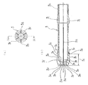
- FIG. 3 shows the state at the time of manufacture before the slit-shaped clearance gap opening process of the holding body used for the heat exchanger manufacturing apparatus of this invention, (a) is a front view, (b) is HH of (a).
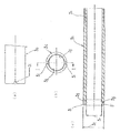
- FIG. 4 shows a gripping body guide cylinder used in a heat exchanger manufacturing apparatus provided with the gripping body of the present invention, wherein (a) is a partially enlarged view, (b) is a front view, and (c) is (b) II sectional view taken on the line II.
- FIG. 5 shows a use state of the gripping body used in the heat exchanger manufacturing apparatus of the present invention before the slit-shaped gap opening processing, (a) is a sectional view before gripping the tube, and (b) is after gripping the tube.
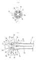
- FIG. 6A and 6B show a state after the slit-shaped gap opening processing of the gripping body used in the heat exchanger manufacturing apparatus of the present invention, FIG. .
- FIG. 5 shows a use state of the gripping body used in the heat exchanger manufacturing apparatus of the present invention before the slit-shaped gap opening processing
- FIG. 6A and 6B show a state after the slit-shaped gap opening processing of the gripping body used in the heat exchanger manufacturing apparatus
- FIG. 7 shows the use state of the gripper used in the heat exchanger manufacturing apparatus of the present invention after the slit-shaped gap opening processing
- (a) is a cross-sectional view when gripping the inclined pipe
- (b) is the pipe. Sectional drawing at the time of holding a pipe
- FIG. 8 is a cross-sectional view showing another embodiment of the gripping body used in the heat exchanger manufacturing apparatus of the present invention after the slit-shaped gap opening processing.
- FIG. 9 is a partial cross-sectional view showing another embodiment of the gripping body used in the heat exchanger manufacturing apparatus of the present invention after the slit-shaped gap opening processing.
- FIG. 10 shows an embodiment of a product including a heat exchanger manufactured by using a heat exchanger manufacturing apparatus including a gripping body of the present invention, and (a) is an air conditioner including a heat exchanger. (B) is an outdoor unit equipped with a heat exchanger used in an air conditioner.
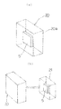
- FIG. 11 is an enlarged partial cross-sectional view of a main part of a clamping body used in a conventional heat exchanger manufacturing apparatus.
- 12A and 12B show a conventional heat exchanger manufacturing apparatus, in which FIG. 12A is an enlarged front view during tube expansion, FIG. 12B is a perspective view of a clamp, and FIG.
- the gripping body guide cylinder is used as the sliding means, and the heat exchanger manufacturing apparatus including the gripping body on which the guide cylinder is slidably fitted is used to reduce the size of the heat.
- the heat exchanger manufacturing apparatus including the gripping body on which the guide cylinder is slidably fitted is used to reduce the size of the heat.
- the mounting table 1c is reduced in size (thin tubes, etc.) by energy saving and cost reduction, and the hairpin tubes 7 are inserted into the radiating fins 6 in a plurality of rows such as a staggered shape, three rows, and four rows, for example.
- the heat exchanger 5 in which the interval between the tubes 7 and the interval between the adjacent hairpin tubes 7 is remarkably narrow (the hairpin tubes 7 inserted in a plurality of rows such as a staggered shape, three rows, four rows, etc. are not shown) After that, the pressure plate 11 positioned above is lowered, and the heat exchanger 5 is pressed and fixed to the mounting table 1c.
- a predetermined number of a pair of sandwiching bodies 4a provided facing the hairpin portions 7c of the hairpin tube 7 inserted through the heat radiating fins 6 of the heat exchanger 5 are moved to the sandwiching body provided with the sandwiching bodies 4a.
- the reciprocating cylinder 4f of the device 4 is actuated to advance the base 4d along the guide rail 12 (not shown), and the drive cylinder 4e is driven to form a generally tongue-like shape in plan view of each pair of sandwiching bodies 4a.
- the concave portions 4g hold the hairpin portions 7c of the hairpin tubes 7 protruding from the heat radiating fins 6 of the heat exchanger 5, respectively.
- the opposing planes of the pair of holding bodies 4a In order to more firmly prevent the shrinkage of the hairpin tube 7 during the tube expansion, the inner surface of the generally tongue-shaped concave portion 4g is inserted into the substantially U-shaped inner peripheral surface portion of the hairpin portion 7c. Prevents movement of the circumferential surface in the shrinking direction Viewed substantially tongue-shaped convex portion 4c which is provided to face.
- each expansion mandrel 2 is press-fitted at a predetermined depth (arrow A) from the tube opening 7b of each hairpin tube 7 to expand the expansion portion 7d having a predetermined length. Then, the peripheral surface portion is moved forward (arrow B) through the gripping body holding member 3l to the peripheral portion 7e of the tube expansion portion 7d from the tube mouth portion 7b side of the hairpin tube 7. 7e is externally fitted in an enclosed state by a plurality of tube abutting members 3f that can be expanded and contracted in the holding body 3.
- the holding body 3 having the plurality of pipe contact members 3f that can be expanded and contracted is manufactured by the following process. That is, as will be described later, as shown in FIG. 6 to FIG. 9, one end side of the gripping body (3) facing the tube opening 7b side of the hairpin tube 7 and fitted on the tube expansion mandrel (2) The inside of the gripping body (3) is moved from the other end side of the gripping body (3) having a predetermined overall length to the one end side so as to be positioned on the tube opening (7b) side of the pipe (7).
- the axial direction of the gripping body (3) in order to form an inner diameter smaller than the inner diameter of the gripped gripping body (3) in the vicinity of one end side inside the gripping body (3) by cutting with a depth dimension.
- a step of forming a bulging portion (3z) that bulges toward the end, and one end side of the gripping body (3) before forming the bulging portion (3z) or after forming the bulging portion (3z) Forming an inclined surface (3m), which is inclined in a direction expanding toward the tube opening (7b) side of the opposite pipe (7), on the inner peripheral surface of the tip (3o) by cutting or polishing; From the one end side of the gripping body (3), a plurality of pipe abutting members (3f) that are radially expandable and contractable in the direction intersecting the longitudinal direction of the pipe (7) are formed on the gripping body (3).
- the plurality of slit-like gaps By forming a plurality of slit-like gaps (3a) with a predetermined width dimension (3u) along the longitudinal direction of the gripping body (3) toward the other end side with a predetermined length dimension, the plurality of slit-like gaps ( A plurality of tubes provided with a protrusion (3e) protruding in the axial direction of the gripping body (3) by dividing the bulging part (3z) into the number of slit-shaped gaps (3a) via 3a)
- the body (3) is manufactured, and then a substantially conical jig (not shown) or a slit-like gap (3
- the inclined surface (3b) In order to unify the accuracy of the inclination degree (inclination angle) of each inclined surface (3b) by press-fitting a rod-shaped jig (not shown) provided with a plurality of sharp convex bodies to be inserted into the slits.
- the inclined surface (3b) has the gripping body before the slit-like gap (3a) having a predetermined width dimension (3u) is formed. Since it is formed by cutting or polishing the outer peripheral surface of (3), at the time of cutting or polishing, there is no slit-like gap (3a), that is, no bending, on the outer peripheral surface of the gripping body (3). There is an effect that the inclined surface (3b) with high accuracy can be formed.
- each of the slit-shaped gaps (3a) is inserted from a predetermined position through press-fitting of the substantially conical jig (not shown) or a rod-like jig (not shown) having a plurality of sharp convex bodies.
- each pipe contact member (3f) is expanded.
- the inclination of the inclined surface (3b) provided on the outer surface and inclined in the direction of expanding toward the tube opening (7b) side of the opposing tube (7) is the inclined surface (3b) when the slit-shaped gap (3a) is formed.
- a gripping body (3) having a plurality of tube abutting members (3f) provided with projections (3e) projecting in the axial direction of the gripping body (3) from the step of forming larger than the inclination degree of ) Can be manufactured.
- the step of forming the inclined surface (3m) by cutting includes a predetermined width dimension (3u) along the longitudinal direction of the gripping body (3) from one end side to the other end side of the gripping body (3). ) May be formed at any time before the step of forming a plurality of slit-shaped gaps (3a) with a predetermined length dimension, and the cutting process of the inclined surface (3m) is performed at the other end of the gripping body (3).
- the gripping body (3) cut in the vicinity of one end side inside the gripping body (3) by cutting the inside of the gripping body (3) with a predetermined depth from the side to the one end side. There is no particular problem whether it is after or before the step of forming the bulging portion (3z) bulging in the axial direction of the gripping body (3) so as to form an inner diameter smaller than the inner diameter of Needless to say.
- the gripping body guide cylinder 3c is provided on the outer surface of each tube abutting member 3f of the gripping body 3, and slides on the inclined surface 3b inclined in the direction of expanding toward the tube opening 7b side of the opposing tube 7.
- the diameter of each of the tube abutting members 3f is reduced in the axial direction of the mandrel 2 for expanding the tube, that is, anti-radially, through each of the distance spaces of the slit-shaped gap 3a having a predetermined width 3u.
- each tube contact member 3f firmly holds and holds the peripheral surface portion 7e of the expanded portion 7d of the hairpin tube 7.
- the tube contact member 3f includes the gripper guide tube 3c and the tube contact member 3f.
- each of the slit-shaped gaps (3 a) A slit shape having a constant width dimension without expanding the predetermined width dimension (3u) to an enlarged width dimension (3x) gradually from the pipe (7) toward the tube opening (7b).
- the tube contact member 3f particularly contacts the expanded portion 7d of the hairpin tube 7 as shown in FIG. 2 (d).
- a bulging portion 7g can be formed in the tube inner peripheral portion 7f of the hairpin tube 7 in the axial direction of the mandrel 2.
- a protrusion 3e [the protrusion 3e described in FIG. 2 (d) has the same function as the protrusion 3e shown in FIGS. ], It is possible to more reliably set the reference position of the tube port portion 7b at the time of tube expansion by gripping and holding the peripheral surface portion 7e of the tube expansion portion 7d more firmly.
- both the hairpin portion 7c and the tube opening portion 7b are held, thereby minimizing the contraction of the entire length of the hairpin tube 7.
- the heat exchanger manufacturing apparatus provided with the gripping body 3 and the guide tube 3c disclosed in FIGS. 3 to 5 as described above, the intervals between the hairpin tubes 7 and the hairpin tubes 7 located next to each other.
- the heat exchanger manufacturing apparatus 1 is provided with an expanded tube that can be press-fitted from the tube port portion 7b of the tube 7 inserted into the heat radiating fins 6 of the heat exchanger 5.
- a plurality of tube contact members 3f that can be reciprocally fitted to the mandrel 2 and that can be radially expanded and contracted in a direction intersecting the longitudinal direction of the tube 7, and the outer surface of the tube contact member 3f Is formed with an inclined surface 3b inclined in a direction extending toward the tube opening 7b side of the opposing tube 7, and reciprocally slides along the inclined surface 3b of the tube contact member 3f in the longitudinal direction of the tube.
- a guide tube 3c that radially expands and contracts each of the tube contact members 3f.
- a heat exchanger insertion tube gripping body 3 is provided, and an inner surface of the tube contact member 3f on the tube opening 7b side is provided with a protrusion 3e protruding in the axial direction of the tube 7, and When the tube contact member 3f is externally fitted to the projection 3e from the side of the tube port 7b of the tube 7, the tube port 7b is deformed by the collision between the projection 3e and the tube port 7b of the tube 7.
- an inclined surface 3m inclined in a direction extending from the top 3p of the protrusion 3e toward the tube opening 7b of the tube 7 facing the tip 3o of the tube contact member 3f is provided, and the guide tube On the inner peripheral surface of the tip of 3c, an inclined surface that is inclined in a direction that expands toward the tube opening 7b side of the opposite tube 7 so as to reduce sliding wear with the inclined surface 3b of the outer surface of the tube contact member 3f. 3g is provided, and the inclined surface 3b provided on the outer surface of the tube abutting member 3f of the gripping body 3 is provided with the tube abutting portion.
- the holding body 3 is advanced to the peripheral surface portion 7 e of the expanded portion 7 d of the pipe 7 having a predetermined pipe diameter 7 h as a reference via a holding body holding member 3 l (not shown). Then, the gripping body guide tube 3c is moved forward (arrow J) to the tube port 7b side of the tube 7 through the guide tube holding member 3d, so that the tube contact of the gripping body 3 is achieved.
- Each of the members 3f reduces the diameter of the expanded portion 7d of the tube 7 having a predetermined tube diameter 7h (arrow K) via the spatial distance of the slit-shaped gap 3a having a predetermined width 3u provided between the tube contact members 3f. ), And the protrusion 3e provided on the tube contact member 3f is a peripheral surface of the expanded portion 7d. 7e is pressed to form a bulging portion 7g (not shown) in the axial direction of the tube 7 on the peripheral surface portion 7e, and more firmly gripped and held by the tube abutting member 3f at the time of tube expansion.
- the outer diameter 3q of the gripping body guide tube 3c fitted on the gripping body 3 having the tube contact member 3f is reduced in diameter through the slit-shaped gap 3a having a predetermined width 3u.
- the distance between the tops of the inclined surfaces 3b of the opposed pipe contact members 3f is 3n. It is possible to set the tube expansion portion 3s having the outer diameter 3n when the diameter of the member 3f is reduced to a position 3t separated from the tip 3o of the tube contact member 3f in the direction opposite to the tube opening 7b.
- the inner diameter dimension 3r of the gripping body guide cylinder 3c can be reduced by the separated distance, and as a result, the outer diameter dimension 3q of the gripping body guide cylinder 3c can be reduced naturally.
- the holding body guide cylinder 3c having a smaller outer diameter 3p makes contact between the adjacent holding body guide cylinders 3c.
- Each of the straight pipes and hairpin pipes 7 that are reduced in size (thin tubes, etc.) by energy saving and cost reduction and inserted into the heat radiating fins of the heat exchanger and the heat radiating fins 6 are inserted in a staggered manner.
- the heat exchanger 5 in which not only the distance between the straight pipes and the hairpin pipes 7 but also the straight pipes and the hairpin pipes are inserted into the radiating fins 6 in a plurality of rows such as three rows and four rows, so that the interval between the tubes is remarkably reduced. There is an advantage that can be manufactured satisfactorily.
- an inclined surface 3b provided on the outer surface of the tube abutting member 3f to avoid reaching the tip 3o of the tube abutting member 3f of the holding body 3 as described above is a tube.
- the tube contact member 3f is provided on the rear side opposite to the tip 3o from the formation position of the protrusion 3e provided on the inner surface of the tube opening 7b side of the contact member 3f, the diameter of the tube contact member 3f is reduced. It is possible to set the pipe expansion portion 3s having the outer diameter dimension 3n to a position 3t that is farthest away from the tip 3o of the pipe contact member 3f in the direction opposite to the pipe opening 7b, and thus the separated distance.
- the outer diameter dimension 3q of the gripping body guide tube 3c can be set to the minimum.
- the interval of the tube 7 and the interval or insertion of each hairpin tube 7 located next to the tube 7 Even when the distance between the straight pipes becomes extremely narrow, the pipe abutment of the gripping body 3 having the gripping body guide cylinder 3c from the tube port portion 7b of each straight pipe or each hairpin pipe 7
- the gripping body guide cylinder 3c having the smallest outer diameter 3p can avoid contact between the gripping body guide cylinders 3c located next to each other.
- the straight tubes and hairpin tubes 7 that are ultra-miniaturized (extra-thin tubes, etc.) and that are inserted through the heat dissipating fins of the heat exchanger and the spacing between the hairpin tubes 7 and the heat dissipating fins 6 are staggered.
- the heat exchanger 5 in which the straight pipes and the hairpin pipes are inserted into the heat radiating fins 6 in a plurality of rows such as three rows and four rows as well as the intervals between the tubes is manufactured optimally. There is an advantage that you can.
- the holding body 3 having the above-described configuration is provided with a tool locking portion 3j used for attaching and detaching the holding body 3 to and from the holding body holding member 3l
- the tool locking portion 3j In addition, for example, by simply locking and rotating a tool such as a screwdriver, not only replacing the gripping body 3 due to wear or the like, but also the interval between the hairpin tubes 7 and the interval between each hairpin tube 7 or the insertion.
- a tool such as a screwdriver
- the tool locking portion 3i includes, for example, By simply locking and rotating a tool such as a screwdriver, not only the replacement of the guide tube 3c due to wear or the like, but also the interval between the hairpin tubes 7 and the distance between each adjacent hairpin tube 7 or each inserted straight.
- a slit-like gap having a predetermined width dimension is formed from a predetermined position toward the tube mouth portion of the pipe so as to form a tube contact member of the gripping body.
- the gripping body 3 of the heat exchanger insertion tube used in the heat exchanger manufacturing apparatus for realizing the heat exchanger manufacturing method is the tube 7 inserted into the radiating fins 6 of the heat exchanger 5.
- An inclined surface 3b is formed on the outer surface of the tube abutting member 3f so as to be inclined toward the tube port 7b side of the opposite tube 7, and the inclined surface 3b of the tube abutting member 3f is connected to the tube.
- Each of the tube contact members 3f is radially expanded / reduced through sliding means that reciprocally slides in the longitudinal direction of the tube, and the plurality of radially expandable / contractable tube contact members 3f are tube expansion mandrels.
- a plurality of gripping bodies 3 in the longitudinal direction along the reciprocating direction of 2 In the configuration formed through the slit-shaped gap 3a having the predetermined width dimension 3u, the slit-shaped gap 3a gradually expands the predetermined width dimension 3u from the predetermined position toward the tube opening 7b of the pipe 7.
- a pipe 7 having a predetermined pipe diameter 7h serving as a reference has an axial direction of the expanded portion 7d of the pipe 7 along the longitudinal direction of the mandrel. Even when it is slightly inclined so as to deviate from the axial direction of the gripping body 3 along the longitudinal direction, the maximum opening diameter 3y and the amount of expansion / contraction range are greatly increased through each tube contact member 3f. Thus, there is an advantage that it is possible to surely prevent at least one of the tip end of the tube abutting member 3f and the tube opening 7b of the tube 7 from contacting or abutting to be deformed or damaged.
- the slit-shaped gap 3a of the gripping body 3 is an enlarged width dimension in which the predetermined width dimension 3u is gradually enlarged from a predetermined position toward the tube opening 7b of the pipe 7.
- the outer diameter 7i of the expanded portion 7d on the tube opening 7b side of the tube 7 is the inner diameter of the gripping body 3 itself or the inner diameter of the tube contact member 3f (the inner diameter between the protrusions).
- the plurality of tube contact members 3f that are radially expandable / contractible of the gripping body 3 are arranged so that the slit-shaped gap 3a extends from a predetermined position toward the tube opening 7b of the tube 7.
- each tube abutting member 3f is changed from the maximum opening diameter 3y to the minimum opening diameter in proportion to the sliding distance of the guide tube 3c (the outer diameter of the tube expansion portion of the tube).
- the anti-radial shrinkage amount is different, there is an advantage that the expansion / contraction range amount can be adjusted as easily and reliably as possible until a so-called gripping operation).
- a protrusion 3e that protrudes in the axial direction of the tube 7 is provided on the inner surface of the tube contact member 3f of the gripping body 3 on the tube mouth portion 7b side.
- the tube contact member 3f is externally fitted to the protrusion 3e from the tube opening 7b side of the tube 7, the tube opening 7b due to the collision between the protrusion 3e and the tube opening 7b of the tube 7 is provided.
- an inclined surface 3m that is inclined in a direction that expands toward the tube opening 7b side of the tube 7 that faces the tip 3o of the tube contact member 3f from the top 3p of the protrusion 3e is provided.
- the protrusion 3e is smoothly connected to the tube 7 via the inclined surface 3m or the curved surface.
- the tube abutting member 3f having the protrusion 3e and the tube 7 can be slid along the tube opening 7b. There is an advantage that it is possible to reliably prevent the deformation and damage of the mouth portion 7b.
- the guide cylinder 3c is opposed to the inner peripheral surface at the tip thereof so as to reduce sliding wear with the inclined surface 3b of the outer surface of the tube contact member 3f.
- An inclined surface 3g or a curved surface that is inclined in a direction that expands toward the tube opening 7b side of the tube 7 that is to be formed, and an inclined surface 3b that is provided on the outer surface of the tube contact member 3f of the gripping body 3 is provided.
- the distance between the hairpin tubes 7 and the distance between the adjacent hairpin tubes 7 is significantly narrower than the conventional intervals.
- the tube contact member 3f When the distance between the tops of the inclined surfaces 3b of the tube contact member 3f is determined as a reference diameter (the inner diameter 3r as viewed from the gripping body guide tube 3c) as the outer diameter 3n, the tube contact member 3f It is possible to set the tube expansion portion 3s having the outer diameter 3n when the diameter is reduced to a position 3t separated from the tip 3o of the tube contact member 3f in the direction opposite to the tube opening 7b. It is possible to reduce the inner diameter 3r of the gripper guide cylinder 3c by the distance, and as a result, the outer diameter 3q of the gripper guide cylinder 3c can also be reduced naturally.
- the holding body guide cylinder 3c is provided from the tube port portion 7b of each straight tube or hairpin tube 7.
- the gripping body guide cylinder 3c having a small outer diameter 3q avoids the abutment of the adjacent gripping body guide cylinders 3c.
- a sliding means that reciprocally slides in the longitudinal direction of the inclined surface 3b of the tube contact member 3f of the gripping body 3 uses a guide cylinder 3c.
- the outer diameter 3w of the guide tube 3c and the maximum outer diameter 3v of the gripping body 3 comprising the pipe contact member 3f facing each other so as to have the inclined surface 3b are the maximum outer diameter of the gripping body 3.
- the tube abutting member 3f can be accommodated within the outer diameter 3w of the guide tube 3c in a state where it is enlarged from the slit-shaped gap 3a having a predetermined width 3u, and accordingly, the tube spacing of the hairpin tube 7 and each adjacent The interval between the hairpin tubes 7 or the interval between the straight tubes inserted is the conventional Even when the distance between the guide cylinders 3c is increased corresponding to the case where the distance between the guide cylinders 3c becomes narrower than the distance, the pipe abutting members 3f of the gripping bodies 3 housed in the respective adjacent guide cylinders 3c are interposed. Thus, even when the tube 7 is operated to grip the expanded portion 7d on the tube opening 7b side, there is an advantage that the contact or contact of the adjacent tube contact member 3f can be surely prevented.
- the holding body 3 that expands and contracts radially when the holding body 3 is held by the holding body holding member 3l.
- a restricting means such as a notch N, a recess (not shown), or a protrusion (not shown) for restricting the expansion / contraction position of the tube contact member 3f (rotation restriction with respect to the holding body holding member 3l) is provided.
- the holding state of the gripping body holding member 3l or other parts corresponding to the control means of the gripping body 3 comes into contact with or comes into contact with the control means to hold the control state.
- a mandrel for tube expansion is press-fitted at a predetermined depth from a tube port portion of a tube inserted into the heat radiating fin of the heat exchanger, and a tube expansion portion having a predetermined length is formed.
- a first step to be formed, and a plurality of slit-shaped gaps having a predetermined width dimension provided in the longitudinal direction along the reciprocating direction of the tube expansion mandrel, and the slit-like gaps are A gripping body of a heat exchanger insertion tube having a plurality of pipe abutting members that are radially expandable / contractable so as to have an enlarged width dimension that gradually expands the predetermined width dimension toward the pipe opening direction.
- a tube contact member formed on the outer surface of the tube contact member and having an inclined surface inclined in a direction extending toward the tube opening side of the opposite tube. Press while sliding the inclined surface of the tube toward the tube mouth side
- Each of the tube abutting members is reduced in diameter in the axial direction of the mandrel for tube expansion so as to gradually reduce the expanded width dimension obtained by gradually increasing the predetermined width dimension of the slit-shaped gap from the predetermined position via the sliding means.
- the heat exchanger is manufactured by the heat exchanger manufacturing method comprising the fourth step of integrating the radiating fin and the tube by further press-fitting the tube expansion mandrel into the tube while being held
- the slit-shaped gap 3a is formed so as to have an enlarged width dimension 3x obtained by gradually expanding the predetermined width dimension 3u from the predetermined position toward the tube opening 7b of the pipe 7
- the tube contact member 3f is externally fitted from the side of the portion 7b, the tube mouth portion 7b of the tube 7
- a plurality of predetermined opening diameters 3y (arrows M) and expansion / contraction range amounts (space distances) of the pipe contact members 3f facing each other are provided in the longitudinal direction of the gripper 3 so as to form the pipe contact members 3f. It is possible to
- the pipe 7 having a predetermined pipe diameter 7h serving as a reference has the axial direction of the expanded portion 7d of the pipe 7 along the longitudinal direction of the mandrel.
- Each tube contact member in which the maximum opening diameter 3y and the amount of expansion / contraction range are greatly expanded even when it is slightly inclined so as to deviate from the axial direction of the gripping body 3 along the longitudinal direction of the mandrel 2 There is an advantage that it is possible to reliably prevent at least one of the tip end of the tube contact member 3f and the tube opening 7b of the tube 7 from contacting or abutting via 3f and deforming or breaking.
- the slit-shaped gap 3a of the holding body 3 extends from the predetermined position toward the tube port 7b of the tube 7.
- the predetermined width dimension 3u is formed so as to have an expanded width dimension 3x that is gradually increased toward the end
- the outer diameter 7i of the expanded portion 7d on the side of the mouth portion 7b of the tube 7 is equal to that of the gripping body 3 itself. Even when the inner diameter and the inner diameter between the tube contact members 3f (the inner diameter between the protrusions when the protrusions are provided) are approximately the same diameter 7i (larger than a certain predetermined pipe diameter 7h).
- the tip of the tube contact member 3f and the tube opening 7b of the tube 7 come into contact or contact with each other via the tube contact member 3f with the maximum opening diameter 3y and the expansion / contraction range expanded, and at least one of them is deformed. There is an advantage that damage can be surely prevented.
- the heat exchanger 5 manufactured by the heat exchanger manufacturing method using the gripping body of the heat exchanger insertion tube as shown in FIG.
- the air conditioner 20 housed in the casing 20a or the manufactured heat exchanger 5 is sold in the outdoor unit 21 used in the air conditioner 20, as shown in FIG.
- the distribution cost and the product cost can be significantly reduced through the heat exchanger that is reduced in size by reducing the pipe diameter and / or bringing the interval between adjacent pipes closer.
- the heat exchanger 5 manufactured by the manufacturing method of the present invention as described above is used for the air conditioner 20 or the outdoor unit 21 used in the air conditioner 20, such an air conditioner is a so-called air handling unit or fan. It can be a central air conditioner called a coil unit, or an individual air conditioner called a packaged air conditioner or room air conditioner. In short, if it is an air conditioner using a heat exchanger, its specific structure Needless to say, the shape, type, size, system configuration, etc. are not limited at all. Moreover, the heat exchanger manufactured by the manufacturing method of this invention may be used for the product of various fields, and a use field, a sales field, etc. are not limited at all.
- a large number of hairpin tubes 7 do not necessarily have to be inserted into the heat radiating fins 6 of the heat exchanger 5. ) May be inserted, and the material, shape, type, number, insertion pattern, etc. of the tube used are not limited at all.
- the heat exchanger manufacturing apparatus including the gripping body 3 having the tube contact member 3f and the gripping body guide cylinder 3c slidably fitted thereto is a so-called horizontal type.
- a tube expansion device it is not necessary to be a horizontal tube expansion device, it may be a vertical tube expansion device, and not only the specific structure, type and characteristics of the heat exchanger manufacturing apparatus, but also the number of tube contact members Needless to say, the (number of sheets), the number of the gripping bodies and the sandwiching bodies, the arrangement, the arrangement location, and the like are not limited.
- the method for manufacturing a gripping body according to the present invention is a method of manufacturing a gripping body 3 that can be fitted on the tube expansion mandrel 2 and has a predetermined overall length so that one end side is positioned on the tube opening 7b side of the pipe 7.
- the inner diameter is smaller than the inner diameter of the gripped gripping body 3 in the vicinity of one end side inside the gripping body 3.
- the bulging site 3z is formed via the plurality of slits 3a.
- the axis of the gripper 3 from the step of forming the inclination of the inclined surface 3b inclined in the direction of expanding toward the tube opening 7b of the tube 7 to be larger than the inclination of the inclined surface 3b when the slit-like gap 3a is formed.
- the gripping body 3 having a plurality of pipe contact members 3f provided with the protrusions 3e protruding in the core direction is manufactured, according to the gripping body 3 manufactured by such a manufacturing method, the pipe 7 When fitting the tube contact member 3f from the tube opening 7b side A plurality of maximum opening diameters 3y and expansion / contraction range amounts of the respective tube contact members 3f facing the tube opening 7b of the tube 7 are provided in the longitudinal direction of the gripping body 3 so as to form the respective tube contact members 3f.
- the predetermined width dimension 3u is gradually expanded to have an expanded width dimension 3x so that the predetermined width dimension 3u can be expanded. Accordingly, the outer diameter 7i of the expanded portion 7d on the tube opening 7b side of the tube 7 can be increased.
- the axial direction of the expanded portion 7d along the longitudinal direction of the mandrel is the longitudinal direction of the mandrel.
- the tip end of the tube contact member 3f and the tube opening 7b of the tube 7 is in contact with or in contact with each other via the tube contact member 3f having the maximum opening diameter 3y and the expansion / contraction range amount increased.
- the bulging portion 3z is divided into the number of slit-like gaps 3a via a plurality of slit-like gaps 3a. Therefore, the projection dimension (height dimension) of the projection 3e itself, the total length of the projection 3e itself (the length of the projection 3e along the axial direction of the gripping body 3), etc.
- the protrusion 3e is provided with a tube contact member 3f from the tube opening 7b side of the tube 7. The pipe opening due to the collision between the protrusion 3e and the pipe opening 7b of the pipe 7 when fitted externally.
- an inclined surface 3m is provided that is inclined in a direction that expands from the top 3p of the protrusion 3e toward the tube opening 7b of the tube 7 facing the tip 3o of the tube contact member 3f. Therefore, even when the tube opening 7b of the tube 7 and the projection 3e of the tube abutting member 3f are in contact with or in contact with each other, the projection 3e is smoothly connected to the tube via the inclined surface 3m or the curved surface. 7 can be slid along the tube port portion 7b, so that deformation and breakage of the tube contact member 3f having the protrusion 3e and the tube port portion 7b of the tube 7 can be reliably prevented. It is in providing the manufacturing method of the holding body.
- the present invention expands the pipe using a pipe gripping body so as to keep the entire length of the pipe inserted through each through hole of the heat dissipating fins of the plurality of superposed heat exchangers substantially the same as before the pipe expansion. It can be formed integrally with the radiating fins, and even if the tubes inserted through the radiating fins are close to each other to form three or four rows, the tubes are expanded. Even if the tube diameter is slightly different depending on the type of heat exchanger specifications, the distance between each straight tube and each hairpin tube inserted through the heat-dissipating fins is significantly narrower than before.
- the outer diameter of the tube is substantially the same as the inner diameter of the gripping body itself or the inner diameter between the abutting members (the inner diameter between the projecting bodies when the projecting body is provided inside the abutting member).
- the diameter of the expanded section along the longitudinal direction of the expanded section mandrel In order to solve all of the above problems, even if the direction is slightly inclined so as to deviate from the axial center direction of the gripping body along the longitudinal direction of the mandrel, The tube mouth portion of the tube located securely and firmly inside the heat exchanger while reliably preventing deformation or breakage due to contact or contact with the tip of the tube abutting member of the tube gripping body.
- the present invention relates to a method and an air conditioner and / or an outdoor unit having the manufactured heat
Landscapes
- Engineering & Computer Science (AREA)
- Mechanical Engineering (AREA)
- Physics & Mathematics (AREA)
- Geometry (AREA)
- Thermal Sciences (AREA)
- General Engineering & Computer Science (AREA)
- Heat-Exchange Devices With Radiators And Conduit Assemblies (AREA)
- Details Of Heat-Exchange And Heat-Transfer (AREA)
Abstract
Description
即ち、上記構成からなる熱交換器製造装置1によれば、対向する管7の管口部7b側に向かって拡がる方向に傾斜した傾斜面3bが形成されると共に、ヘアピン管7の長手方向と交差する方向に放射状で拡縮自在(矢印E)な複数の管当接部材3fを有する掴持体3が管7の管口部7bから往復動自在に外嵌可能で、且つ前記傾斜面3bは管当接部材3fの先端3oにまで届くべく形成され、しかも該掴持体3は上記管当接部材3fと反する他端側に設けられた雄螺子部3kを、ヘアピン管7の長手方向にシリンダー(図示せず)等の往復動作手段を介して所定のピッチで往復動自在(矢印F)な掴持体保持部材3lに螺着されて保持されると共に、該掴持体3にはシリンダー(図示せず)等の往復動作手段を介して往復動自在(矢印G)なガイド筒保持部材3dに、他端部に設けられた雄螺子部3hを介して螺着保持された掴持体ガイド筒3cが摺動自在に外嵌されてなることから、該ガイド筒3cを管当接部材3fの傾斜面3bに沿って管7の管口部7b側に向かって摺動させることで管当接部材3fの夫々を反放射状で縮径させつつ、管当接部材3fの管口部7b側の内面に設けられた突起体3eによりヘアピン管7の拡管部7dの周面部7eを押圧して該周面部7eに管7の軸芯方向に膨出部7gを形成させてより強固に掴持して保持することで拡管時に於ける管口部7bの基準位置をより確実に設定することが可能となりより高い精度を有した拡管作業を介して寸法精度の極めて高いより高品質の熱交換器を生産することが出来るものであるが、如何せん、上記構成からなる掴持体3の管当接部材3fの傾斜面3bは管当接部材3fの先端3oにまで届くべく形成されてなることから、ガイド筒3cの先端が管当接部材3fの先端3oに届く位置まで該ガイド筒3cを管当接部材3fの傾斜面3bに摺動させながら前進させる必要がある。
即ち、請求項1記載の発明は、熱交換器製造装置(1)に用いられ、且つ熱交換器(5)の放熱フィン(6)に挿通された管(7)の管口部(7b)から圧入可能な拡管用マンドレル(2)に往復動自在に外嵌可能で、しかも前記管(7)の長手方向と交差する方向で放射状に拡縮自在な複数の管当接部材(3f)を有し、且つ該管当接部材(3f)の外面には、対向する管(7)の管口部(7b)側に向かって拡がる方向に傾斜した傾斜面(3b)が形成され、しかも該管当接部材(3f)の傾斜面(3b)を管の長手方向に往復自在に摺動する摺動手段を介して管当接部材(3f)の夫々を放射状に拡縮させる熱交換器挿通管の掴持体(3)の製造方法であって、所定の全長を有した掴持体(3)の他端側より管(7)の管口部(7b)側方向となる一端側へと該掴持体(3)の内部を所定の深さ寸法で切削することで掴持体(3)の内部の一端側近傍に、切削された掴持体(3)の内径より小さい内径を形成すべく掴持体(3)の軸芯方向へと膨出する膨出部位(3z)を形成する工程と、該膨出部位(3z)が形成された後に、掴持体(3)に管(7)の長手方向と交差する方向で放射状に拡縮自在な複数の管当接部材(3f)を形成すべく、該掴持体(3)の一端側から他端側へと掴持体(3)の長手方向に沿って所定幅寸法(3u)のスリット状隙間(3a)を所定の長さ寸法で複数形成することにより、該複数のスリット状隙間(3a)を介して前記膨出部位(3z)をスリット状隙間(3a)の数に分割して掴持体(3)の軸芯方向へと突出した突起体(3e)を備えた複数の管当接部材(3f)を形成する工程と、該スリット状隙間(3a)の夫々を所定箇所から前記管(7)の管口部(7b)方向に向かって前記所定幅寸法(3u)を徐々に拡大した拡大幅寸法(3x)を有すべく拡げることにより、各管当接部材(3f)の外面に設けられ、しかも対向する管(7)の管口部(7b)側に向かって拡がる方向に傾斜した傾斜面(3b)の傾斜度合いをスリット状隙間(3a)の形成時の傾斜面(3b)の傾斜度合より大きく形成する工程とから掴持体(3)の軸芯方向へと突出した突起体(3e)を備えた複数の管当接部材(3f)を有した掴持体(3)を製造することにある。
かかる一実施形態では、摺動手段に掴持体ガイド筒を用いると共に、該ガイド筒を摺動自在に外嵌した掴持体を備えた熱交換器製造装置を用いて、小型化された熱交換器や管径の異なる各種の挿通管のみならず、各管の間隔が著しく狭くなった熱交換器を製造する場合等について説明するが、該熱交換器製造装置の各部構成について、従来の構成と同じ箇所の説明は省略するものとする。尚、掴持体の管当接部材を形成すべく所定幅寸法のスリット状隙間が所定箇所から管の管口部方向に向かって前記所定幅寸法を徐々に拡大した拡大幅寸法を有した管当接部材を備えた構成の掴持体の一実施形態に関しては、以下、先に説明する掴持体の管当接部材自体の構成の一実施形態と作用効果の違いから別けて後段にて説明する。
1a 製造装置本体
2 拡管用マンドレル
3 掴持体
3a スリット状隙間
3b 管当接部材の傾斜面
3c 掴持体ガイド筒
3d ガイド筒保持部材
3e 突起体
3f 管当接部材
3g 傾斜面
3h 掴持体ガイド筒の雄螺子部
3i 掴持体ガイド筒の道具係止部
3j 掴持体の道具係止部
3k 掴持体の雌螺子部
3l 掴持体保持部材
3o 掴持体の先端
3p 突起体の頂部
4 挟持体移送装置
5 熱交換器
6 放熱フィン
7 ヘアピン管(又は直管)
Claims (7)
- 熱交換器製造装置(1)に用いられ、且つ熱交換器(5)の放熱フィン(6)に挿通された管(7)の管口部(7b)から圧入可能な拡管用マンドレル(2)に往復動自在に外嵌可能で、しかも前記管(7)の長手方向と交差する方向で放射状に拡縮自在な複数の管当接部材(3f)を有し、且つ該管当接部材(3f)の外面には、対向する管(7)の管口部(7b)側に向かって拡がる方向に傾斜した傾斜面(3b)が形成され、しかも該管当接部材(3f)の傾斜面(3b)を管の長手方向に往復自在に摺動する摺動手段を介して管当接部材(3f)の夫々を放射状に拡縮させる熱交換器挿通管の掴持体(3)の製造方法であって、所定の全長を有した掴持体(3)の他端側より管(7)の管口部(7b)側方向となる一端側へと該掴持体(3)の内部を所定の深さ寸法で切削することで掴持体(3)の内部の一端側近傍に、切削された掴持体(3)の内径より小さい内径を形成すべく掴持体(3)の軸芯方向へと膨出する膨出部位(3z)を形成する工程と、該膨出部位(3z)が形成された後に、掴持体(3)に管(7)の長手方向と交差する方向で放射状に拡縮自在な複数の管当接部材(3f)を形成すべく、該掴持体(3)の一端側から他端側へと掴持体(3)の長手方向に沿って所定幅寸法(3u)のスリット状隙間(3a)を所定の長さ寸法で複数形成することにより、該複数のスリット状隙間(3a)を介して前記膨出部位(3z)をスリット状隙間(3a)の数に分割して掴持体(3)の軸芯方向へと突出した突起体(3e)を備えた複数の管当接部材(3f)を形成する工程と、該スリット状隙間(3a)の夫々を所定箇所から前記管(7)の管口部(7b)方向に向かって前記所定幅寸法(3u)を徐々に拡大した拡大幅寸法(3x)を有すべく拡げることにより、各管当接部材(3f)の外面に設けられ、しかも対向する管(7)の管口部(7b)側に向かって拡がる方向に傾斜した傾斜面(3b)の傾斜度合いをスリット状隙間(3a)の形成時の傾斜面(3b)の傾斜度合より大きく形成する工程とから掴持体(3)の軸芯方向へと突出した突起体(3e)を備えた複数の管当接部材(3f)を有した掴持体(3)を製造することを特徴とする熱交換器挿通管の掴持体の製造方法。
- 熱交換器製造装置(1)に用いられ、且つ熱交換器(5)の放熱フィン(6)に挿通された管(7)の管口部(7b)から圧入可能な拡管用マンドレル(2)に往復動自在に外嵌可能で、しかも前記管(7)の長手方向と交差する方向で放射状に拡縮自在な複数の管当接部材(3f)を有し、且つ該管当接部材(3f)の外面には、対向する管(7)の管口部(7b)側に向かって拡がる方向に傾斜した傾斜面(3b)が形成され、しかも該管当接部材(3f)の傾斜面(3b)を管の長手方向に往復自在に摺動する摺動手段を介して管当接部材(3f)の夫々を放射状に拡縮させる熱交換器挿通管の掴持体(3)の製造方法であって、掴持体(3)の他端側より管(7)の管口部(7b)側方向となる一端側へと該掴持体(3)の内部を所定の深さ寸法で切削することで掴持体(3)の内部の一端側近傍に、切削された掴持体(3)の内径より小さい内径を形成すべく掴持体(3)の軸芯方向へと膨出する膨出部位(3z)を形成する工程と、該膨出部位(3z)を形成する前又は膨出部位(3z)を形成した後に、該掴持体(3)の一端側の先端(3o)内周面に、対向する管(7)の管口部(7b)側に向かって拡がる方向に傾斜した傾斜面(3m)を切削又は研磨により形成する工程と、掴持体(3)に管(7)の長手方向と交差する方向で放射状に拡縮自在な複数の管当接部材(3f)を形成すべく、該掴持体(3)の一端側から他端側へと掴持体(3)の長手方向に沿って所定幅寸法(3u)のスリット状隙間(3a)を所定の長さ寸法で複数形成することにより、該複数のスリット状隙間(3a)を介して前記膨出部位(3z)をスリット状隙間(3a)の数に分割して掴持体(3)の軸芯方向へと突出した突起体(3e)を備えた複数の管当接部材(3f)を形成する工程と、該スリット状隙間(3a)の夫々を所定箇所から前記管(7)の管口部(7b)方向に向かって前記所定幅寸法(3u)を徐々に拡大した拡大幅寸法(3x)を有すべく拡げることにより、各管当接部材(3f)の外面に設けられ、しかも対向する管(7)の管口部(7b)側に向かって拡がる方向に傾斜した傾斜面(3b)の傾斜度合いをスリット状隙間(3a)の形成時の傾斜面(3b)の傾斜度合より大きく形成する工程とから掴持体(3)の軸芯方向へと突出した突起体(3e)を備えた複数の管当接部材(3f)を有した掴持体(3)を製造することを特徴とする熱交換器挿通管の掴持体の製造方法。
- 前記対向する管(7)の管口部(7b)側に向かって拡がる方向に傾斜した傾斜面(3b)が、所定幅寸法(3u)のスリット状隙間(3a)の形成前に、前記掴持体(3)の外周面を切削又は研磨することにより形成されることを特徴とする請求項1又は2記載の熱交換器挿通管の掴持体の製造方法。
- 前記該スリット状隙間(3a)の夫々を所定箇所から前記管(7)の管口部(7b)方向に向かって前記所定幅寸法(3u)を徐々に拡大した拡大幅寸法(3x)を有すべく拡げることで、各管当接部材(3f)の外面に設けられ、しかも対向する管(7)の管口部(7b)側に向かって拡がる方向に傾斜した傾斜面(3b)の傾斜度合いをスリット状隙間(3a)の形成時の傾斜面(3b)の傾斜度合より大きく形成する工程が、該掴持体(3)の一端側より他端側方向へと圧入される略円錐状治具又は各所定幅寸法(3u)のスリット状隙間(3a)に挿入されるべく複数の先鋭凸状体を備えた棒状治具で行われることを特徴とする請求項1乃至3の何れかに記載の熱交換器挿通管の掴持体の製造方法。
- 前記請求項1乃至4の何れかに記載の製造方法により製造された熱交換器挿通管の掴持体を用いた熱交換器の製造方法であって、熱交換器の放熱フィンに挿通されたヘアピン管のヘアピン部をクランプ体で挟持して管口側方向への移動を規制するか、若しくは熱交換器の放熱フィンに挿通されたヘアピン管のヘアピン部をヘアピン管の長手方向と交差する方向で出退自在な係止体で管口側方向への移動を規制した後、該ヘアピン管の管口部から拡管用マンドレルを所定の深さ寸法で圧入して所定の拡管部を形成する第一工程と、拡管用マンドレルの往復動方向に沿った長手方向に複数設けられた所定幅寸法のスリット状隙間を介して形成され、しかも該スリット状隙間が所定箇所から前記管の管口部方向に向かって前記所定幅寸法を徐々に拡大した拡大幅寸法を有すべく放射状に拡縮自在な複数の管当接部材が設けられた熱交換器挿通管の掴持体を前記拡管部に包囲状態で外嵌する第二工程と、前記管当接部材の外面に設けられ、且つ対向する管の管口部側に向かって拡がる方向に傾斜した傾斜面が形成された管当接部材の傾斜面を管の管口部側に向かって摺動しつつ押圧する摺動手段を介して管当接部材の夫々をスリット状隙間の所定幅寸法を所定箇所から徐々に拡大した拡大幅寸法を徐々に縮めるべく拡管用マンドレルの軸芯方向に縮径させて各管当接部材を介して管の拡管部の周面部を各管当接部材の突起体を介して強固に掴持して保持する第三工程と、前記管の拡管部の周面部を掴持体の各管当接部材の突起体で強固に掴持して保持した状態で拡管用マンドレルをさらに管内に圧入することで放熱フィンと管とを一体化する第四工程とからなることを特徴とする熱交換器挿通管の掴持体を用いた熱交換器の製造方法。
- 前記請求項5記載の製造方法により製造された熱交換器を備えてなることを特徴とする空気調和機。
- 前記請求項5記載の製造方法により製造された熱交換器を備えてなること特徴とする空気調和機に用いられる室外機。
Priority Applications (3)
| Application Number | Priority Date | Filing Date | Title |
|---|---|---|---|
| US14/233,722 US9656355B2 (en) | 2011-07-20 | 2012-07-20 | Manufacturing method for grip member for insertion tube in heat exchanger, manufacturing method for heat exchanger using said grip member, and air conditioner and/or outdoor unit having said heat exchanger |
| KR1020147001061A KR101574949B1 (ko) | 2011-07-20 | 2012-07-20 | 열교환기 삽입관의 파지체의 제조방법, 그 파지체를 사용하는 열교환기의 제조방법 및 제조된 열교환기를 구비하는 공기조화기 및/또는 그 실외기 |
| CN201280035410.9A CN103842110B (zh) | 2011-07-20 | 2012-07-20 | 热交换器插通管的抓持体的制造方法及利用该抓持体的热交换器的制造方法、具有所制造的热交换器的空调装置及/或其室外机 |
Applications Claiming Priority (4)
| Application Number | Priority Date | Filing Date | Title |
|---|---|---|---|
| JP2011-173397 | 2011-07-20 | ||
| JP2011173397 | 2011-07-20 | ||
| JP2012-173372 | 2012-07-17 | ||
| JP2012173372A JP6124044B2 (ja) | 2011-07-20 | 2012-07-17 | 熱交換器挿通管の掴持体の製造方法 |
Publications (2)
| Publication Number | Publication Date |
|---|---|
| WO2013012100A2 true WO2013012100A2 (ja) | 2013-01-24 |
| WO2013012100A3 WO2013012100A3 (ja) | 2013-03-14 |
Family
ID=47558557
Family Applications (1)
| Application Number | Title | Priority Date | Filing Date |
|---|---|---|---|
| PCT/JP2012/069264 Ceased WO2013012100A2 (ja) | 2011-07-20 | 2012-07-20 | 熱交換器挿通管の掴持体の製造方法及びその掴持体を用いた熱交換器の製造方法並びに製造された熱交換器を有する空気調和機及び/又はその室外機 |
Country Status (6)
| Country | Link |
|---|---|
| US (1) | US9656355B2 (ja) |
| JP (1) | JP6124044B2 (ja) |
| KR (1) | KR101574949B1 (ja) |
| CN (1) | CN103842110B (ja) |
| MY (1) | MY168235A (ja) |
| WO (1) | WO2013012100A2 (ja) |
Cited By (2)
| Publication number | Priority date | Publication date | Assignee | Title |
|---|---|---|---|---|
| WO2015007558A1 (en) * | 2013-07-16 | 2015-01-22 | Vestel Beyaz Esya Sanayi Ve Ticaret A.S. | A guide element |
| CN112240650A (zh) * | 2020-09-15 | 2021-01-19 | 中国科学院上海技术物理研究所 | 预冷型低温节流制冷机直通式狭缝预冷换热器及制造方法 |
Families Citing this family (11)
| Publication number | Priority date | Publication date | Assignee | Title |
|---|---|---|---|---|
| JP5696745B2 (ja) * | 2013-06-28 | 2015-04-08 | ダイキン工業株式会社 | 伝熱管拡管装置及び伝熱管拡管方法 |
| US9638357B1 (en) * | 2015-06-24 | 2017-05-02 | Omax Corporation | Mechanical processing of high aspect ratio metallic tubing and related technology |
| US10639690B2 (en) * | 2016-07-22 | 2020-05-05 | Sms Group Gmbh | Preparing a tube end for rod drawing |
| JP2018176262A (ja) * | 2017-04-21 | 2018-11-15 | リンナイ株式会社 | フィンチューブ式熱交換器の製造方法及びフィンチューブ式熱交換器を備える燃焼装置 |
| CN108580615A (zh) * | 2018-06-12 | 2018-09-28 | 珠海格力智能装备有限公司 | 插设机构及具有其的折弯机 |
| JP2020085288A (ja) * | 2018-11-20 | 2020-06-04 | 株式会社デンソー | 熱交換器 |
| US12403621B2 (en) | 2019-12-20 | 2025-09-02 | Hypertherm, Inc. | Motorized systems and associated methods for controlling an adjustable dump orifice on a liquid jet cutting system |
| EP4127527A1 (en) | 2020-03-24 | 2023-02-08 | Hypertherm, Inc. | High-pressure seal for a liquid jet cutting system |
| WO2021195432A1 (en) | 2020-03-26 | 2021-09-30 | Hypertherm, Inc. | Freely clocking check valve |
| KR20230005840A (ko) | 2020-03-30 | 2023-01-10 | 하이퍼썸, 인크. | 다기능 접속 종방향 단부들을 갖는 액체 제트 펌프를 위한 실린더 |
| CN119634587B (zh) * | 2025-02-14 | 2025-04-29 | 中北大学 | 一种突破缩口系数限制的径向缩口成形方法 |
Family Cites Families (17)
| Publication number | Priority date | Publication date | Assignee | Title |
|---|---|---|---|---|
| JPS54140586U (ja) | 1978-03-23 | 1979-09-29 | ||
| JPS56137841U (ja) * | 1979-10-11 | 1981-10-19 | ||
| JPH0665415B2 (ja) * | 1987-01-30 | 1994-08-24 | ダイキン工業株式会社 | クロスフィンコイルの拡管方法 |
| JP3347201B2 (ja) * | 1992-12-30 | 2002-11-20 | 株式会社リコー | 現像剤収納容器及び画像形成装置 |
| JP3361405B2 (ja) * | 1995-04-03 | 2003-01-07 | 東芝キヤリア株式会社 | 空気調和機の室外ユニット |
| US5815913A (en) * | 1995-06-01 | 1998-10-06 | Kyoshin Kogyo Co., Ltd. | Method and apparatus for manufacturing a heat exchanger |
| JPH0999334A (ja) * | 1995-07-28 | 1997-04-15 | Hidaka Seiki Kk | 拡管装置及び拡管方法 |
| US5806173A (en) * | 1995-07-28 | 1998-09-15 | Hidaka Seiki Kabushiki Kaisha | Tube expander |
| US5853507A (en) * | 1996-12-11 | 1998-12-29 | Carrier Corporation | Method for manufacturing heat exchangers to allow uniform expansion of tubing |
| JP3247309B2 (ja) * | 1996-12-27 | 2002-01-15 | 京進工業株式会社 | 熱交換器の製造方法 |
| JP2850228B2 (ja) * | 1997-05-16 | 1999-01-27 | 京進工業株式会社 | 熱交換器挿通管の掴持体 |
| JP3391217B2 (ja) * | 1997-05-20 | 2003-03-31 | ダイキン工業株式会社 | 熱交換器および空気調和機用室内機 |
| JP3768715B2 (ja) * | 1999-02-15 | 2006-04-19 | 京進工業株式会社 | 熱交換器の製造方法及びその装置 |
| JP2008261611A (ja) * | 2007-04-16 | 2008-10-30 | Mitsubishi Electric Corp | 空気調和機の室外機、フィンアンドチューブ型の熱交換器の曲げ加工装置、及び曲げ加工方法 |
| JP5220381B2 (ja) | 2007-10-16 | 2013-06-26 | ミネベア株式会社 | 面状照明装置 |
| JP5237743B2 (ja) | 2008-10-02 | 2013-07-17 | 東京応化工業株式会社 | レジスト下層膜形成用組成物 |
| WO2011087158A2 (ja) * | 2010-01-15 | 2011-07-21 | 京進工業株式会社 | 熱交換器挿通管の掴持体及びその掴持体を用いた熱交換器の製造方法とその装置並びに製造された熱交換器を有する空気調和機及び/又はその室外機 |
-
2012
- 2012-07-17 JP JP2012173372A patent/JP6124044B2/ja active Active
- 2012-07-20 US US14/233,722 patent/US9656355B2/en active Active
- 2012-07-20 CN CN201280035410.9A patent/CN103842110B/zh active Active
- 2012-07-20 MY MYPI2014700120A patent/MY168235A/en unknown
- 2012-07-20 WO PCT/JP2012/069264 patent/WO2013012100A2/ja not_active Ceased
- 2012-07-20 KR KR1020147001061A patent/KR101574949B1/ko active Active
Cited By (3)
| Publication number | Priority date | Publication date | Assignee | Title |
|---|---|---|---|---|
| WO2015007558A1 (en) * | 2013-07-16 | 2015-01-22 | Vestel Beyaz Esya Sanayi Ve Ticaret A.S. | A guide element |
| CN112240650A (zh) * | 2020-09-15 | 2021-01-19 | 中国科学院上海技术物理研究所 | 预冷型低温节流制冷机直通式狭缝预冷换热器及制造方法 |
| CN112240650B (zh) * | 2020-09-15 | 2021-11-19 | 中国科学院上海技术物理研究所 | 预冷型低温节流制冷机直通式狭缝预冷换热器及制造方法 |
Also Published As
| Publication number | Publication date |
|---|---|
| US20140124184A1 (en) | 2014-05-08 |
| KR101574949B1 (ko) | 2015-12-07 |
| US9656355B2 (en) | 2017-05-23 |
| MY168235A (en) | 2018-10-15 |
| CN103842110A (zh) | 2014-06-04 |
| WO2013012100A3 (ja) | 2013-03-14 |
| JP2013039618A (ja) | 2013-02-28 |
| CN103842110B (zh) | 2016-02-10 |
| JP6124044B2 (ja) | 2017-05-10 |
| KR20140023431A (ko) | 2014-02-26 |
Similar Documents
| Publication | Publication Date | Title |
|---|---|---|
| JP6191889B2 (ja) | 空気調和機の製造方法及び/又は該空気調和機に用いられる室外機の製造方法 | |
| JP6124044B2 (ja) | 熱交換器挿通管の掴持体の製造方法 | |
| JP6564033B2 (ja) | 熱交換器用フィンへの扁平チューブ挿入装置 | |
| WO2011087158A2 (ja) | 熱交換器挿通管の掴持体及びその掴持体を用いた熱交換器の製造方法とその装置並びに製造された熱交換器を有する空気調和機及び/又はその室外機 | |
| JP2000301271A (ja) | 熱交換器の製造方法及びその装置 | |
| US4942654A (en) | Method for assembly of serpentine heat exchanger | |
| MX2012009097A (es) | Aparato y metodo mejorado de manufactura de conector dividido para uso de mandril de doblado de tubo flexible. | |
| JP2850228B2 (ja) | 熱交換器挿通管の掴持体 | |
| WO2023088322A1 (zh) | 换热器加工方法和装置 | |
| JP6635829B2 (ja) | 熱交換器の曲げ装置及び曲げ方法 | |
| US5815913A (en) | Method and apparatus for manufacturing a heat exchanger | |
| US20250164192A1 (en) | Heat exchanger, and method for manufacturing heat exchanger | |
| CN111283031A (zh) | 一种翅片弯管机 | |
| TWI429490B (zh) | 熱交換器插通管之夾持體及利用該夾持體的熱交換器之製造方法與裝置以及具有所製造之熱交換器的空調裝置及/或其室外機 | |
| JP2004034079A (ja) | 熱交換器の製造方法及び装置 | |
| JP2005230854A (ja) | 金属板折曲げ装置における折曲げ補助具 | |
| JP6851509B2 (ja) | 熱交換器の製造装置及び熱交換器の製造方法 | |
| JP2549202Y2 (ja) | 拡管装置 | |
| JPH0141417B2 (ja) | ||
| JPH06535U (ja) | 拡管装置 | |
| JPS59153532A (ja) | 熱交換器の製造法 | |
| JPH09192766A (ja) | 熱交換器の製造方法及びその装置 | |
| JPH10197181A (ja) | 熱交換器 |
Legal Events
| Date | Code | Title | Description |
|---|---|---|---|
| 121 | Ep: the epo has been informed by wipo that ep was designated in this application |
Ref document number: 12815318 Country of ref document: EP Kind code of ref document: A2 |
|
| ENP | Entry into the national phase |
Ref document number: 20147001061 Country of ref document: KR Kind code of ref document: A |
|
| WWE | Wipo information: entry into national phase |
Ref document number: 14233722 Country of ref document: US |
|
| NENP | Non-entry into the national phase |
Ref country code: DE |
|
| 122 | Ep: pct application non-entry in european phase |
Ref document number: 12815318 Country of ref document: EP Kind code of ref document: A2 |