WO2013014850A1 - Objectif d'imagerie et dispositif d'imagerie doté de celui-ci - Google Patents
Objectif d'imagerie et dispositif d'imagerie doté de celui-ci Download PDFInfo
- Publication number
- WO2013014850A1 WO2013014850A1 PCT/JP2012/003822 JP2012003822W WO2013014850A1 WO 2013014850 A1 WO2013014850 A1 WO 2013014850A1 JP 2012003822 W JP2012003822 W JP 2012003822W WO 2013014850 A1 WO2013014850 A1 WO 2013014850A1
- Authority
- WO
- WIPO (PCT)
- Prior art keywords
- lens
- imaging
- imaging lens
- optical axis
- shows
- Prior art date
- Legal status (The legal status is an assumption and is not a legal conclusion. Google has not performed a legal analysis and makes no representation as to the accuracy of the status listed.)
- Ceased
Links
Images










Classifications
-
- G—PHYSICS
- G02—OPTICS
- G02B—OPTICAL ELEMENTS, SYSTEMS OR APPARATUS
- G02B3/00—Simple or compound lenses
- G02B3/02—Simple or compound lenses with non-spherical faces
- G02B3/04—Simple or compound lenses with non-spherical faces with continuous faces that are rotationally symmetrical but deviate from a true sphere, e.g. so called "aspheric" lenses
-
- G—PHYSICS
- G02—OPTICS
- G02B—OPTICAL ELEMENTS, SYSTEMS OR APPARATUS
- G02B13/00—Optical objectives specially designed for the purposes specified below
- G02B13/001—Miniaturised objectives for electronic devices, e.g. portable telephones, webcams, PDAs, small digital cameras
- G02B13/0015—Miniaturised objectives for electronic devices, e.g. portable telephones, webcams, PDAs, small digital cameras characterised by the lens design
- G02B13/002—Miniaturised objectives for electronic devices, e.g. portable telephones, webcams, PDAs, small digital cameras characterised by the lens design having at least one aspherical surface
- G02B13/0045—Miniaturised objectives for electronic devices, e.g. portable telephones, webcams, PDAs, small digital cameras characterised by the lens design having at least one aspherical surface having five or more lenses
-
- G—PHYSICS
- G02—OPTICS
- G02B—OPTICAL ELEMENTS, SYSTEMS OR APPARATUS
- G02B13/00—Optical objectives specially designed for the purposes specified below
- G02B13/18—Optical objectives specially designed for the purposes specified below with lenses having one or more non-spherical faces, e.g. for reducing geometrical aberration
-
- G—PHYSICS
- G02—OPTICS
- G02B—OPTICAL ELEMENTS, SYSTEMS OR APPARATUS
- G02B9/00—Optical objectives characterised both by the number of the components and their arrangements according to their sign, i.e. + or -
- G02B9/60—Optical objectives characterised both by the number of the components and their arrangements according to their sign, i.e. + or - having five components only
Definitions
- the present invention relates to a CCD (Charge Coupled Device) or a CMOS (Complementary).
- An imaging lens that forms an optical image of a subject on an imaging device such as a metal oxide semiconductor), a digital still camera that mounts the imaging lens, a mobile phone with a camera, a smartphone, a tablet terminal, and an information mobile terminal (
- the present invention relates to an imaging apparatus such as PDA (Personal Digital Assistance).
- the five-lens configuration described in Patent Documents 1 and 2 is required to further correct axial chromatic aberration more satisfactorily.
- the imaging lenses described in Patent Documents 3 to 4 are required to further reduce the overall length.
- the imaging lens described in Patent Document 5 has a large ratio of the total length with respect to the size of the imaging element, and the total length becomes long when applied in proportion to an imaging element having a size that satisfies the demand for higher pixels. After all, it is required to further shorten the overall length.
- the present invention has been made in view of such a problem, and the object thereof is to reduce the overall length, in particular, to correct axial chromatic aberration and chromatic aberration in the periphery of the imaging region well, and from the central angle of view.
- An object of the present invention is to provide an imaging lens capable of realizing a high imaging performance up to a peripheral angle of view, and an imaging device capable of obtaining a high-resolution captured image by mounting the imaging lens.
- the imaging lens of the present invention has, in order from the object side, a first lens having a convex surface facing the object side in the vicinity of the optical axis and having a positive power in the vicinity of the optical axis, and an image in the vicinity of the optical axis.
- At least one surface having negative power near the optical axis has an aspherical fourth lens, and a concave surface facing the image side near the optical axis, and at least one surface having negative power near the optical axis has an aspheric shape.
- f1 Focal length of the first lens
- f3 Focal length of the third lens
- f4 Focal length of the fourth lens
- f5 Focal length of the fifth lens
- ⁇ d4 Abbe number regarding the d-line of the fourth lens.
- the imaging lens of the present invention is not a lens having substantially no power other than the five lenses, but a lens such as an aperture or a cover glass. It is meant to include an optical element, a lens flange, a lens barrel, an image sensor, a mechanism portion such as a camera shake correction mechanism, and the like.
- the imaging lens of the present invention since the configuration of each lens element is optimized in a lens configuration of 5 lenses as a whole, the chromatic aberration especially on the axis and the periphery of the imaging region is achieved while shortening the overall length.
- a lens system that is well corrected and has high imaging performance from the central field angle to the peripheral field angle can be realized.
- the focal length of the first lens and the focal length of the third lens satisfy the formula (2), the power of the first and third lenses can be balanced, so that the total length is shortened. As a result, the performance at the center of the imaging region and around the imaging region can be maintained satisfactorily.
- the fifth lens can be maintained within a range in which the curvature of field and lateral chromatic aberration can be corrected well. Further, by satisfying conditional expression (4) for the fourth lens, it is possible to satisfactorily correct axial chromatic aberration and lateral chromatic aberration in the vicinity of the imaging region while preferably realizing a reduction in the overall length.
- the optical performance can be further improved by satisfying the following preferable configuration.
- the imaging lens of the present invention preferably satisfies the following conditional expression (1).
- conditional expression (1) for the second lens By satisfying conditional expression (1) for the second lens and reducing the Abbe number ⁇ d2 and increasing the dispersion, axial chromatic aberration can be corrected well and the resolving power at the center of the imaging region can be maintained. can do. In order to further enhance this effect, it is more preferable to satisfy the conditional expression (1-1).
- ⁇ d2 Abbe number related to the d-line of the second lens.
- the imaging lens of the present invention preferably satisfies the following conditional expression (2-1).
- the focal length of the first lens and the focal length of the third lens satisfy the formula (2-1)
- the power of the first and third lenses can be more suitably balanced.
- the performance at the center of the imaging region and the periphery of the imaging region can be maintained even better. 2.2 ⁇ f3 / f1 ⁇ 20 (2-1)
- the imaging lens of the present invention preferably satisfies the following conditional expression (3-1).
- the focal length of the fourth lens and the focal length of the fifth lens satisfy the expression (3-1)
- the negative power of the fourth lens becomes more appropriate, which is more preferable.
- the imaging lens of the present invention preferably satisfies the following conditional expression (4-1).
- conditional expression (4-1) for the fourth lens it is possible to more favorably correct axial chromatic aberration and lateral chromatic aberration in the vicinity of the imaging region while realizing a more favorable reduction in the overall length. . ⁇ d4 ⁇ 30 (4-1)
- the imaging lens of the present invention has a diaphragm disposed closer to the object side than the first lens. Therefore, since the distance from the imaging surface to the pupil can be set larger with respect to the total length, the incident angle to the image sensor can be reduced, and higher optical performance can be realized.
- the imaging apparatus according to the present invention includes the imaging lens according to the present invention.
- a high-resolution imaging signal can be obtained based on the high-resolution optical image obtained by the imaging lens of the present invention.
- the configuration of each lens element is optimized, and particularly, the fourth lens is configured so that the dispersion of the fourth lens is appropriate. Since the ratio of the focal length of the lens and the ratio of the focal length of the fourth lens and the fifth lens are set appropriately, the axial chromatic aberration is particularly well corrected while shortening the overall length, and from the central angle of view to the periphery A lens system having high imaging performance up to the angle of view can be realized.
- an imaging signal corresponding to the optical image formed by the high-performance imaging lens of the present invention is output, high-resolution imaging is performed based on the imaging signal. An image can be obtained.
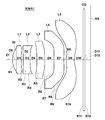
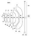
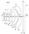
- FIG. 1 is a lens cross-sectional view illustrating a first configuration example of an imaging lens according to an embodiment of the present invention and corresponding to Example 1.
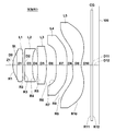
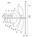
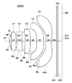
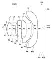
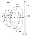
- FIG. FIG. 2 is a lens cross-sectional view illustrating a second configuration example of an imaging lens according to an embodiment of the present invention and corresponding to Example 2; 3 is a lens cross-sectional view illustrating a third configuration example of an imaging lens according to an embodiment of the present invention and corresponding to Example 3.
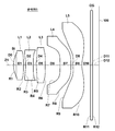
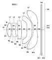
- FIG. 4 is a lens cross-sectional view illustrating a fourth configuration example of an imaging lens according to an embodiment of the present invention and corresponding to Reference Example 4.
- FIG. 5 is a lens cross-sectional view illustrating a fifth configuration example of an imaging lens according to an embodiment of the present invention and corresponding to Reference Example 5.
- FIG. 6 is a lens cross-sectional view illustrating a sixth configuration example of an imaging lens according to an embodiment of the present invention and corresponding to Example 6.
- FIG. 7 is a lens cross-sectional view illustrating a seventh configuration example of an imaging lens according to an embodiment of the present invention and corresponding to Example 7.
- FIG. 8 shows an eighth configuration example of the imaging lens according to an embodiment of the present invention, and is a lens cross-sectional view corresponding to Example 8.
- FIG. 9 is a lens cross-sectional view illustrating a ninth configuration example of an imaging lens according to an embodiment of the present invention and corresponding to Example 9.
- FIG. 10 is a lens cross-sectional view illustrating a tenth configuration example of an imaging lens according to an embodiment of the present invention and corresponding to Example 10.
- FIG. 11 shows an eleventh configuration example of the imaging lens according to the embodiment of the invention, and is a lens cross-sectional view corresponding to Example 11.
- FIG. 12 is a lens cross-sectional view illustrating a twelfth configuration example of an imaging lens according to an embodiment of the present invention and corresponding to Example 12.
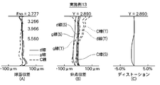
- FIG. 14 is a lens cross-sectional view illustrating a thirteenth configuration example of an imaging lens according to an embodiment of the present invention and corresponding to Example 13.
- FIG. 4A and 4B are aberration diagrams illustrating various aberrations of the imaging lens according to Example 1 of the present invention, in which (A) shows spherical aberration, (B) shows astigmatism (field curvature), and (C) shows distortion.
- FIG. 1 shows spherical aberration
- B shows astigmatism (field curvature)
- C shows distortion.
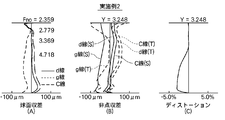
- FIG. 6 is an aberration diagram showing various aberrations of the imaging lens according to Example 2 of the present invention, in which (A) shows spherical aberration, (B) shows astigmatism (field curvature), and (C) shows distortion.
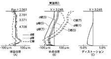
- FIG. 6 is an aberration diagram showing various aberrations of the imaging lens according to Example 3 of the present invention, in which (A) shows spherical aberration, (B) shows astigmatism (field curvature), and (C) shows distortion.
- It is an aberration diagram which shows the various aberrations of the imaging lens which concerns on the reference example 4 of this invention, (A) shows spherical aberration, (B) shows astigmatism (field curvature), (C) shows distortion aberration.
- FIG. 1 shows a first configuration example of an imaging lens according to an embodiment of the present invention.
- This configuration example corresponds to the lens configuration of a first numerical example (Tables 1 and 14) described later.
- cross-sectional configurations of second to third configuration examples corresponding to lens configurations of second to third numerical examples (Tables 2 to 3 and Tables 15 to 16) described later are shown in FIGS. 3 shows.
- 6 to 13 show cross-sectional configurations of the sixth to thirteenth configuration examples corresponding to the lens configurations of the sixth to thirteenth numerical examples (Tables 6 to 13 and Tables 19 to 26).
- 4 and 5 show cross-sectional configurations of the fourth and fifth reference examples (Tables 4 to 5 and Tables 17 to 18).
- the symbol Ri denotes the curvature of the i-th surface, where the surface of the lens element closest to the object side is the first, and is increased sequentially toward the image side (imaging side). Indicates the radius.
- the symbol Di indicates the surface interval on the optical axis Z1 between the i-th surface and the i + 1-th surface. Since the basic configuration is the same in each configuration example, the configuration example of the imaging lens shown in FIG. 1 will be basically described below, and FIGS. 2 to 3 and FIGS. 6 to 13 will be described as necessary. An example of the configuration will also be described.
- the imaging lens L includes various imaging devices using imaging elements such as CCDs and CMOSs, in particular, relatively small portable terminal devices such as digital still cameras, mobile phones with cameras, smartphones, tablet terminals, and the like. It is suitable for use in PDAs and the like.
- the imaging lens L includes a first lens L1, a second lens L2, a third lens L3, a fourth lens L4, and a fifth lens L5 in order from the object side along the optical axis Z1. Yes.
- FIG. 27 shows an overview of a mobile phone terminal that is the imaging apparatus 1 according to the present embodiment.
- the imaging apparatus 1 according to the present embodiment includes an imaging lens L according to the present embodiment and an imaging element 100 such as a CCD that outputs an imaging signal corresponding to an optical image formed by the imaging lens L (see FIG. 1). ).
- the image sensor 100 is disposed on the imaging surface (imaging surface) of the imaging lens L.
- FIG. 28 shows an overview of a smartphone that is the imaging device 501 according to the embodiment of the present invention.
- An image pickup apparatus 501 according to the embodiment of the present invention includes an image pickup lens L according to this embodiment and an image pickup device 100 such as a CCD that outputs an image pickup signal corresponding to an optical image formed by the image pickup lens L (see FIG. 1)).
- the image sensor 100 is disposed on the imaging surface (imaging surface) of the imaging lens L.
- Various optical members CG may be arranged between the fifth lens L5 and the image sensor 100 according to the configuration on the camera side where the lens is mounted.
- a flat optical member such as a cover glass for protecting the imaging surface or an infrared cut filter may be disposed.
- a flat cover glass provided with a coating having a filter effect such as an infrared cut filter or an ND filter may be used.
- the fifth lens L5 may be coated to have the same effect as the optical member CG. Thereby, the number of parts can be reduced and the total length can be shortened.
- the imaging lens L also has an aperture stop St.
- the aperture stop St is an optical aperture stop, and is preferably disposed before and after the first lens L1.
- the aperture stop St is a so-called “front stop” disposed on the most object side.
- the “front stop” means that the position of the aperture stop in the optical axis direction is at the same position as the intersection of the axial marginal ray and the object side surface of the first lens L1 or closer to the object side. .
- the lenses of the first to third configuration examples and the lenses of the sixth to thirteenth configuration examples are configuration examples corresponding to the front diaphragm. is there.
- This imaging lens L uses an aspherical surface on at least one surface of each of the first lens L1 to the fifth lens L5 for high performance.
- the first lens L1 has a positive power in the vicinity of the optical axis.
- the first lens L1 has a convex surface facing the object side in the vicinity of the optical axis. Thereby, it is possible to easily correct the spherical aberration.
- the second lens L2 has negative power in the vicinity of the optical axis.
- the second lens L2 has a concave surface facing the image side in the vicinity of the optical axis. Since the second lens L2 has a concave surface facing the image side in the vicinity of the optical axis, the curvature of field can be corrected well.
- the third lens L3 has a positive power in the vicinity of the optical axis.
- the fourth lens L4 has negative power in the vicinity of the optical axis.
- the “peripheral portion” of the fourth lens L4 has a shape such that a tangent line on the image side surface connects the intersection between the optical axis and the image side.
- the “peripheral portion” means a portion outside 50% of the effective diameter of the lens from the optical axis toward the outside in the radial direction of the lens.
- the fourth lens L4 has an image-side surface that is concave toward the image side in the vicinity of the optical axis, and a tangent line on the image-side surface at the periphery of the image-side surface is between the optical axis and the image side.
- the occurrence of longitudinal chromatic aberration and lateral chromatic aberration can be further reduced.
- the image-side surface of the fourth lens L4 but also the object-side surface has a shape in which the tangent line on the object-side surface forms an intersection between the optical axis and the image side in the periphery. The above effects are more remarkable.
- the fifth lens L5 is a meniscus lens having negative power near the optical axis.
- the fifth lens L5 has a concave surface facing the image side in the vicinity of the optical axis. As described above, the fifth lens has the concave surface facing the image side, so that the curvature of field can be corrected well.
- each of the lenses L1 to L5 constituting the imaging lens L is not a cemented lens but a single lens. For this reason, since the number of aspheric surfaces is larger than when any one of the lenses L1 to L5 is a cemented lens, the degree of freedom in designing each lens is increased, and the overall length can be suitably shortened.
- the Abbe number ⁇ d2 regarding the d-line of the second lens L2 satisfies the following conditional expression (1).
- ⁇ d2 ⁇ 35 (1)
- conditional expression (1) for the second lens L2 and decreasing the Abbe number ⁇ d2 and increasing the dispersion as a negative lens axial chromatic aberration can be corrected satisfactorily.
- the resolving power at the center of the image area can be suitably maintained.
- the focal length f3 of the third lens and the focal length f1 of the first lens satisfy the following conditional expression (2). 2 ⁇ f3 / f1 ⁇ 20 (2)
- the power of the first lens L1 is higher than the third lens L3. Since it becomes weaker and the focal length f1 of the first lens L1 becomes larger, the total lens length becomes longer. For this reason, the value of the focal length f3 of the third lens L3 and the focal length f1 of the first lens L1 satisfies the lower limit of the expression (2), so that the power of the first lens L1 is that of the third lens L3.
- the power of the first and third lenses can be balanced so as not to become too weak with respect to the power, and the focal length f1 of the first lens L1 is maintained within an appropriate range, so that the overall length can be shortened satisfactorily. Can do.
- the values of the focal length f3 of the third lens L3 and the focal length f1 of the first lens L1 exceed the upper limit of the expression (2), the first lens can be easily shortened. Since the power of L1 is stronger than the third lens L3, the difference in optical performance between the periphery of the imaging region and the center of the imaging region is increased, and the resolution performance at the periphery of the imaging region is deteriorated. .
- the value of the focal length f3 of the third lens L3 and the focal length f1 of the first lens L1 satisfies the upper limit of the expression (2), so that the power of the first lens L1 is that of the third lens L3. Since the power of the first and third lenses can be balanced so as not to become too strong with respect to the power, good optical performance can be realized from the center of the imaging region to the periphery of the imaging region. In this respect, it is more preferable to satisfy the conditional expression (2-1), and it is even more preferable to satisfy the conditional expression (2-2). 2.2 ⁇ f3 / f1 ⁇ 20 (2-1) 2.5 ⁇ f3 / f1 ⁇ 12 (2-2)
- the focal length f4 of the fifth lens and the focal length f5 of the fifth lens satisfy the following conditional expression (3). 1.10 ⁇
- the negative power of the fourth lens L4 is stronger than the negative power of the fifth lens L5.
- the power of the fourth lens L4 becomes the power of the fifth lens L5 by making the focal length f4 of the fourth lens L4 and the focal length f5 of the fifth lens L5 satisfy the lower limit of the expression (3).
- the powers of the fourth and fifth lenses can be balanced so as not to become too strong, so that the field curvature or lateral chromatic aberration of the fifth lens L5 can be corrected well.
- the tendency of the incident angle to the image sensor to increase as the image height increases is significant, and the incidence to the image sensor from the center image height to the peripheral image height is significant. It is preferable to prevent the angle from becoming too large to prevent problems such as a decrease in light receiving efficiency and color mixing due to an increase in the incident angle with respect to the image sensor.
- conditional expression (3-1) If the upper limit of the following conditional expression (3-1) is exceeded, it is difficult to sufficiently suppress an increase in the incident angle to the image sensor, particularly at an intermediate image height. For this reason, by satisfying the upper limit of conditional expression (3-1), it is possible to suitably suppress the incident angle on the image sensor from becoming too large at the intermediate image height, and to the image sensor from the center image height to the peripheral image height. An increase in the incident angle can be suitably suppressed. In this respect, it is more preferable to satisfy the conditional expression (3-2). 1.1 ⁇
- the Abbe number ⁇ d4 related to the d-line of the fourth lens satisfies the following conditional expression (4). ⁇ d4 ⁇ 35 (4) If the Abbe number ⁇ d4 related to the d-line of the fourth lens exceeds the upper limit of the conditional expression (4), it becomes difficult to maintain the performance of lateral chromatic aberration at the periphery of the imaging region while preferably shortening the total length. For this reason, when the Abbe number ⁇ d4 relating to the d-line of the fourth lens satisfies the conditional expression (4), the shortening of the total length can be suitably shortened, and the longitudinal chromatic aberration and the lateral chromatic aberration can be enhanced. In this respect, it is more preferable to satisfy the conditional expression (4-1), and it is even more preferable to satisfy the conditional expression (4-2). ⁇ d4 ⁇ 30 (4-1) ⁇ d4 ⁇ 25 (4-2)
- the configuration of the lens elements is optimized in the lens configuration of five as a whole, and the dispersion of the fourth lens is particularly appropriate.
- the ratio of the focal length of the third lens to the first lens and the ratio of the focal length of the fourth lens to the fifth lens are suitably set.
- a lens system that is well corrected and has high imaging performance from the central field angle to the peripheral field angle can be realized.
- the production suitability is good and higher imaging performance can be realized.
- the imaging signal corresponding to the optical image formed by the high-performance imaging lens L according to the present embodiment is output.
- a high-resolution captured image can be obtained up to the angle of view.
- Table 1 and Table 14 below show specific lens data corresponding to the configuration of the imaging lens shown in FIG.
- Table 1 shows basic lens data
- Table 14 shows data related to aspheric surfaces.
- the surface of the lens element closest to the object side is the first (aperture stop St is the 0th) and heads toward the image side.
- the value (mm) of the curvature radius of the i-th surface from the object side is shown in correspondence with the reference symbol Ri in FIG.
- the column of the surface interval Di indicates the interval (mm) on the optical axis between the i-th surface Si and the i + 1-th surface Si + 1 from the object side.
- the column Ndj the value of the refractive index for the d-line (587.56 nm) of the j-th optical element from the object side is shown.
- the column of ⁇ dj shows the Abbe number value for the d-line of the j-th optical element from the object side.
- both surfaces of the first lens L2 to the fifth lens L5 are all aspherical.
- the basic lens data in Table 1 shows the numerical value of the radius of curvature near the optical axis (paraxial radius of curvature) as the radius of curvature of these aspheric surfaces.
- Table 14 shows aspherical data in the imaging lens of Example 1.
- E indicates that the subsequent numerical value is a “power exponent” with a base of 10
- the numerical value represented by an exponential function with the base of 10 is Indicates that the value before “E” is multiplied.
- “1.0E-02” indicates “1.0 ⁇ 10 ⁇ 2”.
- Z is the length (mm) of a perpendicular line drawn from a point on the aspheric surface at a height h from the optical axis to the tangential plane (plane perpendicular to the optical axis) of the apex of the aspheric surface.
- Z C ⁇ h 2 / ⁇ 1+ (1 ⁇ K ⁇ C 2 ⁇ h 2) 1/2 ⁇ + ⁇ Ai ⁇ hi (A)
- Z Depth of aspheric surface (mm)
- h Distance from the optical axis to the lens surface (height) (mm)
- C: Paraxial curvature 1 / R (R: paraxial radius of curvature)
- K aspheric coefficient
- Example 2 Similar to the imaging lens of Example 1 above, specific lens data corresponding to the configuration of the imaging lens shown in FIG. 2 is shown as Example 2 in Tables 2 and 15, and the imaging shown in FIG. Specific lens data corresponding to the lens configuration is shown in Table 3 and Table 16 as Example 3. Similarly, specific lens data corresponding to the configuration of the imaging lens shown in FIGS. 6 to 13 is shown in Tables 6 to 13 and Tables 19 to 26 as Examples 6 to 13. Similarly, the lens data of the reference examples shown in FIGS. 4 and 5 are shown in Tables 4 to 5 and Tables 17 to 18. In the imaging lenses according to Examples 2 to 3 and Examples 6 to 13, both surfaces of the first lens L1 to the fifth lens L5 are all aspherical.
- Table 27 shows the values related to the above-described conditional expressions, which are summarized for each example and reference example.
- Table 27 shows values of the F number Fno and the focal length f (mm) of the entire system as various data.
- mm is used as the unit of length, but the optical system can be used with proportional expansion or proportional reduction. Other suitable units can also be used.
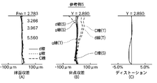
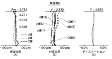
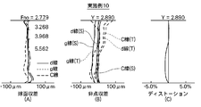
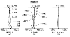
- each aberration diagram shows the aberration with the d-line (wavelength 587.56 nm) as the reference wavelength.
- the spherical aberration diagram and the astigmatism diagram also show aberrations for the g-line (wavelength 435.83 nm) and the C-line (wavelength 656.27 nm).
- the solid line indicates the sagittal direction (S)
- the broken line indicates the tangential direction (T).
- Fno represents the F number
- Y represents the image height (Y).
- FIGS. 18A to 18C show various aberrations of Reference Examples 4 and 5.
- each embodiment achieves high imaging performance as well as shortening the overall length.
- this invention is not limited to the said embodiment and each Example, Various deformation
- the values of the radius of curvature, the surface interval, the refractive index, the Abbe number, and the aspheric coefficient of each lens component are not limited to the values shown in the above numerical examples, and may take other values.
- the description is based on the premise that the fixed focus is used.
- the entire lens system can be extended, or a part of the lenses can be moved on the optical axis to enable autofocusing.
Landscapes
- Physics & Mathematics (AREA)
- General Physics & Mathematics (AREA)
- Optics & Photonics (AREA)
- Lenses (AREA)
Abstract
Le problème à résoudre dans le cadre de la présente invention consiste à réduire la longueur totale et à augmenter la résolution d'un objectif d'imagerie.
La solution consiste en cet objectif d'imagerie sensiblement formé de cinq lentilles comprenant, dans l'ordre depuis le côté de l'objet : une première lentille (L1) dotée d'une surface asphérique qui possède une puissance positive et une surface convexe faisant face au côté de l'objet ; une deuxième lentille (L2) dotée d'une surface asphérique qui possède une puissance négative et une surface concave faisant face au côté de l'image ; une troisième lentille (L3) dotée d'une surface asphérique qui possède une puissance positive ; une quatrième lentille (L4) dotée d'une surface asphérique qui possède une puissance négative ; et une cinquième lentille (L5) dotée d'une surface asphérique qui possède une surface convexe faisant face au côté de l'image et qui est un ménisque possédant une puissance négative. Cet objectif d'imagerie répond également aux conditions prescrites.
Priority Applications (4)
| Application Number | Priority Date | Filing Date | Title |
|---|---|---|---|
| JP2013525549A JP5827688B2 (ja) | 2011-07-25 | 2012-06-12 | 撮像レンズおよび撮像レンズを備えた撮像装置 |
| CN201280021189.1A CN103502868B (zh) | 2011-07-25 | 2012-06-12 | 摄像透镜和设置有该摄像透镜的摄像装置 |
| US14/062,913 US8810923B2 (en) | 2011-07-25 | 2013-10-25 | Image capturing lens and image capturing apparatus provided with the image capturing lens |
| US14/322,220 US9013809B2 (en) | 2011-07-25 | 2014-07-02 | Image capturing lens and image capturing apparatus provided with the image capturing lens |
Applications Claiming Priority (4)
| Application Number | Priority Date | Filing Date | Title |
|---|---|---|---|
| JP2011161507 | 2011-07-25 | ||
| JP2011-161507 | 2011-07-25 | ||
| JP2012-131656 | 2012-06-11 | ||
| JP2012131656 | 2012-06-11 |
Related Child Applications (1)
| Application Number | Title | Priority Date | Filing Date |
|---|---|---|---|
| US14/062,913 Continuation US8810923B2 (en) | 2011-07-25 | 2013-10-25 | Image capturing lens and image capturing apparatus provided with the image capturing lens |
Publications (1)
| Publication Number | Publication Date |
|---|---|
| WO2013014850A1 true WO2013014850A1 (fr) | 2013-01-31 |
Family
ID=47600728
Family Applications (1)
| Application Number | Title | Priority Date | Filing Date |
|---|---|---|---|
| PCT/JP2012/003822 Ceased WO2013014850A1 (fr) | 2011-07-25 | 2012-06-12 | Objectif d'imagerie et dispositif d'imagerie doté de celui-ci |
Country Status (4)
| Country | Link |
|---|---|
| US (2) | US8810923B2 (fr) |
| JP (1) | JP5827688B2 (fr) |
| CN (1) | CN103502868B (fr) |
| WO (1) | WO2013014850A1 (fr) |
Cited By (12)
| Publication number | Priority date | Publication date | Assignee | Title |
|---|---|---|---|---|
| JP2014153576A (ja) * | 2013-02-08 | 2014-08-25 | Konica Minolta Inc | 撮像レンズ、撮像装置及び携帯端末 |
| JP2014153712A (ja) * | 2013-02-06 | 2014-08-25 | Genius Electronic Optical Co | 撮像レンズ |
| JP2014153575A (ja) * | 2013-02-08 | 2014-08-25 | Konica Minolta Inc | 撮像レンズ、撮像装置及び携帯端末 |
| CN104345432A (zh) * | 2013-07-23 | 2015-02-11 | 大立光电股份有限公司 | 影像系统透镜组及取像装置 |
| EP2891912A1 (fr) * | 2014-01-02 | 2015-07-08 | Samsung Electro-Mechanics Co., Ltd. | Module de lentille |
| US9207435B2 (en) | 2013-12-18 | 2015-12-08 | Largan Precision Co., Ltd. | Imaging optical lens system, imaging device and mobile terminal |
| KR101578647B1 (ko) | 2014-08-11 | 2015-12-18 | 주식회사 코렌 | 촬영 렌즈 광학계 |
| JP2016018001A (ja) * | 2014-07-04 | 2016-02-01 | カンタツ株式会社 | 撮像レンズ |
| TWI553335B (zh) * | 2014-10-07 | 2016-10-11 | 先進光電科技股份有限公司 | 光學成像系統 |
| US9638894B2 (en) | 2014-08-12 | 2017-05-02 | Largan Precision Co., Ltd. | Photographing optical lens assembly, image capturing device and electronic device |
| JP2020013091A (ja) * | 2018-07-20 | 2020-01-23 | エーエーシー テクノロジーズ ピーティーイー リミテッド | 撮像光学レンズ |
| US12321038B2 (en) | 2015-07-24 | 2025-06-03 | Largan Precision Co., Ltd. | Optical photographing lens assembly, image capturing device and electronic device |
Families Citing this family (44)
| Publication number | Priority date | Publication date | Assignee | Title |
|---|---|---|---|---|
| JP5602305B2 (ja) * | 2011-06-15 | 2014-10-08 | 富士フイルム株式会社 | 撮像レンズおよび撮像レンズを備えた撮像装置 |
| TWI440884B (zh) | 2011-11-07 | 2014-06-11 | Largan Precision Co Ltd | 攝影系統 |
| TWI476435B (zh) * | 2013-03-20 | 2015-03-11 | Largan Precision Co Ltd | 結像鏡頭系統組 |
| CN105308947B (zh) | 2013-06-13 | 2018-10-02 | 核心光电有限公司 | 双孔径变焦数字摄影机 |
| CN105359006B (zh) | 2013-07-04 | 2018-06-22 | 核心光电有限公司 | 小型长焦透镜套件 |
| US9857568B2 (en) | 2013-07-04 | 2018-01-02 | Corephotonics Ltd. | Miniature telephoto lens assembly |
| CN105319674B (zh) * | 2014-06-10 | 2017-09-01 | 光燿科技股份有限公司 | 成像镜头组 |
| US9392188B2 (en) | 2014-08-10 | 2016-07-12 | Corephotonics Ltd. | Zoom dual-aperture camera with folded lens |
| KR102340793B1 (ko) * | 2014-10-20 | 2021-12-17 | 삼성전자주식회사 | 촬영 렌즈 및 이를 포함한 촬영 장치 |
| KR101719877B1 (ko) * | 2014-12-05 | 2017-03-24 | 삼성전기주식회사 | 렌즈 모듈 |
| WO2016108093A1 (fr) | 2015-01-03 | 2016-07-07 | Corephotonics Ltd. | Module de lentille de téléobjectif miniature et appareil photographique utilisant un tel module de lentille |
| TWI545365B (zh) | 2015-02-17 | 2016-08-11 | 大立光電股份有限公司 | 取像鏡頭組、取像裝置及電子裝置 |
| CN105988200B (zh) * | 2015-03-02 | 2018-09-28 | 大立光电股份有限公司 | 成像系统、取像装置及电子装置 |
| EP4560375A3 (fr) | 2017-02-23 | 2025-07-16 | Corephotonics Ltd. | Conceptions de lentilles de caméra pliées |
| WO2019008517A1 (fr) | 2017-07-07 | 2019-01-10 | Corephotonics Ltd | Conception de prisme d'appareil photo repliée destinée à empêcher une lumière parasite |
| KR102310641B1 (ko) | 2017-07-23 | 2021-10-08 | 코어포토닉스 리미티드 | 큰 애퍼처를 갖는 컴팩터형 폴디드 렌즈 |
| JP2019148615A (ja) * | 2018-02-26 | 2019-09-05 | O−FILM.Japan株式会社 | 撮像レンズおよび撮像装置 |
| KR102731629B1 (ko) | 2018-03-02 | 2024-11-21 | 코어포토닉스 리미티드 | 미광을 완화시키기 위한 스페이서 설계 |
| EP3765884A4 (fr) | 2018-05-14 | 2021-06-09 | Corephotonics Ltd. | Modèles de lentille de caméra pliée |
| CN114615400B (zh) | 2019-01-03 | 2024-11-15 | 核心光电有限公司 | 相机、双重相机及三重相机 |
| JP7570331B2 (ja) | 2019-02-25 | 2024-10-21 | コアフォトニクス リミテッド | 2つのズーム状態を有する少なくとも1つのカメラを備えるマルチアパーチャカメラ |
| CN119676548A (zh) | 2019-07-11 | 2025-03-21 | 华为技术有限公司 | 一种镜头、摄像头和电子设备 |
| WO2021027431A1 (fr) * | 2019-08-14 | 2021-02-18 | 宁波舜宇光电信息有限公司 | Ensemble de photographie sous-écran, module de photographie, caméra optique, et procédés de fabrication pour module de photographie et caméra optique |
| CN114578518B (zh) | 2019-08-21 | 2025-01-21 | 核心光电有限公司 | 镜头组件 |
| KR102534055B1 (ko) * | 2019-08-30 | 2023-05-19 | 삼성전기주식회사 | 촬상 광학계 및 이를 포함하는 휴대용 전자기기 |
| US12072609B2 (en) | 2019-09-24 | 2024-08-27 | Corephotonics Ltd. | Slim pop-out cameras and lenses for such cameras |
| US11656538B2 (en) | 2019-11-25 | 2023-05-23 | Corephotonics Ltd. | Folded zoom camera module with adaptive aperture |
| CN114667729B (zh) | 2020-01-08 | 2024-04-19 | 核心光电有限公司 | 多孔变焦数码摄像头及其使用方法 |
| CN117572549A (zh) | 2020-05-30 | 2024-02-20 | 核心光电有限公司 | 用于获得超微距图像的系统和方法 |
| EP4014083A4 (fr) | 2020-07-22 | 2022-09-21 | Corephotonics Ltd. | Modèles de lentille de caméra pliée |
| CN119376165A (zh) | 2020-07-31 | 2025-01-28 | 核心光电有限公司 | 相机 |
| EP4127788A4 (fr) | 2020-09-18 | 2024-06-19 | Corephotonics Ltd. | Caméra à zoom éjectable |
| CN114730065B (zh) | 2020-11-05 | 2023-05-16 | 核心光电有限公司 | 基于两个光路折叠元件视场扫描的扫描长焦摄影机 |
| EP4066036A4 (fr) | 2020-12-01 | 2023-01-25 | Corephotonics Ltd. | Caméra pliée avec facteur de zoom adaptatif en continu |
| KR102847366B1 (ko) | 2021-01-25 | 2025-08-14 | 코어포토닉스 리미티드 | 슬림 팝-아웃 와이드 카메라 렌즈 |
| KR102723968B1 (ko) | 2021-03-22 | 2024-10-29 | 코어포토닉스 리미티드 | 연속적으로 적응하는 줌 팩터를 갖는 폴디드 카메라 |
| EP4664177A3 (fr) | 2021-06-23 | 2026-01-07 | Corephotonics Ltd. | Caméras téléscopiques compactes |
| CN120178483A (zh) | 2021-09-23 | 2025-06-20 | 核心光电有限公司 | 大光圈连续变焦折叠长焦摄像头模块及移动装置 |
| CN119270473A (zh) | 2021-11-02 | 2025-01-07 | 核心光电有限公司 | 相机模块和移动装置 |
| EP4449182B1 (fr) | 2021-12-14 | 2026-05-06 | Corephotonics Ltd. | Télécaméras à balayage compact à grande ouverture |
| JP2025503262A (ja) | 2022-02-01 | 2025-01-30 | コアフォトニクス リミテッド | スリムポップアウトテレカメラレンズ |
| US12348870B2 (en) | 2022-04-09 | 2025-07-01 | Corephotonics Ltd. | Spin-out 360-degree camera for smartphone |
| US12368960B2 (en) | 2022-08-05 | 2025-07-22 | Corephotonics Ltd. | Systems and methods for zoom digital camera with automatic adjustable zoom field of view |
| CN120092456A (zh) | 2022-10-19 | 2025-06-03 | 核心光电有限公司 | 紧凑型折叠式相机 |
Citations (6)
| Publication number | Priority date | Publication date | Assignee | Title |
|---|---|---|---|---|
| JPS59121016A (ja) * | 1982-12-28 | 1984-07-12 | Konishiroku Photo Ind Co Ltd | 投影レンズ |
| JPS63274904A (ja) * | 1987-05-06 | 1988-11-11 | Minolta Camera Co Ltd | 前方絞りレンズ系 |
| JP2007264180A (ja) * | 2006-03-28 | 2007-10-11 | Fujinon Corp | 撮像レンズ |
| JP2007298572A (ja) * | 2006-04-27 | 2007-11-15 | Kyocera Corp | 撮像レンズ、光学モジュール、および携帯端末 |
| JP2010256608A (ja) * | 2009-04-24 | 2010-11-11 | Konica Minolta Opto Inc | 撮像レンズ,撮像光学装置及びデジタル機器 |
| JP2011085733A (ja) * | 2009-10-15 | 2011-04-28 | Hitachi Maxell Ltd | 撮像レンズ系 |
Family Cites Families (8)
| Publication number | Priority date | Publication date | Assignee | Title |
|---|---|---|---|---|
| JP4342591B1 (ja) | 2008-03-31 | 2009-10-14 | 株式会社東芝 | 光ディスク装置および制御方法 |
| JP5095662B2 (ja) * | 2009-03-31 | 2012-12-12 | カンタツ株式会社 | 固体撮像素子用撮像レンズ |
| CN101957492B (zh) * | 2009-07-14 | 2013-03-13 | 大立光电股份有限公司 | 摄影镜头 |
| TWI400506B (zh) | 2010-04-23 | 2013-07-01 | Largan Precision Co Ltd | 攝像光學鏡片組 |
| TWI438478B (zh) * | 2012-02-08 | 2014-05-21 | Largan Precision Co Ltd | 取像光學鏡片系統 |
| TWI439753B (zh) * | 2012-03-03 | 2014-06-01 | Largan Precision Co Ltd | 攝像光學鏡片系統 |
| TWI460463B (zh) * | 2012-05-28 | 2014-11-11 | Largan Precision Co Ltd | 拾像光學鏡片系統 |
| TWI467223B (zh) * | 2012-11-20 | 2015-01-01 | Largan Precision Co Ltd | 影像拾取系統鏡頭組 |
-
2012
- 2012-06-12 JP JP2013525549A patent/JP5827688B2/ja not_active Expired - Fee Related
- 2012-06-12 WO PCT/JP2012/003822 patent/WO2013014850A1/fr not_active Ceased
- 2012-06-12 CN CN201280021189.1A patent/CN103502868B/zh active Active
-
2013
- 2013-10-25 US US14/062,913 patent/US8810923B2/en active Active
-
2014
- 2014-07-02 US US14/322,220 patent/US9013809B2/en active Active
Patent Citations (6)
| Publication number | Priority date | Publication date | Assignee | Title |
|---|---|---|---|---|
| JPS59121016A (ja) * | 1982-12-28 | 1984-07-12 | Konishiroku Photo Ind Co Ltd | 投影レンズ |
| JPS63274904A (ja) * | 1987-05-06 | 1988-11-11 | Minolta Camera Co Ltd | 前方絞りレンズ系 |
| JP2007264180A (ja) * | 2006-03-28 | 2007-10-11 | Fujinon Corp | 撮像レンズ |
| JP2007298572A (ja) * | 2006-04-27 | 2007-11-15 | Kyocera Corp | 撮像レンズ、光学モジュール、および携帯端末 |
| JP2010256608A (ja) * | 2009-04-24 | 2010-11-11 | Konica Minolta Opto Inc | 撮像レンズ,撮像光学装置及びデジタル機器 |
| JP2011085733A (ja) * | 2009-10-15 | 2011-04-28 | Hitachi Maxell Ltd | 撮像レンズ系 |
Cited By (20)
| Publication number | Priority date | Publication date | Assignee | Title |
|---|---|---|---|---|
| JP2014153712A (ja) * | 2013-02-06 | 2014-08-25 | Genius Electronic Optical Co | 撮像レンズ |
| US9274314B2 (en) | 2013-02-06 | 2016-03-01 | Genius Electronic Optical Co., Ltd. | Imaging lens, and portable electronic apparatus including the same |
| JP2014153575A (ja) * | 2013-02-08 | 2014-08-25 | Konica Minolta Inc | 撮像レンズ、撮像装置及び携帯端末 |
| JP2014153576A (ja) * | 2013-02-08 | 2014-08-25 | Konica Minolta Inc | 撮像レンズ、撮像装置及び携帯端末 |
| CN104345432A (zh) * | 2013-07-23 | 2015-02-11 | 大立光电股份有限公司 | 影像系统透镜组及取像装置 |
| CN104345432B (zh) * | 2013-07-23 | 2017-01-18 | 大立光电股份有限公司 | 影像系统透镜组及取像装置 |
| US9207435B2 (en) | 2013-12-18 | 2015-12-08 | Largan Precision Co., Ltd. | Imaging optical lens system, imaging device and mobile terminal |
| CN104765129A (zh) * | 2014-01-02 | 2015-07-08 | 三星电机株式会社 | 镜头模块 |
| KR101598266B1 (ko) * | 2014-01-02 | 2016-02-26 | 삼성전기주식회사 | 렌즈 모듈 |
| KR20150080680A (ko) * | 2014-01-02 | 2015-07-10 | 삼성전기주식회사 | 렌즈 모듈 |
| US9310585B2 (en) | 2014-01-02 | 2016-04-12 | Samsung Electro-Mechanics Co., Ltd. | Lens module |
| EP2891912A1 (fr) * | 2014-01-02 | 2015-07-08 | Samsung Electro-Mechanics Co., Ltd. | Module de lentille |
| JP2016018001A (ja) * | 2014-07-04 | 2016-02-01 | カンタツ株式会社 | 撮像レンズ |
| US10185122B2 (en) | 2014-07-04 | 2019-01-22 | Kantatsu Co., Ltd. | Imaging lens |
| KR101578647B1 (ko) | 2014-08-11 | 2015-12-18 | 주식회사 코렌 | 촬영 렌즈 광학계 |
| US9405103B2 (en) | 2014-08-11 | 2016-08-02 | Kolen Co., Ltd. | Photographic lens optical system |
| US9638894B2 (en) | 2014-08-12 | 2017-05-02 | Largan Precision Co., Ltd. | Photographing optical lens assembly, image capturing device and electronic device |
| TWI553335B (zh) * | 2014-10-07 | 2016-10-11 | 先進光電科技股份有限公司 | 光學成像系統 |
| US12321038B2 (en) | 2015-07-24 | 2025-06-03 | Largan Precision Co., Ltd. | Optical photographing lens assembly, image capturing device and electronic device |
| JP2020013091A (ja) * | 2018-07-20 | 2020-01-23 | エーエーシー テクノロジーズ ピーティーイー リミテッド | 撮像光学レンズ |
Also Published As
| Publication number | Publication date |
|---|---|
| US20140049839A1 (en) | 2014-02-20 |
| US20140313597A1 (en) | 2014-10-23 |
| JP5827688B2 (ja) | 2015-12-02 |
| JPWO2013014850A1 (ja) | 2015-02-23 |
| US8810923B2 (en) | 2014-08-19 |
| CN103502868A (zh) | 2014-01-08 |
| US9013809B2 (en) | 2015-04-21 |
| CN103502868B (zh) | 2016-01-20 |
Similar Documents
| Publication | Publication Date | Title |
|---|---|---|
| JP5827688B2 (ja) | 撮像レンズおよび撮像レンズを備えた撮像装置 | |
| JP5823527B2 (ja) | 撮像レンズおよび撮像レンズを備えた撮像装置 | |
| JP5886230B2 (ja) | 撮像レンズおよび撮像レンズを備えた撮像装置 | |
| JP5698872B2 (ja) | 撮像レンズおよび撮像レンズを備えた撮像装置 | |
| JP5911819B2 (ja) | 撮像レンズおよび撮像レンズを備えた撮像装置 | |
| JP5602305B2 (ja) | 撮像レンズおよび撮像レンズを備えた撮像装置 | |
| JP5602299B2 (ja) | 撮像レンズおよび撮像レンズを備えた撮像装置 | |
| JP5687390B2 (ja) | 撮像レンズおよび撮像レンズを備えた撮像装置 | |
| JP5706584B2 (ja) | 撮像レンズおよび撮像レンズを備えた撮像装置 | |
| JP5800438B2 (ja) | 撮像レンズおよび撮像レンズを備えた撮像装置 | |
| JP5937036B2 (ja) | 撮像レンズおよび撮像レンズを備えた撮像装置 | |
| WO2013150755A1 (fr) | Lentille de capture d'images et dispositif de capture d'images comprenant la lentille de capture d'images | |
| JP2014240918A (ja) | 撮像レンズおよび撮像レンズを備えた撮像装置 | |
| WO2013161283A1 (fr) | Lentille d'imagerie et dispositif d'imagerie comprenant la lentille d'imagerie | |
| WO2014155460A1 (fr) | Lentille d'imagerie et dispositif d'imagerie muni d'une lentille d'imagerie | |
| JP5727679B2 (ja) | 撮像レンズおよび撮像レンズを備えた撮像装置 | |
| WO2014155459A1 (fr) | Lentille et dispositif de prise de vues muni d'une lentille de prise de vues | |
| JP5722507B2 (ja) | 撮像レンズおよび撮像レンズを備えた撮像装置 | |
| JP5718532B2 (ja) | 撮像レンズおよび撮像レンズを備えた撮像装置 | |
| WO2014103197A1 (fr) | Objectif d'imagerie et dispositif d'imagerie muni de l'objectif d'imagerie | |
| WO2014103199A1 (fr) | Objectif d'imagerie et dispositif d'imagerie muni de l'objectif d'imagerie | |
| WO2014155465A1 (fr) | Lentille et dispositif de prise de vues muni d'une lentille de prise de vues | |
| JP2014197104A (ja) | 撮像レンズおよび撮像レンズを備えた撮像装置 | |
| JP2014197096A (ja) | 撮像レンズおよび撮像レンズを備えた撮像装置 |
Legal Events
| Date | Code | Title | Description |
|---|---|---|---|
| 121 | Ep: the epo has been informed by wipo that ep was designated in this application |
Ref document number: 12818392 Country of ref document: EP Kind code of ref document: A1 |
|
| ENP | Entry into the national phase |
Ref document number: 2013525549 Country of ref document: JP Kind code of ref document: A |
|
| NENP | Non-entry into the national phase |
Ref country code: DE |
|
| 122 | Ep: pct application non-entry in european phase |
Ref document number: 12818392 Country of ref document: EP Kind code of ref document: A1 |