WO2013161283A1 - Lentille d'imagerie et dispositif d'imagerie comprenant la lentille d'imagerie - Google Patents
Lentille d'imagerie et dispositif d'imagerie comprenant la lentille d'imagerie Download PDFInfo
- Publication number
- WO2013161283A1 WO2013161283A1 PCT/JP2013/002740 JP2013002740W WO2013161283A1 WO 2013161283 A1 WO2013161283 A1 WO 2013161283A1 JP 2013002740 W JP2013002740 W JP 2013002740W WO 2013161283 A1 WO2013161283 A1 WO 2013161283A1
- Authority
- WO
- WIPO (PCT)
- Prior art keywords
- lens
- focal length
- imaging
- imaging lens
- conditional expression
- Prior art date
- Legal status (The legal status is an assumption and is not a legal conclusion. Google has not performed a legal analysis and makes no representation as to the accuracy of the status listed.)
- Ceased
Links
Images










Classifications
-
- G—PHYSICS
- G02—OPTICS
- G02B—OPTICAL ELEMENTS, SYSTEMS OR APPARATUS
- G02B13/00—Optical objectives specially designed for the purposes specified below
- G02B13/18—Optical objectives specially designed for the purposes specified below with lenses having one or more non-spherical faces, e.g. for reducing geometrical aberration
-
- G—PHYSICS
- G02—OPTICS
- G02B—OPTICAL ELEMENTS, SYSTEMS OR APPARATUS
- G02B13/00—Optical objectives specially designed for the purposes specified below
- G02B13/001—Miniaturised objectives for electronic devices, e.g. portable telephones, webcams, PDAs, small digital cameras
- G02B13/0015—Miniaturised objectives for electronic devices, e.g. portable telephones, webcams, PDAs, small digital cameras characterised by the lens design
- G02B13/002—Miniaturised objectives for electronic devices, e.g. portable telephones, webcams, PDAs, small digital cameras characterised by the lens design having at least one aspherical surface
- G02B13/0045—Miniaturised objectives for electronic devices, e.g. portable telephones, webcams, PDAs, small digital cameras characterised by the lens design having at least one aspherical surface having five or more lenses
Definitions
- each lens element is optimized in the lens configuration of five as a whole, and particularly the shapes of the third lens and the fifth lens are preferably configured, the overall length is shortened. A lens system having high resolution performance can be realized.
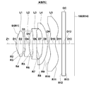
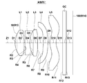
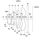
- FIG. 1 is a lens cross-sectional view illustrating a first configuration example of an imaging lens according to an embodiment of the present invention and corresponding to Example 1.
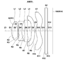
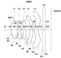
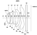
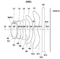
- FIG. FIG. 2 is a lens cross-sectional view illustrating a second configuration example of an imaging lens according to an embodiment of the present invention and corresponding to Example 2; 3 is a lens cross-sectional view illustrating a third configuration example of an imaging lens according to an embodiment of the present invention and corresponding to Example 3.
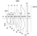
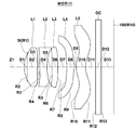
- FIG. 4 is a lens cross-sectional view illustrating a fourth configuration example of an imaging lens according to an embodiment of the present invention and corresponding to Example 4;
- FIG. 5 is a lens cross-sectional view illustrating a fifth configuration example of an imaging lens according to an embodiment of the present invention and corresponding to Example 5.
- FIG. 1 is a lens cross-sectional view illustrating a first configuration example of an imaging lens according to an embodiment of the present invention and corresponding to Example 1.
- FIG. FIG. 2 is a lens cross-sectional view illustrating a second configuration
- FIG. 6 is a lens cross-sectional view illustrating a sixth configuration example of an imaging lens according to an embodiment of the present invention and corresponding to Example 6.
- FIG. 7 is a lens cross-sectional view illustrating a seventh configuration example of an imaging lens according to an embodiment of the present invention and corresponding to Example 7.
- FIG. 8 shows an eighth configuration example of the imaging lens according to an embodiment of the present invention, and is a lens cross-sectional view corresponding to Example 8.
- FIG. 9 is a lens cross-sectional view illustrating a ninth configuration example of an imaging lens according to an embodiment of the present invention and corresponding to Example 9.
- FIG. 10 is a lens cross-sectional view illustrating a tenth configuration example of an imaging lens according to an embodiment of the present invention and corresponding to Example 10.
- FIG. 11 shows an eleventh configuration example of the imaging lens according to the embodiment of the invention, and is a lens cross-sectional view corresponding to Example 11.
- FIG. 12 is a lens cross-sectional view illustrating a twelfth configuration example of an imaging lens according to an embodiment of the present invention and corresponding to Example 12.
- FIG. 14 is a lens cross-sectional view illustrating a thirteenth configuration example of an imaging lens according to an embodiment of the present invention and corresponding to Example 13.
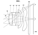
- FIG. It is a light ray diagram of the imaging lens shown in FIG. FIG.
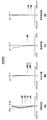
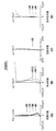
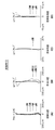
- FIG. 4 is an aberration diagram showing various aberrations of the imaging lens according to Example 1 of the present invention, in which (A) is spherical aberration, (B) is astigmatism (field curvature), (C) is distortion, and (D). Indicates lateral chromatic aberration.
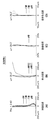
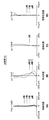
- It is an aberration diagram which shows the various aberrations of the imaging lens which concerns on Example 2 of this invention, (A) is spherical aberration, (B) is astigmatism (field curvature), (C) is distortion aberration, (D). Indicates lateral chromatic aberration.
- FIG. 3 It is an aberration diagram which shows the various aberrations of the imaging lens which concerns on Example 3 of this invention, (A) is spherical aberration, (B) is astigmatism (field curvature), (C) is a distortion aberration, (D). Indicates lateral chromatic aberration. It is an aberration diagram which shows the various aberrations of the imaging lens which concerns on Example 4 of this invention, (A) is spherical aberration, (B) is astigmatism (field curvature), (C) is distortion aberration, (D). Indicates lateral chromatic aberration.
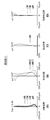
- FIG. 5 It is an aberration diagram which shows the various aberrations of the imaging lens which concerns on Example 5 of this invention, (A) is spherical aberration, (B) is astigmatism (field curvature), (C) is distortion aberration, (D). Indicates lateral chromatic aberration. It is an aberration diagram which shows the various aberrations of the imaging lens which concerns on Example 6 of this invention, (A) is spherical aberration, (B) is astigmatism (field curvature), (C) is distortion aberration, (D). Indicates lateral chromatic aberration.
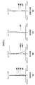
- FIG. 9 It is an aberration diagram showing various aberrations of the imaging lens according to Example 9 of the present invention, (A) is spherical aberration, (B) is astigmatism (field curvature), (C) is distortion, (D) Indicates lateral chromatic aberration. It is an aberration diagram which shows the various aberrations of the imaging lens which concerns on Example 10 of this invention, (A) is spherical aberration, (B) is astigmatism (field curvature), (C) is distortion aberration, (D). Indicates lateral chromatic aberration.
- FIG. 13 It is an aberration diagram showing various aberrations of the imaging lens according to Example 13 of the present invention, (A) is spherical aberration, (B) is astigmatism (field curvature), (C) is distortion, (D) Indicates lateral chromatic aberration.
- FIG. 1 shows a first configuration example of the imaging lens according to the first embodiment of the present invention.
- This configuration example corresponds to the lens configuration of a first numerical example (Tables 1 and 14) described later.
- cross-sectional configurations of second to thirteenth configuration examples corresponding to lens configurations of numerical examples (Tables 2 to 13 and Tables 15 to 26) according to second to thirteenth embodiments described later are shown.
- the symbol Ri denotes the curvature of the i-th surface, where the surface of the lens element closest to the object side is the first, and is increased sequentially toward the image side (imaging side). Indicates the radius.
- FIG. 14 is an optical path diagram of the imaging lens L shown in FIG. 1, and shows optical paths of the axial light beam 2 and the light beam 3 having the maximum field angle from an object point at an infinite distance.
- the imaging lens L includes various imaging devices using imaging elements such as CCDs and CMOSs, in particular, relatively small portable terminal devices such as digital still cameras, mobile phones with cameras, smartphones, tablets. It is suitable for use in type terminals and PDAs.
- the imaging lens L includes a first lens L1, a second lens L2, a third lens L3, a fourth lens L4, and a fifth lens L5 in order from the object side along the optical axis Z1. Yes.
- FIG. 28 shows an overview of a mobile phone terminal that is the imaging apparatus 1 according to the embodiment of the present invention.
- An imaging device 1 according to an embodiment of the present invention includes an imaging lens L according to the present embodiment and an imaging element 100 such as a CCD that outputs an imaging signal corresponding to an optical image formed by the imaging lens L (see FIG. 1).
- the image sensor 100 is disposed on the imaging surface (image surface R13) of the imaging lens L.
- the fifth lens L5 may be coated to have the same effect as the optical member CG. Thereby, the number of parts can be reduced and the total length can be shortened.
- the imaging lens L preferably further includes an aperture stop St disposed on the object side of the object side surface of the second lens L2.
- the aperture stop St is arranged on the object side of the object side surface of the second lens, so that the light beam passing through the optical system (imaging element), particularly in the periphery of the imaging region. An increase in the incident angle can be suppressed.
- the aperture stop St is disposed closer to the object side than the object side surface of the first lens in the optical axis direction.
- arranged closer to the object side than the object side surface of the second lens means that the position of the aperture stop in the optical axis direction is the same as the intersection of the axial marginal ray and the object side surface of the second lens L2. It means that it is on the object side.
- arranged closer to the object side than the object side surface of the first lens means that the position of the aperture stop in the optical axis direction is the same as the intersection of the axial marginal ray and the object side surface of the first lens L1. It means that it is on the object side.
- the lenses of the first to thirteenth configuration examples are configuration examples in which the aperture stop St is disposed closer to the object side than the image-side surface of the first lens L1.
- the aperture stop St is disposed on the image side with respect to the surface vertex of the first lens L1, but the present invention is not limited to this, and the aperture stop St is disposed on the object side with respect to the surface vertex of the first lens L1. It may be arranged.
- the aperture stop St is disposed on the object side with respect to the surface vertex of the first lens L1
- the amount of peripheral light is secured more than when the aperture stop St is disposed on the image side with respect to the surface vertex of the first lens L1.
- it is somewhat disadvantageous from this viewpoint it is possible to more suitably suppress an increase in the incident angle of the light beam passing through the optical system to the imaging surface (imaging device) in the peripheral portion of the imaging region.
- the first lens L1 has a positive refractive power in the vicinity of the optical axis. Further, like the imaging lens of the first embodiment shown in FIG. 1, it is preferable that the first lens L1 has a biconvex shape in the vicinity of the optical axis. When the first lens L1 has a biconvex shape, it is easy to correct spherical aberration.
- the third lens L3 has a positive refractive power in the vicinity of the optical axis.
- the third lens L3 has a convex surface facing the object side in the vicinity of the optical axis.
- the third lens L3 has a convex surface facing the object side in the vicinity of the optical axis.
- the third lens L3 has a meniscus shape with a convex surface facing the object side in the vicinity of the optical axis.
- the fourth lens L4 has a negative refractive power in the vicinity of the optical axis.
- the fourth lens L4 has a meniscus shape with a concave surface facing the object side in the vicinity of the optical axis.
- the fifth lens L5 has a positive refractive power in the vicinity of the optical axis.
- the fifth lens L5 has a meniscus shape with a convex surface facing the object side in the vicinity of the optical axis.
- the overall length can be suitably shortened, and the field curvature can be corrected well. can do.
- the image side surface has at least one inflection point within the effective diameter.
- the lenses described in Patent Documents 4 and 5 are based on the premise that astigmatism is corrected using an image rotation prism, and thus are used as a single imaging lens without using an image rotation prism. Astigmatism is difficult to correct, which is not preferable.
- the lenses described in Patent Documents 4 and 5 have a large F number. For example, a sufficiently small F number required for an imaging lens applied to a mobile phone terminal or the like can be taken even when the shooting environment is dark. It cannot be realized.
- the imaging lens according to the embodiment of the present invention has an F number smaller than the lenses described in Patent Documents 4 and 5, and can be suitably used even if the imaging lens does not include an image rotation prism. Therefore, it can be suitably applied to, for example, a mobile phone terminal.
- each of the lenses L1 to L5 constituting the imaging lens L is a single lens instead of a cemented lens. This is because the number of aspheric surfaces is larger than when any one of the lenses L1 to L5 is a cemented lens, so that the degree of freedom in designing each lens is increased, and the overall length can be suitably shortened.
- conditional expression (4) When the upper limit of conditional expression (4) is exceeded, astigmatism tends to be under, particularly at low angles of view. For this reason, astigmatism can be suitably corrected by satisfying the range of conditional expression (4). In order to further enhance this effect, it is more preferable to satisfy the conditional expression (4-1). -2.5 ⁇ (R6-R7) / (R6 + R7) ⁇ 0.05 (4-1)
- conditional expression (6) If the upper limit of conditional expression (6) is exceeded, the refractive power of the second lens L2 becomes too weak with respect to the refractive power of the entire system, making it difficult to correct lateral chromatic aberration. For this reason, spherical aberration and lateral chromatic aberration can be suitably corrected by satisfying the range of conditional expression (6). In order to enhance this effect, it is more preferable to satisfy the conditional expression (6-1), and it is even more preferable to satisfy the conditional expression (5-2). ⁇ 1 ⁇ f / f2 ⁇ 0.55 (6-1) ⁇ 0.9 ⁇ f / f2 ⁇ 0.63 (6-2)
- conditional expression (7) defines a preferable numerical range of the ratio of the focal length f of the entire system to the focal length f4 of the fourth lens L4. If the lower limit of conditional expression (7) is not reached, the refractive power of the fourth lens L4 becomes too strong with respect to the refractive power of the entire system, making it difficult to correct spherical aberration.
- conditional expression (1) defines a preferable numerical range of the ratio of the focal length f of the entire system to the focal length f5 of the fifth lens L5. If the lower limit of conditional expression (8) is not reached, it is difficult to correct astigmatism. If the upper limit of conditional expression (8) is exceeded, the refractive power of the fifth lens L5 becomes too strong with respect to the refractive power of the entire system, making it difficult to shorten the overall length.
- conditional expression (9) defines a preferable numerical range of the ratio of the focal length f of the entire system to the combined focal length f123 from the first lens to the third lens. If the lower limit of conditional expression (9) is not reached, the refractive power of the three lenses from the first lens L1 to the third lens L3 becomes too weak with respect to the refractive power of the entire system, and astigmatism is corrected. It becomes difficult and shortening of the total length becomes difficult to realize.
- the lens configuration of the first lens L1, the fourth lens L4, and the fifth lens L5 is the same as that of the first embodiment, and the fourth embodiment and the fourth lens L5.
- the lens configuration of the two lenses L2 may be made common, and the imaging lens L may be configured by sharing the configuration of the lenses of the fifth embodiment and the third lens L3. According to the configurations of the first to fifth lenses of the sixth embodiment, the same operational effects as the corresponding configurations of the first, fourth, and fifth embodiments can be obtained.
- the lens configuration of the third embodiment and the first lens L1 is the same, and the lenses of the eighth embodiment and the second lens L2 to the fifth lens L5 are shared.
- the imaging lens L may be configured with the same configuration. According to the configurations of the first to fifth lenses of the twelfth embodiment, the same operational effects as the corresponding configurations of the third and eighth embodiments can be obtained.
- FIGS. 15A to 15D are diagrams showing spherical aberration, astigmatism, distortion (distortion aberration), and lateral chromatic aberration (chromatic aberration of magnification) in the imaging lens of Example 1, respectively.
- Each aberration diagram showing spherical aberration, astigmatism (field curvature) and distortion (distortion aberration) shows aberrations with the d-line (wavelength 587.56 nm) as the reference wavelength.
- the spherical aberration diagram and the lateral chromatic aberration diagram also show aberrations for the F-line (wavelength 486.1 nm) and the C-line (wavelength 656.27 nm).
- the imaging lens of the present invention is not limited to the embodiment and each example, and various modifications can be made.
- the values of the radius of curvature, the surface interval, the refractive index, the Abbe number, and the aspherical coefficient of each lens component are not limited to the values shown in the numerical examples, but may take other values.
- the description is based on the premise that the fixed focus is used.
- the entire lens system can be extended, or a part of the lenses can be moved on the optical axis to enable autofocusing.
Landscapes
- Physics & Mathematics (AREA)
- General Physics & Mathematics (AREA)
- Optics & Photonics (AREA)
- Lenses (AREA)
Priority Applications (3)
| Application Number | Priority Date | Filing Date | Title |
|---|---|---|---|
| CN201390000131.9U CN203811883U (zh) | 2012-04-27 | 2013-04-23 | 成像透镜和配备有该成像透镜的成像设备 |
| JP2014512362A JP5785324B2 (ja) | 2012-04-27 | 2013-04-23 | 撮像レンズおよび撮像レンズを備えた撮像装置 |
| US14/208,839 US8982478B2 (en) | 2012-04-27 | 2014-03-13 | Imaging lens and imaging apparatus equipped with the imaging lens |
Applications Claiming Priority (4)
| Application Number | Priority Date | Filing Date | Title |
|---|---|---|---|
| JP2012102047 | 2012-04-27 | ||
| JP2012-102047 | 2012-04-27 | ||
| US201261660005P | 2012-06-15 | 2012-06-15 | |
| US61/660,005 | 2012-06-15 |
Related Child Applications (1)
| Application Number | Title | Priority Date | Filing Date |
|---|---|---|---|
| US14/208,839 Continuation US8982478B2 (en) | 2012-04-27 | 2014-03-13 | Imaging lens and imaging apparatus equipped with the imaging lens |
Publications (1)
| Publication Number | Publication Date |
|---|---|
| WO2013161283A1 true WO2013161283A1 (fr) | 2013-10-31 |
Family
ID=49482626
Family Applications (1)
| Application Number | Title | Priority Date | Filing Date |
|---|---|---|---|
| PCT/JP2013/002740 Ceased WO2013161283A1 (fr) | 2012-04-27 | 2013-04-23 | Lentille d'imagerie et dispositif d'imagerie comprenant la lentille d'imagerie |
Country Status (5)
| Country | Link |
|---|---|
| US (1) | US8982478B2 (fr) |
| JP (1) | JP5785324B2 (fr) |
| CN (1) | CN203811883U (fr) |
| TW (1) | TWM464678U (fr) |
| WO (1) | WO2013161283A1 (fr) |
Cited By (2)
| Publication number | Priority date | Publication date | Assignee | Title |
|---|---|---|---|---|
| US10809494B2 (en) | 2017-01-20 | 2020-10-20 | Kantatsu Co., Ltd. | Imaging lens |
| JP6991695B1 (ja) | 2020-09-22 | 2022-01-12 | レイテック オプティカル (ジョウシュウ) カンパニーリミテッド | 撮像光学レンズ |
Families Citing this family (16)
| Publication number | Priority date | Publication date | Assignee | Title |
|---|---|---|---|---|
| KR102060658B1 (ko) * | 2012-07-25 | 2019-12-30 | 삼성전자주식회사 | 촬상 렌즈 및 이를 포함한 촬상 장치 |
| WO2014155468A1 (fr) * | 2013-03-25 | 2014-10-02 | 富士フイルム株式会社 | Objectif d'imagerie et dispositif d'imagerie équipé d'objectif d'imagerie |
| CN205229553U (zh) * | 2013-03-26 | 2016-05-11 | 富士胶片株式会社 | 摄像透镜以及具备摄像透镜的摄像装置 |
| JP2015125212A (ja) * | 2013-12-26 | 2015-07-06 | ソニー株式会社 | 撮像レンズおよび撮像装置 |
| JP2015132687A (ja) * | 2014-01-10 | 2015-07-23 | 富士フイルム株式会社 | 撮像レンズおよび撮像レンズを備えた撮像装置 |
| KR102737556B1 (ko) | 2016-08-24 | 2024-12-03 | 삼성전기주식회사 | 촬상 광학계 |
| JP6808680B2 (ja) | 2017-05-31 | 2021-01-06 | キヤノン株式会社 | マウント装置、撮像装置、アダプタ装置およびアクセサリ |
| TWI771631B (zh) | 2017-05-31 | 2022-07-21 | 日商佳能股份有限公司 | 安裝設備及用於成像設備的配件 |
| RU2724459C2 (ru) * | 2017-05-31 | 2020-06-23 | Кэнон Кабусики Кайся | Устройство объектива, устройство захвата изображений, на котором может устанавливаться устройство объектива, и система камеры |
| RU2724453C2 (ru) | 2017-05-31 | 2020-06-23 | Кэнон Кабусики Кайся | Устройство объектива, устройство захвата изображений, на котором может устанавливаться устройство объектива, и система камеры |
| SG10202103518RA (en) | 2017-05-31 | 2021-05-28 | Canon Kk | Adapter device, imaging apparatus, and accessory |
| JP6622852B2 (ja) | 2017-05-31 | 2019-12-18 | キヤノン株式会社 | アクセサリ及びこれを装着可能な撮像装置、撮像システム |
| CN208386721U (zh) | 2017-05-31 | 2019-01-15 | 佳能株式会社 | 配件、能够安装该配件的摄像设备及相机系统 |
| KR102534055B1 (ko) * | 2019-08-30 | 2023-05-19 | 삼성전기주식회사 | 촬상 광학계 및 이를 포함하는 휴대용 전자기기 |
| TWI710794B (zh) * | 2020-03-30 | 2020-11-21 | 大立光電股份有限公司 | 成像用光學透鏡組、取像裝置及電子裝置 |
| CN114815188B (zh) * | 2021-01-27 | 2023-12-01 | 浙江舜宇光学有限公司 | 光学测试系统 |
Citations (5)
| Publication number | Priority date | Publication date | Assignee | Title |
|---|---|---|---|---|
| JPS5833211A (ja) * | 1981-08-21 | 1983-02-26 | Canon Inc | 小型の写真レンズ |
| JPS63116112A (ja) * | 1986-11-04 | 1988-05-20 | Minolta Camera Co Ltd | マイクロフイルム用投影レンズ |
| JPS63274904A (ja) * | 1987-05-06 | 1988-11-11 | Minolta Camera Co Ltd | 前方絞りレンズ系 |
| JP2005164839A (ja) * | 2003-12-01 | 2005-06-23 | Canon Inc | レンズ系及びそれを有する画像投影装置 |
| JP2006343554A (ja) * | 2005-06-09 | 2006-12-21 | Konica Minolta Photo Imaging Inc | 撮影レンズユニット |
Family Cites Families (5)
| Publication number | Priority date | Publication date | Assignee | Title |
|---|---|---|---|---|
| TWI271541B (en) | 2005-11-24 | 2007-01-21 | Largan Precision Co Ltd | Double focus lens and a portable machine with aforesaid lens |
| JP5426313B2 (ja) | 2009-10-15 | 2014-02-26 | 日立マクセル株式会社 | 撮像レンズ系 |
| JP2011133062A (ja) | 2009-12-25 | 2011-07-07 | Nsk Ltd | 転がり軸受 |
| TWI435135B (zh) * | 2010-10-06 | 2014-04-21 | Largan Precision Co Ltd | 光學透鏡系統 |
| JP5602305B2 (ja) * | 2011-06-15 | 2014-10-08 | 富士フイルム株式会社 | 撮像レンズおよび撮像レンズを備えた撮像装置 |
-
2013
- 2013-04-23 CN CN201390000131.9U patent/CN203811883U/zh not_active Expired - Lifetime
- 2013-04-23 JP JP2014512362A patent/JP5785324B2/ja not_active Expired - Fee Related
- 2013-04-23 WO PCT/JP2013/002740 patent/WO2013161283A1/fr not_active Ceased
- 2013-04-26 TW TW102207654U patent/TWM464678U/zh not_active IP Right Cessation
-
2014
- 2014-03-13 US US14/208,839 patent/US8982478B2/en active Active
Patent Citations (5)
| Publication number | Priority date | Publication date | Assignee | Title |
|---|---|---|---|---|
| JPS5833211A (ja) * | 1981-08-21 | 1983-02-26 | Canon Inc | 小型の写真レンズ |
| JPS63116112A (ja) * | 1986-11-04 | 1988-05-20 | Minolta Camera Co Ltd | マイクロフイルム用投影レンズ |
| JPS63274904A (ja) * | 1987-05-06 | 1988-11-11 | Minolta Camera Co Ltd | 前方絞りレンズ系 |
| JP2005164839A (ja) * | 2003-12-01 | 2005-06-23 | Canon Inc | レンズ系及びそれを有する画像投影装置 |
| JP2006343554A (ja) * | 2005-06-09 | 2006-12-21 | Konica Minolta Photo Imaging Inc | 撮影レンズユニット |
Cited By (4)
| Publication number | Priority date | Publication date | Assignee | Title |
|---|---|---|---|---|
| US10809494B2 (en) | 2017-01-20 | 2020-10-20 | Kantatsu Co., Ltd. | Imaging lens |
| US11774720B2 (en) | 2017-01-20 | 2023-10-03 | Tokyo Visionary Optics Co., Ltd. | Imaging lens |
| JP6991695B1 (ja) | 2020-09-22 | 2022-01-12 | レイテック オプティカル (ジョウシュウ) カンパニーリミテッド | 撮像光学レンズ |
| JP2022051649A (ja) * | 2020-09-22 | 2022-04-01 | レイテック オプティカル (ジョウシュウ) カンパニーリミテッド | 撮像光学レンズ |
Also Published As
| Publication number | Publication date |
|---|---|
| US8982478B2 (en) | 2015-03-17 |
| US20140192423A1 (en) | 2014-07-10 |
| CN203811883U (zh) | 2014-09-03 |
| TWM464678U (zh) | 2013-11-01 |
| JP5785324B2 (ja) | 2015-09-30 |
| JPWO2013161283A1 (ja) | 2015-12-21 |
Similar Documents
| Publication | Publication Date | Title |
|---|---|---|
| JP5785324B2 (ja) | 撮像レンズおよび撮像レンズを備えた撮像装置 | |
| JP5735712B2 (ja) | 撮像レンズおよび撮像レンズを備えた撮像装置 | |
| JP5886230B2 (ja) | 撮像レンズおよび撮像レンズを備えた撮像装置 | |
| JP6000179B2 (ja) | 撮像レンズおよび撮像レンズを備えた撮像装置 | |
| JP5752856B2 (ja) | 撮像レンズおよび撮像レンズを備えた撮像装置 | |
| JP5911819B2 (ja) | 撮像レンズおよび撮像レンズを備えた撮像装置 | |
| JP5687390B2 (ja) | 撮像レンズおよび撮像レンズを備えた撮像装置 | |
| JP5937035B2 (ja) | 撮像レンズおよび撮像レンズを備えた撮像装置 | |
| JP5937036B2 (ja) | 撮像レンズおよび撮像レンズを備えた撮像装置 | |
| WO2013145547A1 (fr) | Lentille d'imagerie et dispositif d'imagerie comportant une lentille d'imagerie | |
| JP2014240918A (ja) | 撮像レンズおよび撮像レンズを備えた撮像装置 | |
| JP2014209163A (ja) | 撮像レンズおよび撮像レンズを備えた撮像装置 | |
| JP2015022145A (ja) | 撮像レンズおよび撮像レンズを備えた撮像装置 | |
| JP6150317B2 (ja) | 撮像レンズおよび撮像レンズを備えた撮像装置 | |
| WO2014006822A1 (fr) | Lentille de recueil d'image et appareil de recueil d'image équipé de la lentille | |
| WO2014155467A1 (fr) | Objectif d'imagerie et dispositif d'imagerie muni de l'objectif d'imagerie | |
| WO2013175783A1 (fr) | Lentille d'imagerie et dispositif d'imagerie équipé d'une lentille d'imagerie | |
| WO2014155460A1 (fr) | Lentille d'imagerie et dispositif d'imagerie muni d'une lentille d'imagerie | |
| JP5727679B2 (ja) | 撮像レンズおよび撮像レンズを備えた撮像装置 | |
| WO2014155459A1 (fr) | Lentille et dispositif de prise de vues muni d'une lentille de prise de vues | |
| WO2014103198A1 (fr) | Objectif d'imagerie et dispositif d'imagerie muni de l'objectif d'imagerie | |
| JP5722507B2 (ja) | 撮像レンズおよび撮像レンズを備えた撮像装置 | |
| WO2014103197A1 (fr) | Objectif d'imagerie et dispositif d'imagerie muni de l'objectif d'imagerie | |
| JP5946790B2 (ja) | 撮像レンズおよび撮像レンズを備えた撮像装置 | |
| WO2014103199A1 (fr) | Objectif d'imagerie et dispositif d'imagerie muni de l'objectif d'imagerie |
Legal Events
| Date | Code | Title | Description |
|---|---|---|---|
| WWE | Wipo information: entry into national phase |
Ref document number: 201390000131.9 Country of ref document: CN |
|
| ENP | Entry into the national phase |
Ref document number: 2014512362 Country of ref document: JP Kind code of ref document: A |
|
| 121 | Ep: the epo has been informed by wipo that ep was designated in this application |
Ref document number: 13781876 Country of ref document: EP Kind code of ref document: A1 |
|
| NENP | Non-entry into the national phase |
Ref country code: DE |
|
| 122 | Ep: pct application non-entry in european phase |
Ref document number: 13781876 Country of ref document: EP Kind code of ref document: A1 |