WO2013018660A1 - Unité d'échange de chaleur, et système d'absorption/de rayonnement de chaleur utilisant celle-ci pour un panneau de batteries solaires - Google Patents
Unité d'échange de chaleur, et système d'absorption/de rayonnement de chaleur utilisant celle-ci pour un panneau de batteries solaires Download PDFInfo
- Publication number
- WO2013018660A1 WO2013018660A1 PCT/JP2012/069031 JP2012069031W WO2013018660A1 WO 2013018660 A1 WO2013018660 A1 WO 2013018660A1 JP 2012069031 W JP2012069031 W JP 2012069031W WO 2013018660 A1 WO2013018660 A1 WO 2013018660A1
- Authority
- WO
- WIPO (PCT)
- Prior art keywords
- heat
- pipe
- solar cell
- heat medium
- cell panel
- Prior art date
- Legal status (The legal status is an assumption and is not a legal conclusion. Google has not performed a legal analysis and makes no representation as to the accuracy of the status listed.)
- Ceased
Links
Images





Classifications
-
- F—MECHANICAL ENGINEERING; LIGHTING; HEATING; WEAPONS; BLASTING
- F28—HEAT EXCHANGE IN GENERAL
- F28D—HEAT-EXCHANGE APPARATUS, NOT PROVIDED FOR IN ANOTHER SUBCLASS, IN WHICH THE HEAT-EXCHANGE MEDIA DO NOT COME INTO DIRECT CONTACT
- F28D20/00—Heat storage plants or apparatus in general; Regenerative heat-exchange apparatus not covered by groups F28D17/00 or F28D19/00
- F28D20/0052—Heat storage plants or apparatus in general; Regenerative heat-exchange apparatus not covered by groups F28D17/00 or F28D19/00 using the ground body or aquifers as heat storage medium
-
- F—MECHANICAL ENGINEERING; LIGHTING; HEATING; WEAPONS; BLASTING
- F24—HEATING; RANGES; VENTILATING
- F24S—SOLAR HEAT COLLECTORS; SOLAR HEAT SYSTEMS
- F24S10/00—Solar heat collectors using working fluids
- F24S10/70—Solar heat collectors using working fluids the working fluids being conveyed through tubular absorbing conduits
- F24S10/75—Solar heat collectors using working fluids the working fluids being conveyed through tubular absorbing conduits with enlarged surfaces, e.g. with protrusions or corrugations
- F24S10/753—Solar heat collectors using working fluids the working fluids being conveyed through tubular absorbing conduits with enlarged surfaces, e.g. with protrusions or corrugations the conduits being parallel to each other
-
- F—MECHANICAL ENGINEERING; LIGHTING; HEATING; WEAPONS; BLASTING
- F24—HEATING; RANGES; VENTILATING
- F24S—SOLAR HEAT COLLECTORS; SOLAR HEAT SYSTEMS
- F24S10/00—Solar heat collectors using working fluids
- F24S10/90—Solar heat collectors using working fluids using internal thermosiphonic circulation
- F24S10/95—Solar heat collectors using working fluids using internal thermosiphonic circulation having evaporator sections and condenser sections, e.g. heat pipes
-
- F—MECHANICAL ENGINEERING; LIGHTING; HEATING; WEAPONS; BLASTING
- F24—HEATING; RANGES; VENTILATING
- F24S—SOLAR HEAT COLLECTORS; SOLAR HEAT SYSTEMS
- F24S40/00—Safety or protection arrangements of solar heat collectors; Preventing malfunction of solar heat collectors
- F24S40/20—Cleaning; Removing snow
-
- F—MECHANICAL ENGINEERING; LIGHTING; HEATING; WEAPONS; BLASTING
- F24—HEATING; RANGES; VENTILATING
- F24S—SOLAR HEAT COLLECTORS; SOLAR HEAT SYSTEMS
- F24S80/00—Details, accessories or component parts of solar heat collectors not provided for in groups F24S10/00-F24S70/00
- F24S80/30—Arrangements for connecting the fluid circuits of solar collectors with each other or with other components, e.g. pipe connections; Fluid distributing means, e.g. headers
-
- F—MECHANICAL ENGINEERING; LIGHTING; HEATING; WEAPONS; BLASTING
- F24—HEATING; RANGES; VENTILATING
- F24T—GEOTHERMAL COLLECTORS; GEOTHERMAL SYSTEMS
- F24T10/00—Geothermal collectors
- F24T10/10—Geothermal collectors with circulation of working fluids through underground channels, the working fluids not coming into direct contact with the ground
- F24T10/13—Geothermal collectors with circulation of working fluids through underground channels, the working fluids not coming into direct contact with the ground using tube assemblies suitable for insertion into boreholes in the ground, e.g. geothermal probes
- F24T10/15—Geothermal collectors with circulation of working fluids through underground channels, the working fluids not coming into direct contact with the ground using tube assemblies suitable for insertion into boreholes in the ground, e.g. geothermal probes using bent tubes; using tubes assembled with connectors or with return headers
-
- H—ELECTRICITY
- H02—GENERATION; CONVERSION OR DISTRIBUTION OF ELECTRIC POWER
- H02S—GENERATION OF ELECTRIC POWER BY CONVERSION OF INFRARED RADIATION, VISIBLE LIGHT OR ULTRAVIOLET LIGHT, e.g. USING PHOTOVOLTAIC [PV] MODULES
- H02S40/00—Components or accessories in combination with PV modules, not provided for in groups H02S10/00 - H02S30/00
- H02S40/40—Thermal components
- H02S40/44—Means to utilise heat energy, e.g. hybrid systems producing warm water and electricity at the same time
-
- Y—GENERAL TAGGING OF NEW TECHNOLOGICAL DEVELOPMENTS; GENERAL TAGGING OF CROSS-SECTIONAL TECHNOLOGIES SPANNING OVER SEVERAL SECTIONS OF THE IPC; TECHNICAL SUBJECTS COVERED BY FORMER USPC CROSS-REFERENCE ART COLLECTIONS [XRACs] AND DIGESTS
- Y02—TECHNOLOGIES OR APPLICATIONS FOR MITIGATION OR ADAPTATION AGAINST CLIMATE CHANGE
- Y02B—CLIMATE CHANGE MITIGATION TECHNOLOGIES RELATED TO BUILDINGS, e.g. HOUSING, HOUSE APPLIANCES OR RELATED END-USER APPLICATIONS
- Y02B10/00—Integration of renewable energy sources in buildings
- Y02B10/10—Photovoltaic [PV]
-
- Y—GENERAL TAGGING OF NEW TECHNOLOGICAL DEVELOPMENTS; GENERAL TAGGING OF CROSS-SECTIONAL TECHNOLOGIES SPANNING OVER SEVERAL SECTIONS OF THE IPC; TECHNICAL SUBJECTS COVERED BY FORMER USPC CROSS-REFERENCE ART COLLECTIONS [XRACs] AND DIGESTS
- Y02—TECHNOLOGIES OR APPLICATIONS FOR MITIGATION OR ADAPTATION AGAINST CLIMATE CHANGE
- Y02E—REDUCTION OF GREENHOUSE GAS [GHG] EMISSIONS, RELATED TO ENERGY GENERATION, TRANSMISSION OR DISTRIBUTION
- Y02E10/00—Energy generation through renewable energy sources
- Y02E10/10—Geothermal energy
-
- Y—GENERAL TAGGING OF NEW TECHNOLOGICAL DEVELOPMENTS; GENERAL TAGGING OF CROSS-SECTIONAL TECHNOLOGIES SPANNING OVER SEVERAL SECTIONS OF THE IPC; TECHNICAL SUBJECTS COVERED BY FORMER USPC CROSS-REFERENCE ART COLLECTIONS [XRACs] AND DIGESTS
- Y02—TECHNOLOGIES OR APPLICATIONS FOR MITIGATION OR ADAPTATION AGAINST CLIMATE CHANGE
- Y02E—REDUCTION OF GREENHOUSE GAS [GHG] EMISSIONS, RELATED TO ENERGY GENERATION, TRANSMISSION OR DISTRIBUTION
- Y02E10/00—Energy generation through renewable energy sources
- Y02E10/40—Solar thermal energy, e.g. solar towers
- Y02E10/44—Heat exchange systems
-
- Y—GENERAL TAGGING OF NEW TECHNOLOGICAL DEVELOPMENTS; GENERAL TAGGING OF CROSS-SECTIONAL TECHNOLOGIES SPANNING OVER SEVERAL SECTIONS OF THE IPC; TECHNICAL SUBJECTS COVERED BY FORMER USPC CROSS-REFERENCE ART COLLECTIONS [XRACs] AND DIGESTS
- Y02—TECHNOLOGIES OR APPLICATIONS FOR MITIGATION OR ADAPTATION AGAINST CLIMATE CHANGE
- Y02E—REDUCTION OF GREENHOUSE GAS [GHG] EMISSIONS, RELATED TO ENERGY GENERATION, TRANSMISSION OR DISTRIBUTION
- Y02E10/00—Energy generation through renewable energy sources
- Y02E10/50—Photovoltaic [PV] energy
-
- Y—GENERAL TAGGING OF NEW TECHNOLOGICAL DEVELOPMENTS; GENERAL TAGGING OF CROSS-SECTIONAL TECHNOLOGIES SPANNING OVER SEVERAL SECTIONS OF THE IPC; TECHNICAL SUBJECTS COVERED BY FORMER USPC CROSS-REFERENCE ART COLLECTIONS [XRACs] AND DIGESTS
- Y02—TECHNOLOGIES OR APPLICATIONS FOR MITIGATION OR ADAPTATION AGAINST CLIMATE CHANGE
- Y02E—REDUCTION OF GREENHOUSE GAS [GHG] EMISSIONS, RELATED TO ENERGY GENERATION, TRANSMISSION OR DISTRIBUTION
- Y02E10/00—Energy generation through renewable energy sources
- Y02E10/60—Thermal-PV hybrids
-
- Y—GENERAL TAGGING OF NEW TECHNOLOGICAL DEVELOPMENTS; GENERAL TAGGING OF CROSS-SECTIONAL TECHNOLOGIES SPANNING OVER SEVERAL SECTIONS OF THE IPC; TECHNICAL SUBJECTS COVERED BY FORMER USPC CROSS-REFERENCE ART COLLECTIONS [XRACs] AND DIGESTS
- Y02—TECHNOLOGIES OR APPLICATIONS FOR MITIGATION OR ADAPTATION AGAINST CLIMATE CHANGE
- Y02E—REDUCTION OF GREENHOUSE GAS [GHG] EMISSIONS, RELATED TO ENERGY GENERATION, TRANSMISSION OR DISTRIBUTION
- Y02E60/00—Enabling technologies; Technologies with a potential or indirect contribution to GHG emissions mitigation
- Y02E60/14—Thermal energy storage
-
- Y—GENERAL TAGGING OF NEW TECHNOLOGICAL DEVELOPMENTS; GENERAL TAGGING OF CROSS-SECTIONAL TECHNOLOGIES SPANNING OVER SEVERAL SECTIONS OF THE IPC; TECHNICAL SUBJECTS COVERED BY FORMER USPC CROSS-REFERENCE ART COLLECTIONS [XRACs] AND DIGESTS
- Y02—TECHNOLOGIES OR APPLICATIONS FOR MITIGATION OR ADAPTATION AGAINST CLIMATE CHANGE
- Y02E—REDUCTION OF GREENHOUSE GAS [GHG] EMISSIONS, RELATED TO ENERGY GENERATION, TRANSMISSION OR DISTRIBUTION
- Y02E70/00—Other energy conversion or management systems reducing GHG emissions
- Y02E70/30—Systems combining energy storage with energy generation of non-fossil origin
Definitions
- the present invention prevents a decrease in power generation efficiency due to a rise in temperature of a solar cell panel by using the heat exchange unit including a heat exchanger embedded in the ground or submerged in a liquid, and the solar cell panel.
- the present invention relates to a solar panel absorption and radiation system that melts accumulated snow to prevent the incidence of sunlight on the solar panel due to snow accumulation, and improves and stabilizes power generation efficiency.
- the depth in the ground (for example, a depth of 5 m or more) has a substantially constant temperature throughout the year (for example, 15 ° C.), and has a property that it is colder in summer and warmer than winter.
- An underground heat exchanger embedded in the ground is known to collect heat from the ground using this property or to dissipate heat to the ground.
- the underground heat exchanger is connected to a load device such as a heat pump, an air conditioner, or a snow melting device, and a heat medium such as air, water, or antifreeze is circulated between the load devices.
- the earth heat is used by being taken out.
- Patent Document 1 The applicant of the present application has filed and patented (Patent Document 1), at least a part of which is formed in a spiral shape and arranged in parallel in a plurality of lines, and a spiral flow path through which a heat medium flows, and a lower end spirally.
- a ground heat medium flow path that is connected to the lower end of the spiral flow path and is surrounded by the spiral flow path and is substantially parallel to the spiral axis of the spiral flow path and has an upper end connected by a header.
- An underground heat exchanger heat exchanger that includes an arm portion that is formed and a fitting portion that is formed at an end portion of the arm portion and into which a spiral flow path is fitted.
- Patent Document 2 discloses a water-cooled solar cell panel in which the solar cell panel is installed on the surface of the sea, a lake, a marsh, or the like.
- Patent Document 3 discloses a photovoltaic power generation apparatus including a heat exchanger joined to a solar cell array, a pump for circulating a heat exchange medium in the heat exchanger, and a cooler for cooling the heat exchange medium. ing.
- Patent Document 4 includes a solar cell module, a heat collecting tube, an upper header tube for collecting and distributing a heat medium of the heat collecting tube, a low-temperature heat storage tank connected to the upper and lower header tubes, There is disclosed a roof snow-melting solar energy collecting device constituted by an auxiliary boiler connected to a heat storage tank.
- Patent Document 5 includes a solar cell panel, air blowing means for passing air through the solar cell panel, a heat pump circuit having a variable capacity compressor, and air exchanged with the air passing through the solar cell panel.
- the solar heat utilization apparatus provided with the evaporator of this heat pump circuit and the compression functional force variable control means is disclosed.
- the underground heat exchanger of (Patent Document 1) has a spiral flow path, thereby obtaining a heat transfer area equivalent to that of the underground heat exchanger having a long (straight pipe) -shaped flow path.
- the length in the vertical direction required for this is shortened to about 1/3 to 1/20, and the depth of the buried hole and the length of the excavation groove can be reduced to about 1/3 to 1/20 of the conventional length. Therefore, the excavation cost can be greatly reduced, the excavation amount is small, excavation workability and workability are excellent, and potholes and excavation grooves etc. can be backfilled with a small amount of filler, which also excels in backfilling workability.
- Patent Document 2 in addition to the occurrence of temperature spots, there is a problem that cooling capacity is weak and snow melting is difficult.
- Patent Document 3 it is not possible to melt the snow accumulated on the solar panel simply by cooling the solar cell array with the heat medium whose temperature is adjusted by the cooler, and a large amount of power is required for the operation of the cooler. However, the power generation efficiency is reduced by the amount of power consumption.
- Patent Document 4 has a problem that a large amount of power is consumed by using a heat pump or a boiler as an auxiliary heat source, and the photovoltaic power generation efficiency is reduced by the amount of power consumption. It was.
- the present invention meets the above demands, and can be simplified in configuration, simplified in shape, easily assembled, disassembled and partially replaced, and excellent in mass productivity, maintenance, storage, and transportability.
- a heat exchange system that is easy to lengthen, has excellent design flexibility and versatility, can effectively use underground heat, and has excellent heat exchange efficiency.
- it is easy to construct, cool solar panels in high-temperature, high-temperature seasons, and generate power by increasing cell temperatures.
- An object of the present invention is to provide a solar cell panel heat absorption / dissipation system that can keep the temperature constant over time and can significantly improve the power generation efficiency of solar power generation and the stability of power generation.
- the heat exchange unit according to claim 1 is a heat exchange unit including a heat exchanger embedded in the ground or submerged in a liquid, wherein the heat exchanger (a) heat medium flows in.
- An upstream connection body having a heat medium inlet section and a plurality of heat medium outlet sections from which the heat medium flowing in from the heat medium inlet section flows out; and (b) one end portion of the heat of the upstream connection body.
- a plurality of heat collecting / discharging pipes that are detachably connected to the medium outflow section and send the heat medium flowing out from the heat medium outflow section, and (c) the other end of each of the heat collecting / discharging pipes is detachably connected.
- a downstream connection having a heat medium inflow portion into which the heat medium flowing out from the heat collection and discharge pipe flows, and a heat medium outlet portion for collecting and discharging the heat medium flowing in from each of the heat medium inflow portions
- the end portion is connected to the heat medium outlet portion of the downstream connection body and flows from the heat medium outlet portion.
- the heat exchanger includes an upstream connecting body having a heat medium inlet portion into which the heat medium flows and a plurality of heat medium outlet portions from which the heat medium flowing in from the heat medium inlet portion flows out, and one end portion A heat medium that flows into the upstream connection body by being provided with a plurality of heat-dissipating pipes that are detachably connected to the heat medium outflow part of the upstream connection body and send the heat medium flowing out of the heat medium outflow part.
- Each of the heat collection pipes is provided with a downstream connection body having a return pipe that circulates the heat medium that is connected to the heat medium outlet part of the downstream connection body and flows out of the heat medium outlet part.
- the heat medium that has passed through and collected heat can be collected and discharged from the return pipe, and can be quickly circulated in a short time, so heat exchange while passing through the return pipe can be kept low. Excellent in effective use of geothermal heat.
- each heat collecting and radiating pipe of the heat exchanger are detachably connected to the heat medium outflow part of the upstream connection body and the heat medium inflow part of the downstream connection body, respectively.
- not only exchanging the heat collection / radiation tube is easy and easy to maintain, but also select the length of the heat collection / radiation tube according to the temperature in the ground and the amount of heat required. It is easy to lengthen and is easy to design.
- each heat-dissipating tube is detachably connected to the upstream connector and the downstream connector of the heat exchanger, only the heat-dissipating tube that has failed such as damage can be replaced. Excellent maintenance and resource saving.
- the heat exchanger has a plurality of heat collecting / radiating tubes, the surface area of the heat collecting / radiating tubes can be increased, and the flow rate of the heat medium flowing through each of the heat collecting / radiating tubes can be reduced. Since it takes time to move through, it can sufficiently exchange heat with the ground, and excels in heat exchange efficiency and effective use of earth heat.
- this heat exchange unit is connected to a load device such as a heat pump, a cooling / heating device, a snow melting device, etc., and circulates a heat medium between the load device, Ground heat is used by removing cold and warm heat from the heat medium.
- the place where the heat exchange unit is installed may be a place where heat exchange can be performed using geothermal heat directly or indirectly.
- the heat exchanger In addition to excavating a hole in the ground and installing a heat exchanger, the heat exchanger should be installed using wells or wells drilled toward the reservoir for oil extraction or installed in hot spring water. You can also. Moreover, if it embed
- the installation direction of a heat exchanger can be suitably selected according to an installation place, and may be installed not only in a vertical direction but in a horizontal direction, or may be installed at an inclination. In particular, when the heat exchange unit is installed on an inclined ground or the like, the heat exchanger can be embedded by excavating a hole in a horizontal direction or an oblique direction.
- the heat collection and return pipe and the return pipe those made of a synthetic resin such as polypropylene, polybutene and polyamide, or a metal such as titanium are preferably used.
- synthetic resin such as polypropylene, polybutene and polyamide, or a metal such as titanium are preferable because they are excellent in moldability, hardly corrode, and excellent in durability.
- a simple cylindrical tube may be used as the heat collecting and radiating tube, but when a corrugated tube (bellows tube) is used, the heat collecting and radiating tube before assembly can be wound and bundled in a coil shape and conveyed. It is easy to lengthen and has excellent transportability and workability.
- the same materials as those for the heat-radiating / radiating pipe and the return pipe line are preferably used.
- the heat medium outflow part of the upstream connection body and the heat medium inflow part of the downstream connection body only need to be detachably connectable to the one end and the other end of the heat collecting and radiating pipe, respectively. It may be directly connected by fitting or screwing, or may be connected via a joint or the like, but those connected by screwing are excellent in fixing reliability and stability and are preferably used.
- screwing whichever may be a male screw or a female screw, the use of a cap nut makes it easy to assemble and disassemble and has excellent workability.
- the diameter, number, and arrangement of the heat collecting and radiating tubes can be selected as appropriate.
- a plurality of heat collecting and radiating tubes may be arranged on the circumference or may be arranged linearly.
- the length of the heat collection / radiation tube can be selected as appropriate according to the underground temperature and the required amount of heat in which the underground heat exchanger is to be embedded. Instead of this, it is excellent in versatility and mass productivity by connecting a heat collecting and radiating pipe having a predetermined length as necessary.
- conventionally well-known things such as air, water, an antifreeze, can be used as a heat medium.
- the Invention of Claim 2 is the heat exchange unit of Claim 1, Comprising:
- the said upstream connection body of the said heat exchanger is formed in the hollow ring shape which has a through-hole in the center part,
- the return pipe of the exchanger is configured to be inserted through the through hole of the upstream connector.
- the upstream connector can be easily moved along the longitudinal direction of the return pipe according to the length of the heat-collecting pipe, and regardless of the length of the heat-collecting pipe, the upstream connector or the downstream connection
- the body can be made common, and it excels in versatility, mass productivity, and assembly workability.
- the through hole of the upstream connection body only needs to be able to pass through the return pipe, and does not necessarily have the same shape as the outer shape of the return pipe or a similar shape. If the shape of the through hole is approximately the same as the outer shape of the return pipe or slightly larger than the outer shape of the return pipe, the return pipe can suppress the rattling and displacement of the upstream connection body, and heat dissipation Deformation of pipes and return pipes hardly occurs, and durability and workability are excellent.
- the Invention of Claim 3 is the heat exchange unit of Claim 1 or 2, Comprising:
- the said return pipe of the said heat exchanger is arrange
- the plurality of heat-dissipating tubes of the heat exchanger are arranged on the outer periphery of the return tube.
- the return pipe of the heat exchanger is disposed at the center of the downstream connection body of the heat exchanger, and a plurality of heat collecting and radiating pipes of the heat exchanger are disposed at the outer periphery of the return pipe. Heat exchange between the heat radiating pipe and the ground is promoted, heat exchange between the return pipe and the ground is kept low, and the heat medium is heated or cooled by effectively using the ground heat without waste. It excels in heat exchange efficiency and effective use of geothermal heat.
- the heat medium flowing into the downstream connector through the heat medium inflow pipe from each heat collecting / radiating pipe is collected and discharged from the heat medium outlet section, and when the heat medium is circulated through the return pipe, temperature fluctuations are generated in the heat medium. There is no flow, the flow is smooth, and the circulation efficiency of the heat medium is excellent.
- Invention of Claim 4 is a heat exchange unit of any one of Claim 1 thru
- the tube body corresponds to a part obtained by dividing the heat collecting / radiating tube, and the material and shape thereof are the same as those of the heat collecting / radiating tube.
- Tubes may be connected directly or via a joint or the like.
- those connected by screwing are excellent in fixing reliability and stability, but when a cap nut is used, assembly and disassembly work is easy and workability is excellent.
- the Invention of Claim 5 is a heat exchange unit of Claim 4, Comprising:
- the said heat exchanger has the intermediate connection body arrange
- the connecting body includes an inflow side connecting portion to which the downstream end portion of the upstream pipe body is detachably connected, and an outflow side connecting portion to which the upstream end portion of the downstream pipe body is detachably connected. And an insertion hole through which the return pipe is inserted.
- An intermediate connecting body disposed in a connecting portion of a plurality of pipes includes an inflow side connecting part in which a downstream end of an upstream pipe is detachably connected, and an upstream of a downstream pipe
- an outflow side connection part to which the side end part is detachably connected By having an outflow side connection part to which the side end part is detachably connected, a plurality of tubes can be easily connected by an intermediate connection, and a plurality of heat-collecting / dissipating tubes are integrated by the intermediate connection and reinforced. Therefore, the length can be increased and the workability and durability are excellent.
- the intermediate connection body disposed at the connecting portion of the plurality of tube bodies has an insertion hole through which the return pipe is inserted, whereby the intermediate connection body is disposed at an arbitrary position in the longitudinal direction of the return pipe.
- the return pipe is inserted into the insertion hole of the intermediate connection body, the plurality of heat-radiating / radiating pipes and the return pipe can be fixed and handled integrally, and the embedding work is easy and the workability is excellent.
- the material of the intermediate connection body is preferably the same as that of the heat collection and return pipe or the return pipe.
- the inflow side connection portion and the outflow side connection portion of the intermediate connection body are preferably the same as the heat medium outflow portion of the upstream connection body and the heat medium inflow portion of the downstream connection body.
- the intermediate connection body is preferably formed in a hollow ring shape like the upstream connection body, and the insertion hole can be formed in the same manner as the through hole of the upstream connection body.
- a sixth aspect of the present invention is the heat exchange unit according to any one of the first to fifth aspects, wherein the heat exchange unit is disposed inside the downstream connection body of the heat exchanger, and the plurality of the heats. It has the structure provided with the fin which stirs the said heat medium which flows in from a medium inflow part.
- the following action is obtained.
- the temperature of the heat medium is made uniform inside the downstream connection body by having fins that are arranged inside the downstream connection body of the heat exchanger and stir the heat medium flowing in from the plurality of heat medium inflow portions. Can be discharged from the outlet of the heat medium, and the temperature fluctuation of the circulating heat medium is small, and the stability of heating and cooling is excellent.
- a fin that is driven by an electric motor is preferably used.
- a seventh aspect of the present invention is the heat exchange unit according to any one of the first to sixth aspects, wherein the liquid submerged and pumped in the liquid is discharged above the heat exchanger to convection. It has a configuration with a submersible pump. With this configuration, in addition to the action obtained in any one of claims 1 to 6, the following action is obtained. (1) By having a submersible pump that discharges and convects the liquid pumped up and pumped up in the liquid, the liquid around the heat exchanger flows and flows through the heat collecting and radiating pipes of the heat exchanger The liquid exchanged with the heat medium can be replaced with the surrounding liquid to promote the heat exchange performed between the heat medium and the liquid. Excellent efficiency.
- the solar cell panel heat sink / heat dissipating system according to claim 8 is a solar cell panel heat sink / heat dissipating system in which a heat pipe is disposed below or above the back cover of the solar cell panel, wherein the heat pipe is a header tube.
- a plurality of heat pipe branch pipes branched from the header pipe, and a working fluid sealed in the header pipe and the heat pipe branch pipe, and a heat source pipe is attached to the header pipe of the heat pipe
- the heat exchanger of the heat exchange unit according to any one of claims 1 to 7 is connected to the heat source pipe so that the heat medium circulates. This configuration has the following effects.
- the heat pipe includes a header pipe, a plurality of heat pipe branch pipes branched from the header pipe, and a working fluid sealed in the header pipe and the heat pipe branch pipe.
- the entire solar cell panel can be widely covered with the plurality of heat pipe branch pipes. Heat can be absorbed and dissipated reliably between the heat pipe branch pipes, and the header pipe can be shortened. For this reason, the length of the heat source pipe attached to or penetrating the header pipe can be shortened, the path of the heat source pipe disposed in the solar cell panel is shortened, and the pipe friction resistance is reduced.
- the output of the pump to be sent can be reduced and the size can be reduced, energy saving and space saving are excellent, and the power consumption of the pump is extremely low. Cost can also be reduced, and the efficiency and stability of solar power generation can be improved.
- the heat pipe is arranged at the lower part or the upper part of the back cover of the solar cell panel, the generated heat is applied to the lower part of the solar cell panel even if the solar cell panel is irradiated with strong sunlight for a long time. Heat is transferred to the installed heat pipe, but heat is transferred from the heat pipe branch pipe to the header pipe so rapidly that there is no temperature difference between the heat pipe branch pipe and the header pipe, and further, heat is transferred to the heat medium in the heat source pipe.
- the entire solar cell panel is uniformed at a substantially constant temperature without being overheated, and a reduction in power generation efficiency due to thermal runaway can be prevented.
- a heat source pipe is attached to or penetrates a header pipe of a heat pipe disposed below or above the back cover of the solar cell panel, and the heat exchanger and the heat source pipe of the heat exchange unit are connected to form a heat medium. By circulating, the heat of the heat medium in the heat source pipe is transferred to the header pipe even if snow is accumulated on the solar panel, and the heat of the header pipe is so rapid that there is no temperature difference between the heat pipe branch pipe and the header pipe.
- the entire solar cell panel can be warmed almost uniformly throughout the heat pipe to melt the snow accumulated on the solar cell panel, and the incident of sunlight is blocked by the snow The reliability of solar power generation and the efficiency of power generation can be improved.
- the heat pipe placed under or above the back cover of the solar cell panel can eliminate the temperature variation of the entire solar cell panel, so that the temperature state of the solar cell panel can be correctly grasped and the temperature is adjusted. It is easy to set the optimum temperature, and the stability of power supply can be improved.
- the heat exchanger of the heat exchange unit connected to the heat source pipe attached to or penetrating the header pipe of the heat pipe is buried in the ground or submerged in the ground water and exchanges heat with the ground water.
- the cell temperature can be adjusted with the minimum necessary cooling energy, and the energy consumed for the temperature adjustment of the solar panel can be significantly reduced.
- the power generation efficiency can be maximized, and the energy saving and power generation efficiency can be improved.
- the thermal deterioration of the filler can be surely suppressed, and the durability of the solar cell panel can be remarkably improved.
- the solar cell panel heat absorbing / dissipating system of the present invention can be introduced not only to a photovoltaic power generation system provided on a roof of a general house, but also to a huge photovoltaic power generation system such as a photovoltaic power generation facility.
- a heat source such as a heat pump or a boiler is not required, there is no fear of consuming energy such as electric power and lowering the power generation efficiency, and the power supply stability is excellent.
- the solar tracking type solar power generation system can be handled by moving a deformable heat source tube formed of an elastic material such as rubber or a flexible tube.
- solar cell panels are classified into three types: ( ⁇ ) filled type ( ⁇ ) super straight type ( ⁇ ) substrate type, and each structure has a back cover, filler, cell, interface. It has a connector and a front cover, and has obtained mechanical strength from the module board.
- the front cover (glass plate) and the back cover also serve as the module substrate.
- the front cover serves as the module substrate.
- the back cover serves as the module substrate.
- Strength for the back cover, synthetic resin such as polyvinyl fluoride having excellent corrosion resistance, weather resistance, and mechanical properties, synthetic resin such as glass epoxy resin having high thermal conductivity and excellent mechanical strength, A metal plate such as an aluminum plate is used.
- a transparent resin such as ethylene vinyl acetate is preferably used.
- a white plate tempered glass having excellent mechanical strength is used, a glass plate that does not scatter when broken, or a resin such as polyvinyl fluoride having excellent light transmission and weather resistance.
- the solar cell panel heat-absorbing / dissipating system of the present invention is disposed directly or indirectly through a heat transfer plate, a heat transfer member, or the like, on the lower portion (back surface) of the back cover common to all the structures of these solar cell panels. be able to.
- a heat transfer plate a heat transfer member, or the like
- the solar panel absorption and heat dissipation system of the present invention transfers the heat of the cell, front cover, filler, and back cover to the heat pipe through the back cover, and reduces the temperature of the solar panel to suppress thermal runaway. Improve power generation efficiency.
- the solar cell panel is framed by a frame made of rubber, metal, etc., but a metal plate with excellent heat transfer efficiency is disposed on the bottom or outer periphery (at least the bottom and side surfaces) of the solar cell panel, It is also possible to increase the heat exchange efficiency between the solar cell panel and the heat pipe by using a material having good heat transfer efficiency such as metal for the frame itself.
- the header pipe and heat pipe branch pipe are made of copper, stainless steel, aluminum, magnesium, titanium, brass, silver, gold, and other metals, polycarbonate, ABS, polysulfone, polyether ether ketone, high strength polyethylene, etc.
- High synthetic resins or those made by filling these synthetic resins with carbon fibers such as glass fibers, carbon black, carbon fibers, carbon nanotubes as fillers, etc. are used, but the degree of vacuum is about 1/1000 to 1/1000000. There is no particular limitation as long as can be obtained.
- Pure water, ammonia, carbonic acid, liquid nitrogen, mercury, alcohol, acetone, hydrogen peroxide, etc. can be used as the working fluid sealed in the heat pipe branch pipe or header pipe, but HCFC-141b, 142b.
- a non-freezing material such as HCFC solvent such as HFC134a or the like that does not freeze up to around ⁇ 30 ° C. is preferably used.
- HCFC solvent such as HFC134a or the like that does not freeze up to around ⁇ 30 ° C.
- the directivity of heat transfer is lost, and even when the heat radiation destination is lower than the high heat source. Heat exchange can be performed, and the operation becomes stable.
- the wick sintered metal, wire mesh, metal fiber, glass fiber, and many thin grooves are used.
- the heat pipe material itself has the ability to transfer heat, so even if the high heat source is located higher than the heat radiation destination, some heat exchange is performed, but metal etc. is used as the heat pipe material. By using it, the heat transfer efficiency from the high heat source at the high position to the heat radiation destination at the low position can be improved. In addition, if the surface of the heat pipe is coated with silicon ore powder or fine powder, the heat transfer efficiency is remarkably improved, and heat is taken away from a high heat source at a high position and released to a heat sink at a low position. it can.
- the arrangement of the plurality of heat pipe branch pipes can be selected as appropriate, and may be arranged in parallel or non-parallel to each other.
- the header pipe and heat pipe branch pipe have a substantially rectangular shape and a substantially rectangular cross section perpendicular to the longitudinal direction of the header pipe and heat pipe branch pipe so that the top surface is flat. It is preferable to form in a shape, a substantially inverted triangular shape, a substantially oval shape, or a substantially semicircular shape.
- a header pipe or heat pipe branch pipe with a substantially circular cross section if a flat plate is fixed to the upper surface by welding or the like, a solar pipe or heat pipe branch pipe with a flat top surface is used, as in the case of using a solar pipe.
- the heat transfer area to the battery panel can be expanded.
- the header pipe and the heat pipe branch pipe may be arranged directly below the back cover of the solar cell panel, or may be arranged at intervals.
- an air layer is formed between the header pipe or the heat pipe branch pipe and the back cover, and the heat of the heat pipe is easily transmitted to the entire solar cell panel by this air layer.
- a heat transfer member is disposed between the heat pipe and the solar cell panel. By doing, the heat
- the temperature distribution of the entire solar cell panel is made uniform and uniform. Variations in the generated power of each cell inside can be suppressed, and the stability of power generation can be improved. Especially when the temperature is high in summer, even if the solar panel is exposed to strong sunlight for a long time, the generated heat is transferred to the heat pipe for a short time via the heat transfer plate arranged at the bottom of the back cover. In this way, the entire solar cell panel can be uniformly cooled without any spots, and a reduction in power generation efficiency due to thermal runaway can be effectively prevented.
- the heat transferred from the heat pipe to the heat transfer plate can heat the entire solar panel through the back cover without any unevenness and reliably melt the snow. It is possible to effectively prevent a decrease in power generation due to snow accumulation. Since the heat transfer plate has the property that the heat given to a part is quickly dispersed throughout the heat transfer plate, when the heat transfer plate is arranged on the upper part of the heat pipe arranged on the upper part of the back cover, Even if the number of pipe branch pipes is reduced or the arrangement interval is increased to simplify the structure of the heat pipe, the entire solar cell panel can be heated and cooled uniformly, and it is excellent in mass productivity and workability.
- the heat transfer plate may be directly disposed in the entire lower portion of the back cover, or an air layer is formed between the heat transfer plate and the back cover.
- the heat transfer plate may be disposed on the entire lower portion of the back cover with a gap therebetween.
- the heat transfer plate When the heat transfer plate is arranged directly under the back cover, the heat transfer plate directly radiates heat to the solar cell panel, but when an air layer is formed between the heat transfer plate and the back cover, the heat transfer plate Heat exchange between the solar cell panel and the solar cell panel is performed via an air layer.
- the heat transfer plate is excellent in heat dissipation to the air, and air has the property of uniformly diffusing heat to the whole, so by combining the heat transfer plate and the air layer, the heat transfer plate is only part of the lower part of the back cover. Even if it is arranged in the above, the entire solar cell panel can be sufficiently warmed.
- the heat transfer member between the back cover and the heat transfer plate It is preferable to arrange to absorb the heat of the solar cell panel.
- the far-infrared rays generated due to the heat of the solar cell panel can be efficiently absorbed and the solar cell panel Can reduce the heat.
- the far infrared rays emitted by the solar cell panel can be efficiently absorbed even if the air layer has heat insulation properties.
- the heat transfer plate can absorb the heat of the entire solar cell panel.
- Other known far-infrared radiation paints can also be used.
- Far-infrared radiation plates used for heat transfer plates include carbon materials such as artificial graphite materials made from petroleum coke and the like, carbon fibers, natural minerals such as barley stone and amatite, carbon materials and natural minerals, carbon fibers, etc. On the surface of these plate materials or the surface of metal plate materials such as alumina, silica, zirconia, titania, magnesia and their composite oxides. Further, ceramics such as silicon nitride and silicon carbide, silicon, carbides, silicon ore powders, coatings containing fine powders, sprayed films and the like can be used.
- alumina, silica, zirconia, titania, magnesia, composite oxides thereof, ceramics such as silicon nitride and silicon carbide, silicon, and carbides formed in a plate shape can also be used.
- the far-infrared radiation plate is excellent in thermal conductivity, and as soon as a part of it is warmed, heat is dispersed throughout and radiates far-infrared rays. And the uniformity of power generation can be improved.
- the far-infrared radiation plate satisfies the characteristics of far-infrared emissivity of 50% or more in the infrared absorption wavelength range of 2.5 to 7 ⁇ m, thermal conductivity of 0.2 W / m ⁇ K or more, and specific heat of 2100 J / kg ⁇ K or less. Preferably used. This is to develop good snow melting properties.
- a far-infrared emissivity is calculated
- specific heat is calculated
- the thermal conductivity is determined from the thermal diffusivity, specific heat and far infrared radiation plate density determined by the laser flash method.
- the far-infrared emissivity is preferably 50% or more, preferably 80% or more at the absorption wavelength of water, particularly 2.66 ⁇ m, 2.73 ⁇ m, and 6.27 ⁇ m. This is because the vibration of water molecules is excited by far infrared rays and the snow melting property is increased.
- the thermal conductivity is preferably 0.2 W / m ⁇ K or more, preferably 0.5 W / m ⁇ K or more. The reason is that when the heat conductivity is lower than 0.2 W / m ⁇ K, This is because the loss of heat energy supplied from the heat source tube increases, and the snow melting effect by the far-infrared radiation plate decreases.
- the back cover is formed of a metal plate such as an aluminum plate having high thermal conductivity, the back cover functions as a heat transfer plate, and therefore it is not necessary to separately provide a heat transfer plate.
- the far infrared wavelength emitted by the solar cell panel and the far infrared wavelength absorbed by the heat pipe Accordingly, even if an air layer is formed, an endothermic effect can be obtained.
- a substance other than silicon ore can be applied.
- a known far-infrared radiation paint can also be used.
- the heat pipe can be arranged inside the solar cell panel by arranging it at the upper part of the back cover. Excellent power generation efficiency stability.
- the material of the heat source tube metals such as copper, stainless steel, aluminum, magnesium and titanium, and synthetic resins such as polyethylene, polypropylene, ABS, polycarbonate, polysulfone and polyetheretherketone are used.
- a heat source such as a boiler or heat pump that heats the heat medium becomes unnecessary, and running costs and power Consumption can be reduced and the efficiency of solar power generation can be improved.
- the heat source pipe is attached to or penetrates the header pipe. However, when the heat source pipe is made to penetrate the header pipe, the heat of the heat medium is transferred to the working fluid in the heat pipe through the wall surface of the heat source pipe.
- the heat of the heat medium is transferred to the working fluid in the heat pipe through the wall surface of the heat source pipe and the wall surface of the header pipe. It is only necessary to arrange the heat source pipe and the header pipe so that they are in contact with each other.
- the invention according to claim 9 is the solar cell panel heat absorbing / dissipating system according to claim 8, comprising a heat conductive layer formed on at least one of the inner surface and the outer surface of the heat pipe. have.
- the following operation can be obtained. (1) By having a heat conduction layer formed on at least one of the inner surface and the outer surface of the heat pipe, the directivity of heat conduction of the heat pipe is lost, the temperature spots of the entire heat pipe are eliminated, and the sun The entire battery panel can be uniformly heated and cooled, and the reliability of heat absorption and radiation and the efficiency of heat exchange are excellent.
- the heat conductive layer only needs to contain a heat conductive substance, and the materials include carbon materials such as artificial graphite materials made from petroleum coke and the like, carbon fibers, barley stone, amaterite, zeolite. Natural infrared minerals such as alumina, silica, zirconia, titania, magnesia and their composite oxides, ceramics such as silicon nitride and silicon carbide, and far-infrared radiators such as silicon, carbides and silicon ores are preferably used.
- silicon ore powder or fine powder is used as the heat conductive material of the heat conductive layer, silicon having a purity of 75% or more is preferably used. When the purity of silicon is lower than 75%, heat dissipation and endothermic properties are insufficient, which is not preferable.
- the particle size of the heat conductive material of the heat conductive layer is preferably 1 nm to 2 mm. As the particle size of the thermally conductive material becomes smaller than 1 nm, the workability and the handleability tend to decrease, and as it becomes larger than 2 mm, the adhesion, wear resistance, and durability tend to decrease. Yes, neither is preferred. By widening the particle size distribution of the heat conductive material contained in the heat conductive layer, the heat conductive material can be laminated at a high density, and the heat dissipation and heat absorption uniformity are excellent.
- the heat conductive layer when the heat conductive layer is formed on the inner surface of the heat pipe, the heat conductive material forms irregularities on the inner surface of the heat pipe, and the working fluid easily spreads on the inner surface of the heat pipe without causing unevenness. Excellent heat radiation and heat absorption from the entire surface of the heat pipe, and excellent heating and cooling efficiency and uniformity.
- the thickness of the heat conductive layer varies depending on the kind of the heat conductive material and the method of forming the heat conductive layer, but is preferably 0.1 ⁇ m to 3 mm. As the thickness of the heat conductive layer becomes thinner than 0.1 ⁇ m, handling and formation become difficult, and the durability tends to decrease. As the thickness becomes thicker than 3 mm, the mass production becomes less and heat pipe and heat conduction There is a tendency that the heat transfer between the layers tends to decrease, which is not preferable.
- produced in the manufacture process of a semiconductor element material or the crushing waste of a silicon wafer can be used not only the thing which grind
- the waste silicon silicon particles generated when silicon is produced by reducing silicon dioxide in the production process of the semiconductor element material is used.
- the silicon wafer crushing waste defective silicon wafer crushing waste or the like is used. These silicon particles can be used as they are without being pulverized, or can be appropriately pulverized to have a predetermined particle size. Conventionally, waste that has been landfilled as waste or used as road aggregate can be effectively reused, and is excellent in resource saving and environmental protection.
- the formation method of the heat conductive layer can be appropriately selected from various methods such as a coating film, plating, adhesion, and thermal spraying according to the type and particle size of the heat conductive material.
- the heat conductive layer may be formed by laminating (sticking) a sheet obtained by kneading a heat conductive material into a synthetic resin in advance.
- a coating film it is preferable to contain 0.01 to 45 parts by weight of a heat conductive material with respect to 100 parts by weight of the coating material.
- the content of the heat conductive material is less than 0.01 parts by weight with respect to 100 parts by weight of the paint, the heat dissipation and endothermic properties tend to decrease, and as the content exceeds 45 parts by weight, the heat dissipation and There is a tendency that adhesion, wear resistance, and durability as a coating film tend to decrease, and none of them is preferable.
- Various paints such as oil-based paints such as drying oils and semi-drying oils and resin-based paints can be used to form the coating film.
- resin-based paints polyethylene resins and polypropylene resins are used as synthetic resins.
- Polyurethane resin, epoxy resin, silicon resin, acrylonitrile butadiene styrene (ABS) resin, polyalkylene terephthalate (PRT) resin, polybutene resin and the like are preferably used.
- the solar cell panel heat absorbing / dissipating system according to claim 10 is a solar cell panel absorbing / dissipating system in which a heat pipe plate is disposed at a lower part or an upper part of a back cover of the solar cell panel, wherein the heat pipe plate is A substrate part formed with a groove; a closing plate that closes the groove to form a cavity; and a working fluid sealed in the cavity, and a heat source tube is attached to or penetrates the heat pipe plate.
- the heat exchanger of the heat exchange unit according to any one of claims 1 to 7 and the heat source pipe are connected to circulate the heat medium. This configuration has the following effects.
- the heat pipe plate If a part of the heat pipe plate is heated and cooled by arranging a heat pipe plate in which a heat pipe is formed in a plate shape below or above the back cover of the solar cell panel, the heat pipe plate
- the entire solar panel can be heated and cooled quickly and the entire solar panel can be heated and cooled instantly, so that the snow on the solar panel is melted in winter to prevent the incidence of sunlight. Therefore, by making it possible to generate enough electricity during the day and by cooling the cell during the summer, it is possible to prevent the thermal runaway of the cell and suppress the decrease in power generation efficiency.
- the temperature can be kept constant over time in a state where there is no spot in the temperature distribution, and the efficiency and stability of solar power generation can be improved.
- the heat pipe plate placed at the bottom or top of the back cover of the solar cell panel can eliminate the temperature variation of the entire solar cell panel, so that the temperature state of the solar cell panel can be correctly grasped and the temperature adjusted. It is easy to set the optimum temperature at the time, and the stability of power supply can be improved.
- the power generation efficiency of the solar cell panel can be maximized with minimal energy consumption to drive the solar cell.
- the heat pipe plate can be placed directly on the upper part of the back cover inside the solar cell panel (lower part of the cell), it can exchange heat directly with the cell, eliminating heat loss and temperature spots when absorbing and radiating heat.
- the power generation efficiency of the entire solar cell panel can be stabilized, and the power generation efficiency over time can also be stabilized.
- the heat pipe plate is arranged on the upper part of the back cover, the temperature of the cell can be adjusted with the minimum required cooling energy, and the energy consumed for temperature adjustment of the solar cell panel is remarkably reduced. Thus, power generation efficiency can be maximized, and energy saving and power generation efficiency can be improved.
- the thermal deterioration of the filler can be surely suppressed, and the durability of the solar cell panel can be remarkably improved.
- the heat pipe plate is formed by forming a heat pipe into a plate shape, and if the heat source pipe is disposed on a part of the heat pipe plate such as a lower portion of the heat pipe plate, the entire heat pipe plate is instantly heated.
- the material of the substrate portion and the blocking plate forming the heat pipe plate is the same as that of the header pipe and the heat pipe branch pipe forming the heat pipe, and the description thereof is omitted.
- the working fluid and heat source pipe used in the heat pipe plate are the same as those used in the heat pipe, and thus description thereof is omitted.
- One or a plurality of grooves can be formed on the flat plate, and the arrangement thereof can be selected as appropriate. For example, a plurality of independent grooves may be arranged substantially in parallel, or one groove may be formed to meander.
- the invention described in claim 11 is the solar cell panel heat absorbing / dissipating system according to claim 10, comprising a heat conductive layer formed on at least one of the inner surface and the outer surface of the heat pipe plate. It has a configuration. With this configuration, in addition to the operation obtained in the tenth aspect, the following operation can be obtained. (1) By having a heat conduction layer formed on at least one of the inner surface and the outer surface of the heat pipe plate, the direction of heat conduction of the heat pipe plate is lost, and temperature spots on the entire heat pipe plate are eliminated. Thus, the entire solar cell panel can be heated and cooled uniformly, and the reliability of heat absorption and radiation and the efficiency of heat exchange are excellent.
- the heat conductive layer to be used is the same as that described in claim 9, the description thereof is omitted.
- the heat exchange unit of the present invention configured as described above and the solar cell panel heat absorption / dissipation system using the same, the following effects are obtained.
- it has the following effects. (1) Easy assembly and disassembly, excellent mass production, easy exchanging of the heat-dissipating tube and excellent maintainability, but also the length of the heat-dissipating tube depending on the temperature in the ground and the amount of heat required. Therefore, it is possible to provide a heat exchange unit that can be selected, easily lengthened, and excellent in design flexibility.
- the upstream connecting body can be easily moved along the longitudinal direction of the return pipe according to the length of the heat collecting / radiating pipe, and the upstream connecting body or the downstream side can be moved regardless of the length of the heat collecting / radiating pipe. It is possible to provide a heat exchange unit excellent in versatility, mass productivity, and assembly workability in which the side connection body can be shared.
- the entire heat pipe plate can be heated and cooled rapidly, and the entire solar cell panel can be heated and cooled instantly and without unevenness, and the snow accumulated on the solar cell panel can be melted in the winter.
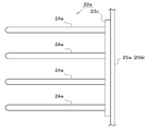
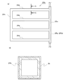
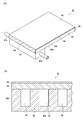
- FIG. 1 Schematic cross-sectional view taken along line AA in FIG. 1
- FIG. CC Schematic cross-sectional schematic view of FIG.
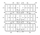
- Schematic plan view of the heat pipe in the solar cell panel heat sink / heat dissipating system of Embodiment 2 4 is a schematic cross-sectional view taken along line AA in FIG.
- FIG. 7 (a) Schematic perspective view showing a modified example of the heat dispersion member of the solar cell panel heat absorbing / dissipating system of Embodiment 2 (b) BB cross-sectional schematic view of FIG. 7 (a) Main part schematic plan view of heat pipe of solar cell panel heat absorption / dissipation system in Embodiment 3 (A) Schematic plan view of main parts of a heat pipe of the solar cell panel heat sink / heat dissipating system in Embodiment 4 (b) Schematic view of an end surface taken along line CC in FIG.
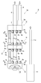
- FIG. 1 is a partially broken schematic side view showing a heat exchange unit according to Embodiment 1
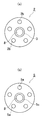
- FIG. 2 (a) is a schematic cross-sectional view taken along the line AA in FIG. 1
- FIG. 3 is a schematic cross-sectional view taken along the line BB of FIG. 1
- FIG. 3 is a schematic cross-sectional view taken along the line CC of FIG. In FIG.
- 1, 1 is a heat exchange unit according to the first embodiment
- 1a is a heat exchanger of the heat exchange unit 1 embedded in the ground or submerged in a liquid
- 2 is a heat exchange formed in a hollow ring shape.
- the upstream connecting body 2a of the vessel 1a is formed on the upstream surface side of the upstream connecting body 2 so that the heat medium flows in
- 2b is formed on the downstream surface side of the upstream connecting body 2 and the heat medium inlet section.
- 2a is a male screw part formed on the outer periphery of the heat medium outflow part 2b
- 3 is a through hole formed in the central part of the upstream connector 2 4
- a cap nut-like end connection portion that is detachably screwed to the male screw portion 6c of the portion 6b, 4c is disposed at the downstream end portion of the tube body 4a, and the heat medium inflow portion of the downstream connection body 5 to be described later
- a cap nut-shaped end connection portion 5, which is removably screwed to the male screw portion 5 b of 5 a and the male screw portion 6 c of the inflow side connection portion 6 a of the intermediate connection body 6, is formed in a hollow disc shape.
- a downstream connection body 5a of the heat exchanger 1a is formed on the upstream surface side of the downstream connection body 5, and a heat medium inflow portion into which the heat medium flowing out from the heat collection and radiating pipe 4 flows, 5b is an outer periphery of the heat medium inflow portion 5a.
- the male screw part 5c formed in the upstream side of the downstream connection body 5 is formed in the central part on the upstream side, and the heat medium outlet part 6 for collecting and discharging the heat medium flowing in from each heat medium inflow part 5a,
- the intermediate connection body 6a of the heat exchanger 1a formed in a hollow ring shape and disposed at the connecting portion of the tube body 4a is provided on the upstream surface side of the intermediate connection body 6.
- a plurality of inflow side connection portions 6b into which the heat medium flowing out from the upstream pipe body 4a flows, 6b is formed on the downstream surface side of the intermediate connection body 6, and the outflow from which the heat medium flowing in from the inflow side connection portion 6a flows out Side connection portion, 6c is a male screw portion formed on the outer periphery of the inflow side connection portion 6a and the outflow side connection portion 6b, 7 is an insertion hole formed in the central portion of the intermediate connection body 6, 8 is polypropylene, polybutene, Formed from a synthetic resin such as polyamide or a metal such as titanium, the end portion is connected to the heat medium outlet portion 5c of the downstream connection body 5, and the front end side and the middle in the longitudinal direction are the through hole 3 and the intermediate connection of the upstream connection body 2.
- the return pipe 9 of the heat exchanger 1a that circulates through the heat medium that is inserted through the insertion hole 7 of the body 6 and flows out from the heat medium outlet 5c is connected to the heat medium inlet 2a of the upstream connector 2.
- a heat medium supply pipe for supplying a heat medium to the heat exchanger 1a, 10 is a downstream connection body 5
- the fin 11 that stirs the heat medium flowing in from the plurality of heat medium inflow portions 5a is installed together with the heat exchanger 1a when the heat exchanger 1a is used by being submerged in a liquid such as ground water.
- a submersible pump 11a for pumping liquid to the upper side of the heat exchanger 1a and convection is a discharge pipe for discharging the liquid pumped by the submersible pump 11 to the upper side of the heat exchanger 1a.
- FIG. 1 for convenience of explanation, only one heat collecting / radiating tube 4 is shown, and the other heat collecting / radiating tube 4 is omitted. However, each heat medium outflow portion 2 b and downstream of the upstream connection body 2 are omitted.
- Each of the side connection bodies 5 is connected to each heat medium inflow portion 5a by a heat collecting / discharging pipe 4 connected to the pipe body 4a.
- the shape of the through hole 3 of the upstream connection body 2 and the insertion hole 7 of the intermediate connection body 6 is slightly larger than the outer shape of the return pipe 8. It was formed in a circular shape so that the return pipe 8 could be easily inserted.
- the return pipe 8 is inserted into the through hole 3 of the upstream connector 2 and the insertion hole 7 of the intermediate connector 6, rattling and displacement of the upstream connector 2 and intermediate connector 6 can be suppressed. .
- this makes it difficult for deformation of the heat-radiating / radiating pipe 4 and the return pipe 8 during construction such as burial, and is excellent in durability and workability.
- the through hole 3 of the upstream connection body 2 and the insertion hole 7 of the intermediate connection body 6 need only be able to pass through the return pipe 8 and do not necessarily have the same shape as or similar to the outer shape of the return pipe 8. .
- the intermediate connection body 6 is disposed at the connecting portion of the tube body 4a constituting the heat collection / radiation tube 4, thereby integrating the plurality of heat collection / radiation tubes 4 and improving the durability.
- the intermediate connection body 6 When the distance from the upstream connection body 2 to the downstream connection body 5 is short, the intermediate connection body 6 is not used and the upstream connection body 2 and the downstream connection body 5 are directly connected by the pipe body 4a. Also good. In addition, when connecting the pipe body 4a in several places, the intermediate connection body 6 does not need to be provided in all the connection parts of the pipe body 4a, and the arrangement
- the usage method of the heat exchange unit in Embodiment 1 comprised as mentioned above is demonstrated.
- the heat exchanging unit 1 in the first embodiment can be used by being buried in a hole dug in the ground or submerged in an existing well, underground water (in a well), hot spring water, or the like.
- a filler such as concrete, mortar, earth and sand, earth, and sand can be filled around the heat-radiating / radiating pipe 4 and the return pipe 8 of the heat exchanger 1a.
- the filler is not a hydraulic material such as concrete or mortar, but a granular filler such as silicon sand, earth, sand, silica sand, silicon waste, etc.
- the tip outlet of the return pipe 8 and the tip inlet of the heat medium supply pipe 9 are connected in a loop to a load device (not shown) such as a heat pump, a cooling / heating device, a snow melting device, etc.
- the heat medium supply pipe 9 supplies the upstream connection body 2 of the heat exchanger 1a.
- the heat medium flows from the upstream side to the downstream side of the heat collecting and radiating pipe 4 and exchanges heat with the ground via liquid such as surrounding earth and sand and groundwater.
- the heat medium that has undergone heat exchange gathers at the downstream connector 5 and is agitated by the fins 10 so that the temperature is uniformed, flows out from the heat medium outlet 5c, and is circulated to the load device by the return pipe 8.
- the heat exchanger 1a is set in the liquid, the liquid around the heat exchanger 1a is sequentially formed by setting the submersible pump 11 together and pumping the liquid above the heat exchanger 1a for convection.
- a loop-shaped heat medium pipe connected to the front end of the return pipe 8 and the front end of the heat medium supply pipe 9 is laid at the bottom of the tank buried in the ground, the snow is melted inside the tank in winter.
- As an embedded snowmelt box that can store water it is possible to effectively use snowmelt water.
- the water in the tank is cooled in summer, it can be used as a storehouse for food and drinks and is excellent in versatility.
- the heat exchanger includes an upstream connecting body having a heat medium inlet portion into which the heat medium flows and a plurality of heat medium outlet portions from which the heat medium flowing in from the heat medium inlet portion flows out, and one end portion A heat medium that flows into the upstream connection body by being provided with a plurality of heat-dissipating pipes that are detachably connected to the heat medium outflow part of the upstream connection body and send the heat medium flowing out of the heat medium outflow part.
- a heat exchanger a heat medium inflow portion into which a heat medium flowing out from each heat collecting / radiating tube flows, a heat medium outlet portion that collects and discharges the heat medium flowing in from each heat medium inflow portion,
- Each of the heat collection pipes is provided with a downstream connection body having a return pipe that circulates the heat medium that is connected to the heat medium outlet part of the downstream connection body and flows out of the heat medium outlet part.
- the heat medium that has passed through and collected heat can be collected and discharged from the return pipe, and can be quickly circulated in a short time, so heat exchange while passing through the return pipe can be kept low. Excellent in effective use of geothermal heat.
- not only exchanging the heat collection / radiation tube is easy and easy to maintain, but also select the length of the heat collection / radiation tube according to the temperature in the ground and the amount of heat required. It is easy to lengthen and is easy to design.
- each heat-dissipating tube is detachably connected to the upstream connector and the downstream connector of the heat exchanger, only the heat-dissipating tube that has failed such as damage can be replaced. Excellent maintenance and resource saving.
- the heat exchanger has a plurality of heat collecting / radiating tubes, the surface area of the heat collecting / radiating tubes can be increased, and the flow rate of the heat medium flowing through each of the heat collecting / radiating tubes can be reduced. Since it takes time to move through, it can sufficiently exchange heat with the ground, and excels in heat exchange efficiency and effective use of earth heat.
- the heat exchange amount between the return pipe and the ground is made smaller than the heat exchange amount between the heat collection and discharge pipe and the ground by making the total opening area of the heat collection and radiation pipe larger than the opening area of the return pipe. It can be suppressed and excels in heat exchange efficiency and certainty.
- the upstream connection body of the heat exchanger is formed in a hollow ring shape having a through hole in the center portion, and the return pipe of the heat exchanger is inserted through the through hole of the upstream connection body and penetrated.
- the upstream connector can be easily moved up and down along the longitudinal direction of the return tube.
- the downstream connection body can be shared, and it is excellent in versatility, mass productivity, and assembly workability.
- the return pipe of the heat exchanger is disposed at the center of the downstream connection body of the heat exchanger, and a plurality of heat collecting and radiating pipes of the heat exchanger are disposed at the outer periphery of the return pipe.
- Heat exchange between the heat radiating pipe and the ground is promoted, and heat exchange between the return pipe and the ground is kept low, and the heat medium is heated or cooled by effectively using the ground heat without waste. It excels in the efficiency of heat exchange and the effective use of earth heat.
- each heat collecting / radiating pipe of the heat exchanger is formed by connecting a plurality of pipes in series, the length of the heat collecting / radiating pipe can be freely adjusted, and assembly and disassembly workability Excellent design flexibility.
- An intermediate connection body disposed in a connecting portion of a plurality of pipe bodies includes an inflow side connection section in which a downstream end portion of the upstream pipe body is detachably connected, and an upstream side of the downstream pipe body.
- the intermediate connection body disposed in the connecting portion of the plurality of tube bodies has an insertion hole through which the return pipe is inserted, whereby the intermediate connection body is disposed at an arbitrary position in the longitudinal direction of the return pipe. It is excellent in design flexibility.
- the temperature of the heat medium is made uniform inside the downstream connection body by having fins that are arranged inside the downstream connection body of the heat exchanger and stir the heat medium flowing in from the plurality of heat medium inflow portions. Can be discharged from the outlet of the heat medium, and the temperature fluctuation of the circulating heat medium is small, and the stability of heating and cooling is excellent.
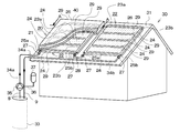
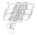
- FIG. 4 is a partially broken schematic perspective view showing a structure in which the solar cell panel heat absorbing / dissipating system of the second embodiment is introduced into the solar cell panel of the solar power generation system installed on the roof of the house
- FIG. 5 is the embodiment.
- FIG. 6 is a schematic plan view of a heat pipe in the solar cell panel heat absorbing / dissipating system of FIG. 2, and FIG.
- the same thing as Embodiment 1 attaches
- reference numeral 20 denotes a solar cell panel heat absorption / dissipation system according to the second embodiment (FIG. 4), which is disposed under the solar cell panel 40 of the solar power generation system mounted on the roof 31 of the house 30.
- Reference numeral 21 denotes a heat transfer plate (FIG. 4), which is formed of a metal plate such as copper having a high heat transfer rate, a far-infrared radiation plate, or the like and is disposed below the back cover (not shown) of the solar cell panel 40.
- Heat pipes 23a and 23b which are filled with an antifreeze working fluid that does not freeze up to around -30 ° C.
- the heat-source side heat source pipe Reference numeral 25b denotes a return side heat source pipe penetrating the header pipe 23b
- 26 denotes a connection pipe connecting between the feed side heat source pipe 25a and the return side heat source pipe 25b
- 27 denotes a feed side heat source of each heat pipe 22.
- a pipe 25a and a joint connected to the ends of the return side heat source pipe 25b, and 28, a joint 27 is provided between the adjacent return side heat source pipe 25b and the feed side heat source pipe 25a of the heat pipes 22 arranged in parallel.
- the heat exchanger 1a of the heat exchange unit 1 according to the first embodiment uses the connecting pipe 33, which is connected to the heat exchanger unit 1 of the first embodiment, using a borehole (ground well, heat collecting well) or a well excavated for heat collection in the ground.
- the bore holes (FIG. 4) and 34a to be buried or subsidized are covered with a heat insulating material (not shown) and connected between the return pipe 8 (see FIG. 1) of the heat exchanger 1a and the feed-side heat source pipe 25a.
- the pipe 34b is covered with a heat insulating material (not shown), and the return-side heat source pipe 25b and the heat exchanger 1 are covered.
- a return pipe connecting the heat medium supply pipe 9 (see FIG. 1), 35 is a pump (FIG. 4) disposed in the middle of the outgoing pipe 34a, and 36 is a branch pipe branched from the return pipe 34b (see FIG. 1). 4) and 37 are sealed expansion tanks (FIG. 4), the lower part of which is connected to the branch pipe 36, and a heat medium is accommodated on the branch pipe 36 side by a diaphragm or the like (not shown).
- a loop comprising the return pipe 8, the heat medium supply pipe 9, the flow side heat source pipe 25a, the return side heat source pipe 25b, the connection pipe 26, the connection pipe 28, the forward pipe 34a, the return pipe 34b, and the pump 35 of the heat exchanger 1a.
- the piping is filled with an antifreeze heat medium (antifreeze liquid) such as ethylene glycol, propylene glycol, potassium acetate aqueous solution, etc., and the volume change accompanying expansion / contraction of the heat medium is caused by the heat medium in the expansion tank 37. Buffer.
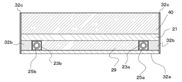
- 29 is a heat dispersion member that fills the space between the header pipes 23 a and the heat pipe branch pipes 24 of the heat pipe 22, and 32 a is formed in a plate shape with plywood, aluminum, etc.
- the base material on which the heat pipe 22 is placed on the upper surface, 32b is a fixing member for fixing the position of the heat pipe 22, and 32c is a frame that surrounds the solar cell panel 40 and the heat pipe 22 of the solar cell panel absorption / dissipation system 1 It is.
- the cross sections orthogonal to the longitudinal direction of the header pipes 23a and 23b and the heat pipe branch pipe 24 are formed in the same rectangular shape.
- the feed-side heat source pipe 25a and the return-side heat source pipe 25b are provided so as to extend along the longitudinal direction of the header pipes 23a and 23b. It is sealed with the outer peripheral wall of the heat source tube 25b.
- the heat of the heat medium flowing through the feed-side heat source pipe 25a and the return-side heat source pipe 25b passes through the wall surfaces of the feed-side heat source pipe 25a and the return-side heat source pipe 25b into the working fluid in the header pipes 23a and 23b. It is transmitted efficiently and heat loss can be suppressed.
- the flow-side heat source pipe 25a and the return-side heat source pipe 25b may be provided along the longitudinal direction of the header pipes 23a and 23b instead of penetrating the header pipes 23a and 23b. In this case, it is only necessary to arrange the flow-side heat source pipe 25a, the return-side heat source pipe 25b, and the header pipes 23a and 23b that are formed separately, which is excellent in mass productivity.
- the header pipes 23 a and 23 b of the heat pipe 22 are arranged in parallel to the gradient direction of the solar cell panel 40, and the heat pipe branch tube 24 is substantially orthogonal to the gradient direction of the solar cell panel 40. Is arranged.
- the heat pipe branch pipe 24 can be arranged so that the angle formed with the gradient direction of the solar cell panel 40 is in the range of 60 to 90 °, preferably 70 to 90 °.
- the snowmelt water melted by the heat of the heat pipe branch pipe 24 flows in a planar manner on the solar cell panel 40, so that only the snow around the heat pipe branch pipe 24 melts to form a snow cave. Therefore, it is possible to prevent the snow remaining on the solar cell panel 40 from being compacted and becoming unable to remove snow.
- FIG. 7A is a schematic perspective view showing a modification of the heat dispersion member of the solar cell panel heat absorption / dissipation system of the second embodiment
- FIG. 7B is a view taken along line BB in FIG. 7A. It is a cross-sectional schematic diagram.
- 38 is a heat dispersion member of a modification of the solar cell panel heat absorption / dissipation system of the second embodiment
- 38a is a thin-walled heat-dissipation member 38 made of a metal such as aluminum and having one surface open.
- the heat transfer section 38b is formed of inorganic fiber such as glass wool or rock wool, synthetic resin such as urethane foam or expanded polystyrene, fiber such as wood fiber, etc., and is fitted in the opening of the heat transfer section 38a. It is a heat insulating material.
- the heat dispersion member 38 can be arranged in place of the heat dispersion member 29 with the opening in which the heat insulating material 38b is fitted on the roof 31 side and the flat surface on the solar cell panel 40 side.
- the heat dissipating member 38 of the modified example can be reduced in weight because the heat transfer portion 38a is formed in a thin box shape, and the heat insulating material 19b is fitted in the opening, so that heat is radiated to the roof 31. The heat loss can be reduced.
- the usage method is demonstrated below.
- the heat medium in the heat exchanger 1a in the bore hole 33 is heated to about 13 ° C. by underground heat of about 15 to 17 ° C.
- the heated heat medium (antifreeze) in the heat exchanger 1a is driven by a pump 35 disposed in the outgoing pipe 34a, and sent from the outgoing pipe 34a to the heat pipe 22 installed in the solar cell panel 40. It is introduced into the side heat source pipe 25a.
- the heat medium introduced from the flow-side heat source pipe 25 a descends in the inclination direction of the solar cell panel 40 at the return-side heat source pipe 25 b facing through the connection pipe 26, and is adjacent through the joint 27 and the connection pipe 28.
- a heat exchanger in the bore hole 33 enters the heat-feed-side heat source pipe 25a of the heat pipe 22, goes down the return-side heat source pipe 25b facing through the connection pipe 26, passes through the return pipe 34b, and passes through the heat-medium supply pipe 9 It is recirculated to 1a and circulates in the loop piping.
- the heating medium is retained by heating one of the header pipes 23a with the heat medium first.
- the transmitted heat is transferred to the working fluid in the header pipe 23a, and the heated working fluid evaporates toward the heat pipe branch pipe 24 and the other header pipe 23b.
- the working fluid vapor diffuses and condenses in the heat pipe branch pipe 24 to release condensation heat, and radiates heat to the heat dispersion member 29 and the back cover of the solar cell panel 40 through the pipe wall of the heat pipe branch pipe 24.
- the heat radiated to the back cover is transferred to the filler and the cell, and then transferred to the front cover.
- the heat medium that has flowed through the flow-side heat source pipe 25a of one header pipe 23a then enters the return-side heat source pipe 25b of the other header pipe 23b, and evaporates the working fluid in the other header pipe 23b.
- the working fluid condensed by heat exchange is returned to the header tube 23a.
- the snow melting In the snow melting, first, the snow accumulated on the solar cell panel 40 on the heat pipe branch pipe 24 and the header pipes 23a and 23b having a high temperature is melted, and the snow melting water flows on the surface of the solar cell panel 40 along the roof gradient. Therefore, the lower surface of the snow surrounded by the heat pipe branch pipe 24 and the header pipes 23a and 23b is melted by the melted water, and the entire snow accumulated on the solar cell panel 40 can be removed eventually.
- the heat of the solar cell panel 40 is transferred to the heat transfer plate 21 via the back cover, Next, it is transmitted to the heat dispersion member 29 and the heat pipe branch pipe 24.
- the working fluid in the heat pipe branch pipe 24 absorbs the heat transmitted to the heat pipe branch pipe 24 and evaporates, and evaporates toward both header pipes 23a and 23b by capillary action. As a result, the heat retained by the working fluid is applied to both header tubes 23a and 23b.
- the heat in the header pipes 23a and 23b is radiated to the flow-side heat source pipe 25a and the return-side heat source pipe 25b.
- the working fluid condensed in the header pipes 23a and 23b flows into the heat pipe branch pipe 24 by a capillary phenomenon, takes the heat of the solar cell panel 40 again, and evaporates toward the header pipes 23a and 23b.
- the heat of the header pipes 23a and 23b is carried into the ground by the heat medium passing through the flow-side heat source pipe 25a and the return-side heat source pipe 25b, and becomes a low-temperature heat medium again through the heat exchanger 1a. While being sent to the pipes 23a and 23b, heat is stored in the ground around the bore hole 33.
- the heat dispersion member 29 is separately installed on the base material 32a.
- the base material 32a and the heat dispersion member 29 are integrated with a metal such as aluminum, synthetic resin, concrete, or the like.
- the header pipes 23a and 23b and the heat pipe branch pipe 24 of the heat pipe 22 are fitted into the integrally formed depression. Thereby, the effect
- a jacket is provided in the outgoing pipe 34a on the downstream side of the pump 35, and the waste water is introduced into the jacket, and the exhaust heat such as the waste water in the jacket is exchanged with the antifreeze liquid through the pipe wall of the outgoing pipe 34a.
- the antifreeze can be heated by the waste heat of the waste water.
- the temperature of the antifreeze liquid can be temporarily raised, and the snow on the solar cell panel 40 can be melted by exhaust heat, so that the exhaust heat can be effectively used.
- the heat pipe includes a header pipe, a plurality of heat pipe branch pipes branched from the header pipe, and a working fluid sealed in the header pipe and the heat pipe branch pipe.
- the entire solar cell panel can be widely covered with the plurality of heat pipe branch pipes.
- Heat can be absorbed and dissipated reliably between the heat pipe branch pipes, and the header pipe can be shortened.
- the length of the heat source pipe attached to or penetrating the header pipe can be shortened, the path of the heat source pipe disposed in the solar cell panel is shortened, and the pipe friction resistance is reduced.
- the output of the pump to be sent can be reduced and the size can be reduced, energy saving and space saving are excellent, and the power consumption of the pump is extremely low. Cost can also be reduced, and the efficiency and stability of solar power generation can be improved.
- the generated heat is applied to the lower part of the solar cell panel even if the solar cell panel is irradiated with strong sunlight for a long time.
- Heat is transferred to the installed heat pipe, but heat is transferred from the heat pipe branch pipe to the header pipe so rapidly that there is no temperature difference between the heat pipe branch pipe and the header pipe, and further, heat is transferred to the heat medium in the heat source pipe.
- the entire solar cell panel is uniformed at a substantially constant temperature without being overheated, and a reduction in power generation efficiency due to thermal runaway can be prevented.
- a heat source pipe is attached to or penetrates a header pipe of a heat pipe disposed below or above the back cover of the solar cell panel, and the heat exchanger and the heat source pipe of the heat exchange unit are connected to form a heat medium.
- the heat of the heat medium in the heat source pipe is transferred to the header pipe even if snow is accumulated on the solar panel, and the heat of the header pipe is so rapid that there is no temperature difference between the heat pipe branch pipe and the header pipe. Since it is transmitted to the heat pipe branch pipe, the entire solar cell panel can be warmed almost uniformly throughout the heat pipe to melt the snow accumulated on the solar cell panel, and the incident of sunlight is blocked by the snow The reliability of solar power generation and the efficiency of power generation can be improved.
- the heat pipe placed under or above the back cover of the solar cell panel can eliminate the temperature variation of the entire solar cell panel, so that the temperature state of the solar cell panel can be correctly grasped and the temperature is adjusted. It is easy to set the optimum temperature, and the stability of power supply can be improved.
- the heat exchanger of the heat exchange unit connected to the heat source pipe attached to or penetrating the header pipe of the heat pipe is buried in the ground or submerged in the ground water and exchanges heat with the ground water. As it is done, surplus heat applied to the solar panel in the summer is transferred to the heat medium in the heat source pipe and stored as geothermal heat, and in the winter, the geothermal can be reused for melting snow on the solar panel.
- the power generation efficiency of the solar cell panel can be maximized with the minimum energy consumption required to drive the pump that circulates the heat medium.
- the heat pipe can be installed directly on the upper part of the back cover (lower part of the cell) inside the solar cell panel, heat exchange with the cell is possible, and heat loss and temperature spots are greatly reduced during heat absorption and release.
- the power generation efficiency of the entire solar cell panel can be stabilized, and the power generation efficiency over time can also be stabilized.
- the heat pipe is arranged on the upper part of the back cover, the cell temperature can be adjusted with the minimum necessary cooling energy, and the energy consumed for the temperature adjustment of the solar panel can be significantly reduced.
- the power generation efficiency can be maximized, and the energy saving and power generation efficiency can be improved.
- FIG. 8 is a schematic plan view of a main part of a heat pipe of the solar cell panel heat sink / heat dissipating system in the third embodiment.
- symbol is attached
- the heat pipe 22a of the solar panel absorption and radiating system in the third embodiment is different from the second embodiment in that only one end side of the plurality of heat pipe branch pipes 24a communicates with the header pipe 23c.
- the flow-side heat source pipe 25a or the return-side heat source pipe 25b is formed to have substantially the same thickness (height) as the header pipe 23c and is attached in the longitudinal direction of the header pipe 23.
- header tube 23c is arranged along the gradient direction of solar cell panel 40
- heat pipe branch tube 24a is the solar cell panel. Arranged so as to be substantially orthogonal to the gradient direction of 40, it is constructed in the same manner as in the second embodiment.
- the following operation is obtained in addition to the same operation as in the second embodiment.
- FIG. 9A is a schematic plan view of the main part of the heat pipe of the solar cell panel heat absorbing / dissipating system in the fourth embodiment
- FIG. 9B is a schematic end view taken along the line CC of FIG. 9A. It is.
- the thing similar to Embodiment 2 or 3 attaches
- the heat pipe 22b of the solar cell panel heat absorbing / dissipating system in the fourth embodiment is different from the second embodiment in that only one end side of the plurality of heat pipe branch pipes 24b communicates with the header pipe 23c.
- the other end of the plurality of heat pipe branch pipes 24b are connected by a pressure equalizing pipe 24c. Further, as shown in FIG. 9B, the surface of the heat pipe branch pipe 24b has a heat conductive layer 39 coated with silicon ore powder and fine powder.
- the header pipe 23c is arranged along the gradient direction of the solar battery panel 40, and the heat pipe branch pipe 24b is the solar battery panel. It is arranged so as to be substantially orthogonal to the 40 gradient directions and is constructed in the same manner as in the first embodiment.
- the following actions are obtained in addition to the same actions as in the second embodiment.
- FIG. 10 is a schematic plan view of a main part of a heat pipe of the solar cell panel heat sink / heat dissipating system in the fifth embodiment. Components similar to those in Embodiments 2 to 4 are denoted by the same reference numerals and description thereof is omitted.
- the heat pipe 22c of the solar cell panel heat sink / heat dissipating system in the fifth embodiment is different from that in the second embodiment in that a plurality of heat pipe branch pipes 24d communicate with each other around the single header pipe 23c. It is a point.
- the surface of the heat pipe branch pipe 24d may be coated with silicon ore powder or fine powder to form the heat conductive layer 39.
- the header pipe 23c is arranged along the gradient direction of the solar battery panel 40, and the heat pipe branch pipe 24d is the solar battery panel. It is arranged so as to be substantially orthogonal to the 40 gradient directions and is constructed in the same manner as in the first embodiment.
- the following actions are obtained in addition to the same actions as in the second embodiment. (1) Since multiple heat pipe branch pipes are spread out from side to side centering on the header pipe, heat can be exchanged effectively with almost the entire surface of the solar cell panel with a simple structure. Excellent.
- FIG. 11 is a partially broken schematic perspective view showing a structure in which the solar cell panel heat absorbing / dissipating system of the sixth embodiment is introduced to the solar cell panel of the solar tracking type solar power generation system, and FIG. It is a model top view of the heat pipe in the solar cell panel absorption-and-dissipation system of this. Components similar to those in the second to fifth embodiments are denoted by the same reference numerals and description thereof is omitted.
- the solar cell panel heat absorbing / dissipating system 20a in the sixth embodiment is different from the second embodiment in the number, arrangement and heat medium path of the heat pipes 22d, and the basic operation is performed. This is the same as the second embodiment. Moreover, since the usage method is the same as that of Embodiment 2, description is abbreviate
- the solar tracking type photovoltaic power generation system adjusts the angle between the solar cell panel 40 and the ground surface so that it can rotate around the two axes orthogonal to each other, thereby controlling the movement of the sun. It is possible to track and always obtain the maximum amount of incident light.
- the solar cell panel 40 can be moved in various directions by forming the forward tube 34a and the return tube 34b located at the movable part with an elastic material such as resin or rubber, or with a deformable flexible tube. Become.
- the same operation as in the second embodiment can be obtained.
- FIG. 13 is a schematic plan view of a main part of a heat pipe of the solar cell panel heat absorbing / dissipating system of the seventh embodiment. Components similar to those in the second to sixth embodiments are denoted by the same reference numerals and description thereof is omitted.
- the heat pipe 22e of the solar cell panel heat sink / heat dissipating system in the seventh embodiment is different from that in the sixth embodiment in that the flow side heat source pipe 25a and the return side heat source pipe 25b of each heat pipe 22e are respectively.
- the basic operation is the same as that of the sixth embodiment in that it is directly connected to the outgoing pipe 34a and the return pipe 34b. Further, since the method of use is the same as that of the sixth embodiment, description thereof is omitted.
- the following operation is obtained in addition to the same operation as in the second embodiment.
- FIG. 14 (a) is a schematic perspective view of a heat pipe plate of the solar panel absorption / dissipation system of Embodiment 8
- FIG. 14 (b) is a view of the heat pipe plate of the solar panel absorption / dissipation system of Embodiment 8. It is a principal part cross-section enlarged schematic diagram. Components similar to those in the second to thirteenth embodiments are given the same reference numerals and description thereof is omitted.
- 41 is a heat pipe plate of the solar cell panel heat absorbing / dissipating system of Embodiment 8
- 42 is a plurality of grooves 43 (FIG.
- the substrate portion of the heat pipe plate 41, 42 a is the back surface of the substrate portion 42, 42 b is the side end portion in the width direction (left and right) of the substrate portion 42, and 44 is a flat plate made of the same material as the substrate portion 42.
- the cover part 45 of the heat pipe plate 41 formed in a shape and covered on the surface of the groove part 43 or the substrate part 42 contains a silicon particle as a heat conductive material, and is a coating film applied on the outer surface of the cover part 44
- the heat conduction layer of the heat pipe plate 41 formed by the above, 46 is a closing portion that closes both ends of the opening 43 in the longitudinal direction of the groove portion 43 of the substrate portion 42 by soldering, and 47 is one end portion of the heat pipe plate 41 in the longitudinal direction.
- Heat attached to The pipe 47a is connected to the forward pipe 34a (see FIG. 4) and is an inlet pipe of the heat source pipe 47 into which the refrigerant flows.
- 47b is connected to the return pipe 34b (see FIG.
- each groove part 43 of the heat pipe plate 41 is depressurized to the same degree of vacuum as the heat pipe 22 and the like of the second embodiment, and the working fluid is enclosed.
- the substrate portion 42 and the lid portion 44 can be fixed and integrated by a method such as pressure bonding, welding, adhesion, and diffusion bonding.
- the width and height of the groove 43 were selected within a range where extrusion, drawing, or pressing was possible depending on the thickness of the substrate 42.
- the groove 43 is formed in a vertically long flat shape to facilitate the capillary action, so that the working fluid can be moved in a short time, and the efficiency of heat transfer is improved. be able to.
- the heat conductive layer 45 contains 0.01 to 45 parts by weight of silicon particles as a heat conductive material with respect to 100 parts by weight of a resin-based paint using a synthetic resin such as polyurethane resin, epoxy resin, or silicon resin. A paint was applied to the surface of the lid 4 to form. As the content of silicon particles is less than 0.01 parts by weight with respect to 100 parts by weight of the paint, the heat dissipation and endothermic properties tend to decrease, and as the amount exceeds 45 parts by weight, the heat conductive layer 5 is used. This is because it has been found that the adhesion, wear resistance, and durability of the glass tend to be lowered.
- the heat conductive layer 5 when forming the heat conductive layer 5 with a coating film, you may use the oil-based coating material of drying oil or semi-drying oil other than resin coating material. Silicon grains having a purity of 75% or more were used. This is because it has been found that when the purity of the silicon particles is lower than 75%, the thermal conductivity of the silicon particles is lowered and it is difficult to obtain sufficient heat dissipation and heat absorption.
- produces in the manufacturing process of a semiconductor element material and the crushing waste of a silicon wafer can be used not only as what grind
- silicon particles that have been conventionally disposed of as waste or used as road aggregates can be effectively reused, resulting in excellent productivity and resource saving.
- silicon particles are used as the heat conductive material, but the present invention is not limited to this, and carbon materials such as artificial graphite materials made from petroleum coke and the like, carbon fibers, barley stones, Amaterasu Far-infrared emitters such as natural minerals such as stone and zeolite, alumina, silica, zirconia, titania, magnesia and their composite oxides, ceramics such as silicon nitride and silicon carbide, carbides, and silicon ores can be used. These may be used alone or in combination.
- carbon materials such as artificial graphite materials made from petroleum coke and the like, carbon fibers, barley stones, Amaterasu Far-infrared emitters such as natural minerals such as stone and zeolite, alumina, silica, zirconia, titania, magnesia and their composite oxides, ceramics such as silicon nitride and silicon carbide, carbides, and silicon ores can be used. These may be used alone or in combination.
- the particle size of the silicon particles was 1 nm to 2 mm. As the particle size of the thermally conductive material becomes smaller than 1 nm, the workability and the handleability tend to be lowered, and as it becomes larger than 2 mm, the adhesion, wear resistance and durability tend to be lowered. It was because it was found that there was. In addition, by widening the particle size distribution of the heat conductive material contained in the heat conductive layer, the heat conductive material can be laminated at a high density, and the heat dissipation and heat absorption uniformity are excellent.
- the heat conductive layer 45 is formed on the surface of the lid portion 44, but the heat conductive layer 45 may be formed on the back surface 42 a of the substrate portion 42. This is because the surface on which the heat conductive layer 45 is formed becomes a heat radiating surface or a heat absorbing surface. Note that the heat conductivity can be improved by forming the heat conductive layer 45 on the inner peripheral surface of the groove 43.
- the heat conductive layer 45 is formed of a coating film, but the method of forming the heat conductive layer 45 is not limited to this, and the substrate portion 42 and the lid portion 44 that form the heat conductive layer 45 are not limited thereto. It is only necessary that the surface and the heat conductive layer 45 have adhesiveness. According to the type and particle size of the heat conductive material, the surface can be appropriately selected from various methods such as plating, adhesion, and thermal spraying. Can be used. Moreover, you may laminate and form what was previously made into a sheet. The thickness of the heat conductive layer 45 can be selected in the range of 0.1 ⁇ m to 3 mm according to the type of heat conductive material and the method of forming the heat conductive layer 45.
- the thickness of the heat conductive layer 45 becomes thinner than 0.1 ⁇ m, it becomes difficult to handle and form, and the durability tends to be lowered. This is because it has been found that the heat transferability between the lid portion 44 and the heat conductive layer 45 tends to decrease.
- the entire cross-sectional shape of the groove 43 is formed in a vertically long substantially square shape.
- the present invention is not limited to this. It can be formed in the shape of Moreover, when forming the groove part 43 by extrusion or drawing, it can be set as the shape which has many unevenness
- the pattern of the groove part 43 is not limited to this Embodiment, You may form in the shape of one meandering loop.
- the difference between the heat pipe plate 41 of the solar cell panel heat absorption / dissipation system in the eighth embodiment and the heat pipe 22b of the solar cell panel heat absorption / radiation system in the fourth embodiment is that the shape is formed in a flat plate shape.
- the basic operation is the same as in the fourth embodiment.
- the usage method is the same as that of Embodiment 4, description is abbreviate
- the solar cell panel heat absorbing / dissipating system in Embodiment 4 configured as described above, the following operation is obtained.
- the temperature can be kept constant over time in a state where there is no spot in the temperature distribution, and the efficiency and stability of solar power generation can be improved.
- the heat pipe plate placed at the bottom or top of the back cover of the solar cell panel can eliminate the temperature variation of the entire solar cell panel, so that the temperature state of the solar cell panel can be correctly grasped and the temperature adjusted. It is easy to set the optimum temperature at the time, and the stability of power supply can be improved.
- the geothermal heat can be reused for melting snow on solar panels, and the pump that circulates the heat medium is driven throughout the year. Only with minimal energy consumption, the power generation efficiency of the solar panel can be maximized.
- the heat pipe plate can be placed directly on the upper part of the back cover inside the solar cell panel (lower part of the cell), it can exchange heat directly with the cell, eliminating heat loss and temperature spots when absorbing and radiating heat. The power generation efficiency of the entire solar cell panel can be stabilized, and the power generation efficiency over time can also be stabilized.
- the heat pipe plate is arranged on the upper part of the back cover, the temperature of the cell can be adjusted with the minimum required cooling energy, and the energy consumed for temperature adjustment of the solar cell panel is remarkably reduced.
- the present invention has a simple configuration, can simplify the shape, can be easily assembled, disassembled and partially replaced, and is not only excellent in mass production, maintenance, storage, and transportability, but also has a longer length.
Landscapes
- Engineering & Computer Science (AREA)
- General Engineering & Computer Science (AREA)
- Mechanical Engineering (AREA)
- Life Sciences & Earth Sciences (AREA)
- Chemical & Material Sciences (AREA)
- Thermal Sciences (AREA)
- Physics & Mathematics (AREA)
- Sustainable Development (AREA)
- Sustainable Energy (AREA)
- Combustion & Propulsion (AREA)
- Dispersion Chemistry (AREA)
- General Life Sciences & Earth Sciences (AREA)
- Road Paving Structures (AREA)
Abstract
L'invention concerne une unité d'échange de chaleur comme quoi une forme simple peut être obtenue par une structure simple, comme quoi l'assemblage, le démontage, et les échanges partiels sont faciles, comme quoi d'excellentes opérations de productivité, de maintenabilité, d'aptitude au stockage et de portabilité de masse peuvent être obtenues, comme quoi la longueur peut être facilement étendue, comme quoi une excellente qualité de flexibilité et de versatilité de conception peut être obtenue, comme quoi la chaleur souterraine peut être utilisée de manière efficace, et comme quoi un excellent rendement d'échange thermique peut être obtenu. Un échangeur de chaleur comporte : (a) un corps de raccordement en amont comprenant une partie d'entrée de fluide caloporteur et une pluralité de parties de sortie de fluide caloporteur; (b) une pluralité de tuyaux de captage/rayonnement de chaleur raccordés de manière détachable aux parties de sorties de fluide caloporteur pour envoyer un fluide caloporteur qui s'écoule hors des parties de sortie de fluide caloporteur; (c) un corps de raccordement en aval comprenant une partie d'admission de fluide caloporteur dans lequel le fluide caloporteur s'écoulant hors des tuyaux respectifs de captage/rayonnement de chaleur s'écoule, et une partie de sortie de fluide caloporteur permettant de décharger de manière collective le fluide caloporteur s'écoulant en provenance des parties respectives d'admission de fluide caloporteur; et (d) un tuyau de retour ayant une partie terminale raccordée à la partie de sortie de fluide caloporteur du corps de raccordement en aval à des fins de circulation du fluide caloporteur s'écoulant hors de la partie de sortie de fluide caloporteur.
Applications Claiming Priority (2)
| Application Number | Priority Date | Filing Date | Title |
|---|---|---|---|
| JP2011-166604 | 2011-07-29 | ||
| JP2011166604 | 2011-07-29 |
Publications (1)
| Publication Number | Publication Date |
|---|---|
| WO2013018660A1 true WO2013018660A1 (fr) | 2013-02-07 |
Family
ID=47629185
Family Applications (1)
| Application Number | Title | Priority Date | Filing Date |
|---|---|---|---|
| PCT/JP2012/069031 Ceased WO2013018660A1 (fr) | 2011-07-29 | 2012-07-26 | Unité d'échange de chaleur, et système d'absorption/de rayonnement de chaleur utilisant celle-ci pour un panneau de batteries solaires |
Country Status (1)
| Country | Link |
|---|---|
| WO (1) | WO2013018660A1 (fr) |
Cited By (2)
| Publication number | Priority date | Publication date | Assignee | Title |
|---|---|---|---|---|
| US11924145B2 (en) | 2019-05-21 | 2024-03-05 | Qualcomm Incorporated | Multiple power references for high rank transmissions |
| CN118338626A (zh) * | 2024-05-17 | 2024-07-12 | 中国长江三峡集团有限公司 | 一种数据中心制冷系统 |
Citations (7)
| Publication number | Priority date | Publication date | Assignee | Title |
|---|---|---|---|---|
| JPH0332604U (fr) * | 1989-04-04 | 1991-03-29 | ||
| JPH11222803A (ja) * | 1997-11-25 | 1999-08-17 | Nozawa Service Center:Kk | 融雪システム |
| JP2003302109A (ja) * | 2002-04-08 | 2003-10-24 | Ariga Sakusen Kogyo:Kk | 地中熱交換器 |
| JP2005257140A (ja) * | 2004-03-10 | 2005-09-22 | Matsushita Electric Ind Co Ltd | ソーラーヒートポンプシステム、およびその運転方法 |
| WO2007091680A1 (fr) * | 2006-02-10 | 2007-08-16 | Just Thokai Co., Ltd. | Structure et dispositif servant à faire fondre la neige sur un toit et un appentis |
| JP2009041231A (ja) * | 2007-08-07 | 2009-02-26 | Fairy Angel Inc | 埋設型熱交換器及びその製造方法 |
| JP2009127982A (ja) * | 2007-11-27 | 2009-06-11 | Sekisui Chem Co Ltd | 地熱利用システム |
-
2012
- 2012-07-26 WO PCT/JP2012/069031 patent/WO2013018660A1/fr not_active Ceased
Patent Citations (7)
| Publication number | Priority date | Publication date | Assignee | Title |
|---|---|---|---|---|
| JPH0332604U (fr) * | 1989-04-04 | 1991-03-29 | ||
| JPH11222803A (ja) * | 1997-11-25 | 1999-08-17 | Nozawa Service Center:Kk | 融雪システム |
| JP2003302109A (ja) * | 2002-04-08 | 2003-10-24 | Ariga Sakusen Kogyo:Kk | 地中熱交換器 |
| JP2005257140A (ja) * | 2004-03-10 | 2005-09-22 | Matsushita Electric Ind Co Ltd | ソーラーヒートポンプシステム、およびその運転方法 |
| WO2007091680A1 (fr) * | 2006-02-10 | 2007-08-16 | Just Thokai Co., Ltd. | Structure et dispositif servant à faire fondre la neige sur un toit et un appentis |
| JP2009041231A (ja) * | 2007-08-07 | 2009-02-26 | Fairy Angel Inc | 埋設型熱交換器及びその製造方法 |
| JP2009127982A (ja) * | 2007-11-27 | 2009-06-11 | Sekisui Chem Co Ltd | 地熱利用システム |
Cited By (2)
| Publication number | Priority date | Publication date | Assignee | Title |
|---|---|---|---|---|
| US11924145B2 (en) | 2019-05-21 | 2024-03-05 | Qualcomm Incorporated | Multiple power references for high rank transmissions |
| CN118338626A (zh) * | 2024-05-17 | 2024-07-12 | 中国长江三峡集团有限公司 | 一种数据中心制冷系统 |
Similar Documents
| Publication | Publication Date | Title |
|---|---|---|
| Ghazy et al. | Cooling technologies for enhancing photovoltaic–thermal (PVT) performance: a state of the art | |
| JP4214881B2 (ja) | 気泡ポンプ型熱輸送機器 | |
| Rashidi et al. | A review on potentials of coupling PCM storage modules to heat pipes and heat pumps: S. Rashidi et al. | |
| JP2011077379A (ja) | 太陽電池パネル吸放熱システム | |
| JP6524571B2 (ja) | 熱交換装置の制御方法及び熱交換装置並びに水冷式ヒートポンプ冷暖房装置・水冷式ヒートポンプ装置 | |
| KR101368362B1 (ko) | 지열을 이용한 냉난방 시스템 | |
| US9027634B2 (en) | Underground thermal battery storage system | |
| JP2013181676A (ja) | 冷暖房システム及び冷暖房方法 | |
| US20150292770A1 (en) | Solar thermal collector system and method for pitched roof constructions | |
| JP2014025688A (ja) | 熱交換ユニット | |
| US20090211568A1 (en) | Thermal Storage System | |
| JP4324223B2 (ja) | 屋根の融雪構造及び融雪装置 | |
| JP4428453B2 (ja) | 気泡ポンプ型熱輸送機器 | |
| US11555658B2 (en) | Methods and systems to convert passive cooling to active cooling | |
| JP2008249260A (ja) | 熱交換装置 | |
| CN116324297A (zh) | 用于热模块的基槽、包括此基槽的热模块、用于提取热能的系统以及用基槽从阳光中提取热能的用途 | |
| JP2012063062A (ja) | 地下蓄熱層を有する冷暖房システム及び同冷暖房システムに用いる地下蓄熱層の構造 | |
| CN102080886A (zh) | 利用土壤的储能装置 | |
| CN202188666U (zh) | 太阳能集热器 | |
| WO2016124338A1 (fr) | Agencement de modules solaires et procédé de rattrapage d'un élément de module solaire | |
| WO2018225753A1 (fr) | Procédé de commande de dispositif d'échange de chaleur, dispositif d'échange de chaleur et dispositif de pompe à chaleur refroidi par l'eau | |
| KR20080027180A (ko) | 지하수의 지상유출 방지기능을 갖는 지열공 연통구조 | |
| JP4702556B2 (ja) | 太陽熱の地中内熱備蓄方法と装置 | |
| KR101110690B1 (ko) | 내부에 순환회로를 가진 히트파이프를 이용한 대양열 집 열기. | |
| US12455120B1 (en) | Heating and cooling of buildings using underground heat storage |
Legal Events
| Date | Code | Title | Description |
|---|---|---|---|
| 121 | Ep: the epo has been informed by wipo that ep was designated in this application |
Ref document number: 12820351 Country of ref document: EP Kind code of ref document: A1 |
|
| NENP | Non-entry into the national phase |
Ref country code: DE |
|
| 32PN | Ep: public notification in the ep bulletin as address of the adressee cannot be established |
Free format text: NOTING OF LOSS OF RIGHTS PURSUANT TO RULE 112(1) EPC (EPO FORM 1205N DATED 12-06-2014) |
|
| NENP | Non-entry into the national phase |
Ref country code: JP |
|
| 122 | Ep: pct application non-entry in european phase |
Ref document number: 12820351 Country of ref document: EP Kind code of ref document: A1 |