WO2013024723A1 - Organe de coupe de fibre optique - Google Patents
Organe de coupe de fibre optique Download PDFInfo
- Publication number
- WO2013024723A1 WO2013024723A1 PCT/JP2012/069898 JP2012069898W WO2013024723A1 WO 2013024723 A1 WO2013024723 A1 WO 2013024723A1 JP 2012069898 W JP2012069898 W JP 2012069898W WO 2013024723 A1 WO2013024723 A1 WO 2013024723A1
- Authority
- WO
- WIPO (PCT)
- Prior art keywords
- optical fiber
- cutter
- slider
- holder
- display mechanism
- Prior art date
- Legal status (The legal status is an assumption and is not a legal conclusion. Google has not performed a legal analysis and makes no representation as to the accuracy of the status listed.)
- Ceased
Links
Images




Classifications
-
- G—PHYSICS
- G02—OPTICS
- G02B—OPTICAL ELEMENTS, SYSTEMS OR APPARATUS
- G02B6/00—Light guides; Structural details of arrangements comprising light guides and other optical elements, e.g. couplings
- G02B6/24—Coupling light guides
- G02B6/25—Preparing the ends of light guides for coupling, e.g. cutting
-
- B—PERFORMING OPERATIONS; TRANSPORTING
- B26—HAND CUTTING TOOLS; CUTTING; SEVERING
- B26D—CUTTING; DETAILS COMMON TO MACHINES FOR PERFORATING, PUNCHING, CUTTING-OUT, STAMPING-OUT OR SEVERING
- B26D7/00—Details of apparatus for cutting, cutting-out, stamping-out, punching, perforating, or severing by means other than cutting
- B26D7/27—Means for performing other operations combined with cutting
- B26D7/28—Means for performing other operations combined with cutting for counting the number of cuts or measuring cut lenghts
-
- Y—GENERAL TAGGING OF NEW TECHNOLOGICAL DEVELOPMENTS; GENERAL TAGGING OF CROSS-SECTIONAL TECHNOLOGIES SPANNING OVER SEVERAL SECTIONS OF THE IPC; TECHNICAL SUBJECTS COVERED BY FORMER USPC CROSS-REFERENCE ART COLLECTIONS [XRACs] AND DIGESTS
- Y10—TECHNICAL SUBJECTS COVERED BY FORMER USPC
- Y10S—TECHNICAL SUBJECTS COVERED BY FORMER USPC CROSS-REFERENCE ART COLLECTIONS [XRACs] AND DIGESTS
- Y10S83/00—Cutting
- Y10S83/913—Filament to staple fiber cutting
-
- Y—GENERAL TAGGING OF NEW TECHNOLOGICAL DEVELOPMENTS; GENERAL TAGGING OF CROSS-SECTIONAL TECHNOLOGIES SPANNING OVER SEVERAL SECTIONS OF THE IPC; TECHNICAL SUBJECTS COVERED BY FORMER USPC CROSS-REFERENCE ART COLLECTIONS [XRACs] AND DIGESTS
- Y10—TECHNICAL SUBJECTS COVERED BY FORMER USPC
- Y10T—TECHNICAL SUBJECTS COVERED BY FORMER US CLASSIFICATION
- Y10T225/00—Severing by tearing or breaking
- Y10T225/30—Breaking or tearing apparatus
- Y10T225/307—Combined with preliminary weakener or with nonbreaking cutter
- Y10T225/321—Preliminary weakener
-
- Y—GENERAL TAGGING OF NEW TECHNOLOGICAL DEVELOPMENTS; GENERAL TAGGING OF CROSS-SECTIONAL TECHNOLOGIES SPANNING OVER SEVERAL SECTIONS OF THE IPC; TECHNICAL SUBJECTS COVERED BY FORMER USPC CROSS-REFERENCE ART COLLECTIONS [XRACs] AND DIGESTS
- Y10—TECHNICAL SUBJECTS COVERED BY FORMER USPC
- Y10T—TECHNICAL SUBJECTS COVERED BY FORMER US CLASSIFICATION
- Y10T83/00—Cutting
- Y10T83/525—Operation controlled by detector means responsive to work
- Y10T83/541—Actuation of tool controlled in response to work-sensing means
- Y10T83/544—With trip-switch in work-sensing mechanism
Definitions
- the optical fiber cutter has an initial damage to the optical fiber by pressing the optical fiber on the leaf spring with a fiber clamp, then lowering the cover and pushing the blade into the optical fiber.
- There is also one that causes the counter to display the cumulative number of times the blade has been used for example, Patent Document 2).
- JP 2008-203815 A Japanese Utility Model Publication No. 2-62405
- the present invention relates to an optical fiber cutter for cutting an optical fiber, a cutter base having a holder guide portion for positioning a fiber holder that holds the optical fiber, and a blade member that is movably attached to the cutter base and scratches the optical fiber.
- the slider has a slider, is attached to the cutter base so as to be openable and closable, and a cutter lid that moves the slider so as to return to the initial position by closing the cutter base, and the number of times the slider returns to the initial position.
- a control means for mechanically controlling the count display mechanism so that the count operation by the count display mechanism is enabled only when the fiber holder is set on the holder guide. It is characterized by comprising.
- the fiber holder can be In a state where the slider is not set, even if the slider is moved back to the initial position, the count display mechanism does not count the number of times the slider returns to the initial position. Thereby, the number of cuts of the optical fiber can be accurately counted and displayed by the count display mechanism.
- the control means is provided in the holder guide part, and the claw member that is pushed when the fiber holder is set in the holder guide part and the count display mechanism only when the slider returns to the initial position while the claw member is pushed. It can be configured to have a rotation driving means for rotating by an angle corresponding to one count. In this case, when the fiber holder is set on the holder guide portion, the claw member is pushed, and when the slider is returned to the initial position in this state, the count display mechanism rotates by an angle corresponding to one count. On the other hand, when the fiber holder is not set in the holder guide portion, the claw member is not pushed, so that even if the slider is returned to the initial position, the count display mechanism does not rotate by an angle corresponding to one count. Thereby, only when the fiber holder is set in the holder guide portion, the counting operation by the count display mechanism is validated.
- the engaging portion has an inclined surface that is inclined so as to rotate the rotating member as the protrusion moves toward the initial position in a state where the claw member is pressed, and the number of engaging pieces is 2.
- the two engaging pieces can be configured to engage with the auxiliary gear at different positions and timings.
- the projecting portion passes through the inclined surface of the engaging portion so that the rotating member rotates, so that one engaging piece engages with the auxiliary gear.
- the auxiliary gear rotates by a predetermined angle, and accordingly, the count display mechanism rotates by the same angle.
- the rotating member rotates in the opposite direction so as to be in the original state (normal state when the claw member is pressed), and thus the other engaging portion.
- the combined piece engages with the auxiliary gear, and the auxiliary gear rotates by a predetermined angle in the same direction, and accordingly the count display mechanism rotates by the same angle.
- the number of cuts of the optical fiber can be accurately counted and displayed. Thereby, for example, it becomes possible for the user to know the exact life and replacement time of the blade member.
- FIG. 1 is a perspective view showing an embodiment of an optical fiber cutter according to the present invention.
- FIG. 2 is a perspective view showing an internal structure excluding a front portion of the cutter base shown in FIG.
- FIG. 3 is a conceptual diagram showing how the optical fiber is scratched by the optical fiber cutter shown in FIG.
- FIG. 4 is a perspective view showing a state where the cutter lid shown in FIG. 1 is closed.
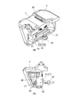
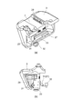
- 5 is a perspective view and a side view showing the internal structure of the front part of the cutter base shown in FIG.
- FIG. 6 is a perspective view showing the count display mechanism shown in FIG.
- FIG. 7 is a perspective view showing a front portion of the cutter base when the fiber holder shown in FIG. 1 is not set in the holder guide portion.
- FIG. 1 is a perspective view showing an embodiment of an optical fiber cutter according to the present invention.
- FIG. 2 is a perspective view showing an internal structure excluding a front portion of the cutter base shown in FIG.
- FIG. 3 is a conceptual diagram showing
- FIG. 8 is a perspective view and a sectional view showing the internal structure of the front portion of the cutter base when the fiber holder shown in FIG. 1 is not set in the holder guide portion.
- FIG. 9 is a perspective view showing the internal structure of the front portion of the cutter base when the fiber holder shown in FIG. 1 is set in the holder guide portion.
- 10 is a perspective view and a cross-sectional view showing the front portion of the cutter base when the fiber holder shown in FIG. 1 is set in the holder guide portion.
- FIG. 11 is a perspective view showing the internal structure of the front portion of the cutter base when the slider shown in FIG. 2 moves toward the initial position.
- FIG. 12 is a perspective view showing the internal structure of the front portion of the cutter base when the slider shown in FIG. 2 further moves toward the initial position.
- FIG. 13 is a perspective view and a cross-sectional view showing a front portion of the cutter base when the slider shown in FIG. 2 further moves toward the initial position.
- FIG. 1 is a perspective view showing an embodiment of an optical fiber cutter according to the present invention.
- an optical fiber cutter 1 according to the present embodiment cuts the exposed glass fiber 2a by removing the coating on the tip portion of the optical fiber 2.
- the optical fiber cutter 1 includes a cutter base 3 and a cutter lid 4 attached to the cutter base 3 so as to be openable and closable.
- the cutter lid 4 is rotatably connected to a rear end portion of the cutter base 3 via a shaft portion 5 extending in the width direction of the cutter base 3.
- a substantially rectangular concave holder guide 7 for positioning the fiber holder 6 holding the optical fiber 2 to be cut is formed on the upper surface of the cutter base 3.
- a claw member 20 is disposed on one side wall side of the holder guide portion 7.
- the claw member 20 protrudes due to a biasing force of a spring (not shown).
- the claw member 20 is pushed to the side wall side and resists against the biasing force of the spring (see FIG. 10).
- a slider 8 is attached to the rear side (shaft part 5 side) of the holder guide part 7 in the cutter base 3.
- the slider 8 is movable in the width direction of the cutter base 3 as shown in FIG.
- a pushing wall 9 is provided at one end of the slider 8.
- An open portion 3 a for exposing the pushing wall portion 9 is formed on one side wall of the cutter base 3.
- a spring 10 (see FIG. 3) for biasing the slider 8 toward the opening 3a is provided.
- the slider 8 is normally in an initial position as shown in FIG. 2B due to the biasing force of the spring 10.
- a disk-shaped blade member 12 that scratches the glass fiber 2a of the optical fiber 2 is rotatably supported on the support wall 11 of the slider 8.
- a circular gear 13 is attached to the blade member 12 so that the blade member 12 and the gear 13 can rotate together.
- An arm member 14 that engages with the gear 13 is provided at a portion of the cutter base 3 opposite to the opening 3 a.
- the slider lid 4 is first opened with respect to the cutter base 3, as shown in FIG.
- the pushing wall part 9 of 8 is pushed in.
- the slider 8 moves to the opposite side of the opening 3a against the biasing force of the spring 10, and reaches the cutting start position.
- the slider 8 is held at the cutting start position by a locking structure (not shown) provided on the cutter base 3.
- the fiber holder 6 holding the optical fiber 2 is set on the holder guide portion 7 of the cutter base 3.
- the optical fiber 2 is positioned with respect to the slider 8 as shown in FIG.
- the count display mechanism 21 is a numerical disk 24 with five gear portions that is rotatably supported by a support 23, and is rotatably supported by the support 23. There are five gears 25 that mesh with the gear portion. Numbers “0”, “1”, “2”... “9” are attached to the outer peripheral surface of the number disk 24 at equal intervals (36 degree intervals).
- the count display mechanism 21 is configured such that when an arbitrary number disk 24 rotates once, the number disk 24 corresponding to the position one above the number disk 24 is counted up by one. As a result, the count display mechanism 21 can display counts one by one from “00000” to “99999”.
- the count display mechanism 21 has a function of resetting the count number to “00000”.
- An auxiliary gear 26 is attached to the gear portion of the numeric disk 24 corresponding to the first place.
- the auxiliary gear 26 rotates together with the numerical disk 24 corresponding to the first place.
- a substantially L-shaped rotation member 27 is rotatably supported on the support body 23. Further, two winding springs 28 (see FIG. 11) for urging the rotating member 27 in a direction that is horizontal with respect to the upper surface and the lower surface of the cutter base 3 are attached to the support body 23.
- Control means for mechanically controlling the count display mechanism 21 is configured so that the count operation by the count display mechanism 21 is validated only when it is set.
- rotational drive means is configured to rotate the count display mechanism 21 by an angle corresponding to one count.
- the optical fiber cutter 1 configured as described above, when the optical fiber 2 is cut, when the slider 8 is pushed and moved to the cutting start position, the fiber holder 6 is still set on the holder guide portion 7. Absent. Therefore, as shown in FIG. 8, the rotating member 27 is inclined by an angle ⁇ with respect to the horizontal state, and the protrusion 32 of the slider 8 hits the slider-side engaging portion 31 of the rotating member 27. There is nothing.
- the protrusion 32 of the slider 8 moves in a state of being in contact with the flat surface 33 a of the slider-side engagement portion 31.
- the rotating member 27 is rotated so that the protrusion 32 pushes up the slider-side engagement portion 31 against the urging force of the winding spring 28. Therefore, as shown in FIGS. 12 and 13, the rotating member 27 is again inclined by the angle ⁇ with respect to the horizontal state.
- the upper locking piece 34 is engaged with the auxiliary gear 26, and the auxiliary gear 26 rotates by a predetermined angle (18 degrees), and accordingly, the number disk 24 corresponding to the first place is only the same angle. Rotate.
- the number disk 24 corresponding to the first place finally rotates by 36 degrees, so that the count display mechanism 21 is counted up by one. That is, every time the optical fiber 2 is cut by returning the slider 8 to the initial position, the count display mechanism 21 is counted up by one.
- the numerical disk 24 is rotated by the same angle. Since the amount of movement of the upper locking piece 34 and the lower locking piece 35 can be reduced, the optical fiber cutter 1 can be finally downsized.
- the number of times the slider 8 returns to the initial position is counted only when the fiber holder 6 is set to the holder guide portion 7 and the claw member 20 is pushed to the side wall. Since the counting is performed by the display mechanism 21, the count display mechanism 21 does not count the number of times the slider 8 returns to the initial position when the fiber holder 6 is not set in the holder guide portion 7. Thereby, in the count display mechanism 21, the frequency
- the display color may be changed according to the count number of the count display mechanism 21 to prompt the replacement of the blade member 12. For example, until the count number reaches “50000”, the display color is green, and when the count number reaches “50000”, the display color of “tens of thousands” is changed to orange, and the count number is “60000”. When the value is over, the display color is changed to red.
- a structure is provided in which a stopper is provided so that the blade member 12 does not slide so that the blade member 12 is always replaced.
Landscapes
- Physics & Mathematics (AREA)
- General Physics & Mathematics (AREA)
- Optics & Photonics (AREA)
- Life Sciences & Earth Sciences (AREA)
- Forests & Forestry (AREA)
- Engineering & Computer Science (AREA)
- Mechanical Engineering (AREA)
- Light Guides In General And Applications Therefor (AREA)
Abstract
Priority Applications (6)
| Application Number | Priority Date | Filing Date | Title |
|---|---|---|---|
| KR1020147006466A KR101644719B1 (ko) | 2011-08-12 | 2012-08-03 | 광섬유 커터 |
| SG2014010987A SG2014010987A (en) | 2011-08-12 | 2012-08-03 | Optical fiber cutter |
| CA2844816A CA2844816C (fr) | 2011-08-12 | 2012-08-03 | Organe de coupe de fibre optique |
| EP12823861.5A EP2743741B1 (fr) | 2011-08-12 | 2012-08-03 | Organe de coupe de fibre optique |
| CN201280039503.9A CN103733098B (zh) | 2011-08-12 | 2012-08-03 | 光纤切断器 |
| US14/238,295 US9678274B2 (en) | 2011-08-12 | 2012-08-03 | Optical fiber cutter |
Applications Claiming Priority (2)
| Application Number | Priority Date | Filing Date | Title |
|---|---|---|---|
| JP2011176989A JP5797972B2 (ja) | 2011-08-12 | 2011-08-12 | 光ファイバカッタ |
| JP2011-176989 | 2011-08-12 |
Publications (1)
| Publication Number | Publication Date |
|---|---|
| WO2013024723A1 true WO2013024723A1 (fr) | 2013-02-21 |
Family
ID=47715045
Family Applications (1)
| Application Number | Title | Priority Date | Filing Date |
|---|---|---|---|
| PCT/JP2012/069898 Ceased WO2013024723A1 (fr) | 2011-08-12 | 2012-08-03 | Organe de coupe de fibre optique |
Country Status (9)
| Country | Link |
|---|---|
| US (1) | US9678274B2 (fr) |
| EP (1) | EP2743741B1 (fr) |
| JP (1) | JP5797972B2 (fr) |
| KR (1) | KR101644719B1 (fr) |
| CN (1) | CN103733098B (fr) |
| CA (1) | CA2844816C (fr) |
| MY (1) | MY166159A (fr) |
| SG (1) | SG2014010987A (fr) |
| WO (1) | WO2013024723A1 (fr) |
Cited By (1)
| Publication number | Priority date | Publication date | Assignee | Title |
|---|---|---|---|---|
| JP6154973B1 (ja) * | 2017-02-24 | 2017-06-28 | 株式会社フジクラ | 被覆除去装置 |
Families Citing this family (6)
| Publication number | Priority date | Publication date | Assignee | Title |
|---|---|---|---|---|
| KR101826654B1 (ko) * | 2012-02-20 | 2018-02-07 | 이노 인스트루먼트 (차이나). 인코퍼레이션 | 광섬유 절단기 |
| USD745816S1 (en) * | 2013-12-16 | 2015-12-22 | Dh Infotech (Weihai) Inc. | Optical fiber cleaver |
| JP6611008B2 (ja) * | 2016-02-29 | 2019-11-27 | Seiオプティフロンティア株式会社 | 光ファイバカッタ |
| JP6639955B2 (ja) * | 2016-02-29 | 2020-02-05 | Seiオプティフロンティア株式会社 | 光ファイバカッタ |
| JPWO2021230115A1 (fr) | 2020-05-12 | 2021-11-18 | ||
| CN115390191A (zh) * | 2022-08-30 | 2022-11-25 | 藤野(成都)科技有限公司 | 一种带计数显示的光纤切割刀 |
Citations (4)
| Publication number | Priority date | Publication date | Assignee | Title |
|---|---|---|---|---|
| JPS54130462U (fr) * | 1978-03-02 | 1979-09-10 | ||
| JPH0262405U (fr) | 1988-10-25 | 1990-05-10 | ||
| JP2008203815A (ja) | 2007-01-23 | 2008-09-04 | Sumitomo Electric Ind Ltd | 光ファイバ切断装置 |
| JP2009119117A (ja) * | 2007-11-16 | 2009-06-04 | Sumitomo Electric Ind Ltd | 医療用光源装置使用方法 |
Family Cites Families (13)
| Publication number | Priority date | Publication date | Assignee | Title |
|---|---|---|---|---|
| JPS54130462A (en) | 1978-03-31 | 1979-10-09 | Sumitomo Metal Ind Ltd | Cold drawing method for steel pipe with fin of irregular shape |
| US4421000A (en) * | 1981-05-15 | 1983-12-20 | Murphy Ina H | Hole punching device |
| FR2550862A1 (fr) * | 1983-08-18 | 1985-02-22 | Telecommunications Sa | Dispositif de coupe pour fibres optiques |
| US4637289A (en) * | 1984-11-02 | 1987-01-20 | Whirlwind, Inc. | Work presence controller |
| JPH0262405A (ja) | 1988-08-26 | 1990-03-02 | Diesel Kiki Co Ltd | 油圧制御装置 |
| JP3497998B2 (ja) * | 1998-12-22 | 2004-02-16 | 日立電線株式会社 | 光ファイバテープ心線の被覆層切削工具及び被覆層除去方法 |
| JP2000301487A (ja) * | 1999-04-21 | 2000-10-31 | Nippon Sheet Glass Co Ltd | カッター装置 |
| US7305169B2 (en) | 2004-03-15 | 2007-12-04 | Sumitomo Electric Industries, Ltd. | Fiber cleaver |
| JP4383289B2 (ja) | 2004-08-18 | 2009-12-16 | 古河電気工業株式会社 | 光ファイバ切断装置、光ファイバ融着接続機、光ファイバ切断接続システム、光ファイバ加工管理方法、光ファイバ把持具及び光ファイバ補強装置 |
| CN201107427Y (zh) * | 2007-10-31 | 2008-08-27 | 佛山市顺德区汉达精密电子科技有限公司 | 一种光纤切割装置 |
| KR20090081179A (ko) * | 2008-01-23 | 2009-07-28 | 일신테크(주) | 광섬유 절단기 |
| US8998682B2 (en) * | 2011-09-28 | 2015-04-07 | Ksaria Corporation | Devices and methods for automatically cleaving and abrading cables |
| WO2014168758A1 (fr) * | 2013-04-08 | 2014-10-16 | 3M Innovative Properties Company | Coupe-fibre optique jetable de faible coût et procédé permettant de couper une fibre optique |
-
2011
- 2011-08-12 JP JP2011176989A patent/JP5797972B2/ja active Active
-
2012
- 2012-08-03 WO PCT/JP2012/069898 patent/WO2013024723A1/fr not_active Ceased
- 2012-08-03 SG SG2014010987A patent/SG2014010987A/en unknown
- 2012-08-03 US US14/238,295 patent/US9678274B2/en active Active
- 2012-08-03 CN CN201280039503.9A patent/CN103733098B/zh active Active
- 2012-08-03 MY MYPI2014000364A patent/MY166159A/en unknown
- 2012-08-03 EP EP12823861.5A patent/EP2743741B1/fr active Active
- 2012-08-03 CA CA2844816A patent/CA2844816C/fr active Active
- 2012-08-03 KR KR1020147006466A patent/KR101644719B1/ko active Active
Patent Citations (4)
| Publication number | Priority date | Publication date | Assignee | Title |
|---|---|---|---|---|
| JPS54130462U (fr) * | 1978-03-02 | 1979-09-10 | ||
| JPH0262405U (fr) | 1988-10-25 | 1990-05-10 | ||
| JP2008203815A (ja) | 2007-01-23 | 2008-09-04 | Sumitomo Electric Ind Ltd | 光ファイバ切断装置 |
| JP2009119117A (ja) * | 2007-11-16 | 2009-06-04 | Sumitomo Electric Ind Ltd | 医療用光源装置使用方法 |
Non-Patent Citations (1)
| Title |
|---|
| See also references of EP2743741A4 * |
Cited By (4)
| Publication number | Priority date | Publication date | Assignee | Title |
|---|---|---|---|---|
| JP6154973B1 (ja) * | 2017-02-24 | 2017-06-28 | 株式会社フジクラ | 被覆除去装置 |
| WO2018154792A1 (fr) * | 2017-02-24 | 2018-08-30 | 株式会社フジクラ | Dispositif d'enlèvement de revêtement |
| JP2018138970A (ja) * | 2017-02-24 | 2018-09-06 | 株式会社フジクラ | 被覆除去装置 |
| US10459164B2 (en) | 2017-02-24 | 2019-10-29 | Fujikura Ltd. | Coating removing device |
Also Published As
| Publication number | Publication date |
|---|---|
| SG2014010987A (en) | 2014-04-28 |
| JP2013041042A (ja) | 2013-02-28 |
| EP2743741A4 (fr) | 2015-03-25 |
| KR20140051409A (ko) | 2014-04-30 |
| CN103733098B (zh) | 2016-08-17 |
| CN103733098A (zh) | 2014-04-16 |
| US9678274B2 (en) | 2017-06-13 |
| CA2844816C (fr) | 2018-11-20 |
| CA2844816A1 (fr) | 2013-02-21 |
| EP2743741B1 (fr) | 2017-01-04 |
| KR101644719B1 (ko) | 2016-08-01 |
| EP2743741A1 (fr) | 2014-06-18 |
| MY166159A (en) | 2018-06-07 |
| US20140151425A1 (en) | 2014-06-05 |
| JP5797972B2 (ja) | 2015-10-21 |
Similar Documents
| Publication | Publication Date | Title |
|---|---|---|
| JP5797972B2 (ja) | 光ファイバカッタ | |
| US9229166B2 (en) | Optical fiber cutter, and optical fiber cutter unit | |
| JP4956474B2 (ja) | 光ファイバ切断装置 | |
| CA3014522C (fr) | Organe de coupe de fibre optique | |
| WO2019117139A1 (fr) | Organe de coupe de fibre optique et procédé de coupe de fibre optique | |
| JP2008185728A (ja) | レンズ鏡筒およびレンズ鏡筒を備える撮像装置 | |
| US20190064440A1 (en) | Optical fiber cutter | |
| JPS59227064A (ja) | 磁気デイスク装置 | |
| JP2693013B2 (ja) | 磁気記録再生装置 | |
| JP5911617B1 (ja) | スロットマシンにおけるリールユニットのロック機構 | |
| JPH0562322A (ja) | デイスク装置 | |
| JP3092303B2 (ja) | ディスク装置 | |
| JPH0450595Y2 (fr) | ||
| JP2689677B2 (ja) | 磁気記録再生装置 | |
| JP2689678B2 (ja) | 磁気記録再生装置 | |
| JPH0760547B2 (ja) | 磁気記録再生装置 | |
| JP2689679B2 (ja) | 磁気記録再生装置 | |
| US6503001B1 (en) | Shutter driving mechanism for camera | |
| JP2008204559A (ja) | ディスク駆動装置 | |
| EP1418464A1 (fr) | Dispositif de commande d'un obturateur pour une caméra | |
| JPH09306074A (ja) | 光ディスクドライブ装置 | |
| JPH0785323B2 (ja) | 磁気記録再生装置 | |
| JPH06267171A (ja) | ディスク装置 | |
| JPH11142932A (ja) | カートリッジ室の蓋の開閉機構 | |
| JPS59168427A (ja) | カメラのフイルム巻戻用開口の開閉装置 |
Legal Events
| Date | Code | Title | Description |
|---|---|---|---|
| 121 | Ep: the epo has been informed by wipo that ep was designated in this application |
Ref document number: 12823861 Country of ref document: EP Kind code of ref document: A1 |
|
| ENP | Entry into the national phase |
Ref document number: 2844816 Country of ref document: CA |
|
| WWE | Wipo information: entry into national phase |
Ref document number: 14238295 Country of ref document: US |
|
| NENP | Non-entry into the national phase |
Ref country code: DE |
|
| REEP | Request for entry into the european phase |
Ref document number: 2012823861 Country of ref document: EP |
|
| WWE | Wipo information: entry into national phase |
Ref document number: 2012823861 Country of ref document: EP |
|
| ENP | Entry into the national phase |
Ref document number: 20147006466 Country of ref document: KR Kind code of ref document: A |