WO2018154792A1 - Dispositif d'enlèvement de revêtement - Google Patents
Dispositif d'enlèvement de revêtement Download PDFInfo
- Publication number
- WO2018154792A1 WO2018154792A1 PCT/JP2017/008491 JP2017008491W WO2018154792A1 WO 2018154792 A1 WO2018154792 A1 WO 2018154792A1 JP 2017008491 W JP2017008491 W JP 2017008491W WO 2018154792 A1 WO2018154792 A1 WO 2018154792A1
- Authority
- WO
- WIPO (PCT)
- Prior art keywords
- unit
- heating
- coating
- gripping
- coating removal
- Prior art date
- Legal status (The legal status is an assumption and is not a legal conclusion. Google has not performed a legal analysis and makes no representation as to the accuracy of the status listed.)
- Ceased
Links
Images






Classifications
-
- G—PHYSICS
- G02—OPTICS
- G02B—OPTICAL ELEMENTS, SYSTEMS OR APPARATUS
- G02B6/00—Light guides; Structural details of arrangements comprising light guides and other optical elements, e.g. couplings
- G02B6/24—Coupling light guides
- G02B6/245—Removing protective coverings of light guides before coupling
-
- H—ELECTRICITY
- H02—GENERATION; CONVERSION OR DISTRIBUTION OF ELECTRIC POWER
- H02G—INSTALLATION OF ELECTRIC CABLES OR LINES, OR OF COMBINED OPTICAL AND ELECTRIC CABLES OR LINES
- H02G1/00—Methods or apparatus specially adapted for installing, maintaining, repairing or dismantling electric cables or lines
- H02G1/12—Methods or apparatus specially adapted for installing, maintaining, repairing or dismantling electric cables or lines for removing insulation or armouring from cables, e.g. from the end thereof
- H02G1/1202—Methods or apparatus specially adapted for installing, maintaining, repairing or dismantling electric cables or lines for removing insulation or armouring from cables, e.g. from the end thereof by cutting and withdrawing insulation
-
- H—ELECTRICITY
- H02—GENERATION; CONVERSION OR DISTRIBUTION OF ELECTRIC POWER
- H02G—INSTALLATION OF ELECTRIC CABLES OR LINES, OR OF COMBINED OPTICAL AND ELECTRIC CABLES OR LINES
- H02G1/00—Methods or apparatus specially adapted for installing, maintaining, repairing or dismantling electric cables or lines
- H02G1/12—Methods or apparatus specially adapted for installing, maintaining, repairing or dismantling electric cables or lines for removing insulation or armouring from cables, e.g. from the end thereof
- H02G1/1202—Methods or apparatus specially adapted for installing, maintaining, repairing or dismantling electric cables or lines for removing insulation or armouring from cables, e.g. from the end thereof by cutting and withdrawing insulation
- H02G1/1204—Hand-held tools
- H02G1/1207—Hand-held tools the cutting element not rotating about the wire or cable
- H02G1/1209—Hand-held tools the cutting element not rotating about the wire or cable making a transverse cut
-
- H—ELECTRICITY
- H02—GENERATION; CONVERSION OR DISTRIBUTION OF ELECTRIC POWER
- H02G—INSTALLATION OF ELECTRIC CABLES OR LINES, OR OF COMBINED OPTICAL AND ELECTRIC CABLES OR LINES
- H02G1/00—Methods or apparatus specially adapted for installing, maintaining, repairing or dismantling electric cables or lines
- H02G1/12—Methods or apparatus specially adapted for installing, maintaining, repairing or dismantling electric cables or lines for removing insulation or armouring from cables, e.g. from the end thereof
- H02G1/1202—Methods or apparatus specially adapted for installing, maintaining, repairing or dismantling electric cables or lines for removing insulation or armouring from cables, e.g. from the end thereof by cutting and withdrawing insulation
- H02G1/1204—Hand-held tools
- H02G1/1236—Features relating to cutting elements
- H02G1/1241—Features relating to cutting elements the cutting element being a stack of blades
-
- H—ELECTRICITY
- H02—GENERATION; CONVERSION OR DISTRIBUTION OF ELECTRIC POWER
- H02G—INSTALLATION OF ELECTRIC CABLES OR LINES, OR OF COMBINED OPTICAL AND ELECTRIC CABLES OR LINES
- H02G1/00—Methods or apparatus specially adapted for installing, maintaining, repairing or dismantling electric cables or lines
- H02G1/12—Methods or apparatus specially adapted for installing, maintaining, repairing or dismantling electric cables or lines for removing insulation or armouring from cables, e.g. from the end thereof
- H02G1/1275—Methods or apparatus specially adapted for installing, maintaining, repairing or dismantling electric cables or lines for removing insulation or armouring from cables, e.g. from the end thereof by applying heat
Definitions
- the present invention relates to an optical fiber coating removal apparatus.
- devices disclosed in Patent Documents 1 and 2 are known as coating removal devices for removing the coating of an optical fiber.
- the coating to be removed of the optical fiber is heated and softened, and the adhesion between the bare optical fiber and the coating is reduced to remove the coating. Yes.
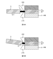
- FIG. 16A is an explanatory diagram of how the coating is removed.
- the gripping part (not shown: described later) that grips the optical fiber 3 on the left side in the figure is moved to cover the blades 21A and 23A.
- the coating 5 of the optical fiber 3 is removed. Since it is necessary to hook the coating 5 with the blades 21A and 23A when removing the coating 5, the distance between the pair of blades 21A and 23A is narrower than the thickness of the coating 5 (the diameter of the optical fiber 3). It is set slightly wider than the diameter of 4.
- the bare optical fiber 4 moves up and down when the coating 5 is pulled out, and the blades 21A and 23A come into contact with the bare optical fiber 4. Sometimes. For this reason, in order to suppress damage to the bare optical fiber 4, the hardness of the blades 21 ⁇ / b> A and 23 ⁇ / b> A is set lower than the hardness of the bare optical fiber 4. As a result, when the removal of the coating 5 is repeated, the cutting edge is gradually worn.
- the coating 5 is removed while one blade (the lower blade 21A in the drawing) is worn, the timing at which the worn blade 21A tears the coating 5 is delayed. At the same time, slippage occurs between the worn blade 21 ⁇ / b> A and the coating 5, resulting in a problem that the balance of the force applied to the bare optical fiber 4 is lost. When the balance of the force applied to the bare optical fiber 4 is lost, the bare optical fiber 4 is bent, or the bare optical fiber 4 is excessively pressed by the upper blade 23A. May reduce reliability.
- Some embodiments of the present invention are directed to prompting blade replacement when the blade is worn.
- Some embodiments of the invention include: A heating unit having a heater unit for heating the coating of the optical fiber, and a blade for cutting the coating of the optical fiber; A gripper that grips the optical fiber and is movable relative to the heating unit; The coating removing apparatus includes a counting unit that counts the number of coating removals by detecting the separation between the heating unit and the gripping unit.
- FIG. 9 is an explanatory diagram of the counting process of the number of coating removals according to the second embodiment.
- FIG. 10 is a block diagram illustrating a configuration of the coating removal apparatus 10 according to the third embodiment.
- 11A and 11B are explanatory diagrams of the holder detection unit 54.
- FIG. 12 is an explanatory diagram of a counting process of the number of coating removals according to the third embodiment.
- FIG. 13A is an explanatory diagram of the separation detection unit 52 of the fourth embodiment.
- FIG. 13B is an explanatory diagram of a separation detection unit 52 according to a modification of the fourth embodiment.
- FIG. 14 is an explanatory diagram of the counting process of the number of coating removals according to the fifth embodiment.
- 15A and 15B are explanatory diagrams of a configuration example of the proximity holding unit.
- FIG. 16A is an explanatory diagram of how the coating is removed.
- FIG. 16B is an explanatory diagram of how the coating is removed when the blade is worn.
- a heating unit having a heater unit for heating the coating of the optical fiber and a blade for cutting the coating of the optical fiber; a gripping unit that grips the optical fiber and is movable with respect to the heating unit; By detecting the separation between the heating unit and the gripping unit, a coating removal apparatus including a counting unit that counts the number of coating removals becomes clear. According to such a coating removal apparatus, the number of coating removals can be counted, and replacement of the blade can be promoted when the blade is worn.
- the counting unit counts the number of coating removals when detecting the closed state of the lid of the heating unit and detecting the separation between the heating unit and the gripping unit. Thereby, even if the separation between the heating unit and the gripping unit is detected when the lid is in the open state, the coating removal count is not counted, and thus the counting accuracy of the coating removal count can be increased.
- the counting unit permits the next counting of the number of coating removals when the open state of the lid of the heating unit is detected after counting the number of times of coating removal. Thereby, the counting accuracy of the number of coating removals can be increased.
- the counting unit counts the number of coating removals when detecting the heating of the heater unit of the heating unit and detecting the separation between the heating unit and the gripping unit. As a result, even if the separation between the heating unit and the gripping unit is detected when the heater unit is not heated, the coating removal count is not counted, so the counting accuracy of the coating removal count can be increased.
- the shaft includes a shaft that connects the heating unit and the gripping unit and guides the separation between the heating unit and the gripping unit, and a movement amount of the shaft when the heating unit and the gripping unit are separated from each other. It is desirable to detect the separation between the heating unit and the gripping unit by detecting that the predetermined amount has been reached. Thereby, unless the heating part and the grip part are separated from each other by a predetermined amount or more, the number of times of coating removal is not counted, and thus the accuracy of counting the number of times of coating removal can be increased.
- the proximity holding unit maintains a state in which the heating unit and the gripping unit are brought close to each other using magnetic force, and the heating unit and the gripping unit are separated from each other using the magnetic force of the proximity holding unit. It is desirable to detect Thereby, the number of parts can be reduced.
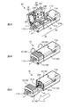
- FIG. 1 is an overall perspective view of a coating removing apparatus 10 according to the present embodiment.
- FIG. 2A to FIG. 2C are explanatory views of the state when the coating is removed.
- the coating removal device 10 is a device that removes the coating of the optical fiber.
- the object of the coating removal is the optical fiber tape 1 having a plurality of optical fibers 3 here, but may be a single-core optical fiber.
- the coating removal apparatus 10 of the present embodiment heats and softens the coating material 5 (hereinafter simply referred to as coating) that coats the outer periphery of the bare optical fiber 4 (see FIG. 16A), and adheres the bare optical fiber 4 to the coating.
- the coating removal apparatus 10 of this embodiment may be called a hot jacket stripper.
- the moving direction of the main body part and the grip part 30 is the front-rear direction
- the main body part side is “front”
- the grip part 30 side is “rear”.
- the front-rear direction may be referred to as a “separation direction”, a “proximity direction”, or a “slide direction”.
- the direction perpendicular to the bottom surface of the holder accommodating portion 311 of the gripping portion 30 is defined as “up and down direction”, and the side in which the holder 7 is accommodated is “upward” when viewed from the bottom surface of the holder accommodating portion 311.
- the side of the main body 31) is “down”.
- the coating removal apparatus 10 includes a heating unit 20 and a gripping unit 30.
- the heating unit 20 is a member that heats the coating of the optical fiber.
- the heating unit 20 has a pair of blades 21A and 23A for removing the coating.
- the heating unit 20 includes a heating side main body 21 and a heating side lid part 23, and a blade is provided on each of the heating side main body 21 and the heating side lid part 23.
- the heating side main body 21 is a member constituting the main body of the heating unit 20.
- the heating side main body 21 includes a blade 21 ⁇ / b> A and a heater unit 211.
- the blade 21A is a member that cuts the coating and removes the coating by hooking.
- the heater unit 211 is a heat source for heating the coating of the optical fiber.
- the heater unit 211 also has a function as a mounting unit for mounting the end of the optical fiber. Specifically, the heater 211 is formed in a groove shape along the front-rear direction, and the end of the optical fiber can be placed in a state where the end of the optical fiber is guided in the front-rear direction.
- the heating-side main body 21 is provided with a power switch 21B, an LED lamp 71A (output unit 71), and the like.
- the heating side lid portion 23 is a lid member that can be opened and closed with respect to the heating side main body 21.
- the heating side lid part 23 has a blade 23 ⁇ / b> A and a holding part 231.
- the holding part 231 is a part for holding the end part of the optical fiber by sandwiching the end part of the optical fiber with the heater part 211 of the heating side main body 21.
- the heating-side lid portion 23 may also be provided with a heat source (heater portion 211) for heating the coating of the optical fiber.
- the grip portion 30 is a member that grips the optical fiber.
- the gripper 30 grips the optical fiber by gripping the holder 7 that holds the optical fiber.
- the grip portion 30 may grip the optical fiber indirectly through a member other than the holder 7 or may directly grip the optical fiber.
- the grip part 30 is configured to be movable in the front-rear direction with respect to the heating part 20 (see FIG. 2C).
- the grip portion 30 includes a grip side main body 31 and a grip side lid portion 33.
- the grip side main body 31 is a member constituting the main body of the grip portion 30.
- the grip-side main body 31 has a holder accommodating portion 311.
- the holder accommodating portion 311 is a portion that accommodates the holder 7 holding the optical fiber.
- the grip-side lid portion 33 is a lid member that can be opened and closed with respect to the grip-side main body 31.
- the grip side lid portion 33 has a holder holding portion 331.
- the holder holding part 331 is a part for holding the holder 7 by sandwiching the holder 7 holding the optical fiber with the holding-side main body 31.
- the heating unit 20 and the gripping unit 30 are connected via a shaft 41 (see FIG. 2C).
- the shaft 41 is a member that connects the heating unit 20 and the gripping unit 30 and guides relative movement between the heating unit 20 and the gripping unit 30.
- one end of the shaft 41 is fixed to the grip portion 30, and when the grip portion 30 moves relative to the heating portion 20, the shaft 41 also moves relative to the heating portion 20.
- the shaft 41 may be fixed to the heating unit 20 side.
- the operator turns on the power switch 21B of the coating removal apparatus 10, and then opens the heating side lid 23 and the grip side lid 33 as shown in FIG. 2A.
- the holder 7 holding the optical fiber 3 here, the optical fiber tape 1 is accommodated in the holder accommodating portion 311 of the grip portion 30, and the end portion of the optical fiber 3 is placed on the heater portion 211 of the heating side main body 21. .
- the optical fiber 3 is set in the coating removal apparatus 10.
- the operator closes the heating side lid 23 and the grip side lid 33 as shown in FIG. 2B.
- the heating side lid 23 is closed, the pair of blades 21A and 23A cuts the coating of the optical fiber 3.
- the heating-side lid portion 23 is closed, the end portion of the optical fiber 3 is sandwiched between the heater portion 211 of the heating-side main body 21 and the holding portion 231 of the heating-side lid portion 23, and the end portion of the optical fiber 3.
- the coating is heated by the heater unit 211.
- the lid detection unit 51 detects the closed state of the heating side lid unit 23, heating of the heater unit 211 is started.
- the coating at the end of the optical fiber is heated, the coating is softened, the adhesion between the bare optical fiber 4 and the coating is reduced, and the coating is easily removed.
- the worker moves the gripping part 30 to the rear side with respect to the heating part 20 with the heating-side cover part 23 and the gripping-side cover part 33 closed. And the grip portion 30 are separated. As a result, the coating at the end of the optical fiber is pulled out by the pair of blades 21A and 23A (see FIG. 16A), and the coating of the optical fiber is removed.
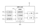
- FIG. 3 is a block diagram showing the configuration of the coating removal apparatus 10.
- the coating removal apparatus 10 includes a control unit 61, various detection units (such as a lid detection unit 51), and an output unit 71 (such as an LED lamp 71A).
- the control unit 61 has a function of controlling the coating removal apparatus 10.
- the control unit 61 includes, for example, an arithmetic processing device or a storage device, and various processing is realized by the arithmetic processing device executing a program stored in the storage device. Detection results of various detection units are input to the control unit 61.
- the control unit 61 controls the heater unit 211 and the output unit 71 based on the detection results of the various detection units.
- the lid detector 51 is a member that detects opening and closing of the heating side lid 23.
- the lid detector 51 has a protruding piece 23B (see FIG. 1) provided on the heating side lid 23.
- a switch, a sensor, or the like of the heating side body 21 is provided.
- a detection unit (not shown in FIG. 1; see FIGS. 4A to 4C) detects the protruding piece 23B, thereby detecting that the heating-side lid unit 23 is closed (closed state).
- 4A to 4C are explanatory diagrams of a configuration example of the lid detection unit 51 (51A to 51C).
- the protruding piece 23B (see FIG. 1) of the heating side lid 23 turns on / off the switch (detection unit) of the heating side body 21 in response to opening and closing of the heating side lid 23.
- the closed state (and open state) of the heating side cover part 23 is detected.
- a magnet sensor (detection unit) is provided on the heating-side main body 21, a magnet is provided on the protruding piece 23B of the heating-side lid 23, and a heating-side lid unit is illustrated.
- the closed state (and the open state) of the heating side lid portion 23 is detected by the change in magnetism detected by the magnet sensor (detection portion) according to the opening and closing of the 23.
- the protruding piece 23B (see FIG. 1) of the heating side lid part 23 detects the detection light of the photo sensor (detection unit) of the heating side body 21 in response to opening and closing of the heating side lid part 23. By blocking, the closed state (and open state) of the heating side lid 23 is detected.
- the lid detection unit 51 is not limited to the above configuration as long as it can detect the closed state (or open state) of the heating side lid unit 23.
- the detection result of the lid detection unit 51 is output to the control unit 61.
- the controller 61 detects the closed state of the heating side lid 23 based on the detection result of the lid detector 51
- the controller 61 causes the heater 211 to start heating.
- the control unit 61 stops the heating of the heater unit 211 when detecting the open state of the heating side lid unit 23 based on the detection result of the lid detection unit 51.
- the control unit 61 serves as a heating control unit that controls the heater unit 211.
- the controller 61 detects the closed state of the heating side lid 23 based on the detection result of the lid detector 51, the controller 61 turns on the LED lamp 71A (output unit 71) after a predetermined time has elapsed. Accordingly, it is possible to notify the worker that the coating on the end of the optical fiber has been heated, or to prompt the worker to move the grip portion 30 shown in FIG. 2C.
- the control unit 61 is an output control unit that controls the output unit 71.
- the covering removal apparatus 10 includes, as the output unit 71, a display unit such as an LED lamp 71A, a speaker (not shown) that outputs sound, and the like. As will be described later, the LED lamp 71A and the speaker (not shown) serve as a notification unit that notifies that the number of coating removals has reached a predetermined value.
- the covering removal apparatus 10 may include a display unit capable of displaying a numerical value (for example, a count value described later) as the output unit 71.
- a display unit capable of displaying a numerical value for example, a count value described later
- examples of the display unit (output unit 71) capable of displaying a count value include a small liquid crystal monitor capable of displaying information other than numerical values, and a segment display device whose main purpose is to display numerical values.
- the coating removal apparatus 10 may include a communication unit that transmits and receives data (data including a count value described later) to an external device as the output unit 71.
- the coating removal apparatus 10 includes a separation detection unit 52 for detecting separation between the heating unit 20 and the grip unit 30 (see FIG. 3).
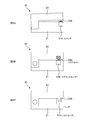
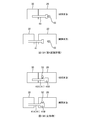
- 5A to 5C are explanatory diagrams of a configuration example of the separation detection unit 52 (52A to 52C).
- the separation detector 52A shown in FIG. 5A is configured by a mechanical switch.
- 5A is an explanatory diagram of a state (proximity state) before the separation detection unit 52A detects the separation between the heating unit 20 and the grip unit 30.
- FIG. The lower diagram of FIG. 5A is an explanatory diagram of a state (separation state) in which the separation detection unit 52A detects the separation between the heating unit 20 and the gripping unit 30.
- the separation detection unit 52A illustrated in FIG. 5A turns on / off the switch (detection unit) of the heating-side main body 21 in accordance with the proximity / separation of the heating unit 20 and the gripping unit 30, thereby causing the heating unit 20 and the gripping unit 30.
- the separation state (or proximity state) is detected.
- the separation detection unit 52 ⁇ / b> A is disposed on the opposing surface of the heating unit 20 and the grip unit 30.
- the switch that constitutes the separation detection unit 52A is disposed in the heating unit 20, and the switch is turned on / off when the facing surface (detected unit) of the gripping unit 30 contacts / separates the switch.
- the switch constituting the separation detection unit 52A may be disposed on the grip unit 30 side.
- the separation detection unit 52B shown in FIG. 5B is configured by a magnet sensor.
- the heating-side main body 21 is provided with a magnet sensor (detection part), and the grip part 30 is provided with a magnet (detected part).
- the separation detection unit 52A shown in FIG. 5B is a separation state between the heating unit 20 and the gripping unit 30 due to a change in magnetism detected by the magnet sensor (detection unit) according to the proximity and separation between the heating unit 20 and the gripping unit 30. (Or proximity state) is detected.
- the separation detection unit 52C shown in FIG. 5C is configured by a photosensor.
- the heating-side main body 21 is provided with a photosensor (detecting unit), and the gripping unit 30 is provided with a light shielding piece (detected portion).
- the light shielding piece blocks or projects the detection light of the photosensor (detection unit) according to the proximity / separation of the heating unit 20 and the gripping unit 30, thereby separating (or approaching) the heating unit 20 and the gripping unit 30. Status).
- the separation detection unit 52 only needs to detect the separation state (or proximity state) between the heating unit 20 and the gripping unit 30. Therefore, the separation detection unit 52 is not limited to the configuration shown in FIGS. 5A to 5C.
- the coating removal apparatus 10 includes a counting unit 61A that counts the number of coating removals (see FIG. 3).
- the count unit 61A is configured by the control unit 61, but may be configured by a mechanical counter.
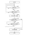
- FIG. 6 is an explanatory diagram of the counting process of the number of coating removals according to the first embodiment.
- the count unit 61A determines whether or not the closed state of the heating side lid unit 23 is detected based on the detection result of the lid detection unit 51 (S101). If the count part 61A does not detect the closed state of the heating side lid part 23 (NO in S101), the counting part 61A repeats the determination process of S101 until the closed state of the heating side lid part 23 is detected.
- the counting unit 61 ⁇ / b> A detects the closed state of the heating-side lid unit 23 (YES in S ⁇ b> 101)
- the counting unit 61 ⁇ / b> A next detects the separation state between the heating unit 20 and the gripping unit 30 based on the detection result of the separation detection unit 52. It is determined whether or not (S102).
- the count unit 61A If the count unit 61A does not detect the separation state between the heating unit 20 and the gripping unit 30 based on the detection result of the separation detection unit 52 (NO in S102), the count unit 61A returns to the determination process in S101.
- the counting unit 61A detects the separation state between the heating unit 20 and the gripping unit 30 based on the detection result of the separation detection unit 52 (YES in S102), the count unit 61A adds one count value of the number of coating removals (S103). .
- the counting unit 61A detects the closed state of the heating side lid 23 based on the detection result of the lid detection unit 51 (YES in S101), and the detection result of the separation detection unit 52 Based on this, when the separation state between the heating unit 20 and the gripping unit 30 is detected (YES in S102), the count value of the number of coating removals is incremented by one (S103). As a result, as shown in FIG. 2C, the worker moves the grip 30 to the rear side with respect to the heating unit 20 with the heating side lid 23 and the grip side lid 33 closed. When the grip part 30 is separated (when the coating at the end of the optical fiber is removed), the count value indicating the number of times of coating removal can be increased by one. In the present embodiment, the count unit 61A stores the count value in the storage device.
- the fact that the closed state of the heating-side lid portion 23 is detected (S101) becomes a count value addition condition, so that the count value increases when the coating is not removed. Since this can be suppressed, the counting accuracy of the coating removal count (coincidence accuracy between the coating removal count and the count value) can be increased.
- the count unit 61A counts the next number of times of coating removal (S101) when detecting the open state of the heating side lid 23 (YES in S105). To S103). That is, in this embodiment, after adding one count value (S103), if the open state of the heating side lid 23 is not detected (YES in S105), the next coating removal count is counted. I will not. In order to remove the coating on the end of the next optical fiber, after removing the coating on the end of the optical fiber as shown in FIG. This is because it is necessary to open the portion 23 (and the grip side lid portion 33). Further, after removing the coating at the end of the optical fiber as shown in FIG.
- the control unit 61 when the count value reaches a predetermined value (YES in S104), the control unit 61 notifies the output unit 71 that the number of times of covering removal has reached the predetermined value. Specifically, when the count value reaches a predetermined value (YES in S104), the control unit 61 turns on the LED lamp 71A, which is the output unit 71, and confirms that the number of times of coating removal has reached the predetermined value. (S106). Thereby, when the blades 21A and 23A are worn, it is possible to prompt the operator to replace the blades 21A and 23A. Note that the notification method of the output unit 71 is not limited to the lighting of the LED lamp 71A.
- the control unit 61 sounds a buzzer with a speaker serving as the output unit 71, thereby informing the operator that the number of times of covering removal has reached the predetermined value. You may notify.
- the control unit 61 may display the count value of the number of coating removals on the display unit (output unit 71).
- the display of the count value is not limited to the electronic display, but may be a mechanical display (for example, a dial display).
- the control unit 61 does not have to determine whether or not the count value has reached a predetermined value (S104) or perform notification (S106) using the output unit 71.
- the counting unit 61A detects the closed state of the heating side lid 23 based on the detection result of the lid detection unit 51 (YES in S101), and based on the detection result of the separation detection unit 52.
- the count value of the number of coating removals was added by 1 (S103).
- FIG. 7 is an explanatory diagram of the heating profile of the heater unit 211.
- the horizontal axis of the graph in the figure indicates time, and the vertical axis indicates the temperature of the heater unit 211.
- the control unit 61 (heating control unit) causes the heater unit 211 to start heating when detecting the closed state of the heating side lid unit 23 based on the detection result of the lid detection unit 51.
- the temperature of the heater unit 211 rises and reaches a predetermined heating temperature.
- the control unit 61 performs constant temperature control of the heater unit 211 so as to be maintained at a predetermined heating temperature, and stops the heating of the heater unit 211 when detecting the open state of the heating side lid unit 23.
- FIG. 8 is a block diagram illustrating a configuration of the coating removal apparatus 10 according to the second embodiment.
- the coating removal apparatus 10 according to the second embodiment includes a heating detection unit 53.
- the heating detection unit 53 is a member that detects the heating of the heater unit 211.
- the heating detection unit 53 is, for example, a temperature sensor, and may detect the heating of the heater unit 211 based on the detected temperature. In this case, the detection result of the temperature sensor of the heating detection unit 53 may be used for constant temperature control of the heater unit 211 (see FIG. 7).
- the heating detection unit 53 may detect the heating of the heater unit 211 by detecting energization to the heater unit 211.
- FIG. 9 is an explanatory diagram of the coating removal count process according to the second embodiment.
- the count unit 61A determines whether the heating of the heater unit 211 is detected based on the detection result of the heating detection unit 53 (S201). If the heating of the heater 211 is not detected (NO in S201), the counting unit 61A repeats the determination process of S201 until the heating of the heater 211 is detected. When the counting unit 61A detects the heating of the heater unit 211 (YES in 201), it is next detected whether or not the separated state between the heating unit 20 and the gripping unit 30 is detected based on the detection result of the separation detecting unit 52. Is determined (S202).
- the count unit 61A If the count unit 61A does not detect the separation state between the heating unit 20 and the gripping unit 30 based on the detection result of the separation detection unit 52 (NO in S202), the count unit 61A returns to the determination process in S201.
- the counting unit 61A detects the separation state between the heating unit 20 and the gripping unit 30 based on the detection result of the separation detection unit 52 (YES in S202), the count unit 61A adds one count value of the number of coating removals (S203). .
- the count unit 61A detects the heating of the heater unit 211 based on the detection result of the heating detection unit 53 (YES in S201), and heats based on the detection result of the separation detection unit 52.
- the count value of the number of coating removals is incremented by one (S203).
- the count unit 61A may determine whether or not heating is started in S201, and determines whether or not the heater unit 211 has reached a predetermined temperature based on the detection result of the temperature sensor. May be.
- the second embodiment as a condition for adding the count value, not only detecting the separated state of the heating unit 20 and the gripping unit 30 (S202) but also detecting the heating of the heater unit 211 (S201). It is a condition. For this reason, when the heater part 211 is not heated, even if the separated state between the heating part 20 and the grip part 30 is detected, the count value is not added. This is because the heater unit 211 is in a heated state when the heating unit 20 and the gripping unit 30 are separated to remove the coating. As in the second embodiment, when the heating of the heater unit 211 is detected (S201) is a count value addition condition, an increase in the count value when the coating is not removed can be suppressed. Therefore, it is possible to improve the counting accuracy of the number of times of coating removal (the accuracy of matching between the number of times of coating removal and the count value).
- next coating removal count may be counted regardless of whether or not the open state of the heating side lid 23 is detected (S105). Further, when the count value reaches the predetermined value (YES in S104), the count value may be simply displayed on the display unit instead of being notified (S106) using the output unit 71. This also applies to the embodiments described later.
- FIG. 10 is a block diagram illustrating a configuration of the coating removal apparatus 10 according to the third embodiment.
- the coating removal apparatus 10 according to the third embodiment includes a holder detection unit 54.
- FIG. 11A and 11B are explanatory views of the holder detection unit 54.
- FIG. FIG. 11A is an explanatory diagram of a state before the holder detection unit 54 detects the holder 7 (undetected state).
- FIG. 11B is an explanatory diagram of a state (detection state) in which the holder detection unit 54 detects the holder 7.
- the holder detection unit 54 is a member that detects the holder 7 accommodated in the holder accommodation unit 311 of the grip unit 30.
- the holder detection unit 54 is configured by a switch that is turned on / off in accordance with the attachment / detachment of the holder 7 to / from the holder accommodating unit 311.
- the holder detection part 54 may be comprised with the sensors (a magnet sensor, a photo sensor, etc.) which detect the holder 7 magnetically or optically.
- FIG. 12 is an explanatory diagram of a process for counting the number of coating removals according to the third embodiment.
- the count unit 61A determines whether or not it is detected that the holder 7 is stored in the holder storage unit 311 based on the detection result of the holder detection unit 54 (S301). If the count unit 61A does not detect that the holder 7 is stored in the holder storage unit 311 (NO in S301), the count unit 61A repeats the determination process in S301 until the holder is detected. When the count unit 61 ⁇ / b> A detects that the holder 7 is stored in the holder storage unit 311 (YES in S ⁇ b> 301), the counting unit 61 ⁇ / b> A next changes the closed state of the heating side cover unit 23 based on the detection result of the cover detection unit 51.
- the counting unit 61A It is determined whether or not it is detected (S302). If the counting unit 61A does not detect the closed state of the heating-side lid 23 (NO in S302), the counting unit 61A returns to the determination process of S301. Count unit 61A detects that holder 7 is stored in holder storage unit 311 based on the detection result of holder detection unit 54 (YES in S301), and heats based on the detection result of lid detection unit 51. When the closed state of the side lid portion 23 is detected (YES in S302), it is determined whether or not the separation state between the heating unit 20 and the gripping unit 30 is detected based on the detection result of the separation detection unit 52 (S303). ).
- the counting unit 61A If the count unit 61A does not detect the separation state between the heating unit 20 and the gripping unit 30 based on the detection result of the separation detection unit 52 (NO in S303), the counting unit 61A returns to the determination process in S301. When the counting unit 61A detects the separated state between the heating unit 20 and the gripping unit 30 based on the detection result of the separation detecting unit 52 (YES in S303), the count unit 61A adds one count value of the number of coating removals (S304). .
- the count unit 61A detects that the holder 7 is stored in the holder storage unit 311 based on the detection result of the holder detection unit 54 (YES in S301), and the lid detection unit.
- the closed state of the heating side lid 23 is detected based on the detection result of 51 (YES in S302), and the separation state of the heating unit 20 and the gripping unit 30 is detected based on the detection result of the separation detection unit 52.
- YES in S303 one count value of the number of coating removals is added (S304).
- the count value addition condition the closed state of the heating side lid 23 is detected (S302), and the separated state of the heating unit 20 and the gripping unit 30 is detected (S303). ) As well as that the holder 7 is accommodated in the holder accommodating portion 311 (S301). For this reason, when the holder 7 is not accommodated in the holder accommodating part 311, even if the heating side cover part 23 detects the separated state of the heating part 20 and the holding part 30 under the closed state, the count value is not added. . Thereby, the counting accuracy of the number of times of coating removal (the accuracy of matching between the number of times of coating removal and the count value) can be increased.
- the count unit 61A detects that the holder 7 is stored in the holder storage unit 311 based on the detection result of the holder detection unit 54 (YES in S301), and the detection result of the separation detection unit 52 Based on this, when the separated state of the heating unit 20 and the gripping unit 30 is detected (YES in S303), the count value of the number of coating removals is incremented by one (S304).
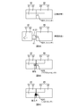
- FIG. 13A is an explanatory diagram of the separation detection unit 52 of the fourth embodiment.
- 13A is an explanatory diagram of a state (proximity state) before the separation detection unit 52 detects the separation between the heating unit 20 and the gripping unit 30.
- FIG. The lower diagram of FIG. 13A is an explanatory diagram of a state (separation state) in which the separation detection unit 52 detects the separation between the heating unit 20 and the grip unit 30.
- the shaft 41 in the figure is a member that connects the heating unit 20 and the gripping unit 30 and guides the relative movement between the heating unit 20 and the gripping unit 30 (see also FIG. 2C).
- one end (rear end, left end in the figure) of the shaft 41 is fixed to the grip portion 30, and the other end of the shaft 41 is heated when the grip portion 30 moves relative to the heating portion 20. It moves inside the unit 20.
- the separation detecting unit 52 of the fourth embodiment detects the separation between the heating unit 20 and the gripping unit 30 by detecting the movement of the shaft 41 when the heating unit 20 and the gripping unit 30 are separated from each other.
- the separation detection unit 52 is configured by a mechanical switch, and the switch (detection unit) is disposed to face the end (detected unit) of the shaft 41 on the heating unit 20 side.
- the separation detection unit 52 detects a separation state (or proximity state) between the heating unit 20 and the gripping unit 30 when the shaft 41 is separated from the switch when the heating unit 20 and the gripping unit 30 are separated from each other.
- FIG. 13B is an explanatory diagram of the separation detection unit 52 according to a modification of the fourth embodiment.
- An end portion of the shaft 41 on the gripping portion 30 side is fixed to the gripping portion 30, and a flange portion 41 ⁇ / b> B protruding outward from the shaft portion 41 ⁇ / b> A of the shaft 41 on the end portion of the shaft 41 on the heating portion 20 side. Is formed.
- the switch (detection unit) constituting the separation detection unit 52 is disposed at a position facing the shaft portion 41A of the shaft 41 in the proximity state, and when the movement amount of the shaft 41 reaches a predetermined amount, It arrange
- the count unit 61A detects the separation state of the heating unit 20 and the gripping unit 30 based on the detection result of the separation detection unit 52 when the heating unit 20 and the gripping unit 30 are separated by a predetermined amount or more. (See S102, S202, S303). In other words, the count value of the number of times of coating removal is not added unless the heating unit 20 and the gripping unit 30 are separated by a predetermined amount or more. For this reason, the counting accuracy of the number of times of coating removal (the accuracy of matching between the number of times of coating removal and the count value) can be improved.
- one end of the shaft 41 is fixed to the grip portion 30, and the switch (detection portion) of the separation detection portion 52 is disposed in the heating portion 20.
- one end of the shaft 41 may be fixed to the gripping unit 30 and a switch constituting the separation detection unit 52 may be disposed in the gripping unit 30.
- the separation detection unit 52 is configured by a switch.
- the separation detection unit 52 is configured by a sensor (such as a magnet sensor or a photo sensor) that detects the holder 7 magnetically or optically. Also good.
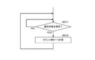
- FIG. 14 is an explanatory diagram of the counting process of the number of coating removals according to the fifth embodiment.
- the counting unit 61A when the counting unit 61A detects the separated state between the heating unit 20 and the gripping unit 30 based on the detection result of the separation detecting unit 52 (YES in S501), the count unit 61A calculates the count value of the number of coating removals. One is added (S502). Even with such processing alone, when the worker separates the heating unit 20 and the gripping unit 30 and the coating on the end of the optical fiber is removed (see FIG. 2C), the count value indicating the number of coating removals is set to 1. Can be increased.
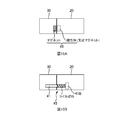
- the coating removal apparatus 10 includes the proximity holding unit 45 that maintains the proximity state in which the heating unit 20 and the gripping unit 30 are brought close to each other.
- FIG. 15A and 15B are explanatory diagrams of a configuration example of the proximity holding unit 45.
- FIG. 15A and 15B are explanatory diagrams of a configuration example of the proximity holding unit 45.
- the proximity holding unit 45 illustrated in FIG. 15A includes a magnet and a magnetic body, the magnet is disposed in the holding unit 30, the magnetic body is disposed in the heating unit 20, and the heating unit 20 uses magnetic force. And the grip portion 30 are kept close to each other.
- a magnet may be arrange
- the separation between the heating unit 20 and the gripping unit may be detected using the magnetic force of the magnet of the proximity holding unit 45.
- the magnet sensor (separation detection unit 52) shown in FIG. 5B may be arranged so as to face the magnet of the gripping unit 30 in FIG. 15A (the magnet constituting the proximity holding unit 45).
- the magnet can be used as the separation detecting unit 52 and the proximity holding unit 45, and the number of components can be reduced.
- the proximity holding part 45 shown in FIG. 15B is configured by a coil spring.
- the coil spring is disposed in a state of being compressed and deformed between the inner wall surface of the heating unit 20 and the flange portion 41 ⁇ / b> B of the shaft 41. Since the coil spring is disposed in a state of being compressed and deformed in advance, the proximity state in which the heating unit 20 and the gripping unit 30 are brought close to each other is maintained by the repulsive force of the coil spring.
- the heating unit 20 and the gripping unit can be used when the coating is not removed. 30 can be prevented from being separated from each other, and the counting accuracy of the coating removal frequency (coincidence accuracy between the coating removal frequency and the count value) can be increased.
Landscapes
- Physics & Mathematics (AREA)
- General Physics & Mathematics (AREA)
- Optics & Photonics (AREA)
- Light Guides In General And Applications Therefor (AREA)
Abstract
Le problème décrit par la présente invention est de suggérer l'échange d'une lame lorsque la lame est émoussée. La solution selon l'invention porte sur un dispositif d'élimination de revêtement comprenant : un dispositif de chauffage comprenant une unité de chauffage servant à chauffer un revêtement de fibre optique et une lame servant à couper le revêtement de fibre optique ; une poignée capable de se déplacer par rapport au dispositif de chauffage tout en saisissant la fibre optique ; et un compteur servant à compter le nombre d'éliminations de revêtement par détection de la séparation entre le dispositif de chauffage et la poignée.
Priority Applications (4)
| Application Number | Priority Date | Filing Date | Title |
|---|---|---|---|
| KR1020187034540A KR20190113524A (ko) | 2017-02-24 | 2017-03-03 | 피복제거장치 |
| EP17872870.5A EP3477349B1 (fr) | 2017-02-24 | 2017-03-03 | Dispositif d'enlèvement de revêtement |
| KR1020177011932A KR102071776B1 (ko) | 2017-02-24 | 2017-03-03 | 피복제거장치 |
| US15/541,298 US10459164B2 (en) | 2017-02-24 | 2017-03-03 | Coating removing device |
Applications Claiming Priority (2)
| Application Number | Priority Date | Filing Date | Title |
|---|---|---|---|
| JP2017033592A JP6154973B1 (ja) | 2017-02-24 | 2017-02-24 | 被覆除去装置 |
| JP2017-033592 | 2017-02-24 |
Publications (1)
| Publication Number | Publication Date |
|---|---|
| WO2018154792A1 true WO2018154792A1 (fr) | 2018-08-30 |
Family
ID=59218565
Family Applications (1)
| Application Number | Title | Priority Date | Filing Date |
|---|---|---|---|
| PCT/JP2017/008491 Ceased WO2018154792A1 (fr) | 2017-02-24 | 2017-03-03 | Dispositif d'enlèvement de revêtement |
Country Status (6)
| Country | Link |
|---|---|
| US (1) | US10459164B2 (fr) |
| EP (1) | EP3477349B1 (fr) |
| JP (1) | JP6154973B1 (fr) |
| KR (2) | KR102071776B1 (fr) |
| CN (2) | CN108508534B (fr) |
| WO (1) | WO2018154792A1 (fr) |
Families Citing this family (10)
| Publication number | Priority date | Publication date | Assignee | Title |
|---|---|---|---|---|
| JP6154973B1 (ja) * | 2017-02-24 | 2017-06-28 | 株式会社フジクラ | 被覆除去装置 |
| CN108321733A (zh) * | 2018-03-10 | 2018-07-24 | 国家电网公司 | 改进型扒电缆专用壁纸刀 |
| WO2021021526A1 (fr) * | 2019-07-26 | 2021-02-04 | Commscope Technologies Llc | Procédés de traitement de câbles à fibres optiques |
| CN114585954B (zh) * | 2019-11-26 | 2025-09-26 | 住友电工光学前沿株式会社 | 包覆层去除器 |
| CN111221077B (zh) * | 2020-02-21 | 2020-11-13 | 深圳市致尚科技股份有限公司 | 一种热剥钳剥纤作业防呆装置 |
| CN111505770B (zh) * | 2020-04-17 | 2022-08-23 | 大族激光科技产业集团股份有限公司 | 剥纤装置及其剥纤方法 |
| JP7247149B2 (ja) | 2020-08-07 | 2023-03-28 | 古河電気工業株式会社 | 被覆除去装置 |
| CN118567030A (zh) | 2023-02-28 | 2024-08-30 | 株式会社藤仓 | 包层除去装置 |
| JP2024148536A (ja) | 2023-04-05 | 2024-10-18 | 住友電工オプティフロンティア株式会社 | 被覆除去器 |
| JP1762909S (ja) | 2023-04-25 | 2024-02-05 | 光ファイバ被覆除去器 |
Citations (5)
| Publication number | Priority date | Publication date | Assignee | Title |
|---|---|---|---|---|
| JPH0190003U (fr) | 1987-12-08 | 1989-06-14 | ||
| JP2002328241A (ja) | 2001-04-26 | 2002-11-15 | Fujikura Ltd | 光ファイバ被覆除去装置 |
| JP2003315561A (ja) * | 2002-04-19 | 2003-11-06 | ▲らい▼徳科技股▲ふん▼有限公司 | 光ファイバ被覆材剥離装置 |
| WO2013024723A1 (fr) * | 2011-08-12 | 2013-02-21 | Seiオプティフロンティア株式会社 | Organe de coupe de fibre optique |
| JP2015184647A (ja) * | 2014-03-26 | 2015-10-22 | Seiオプティフロンティア株式会社 | 被覆除去器及び調整治具 |
Family Cites Families (11)
| Publication number | Priority date | Publication date | Assignee | Title |
|---|---|---|---|---|
| JPS6490003A (en) | 1987-09-30 | 1989-04-05 | Toshiba Corp | Separator |
| JP4383289B2 (ja) * | 2004-08-18 | 2009-12-16 | 古河電気工業株式会社 | 光ファイバ切断装置、光ファイバ融着接続機、光ファイバ切断接続システム、光ファイバ加工管理方法、光ファイバ把持具及び光ファイバ補強装置 |
| KR100582690B1 (ko) | 2005-03-05 | 2006-05-22 | 일신정밀공업(주) | 휴대용 광섬유 처리장치 |
| WO2006112675A1 (fr) | 2005-04-22 | 2006-10-26 | Ilsin Tech Co. Ltd. | Equipement de traitement de fibres optiques portable |
| US7509000B2 (en) | 2006-03-20 | 2009-03-24 | Baker Hughes Incorporated | Downhole optic fiber wet connect system and method |
| CN101916086B (zh) * | 2010-08-20 | 2012-01-11 | 黄超凡 | 剥纤机的数控加工控制方法 |
| CN103477256B (zh) | 2011-03-30 | 2016-06-15 | 株式会社藤仓 | 光纤用被覆层去除工具以及被覆层去除方法 |
| CN102692676B (zh) | 2012-04-27 | 2014-06-11 | 蚌埠吉新通讯机械有限公司 | 一种带状光纤热剥钳 |
| KR101692882B1 (ko) | 2013-03-25 | 2017-01-04 | 가부시키가이샤후지쿠라 | 광섬유 접속부 보강 가열 장치 |
| CN106646740A (zh) * | 2015-07-15 | 2017-05-10 | 泰科电子(上海)有限公司 | 光纤处理设备 |
| JP6154973B1 (ja) | 2017-02-24 | 2017-06-28 | 株式会社フジクラ | 被覆除去装置 |
-
2017
- 2017-02-24 JP JP2017033592A patent/JP6154973B1/ja active Active
- 2017-03-03 WO PCT/JP2017/008491 patent/WO2018154792A1/fr not_active Ceased
- 2017-03-03 KR KR1020177011932A patent/KR102071776B1/ko active Active
- 2017-03-03 KR KR1020187034540A patent/KR20190113524A/ko not_active Withdrawn
- 2017-03-03 US US15/541,298 patent/US10459164B2/en active Active
- 2017-03-03 EP EP17872870.5A patent/EP3477349B1/fr active Active
- 2017-06-08 CN CN201710426656.3A patent/CN108508534B/zh active Active
- 2017-06-08 CN CN201720664119.8U patent/CN207232424U/zh not_active Withdrawn - After Issue
Patent Citations (5)
| Publication number | Priority date | Publication date | Assignee | Title |
|---|---|---|---|---|
| JPH0190003U (fr) | 1987-12-08 | 1989-06-14 | ||
| JP2002328241A (ja) | 2001-04-26 | 2002-11-15 | Fujikura Ltd | 光ファイバ被覆除去装置 |
| JP2003315561A (ja) * | 2002-04-19 | 2003-11-06 | ▲らい▼徳科技股▲ふん▼有限公司 | 光ファイバ被覆材剥離装置 |
| WO2013024723A1 (fr) * | 2011-08-12 | 2013-02-21 | Seiオプティフロンティア株式会社 | Organe de coupe de fibre optique |
| JP2015184647A (ja) * | 2014-03-26 | 2015-10-22 | Seiオプティフロンティア株式会社 | 被覆除去器及び調整治具 |
Also Published As
| Publication number | Publication date |
|---|---|
| CN207232424U (zh) | 2018-04-13 |
| KR102071776B1 (ko) | 2020-01-30 |
| KR20180116109A (ko) | 2018-10-24 |
| CN108508534B (zh) | 2020-06-16 |
| JP2018138970A (ja) | 2018-09-06 |
| US20180267242A1 (en) | 2018-09-20 |
| EP3477349B1 (fr) | 2020-12-09 |
| EP3477349A1 (fr) | 2019-05-01 |
| US10459164B2 (en) | 2019-10-29 |
| KR20190113524A (ko) | 2019-10-08 |
| JP6154973B1 (ja) | 2017-06-28 |
| EP3477349A4 (fr) | 2019-10-23 |
| CN108508534A (zh) | 2018-09-07 |
Similar Documents
| Publication | Publication Date | Title |
|---|---|---|
| JP6154973B1 (ja) | 被覆除去装置 | |
| JP5209126B1 (ja) | 光ファイバ融着接続機 | |
| KR101582485B1 (ko) | 광섬유 융착 접속기 및 이것을 구비하는 광섬유 융착 접속 장치 | |
| JP6267152B2 (ja) | 工具マガジンの工具保持手段の把持力測定手段を備えた工具搬送装置および加工システム | |
| US7412146B2 (en) | Splice protection heater, fusion splicer including the splice protection heater, and fusion splicing method | |
| JP5470661B2 (ja) | 光ファイバホルダ及び光ファイバ融着接続装置 | |
| EP2209026B1 (fr) | Appareil et procédé pour le traitement d'au moins un guide d'ondes optiques | |
| US12222547B2 (en) | Coating removal device | |
| JP6667310B2 (ja) | 補強スリーブの加熱装置および融着接続機 | |
| JP2015184647A (ja) | 被覆除去器及び調整治具 | |
| KR20140003306U (ko) | 신형 유니버설 융착 접속 홀더 | |
| CN108572413B (zh) | 被覆去除装置 | |
| JP2016090943A (ja) | 光ファイバ把持装置 | |
| JP2014182336A (ja) | 被覆除去器 | |
| JP6759944B2 (ja) | 移設検知システムと制御方法 | |
| EP3837574B1 (fr) | Dispositif d'épissage par fusion | |
| JP2018132757A (ja) | 光ファイバ被覆除去装置、融着接続装置、光ファイバ被覆除去システム及び光ファイバ被覆除去方法 | |
| JP4127661B2 (ja) | 光ファイバカッタ及びそれを用いた光ファイバの切断方法 | |
| CN108139614B (zh) | 用于光学设备的电子镜架以及用于操作所述电子镜架的方法 | |
| JP2013187204A (ja) | 部品実装装置 | |
| US12613375B2 (en) | Coating removal tool | |
| JP4196972B2 (ja) | 光ファイバの加熱補強処理装置及び光ファイバ融着接続装置並びに融着接続方法 | |
| JP2014142198A (ja) | 電線処理装置用の金属検出装置及び電線皮剥装置 | |
| JP2015085183A (ja) | プラモデル用ニッパー | |
| CN101212063A (zh) | 在折极耳工序中用于检测电池放置方向的方法 |
Legal Events
| Date | Code | Title | Description |
|---|---|---|---|
| WWE | Wipo information: entry into national phase |
Ref document number: 15541298 Country of ref document: US |
|
| 121 | Ep: the epo has been informed by wipo that ep was designated in this application |
Ref document number: 17872870 Country of ref document: EP Kind code of ref document: A1 |
|
| ENP | Entry into the national phase |
Ref document number: 2017872870 Country of ref document: EP Effective date: 20180627 |
|
| NENP | Non-entry into the national phase |
Ref country code: DE |