WO2013030928A1 - Dispositif de commande de véhicule - Google Patents
Dispositif de commande de véhicule Download PDFInfo
- Publication number
- WO2013030928A1 WO2013030928A1 PCT/JP2011/069460 JP2011069460W WO2013030928A1 WO 2013030928 A1 WO2013030928 A1 WO 2013030928A1 JP 2011069460 W JP2011069460 W JP 2011069460W WO 2013030928 A1 WO2013030928 A1 WO 2013030928A1
- Authority
- WO
- WIPO (PCT)
- Prior art keywords
- mode
- acceleration
- vehicle
- value
- control device
- Prior art date
- Legal status (The legal status is an assumption and is not a legal conclusion. Google has not performed a legal analysis and makes no representation as to the accuracy of the status listed.)
- Ceased
Links
Images


Classifications
-
- B—PERFORMING OPERATIONS; TRANSPORTING
- B60—VEHICLES IN GENERAL
- B60W—CONJOINT CONTROL OF VEHICLE SUB-UNITS OF DIFFERENT TYPE OR DIFFERENT FUNCTION; CONTROL SYSTEMS SPECIALLY ADAPTED FOR HYBRID VEHICLES; ROAD VEHICLE DRIVE CONTROL SYSTEMS FOR PURPOSES NOT RELATED TO THE CONTROL OF A PARTICULAR SUB-UNIT
- B60W30/00—Purposes of road vehicle drive control systems not related to the control of a particular sub-unit, e.g. of systems using conjoint control of vehicle sub-units
- B60W30/18—Propelling the vehicle
- B60W30/182—Selecting between different operative modes, e.g. comfort and performance modes
-
- B—PERFORMING OPERATIONS; TRANSPORTING
- B60—VEHICLES IN GENERAL
- B60W—CONJOINT CONTROL OF VEHICLE SUB-UNITS OF DIFFERENT TYPE OR DIFFERENT FUNCTION; CONTROL SYSTEMS SPECIALLY ADAPTED FOR HYBRID VEHICLES; ROAD VEHICLE DRIVE CONTROL SYSTEMS FOR PURPOSES NOT RELATED TO THE CONTROL OF A PARTICULAR SUB-UNIT
- B60W40/00—Estimation or calculation of non-directly measurable driving parameters for road vehicle drive control systems not related to the control of a particular sub unit, e.g. by using mathematical models
- B60W40/08—Estimation or calculation of non-directly measurable driving parameters for road vehicle drive control systems not related to the control of a particular sub unit, e.g. by using mathematical models related to drivers or passengers
- B60W40/09—Driving style or behaviour
-
- B—PERFORMING OPERATIONS; TRANSPORTING
- B60—VEHICLES IN GENERAL
- B60W—CONJOINT CONTROL OF VEHICLE SUB-UNITS OF DIFFERENT TYPE OR DIFFERENT FUNCTION; CONTROL SYSTEMS SPECIALLY ADAPTED FOR HYBRID VEHICLES; ROAD VEHICLE DRIVE CONTROL SYSTEMS FOR PURPOSES NOT RELATED TO THE CONTROL OF A PARTICULAR SUB-UNIT
- B60W50/00—Details of control systems for road vehicle drive control not related to the control of a particular sub-unit, e.g. process diagnostic or vehicle driver interfaces
- B60W50/0098—Details of control systems ensuring comfort, safety or stability not otherwise provided for
-
- B—PERFORMING OPERATIONS; TRANSPORTING
- B60—VEHICLES IN GENERAL
- B60W—CONJOINT CONTROL OF VEHICLE SUB-UNITS OF DIFFERENT TYPE OR DIFFERENT FUNCTION; CONTROL SYSTEMS SPECIALLY ADAPTED FOR HYBRID VEHICLES; ROAD VEHICLE DRIVE CONTROL SYSTEMS FOR PURPOSES NOT RELATED TO THE CONTROL OF A PARTICULAR SUB-UNIT
- B60W50/00—Details of control systems for road vehicle drive control not related to the control of a particular sub-unit, e.g. process diagnostic or vehicle driver interfaces
- B60W50/08—Interaction between the driver and the control system
- B60W50/10—Interpretation of driver requests or demands
-
- B—PERFORMING OPERATIONS; TRANSPORTING
- B60—VEHICLES IN GENERAL
- B60W—CONJOINT CONTROL OF VEHICLE SUB-UNITS OF DIFFERENT TYPE OR DIFFERENT FUNCTION; CONTROL SYSTEMS SPECIALLY ADAPTED FOR HYBRID VEHICLES; ROAD VEHICLE DRIVE CONTROL SYSTEMS FOR PURPOSES NOT RELATED TO THE CONTROL OF A PARTICULAR SUB-UNIT
- B60W50/00—Details of control systems for road vehicle drive control not related to the control of a particular sub-unit, e.g. process diagnostic or vehicle driver interfaces
- B60W2050/0062—Adapting control system settings
- B60W2050/0075—Automatic parameter input, automatic initialising or calibrating means
- B60W2050/0083—Setting, resetting, calibration
-
- B—PERFORMING OPERATIONS; TRANSPORTING
- B60—VEHICLES IN GENERAL
- B60W—CONJOINT CONTROL OF VEHICLE SUB-UNITS OF DIFFERENT TYPE OR DIFFERENT FUNCTION; CONTROL SYSTEMS SPECIALLY ADAPTED FOR HYBRID VEHICLES; ROAD VEHICLE DRIVE CONTROL SYSTEMS FOR PURPOSES NOT RELATED TO THE CONTROL OF A PARTICULAR SUB-UNIT
- B60W2540/00—Input parameters relating to occupants
- B60W2540/30—Driving style
Definitions
- the present invention relates to an apparatus for performing control to change control characteristics such as driving force and steering so as to conform to a driver's intention (preference or direction).
- the power performance of the vehicle is determined mainly by the relationship between the output control amount such as the throttle opening and the gear ratio with respect to the required drive amount such as the accelerator opening, and the steering characteristics are mainly determined by the steering assist amount for the steering angle and the steering force. Furthermore, the suspension characteristics are mainly determined by the damping force by a shock absorber or the like.
- the vehicle behavior characteristics are almost determined by these performances and characteristics, but the required characteristics of the vehicle are the driver's preference (driving preference), the congestion situation of the road, and the difference between the general road and the exclusive road It depends on such things.
- Japanese Patent Application Laid-Open No. 2008-101742 calculates the degree of agility required by a driver based on vehicle acceleration, accelerator opening, brake pedal force, and the like, that is, the degree of seeking sporty driving, and the degree is large. In this case (specifically, when the counter value is greater than or equal to a threshold value), a device is described that changes the conditions related to gear shifting so that sports running can be easily performed. Therefore, according to the apparatus described in Japanese Patent Application Laid-Open No. 2008-101742, the behavior of the vehicle requested by the driver can be realized without the driver performing a mode selection operation.
- an instruction index corresponding to an index indicating the driver's driving orientation is obtained, and the driving force characteristic, the shift characteristic, the suspension characteristic, etc. are controlled based on the instruction index.
- the device described in Japanese Patent Application Laid-Open No. 2008-101742 is configured such that the condition regarding the shift is changed when the degree of agility calculated as the counter value is equal to or greater than a threshold value. Even if the degree of agility increases, the condition is not changed to sports driving until the threshold is exceeded, and there is a possibility that the vehicle does not perform driving that satisfies the driver's intention.
- the threshold value is set to a large value, the mode is not switched to a mode suitable for sporty driving, or the switching is delayed, so the required power performance cannot be obtained and the driver's intention There is a possibility that the behavior of the vehicle that satisfies the conditions cannot be realized.
- the driving mode is switched to a sporty driving characteristic or mode, and the driving characteristic may be uncomfortable for the driver.
- the present invention has been made paying attention to the above technical problem, and the behavior of the vehicle does not become excessively or frequently agile, and is in accordance with the request when requested by the driver. It is an object of the present invention to provide a vehicle control device that can have agile behavior characteristics.
- the present invention provides a vehicle control device that sets a control characteristic of vehicle behavior to a characteristic according to the driver's driving orientation, and changes in the behavior of the vehicle based on the driver's acceleration / deceleration operation.
- the vehicle control mode is changed to the first mode for generating a small driving force and the second mode for generating a driving force larger than the first mode.
- Switching means for switching between modes is provided, and the threshold value is configured to be a value corresponding to an acceleration limit value at which a human can feel that the acceleration has changed linearly from zero. It is characterized by.
- the acceleration limit value may be an acceleration upper limit value that makes it possible to sense that the acceleration has increased linearly from zero when the vehicle speed is increased, and in the case of deceleration that reduces the vehicle speed, the acceleration limit value. It may be an acceleration lower limit value at which it can be felt that (that is, deceleration) has decreased linearly from zero.
- the vehicle control device of the present invention can be configured to change the control characteristics so that the behavior of the vehicle becomes agile as the value of the index increases.
- the index includes a square root of the sum of the square of the longitudinal acceleration and the square of the lateral acceleration of the vehicle, and the threshold value is 3.5 m / s 2 or more and 4.5 m / s 2 or less. Can be a value.
- the switching means switches from one of the first mode and the second mode to the other from the time when the value of the index changes across the threshold value.
- the change between the first mode and the second mode can be completed within a predetermined time that can be perceived by a human.
- the predetermined time may be a time determined based on a human information processing cycle, and more specifically, a time of 500 milliseconds or less.
- the first driving force with a small driving force is obtained.
- the mode is switched to the second mode having a large driving force, or when the index falls below the threshold value, the mode is switched from the second mode to the first mode.
- the threshold value is a value that sets a control characteristic that generates an acceleration limit value that allows a human to feel that the acceleration changes linearly from zero. Changes, the acceleration continuously changes according to the change of the index, and after reaching the acceleration limit value, the mode changes to reset the zero point that human feels linear, and then the acceleration becomes more continuous To change. Accordingly, it is possible to prevent or suppress the acceleration from being insufficient or excessively accelerating against the driver's intention, thereby improving the so-called drivability.
- the time required for the switching is within a time set in advance as a time that can be perceived by humans. More specifically, for normal human operations and perceptions and judgments of the operations. Because it is within the time determined based on the so-called information processing cycle time required, the change in acceleration becomes more continuous, and as a result, the difference between the continuity of operation and the continuity of change in acceleration or vehicle behavior. Can be avoided or reduced to improve drivability.
- a vehicle to which the control device of the present invention can be applied is a vehicle that accelerates / decelerates and turns by operating a predetermined operating device by a driver.
- Typical examples thereof include an internal combustion engine and a motor as a driving force source. It is a car.
- An example of this is shown in a block diagram in FIG.
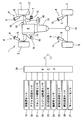
- the vehicle 1 shown here is a vehicle provided with four wheels, that is, left and right front wheels 2 as steering wheels and left and right rear wheels 3 as drive wheels, and each of these four wheels 2 and 3 is a suspension device 4.
- a vehicle body (not shown) is supported via
- the suspension device 4 is the same as that conventionally known, and is mainly composed of a spring and a shock absorber (damper).
- the shock absorber 5 is configured to generate a buffering action by using the flow resistance of a fluid such as gas or liquid, and is configured to be able to change the flow resistance to an increase or decrease by an actuator such as a motor 6. That is, when the flow resistance is increased, the vehicle body is unlikely to sink, and the vehicle feels so hard that the comfort of the vehicle is reduced and the sporty feeling is increased.
- the vehicle height can be adjusted (height control) by supplying and discharging pressurized gas to and from these shock absorbers 5.
- the front and rear wheels 2 and 3 are each provided with a brake device (not shown).
- each brake device When the brake pedal 7 disposed in the driver's seat is depressed, each brake device operates to apply braking force to the front and rear wheels 2 and 3. Is configured to give.
- the driving force source of the vehicle 1 is a driving force source having a conventionally known configuration, such as an internal combustion engine, a motor, or a combination thereof.
- FIG. 6 shows a vehicle equipped with an internal combustion engine (engine) 8, and an intake pipe 9 of the engine 8 is provided with a throttle valve 10 for controlling the intake air amount.
- the throttle valve 10 is configured as an electronic throttle valve, and is configured to be opened and closed by an electrically controlled actuator 11 such as a motor, and the opening degree is adjusted.
- the actuator 11 operates in accordance with the depression amount of the accelerator pedal 12 arranged at the driver's seat, that is, the accelerator opening, and adjusts the throttle valve 10 to a predetermined opening (throttle opening).
- the relationship between the accelerator opening, which is the amount of depression of the accelerator pedal 12, and the opening of the throttle valve 10 can be set as appropriate. The closer the relationship between the two, the stronger the so-called direct feeling and the more It feels good.
- the control characteristic is set so that the throttle opening becomes relatively small with respect to the accelerator opening, the behavior or acceleration characteristic of the vehicle becomes a so-called mild feeling.
- a current controller such as an inverter or a converter is provided in place of the throttle valve 10 to adjust the current according to the accelerator opening, and the current value relative to the accelerator opening.
- the relationship, that is, the behavior characteristic or the acceleration characteristic is appropriately changed.
- the transmission 13 is connected to the output side of the engine 8.
- the transmission 13 is configured to appropriately change the ratio between the input rotational speed and the output rotational speed, that is, the gear ratio.
- a conventionally known stepped automatic transmission or belt-type continuously variable transmission is used.
- a toroidal continuously variable transmission is used. Therefore, the transmission 13 includes an actuator (not shown), and is configured to change the gear ratio stepwise (stepwise) or continuously by appropriately controlling the actuator.
- the speed change control is basically performed so as to set a speed change ratio at which fuel efficiency is good.
- the target output is calculated based on the state, the target engine speed is obtained from the target output and the optimum fuel consumption line, and the shift control is executed so that the target engine speed is obtained.
- a transmission mechanism such as a torque converter with a lock-up clutch can be provided between the engine 8 and the transmission 13 as necessary.
- the output shaft of the transmission 13 is connected to the rear wheel 3 via a differential gear 14 that is a final reduction gear.
- a steering linkage 17 is provided for transmitting the rotational operation of the steering wheel 16 to the left and right front wheels 2, and the assist assists the steering angle or steering force of the steering wheel 16.
- a mechanism 18 is provided.
- the assist mechanism 18 is configured to be able to adjust the assist amount by an actuator (not shown). Therefore, by reducing the assist amount, the steering angle and the actual turning angle of the front wheels 2 become close to a one-to-one relationship. The so-called direct feeling of steering is increased, and the behavior characteristic of the vehicle is so-called sporty.
- the vehicle 1 described above includes an anti-lock brake system (ABS), a traction control system, and a vehicle that integrates and controls these systems as a system for stabilizing behavior or posture.
- a stability control system (VSC) or the like is provided. These systems are conventionally known, and reduce the braking force applied to the wheels 2 and 3 based on the deviation between the vehicle body speed and the wheel speed, or apply the braking force. By controlling the engine torque, it is configured to prevent or suppress the locking and slipping of the wheels 2 and 3 to stabilize the behavior of the vehicle.
- a navigation system that can obtain data (ie, driving environment) related to the driving path and planned driving path, and driving modes such as a sports mode (sport D), a normal mode (normal D), and a low fuel consumption mode (eco mode).
- driving modes such as a sports mode (sport D), a normal mode (normal D), and a low fuel consumption mode (eco mode).
- sports mode sports D
- normal D normal D
- eco mode low fuel consumption mode
- a wheel speed sensor 19 that detects the rotational speeds of the front and rear wheels 2 and 3, an accelerator opening sensor 20, a throttle opening sensor 21, an engine speed sensor 22, and an output speed of the transmission 13 are detected.
- the acceleration sensors Gx and Gy can be used in common with acceleration sensors used in vehicle behavior control such as the anti-lock brake system (ABS) and the vehicle stability control system (VSC) described above. In a vehicle equipped with a bag, it can be shared with an acceleration sensor provided for the deployment control.
- These sensors 19 to 27 are configured to transmit a detection signal (data) to an electronic control unit (ECU) 28, and the electronic control unit 28 stores those data and data and programs stored in advance. The calculation result is output to each of the above-described systems or their actuators as a control command signal.
- the “mode” in the present invention is a control mode of the behavior of the vehicle, and is a normal mode in which each characteristic such as fuel consumption, quietness, and acceleration is at a certain level. (Normal mode), a sport mode in which agility, acceleration, or power performance is superior to the normal mode, an economy mode (eco mode) in which fuel efficiency is excellent, and the like.
- Normal mode a sport mode in which agility, acceleration, or power performance is superior to the normal mode
- an economy mode eco mode in which fuel efficiency is excellent, and the like.
- the relationship between the throttle opening (or power source output) or the relationship between the engine speed (ie, the output characteristics), the vehicle speed and the accelerator opening is set so that the designed behavior is realized.
- Ratio relationship (ie shift characteristics), relation of steering assist amount to vehicle speed and steering angle (ie steering characteristics), support height of vehicle body (ie vehicle height) by suspension mechanism and shock absorber damping force relation (ie suspension characteristics) ) Characteristics are set according to each mode. More specifically, in the sport mode, so as to realize an agile behavior, the output is large, the gear ratio is relatively large to increase the engine speed, and the steering assist amount is reduced to reduce the amount of steering assist. In addition to enhancing the feeling, the damping force of the shock absorber is increased to reduce the sinking of the vehicle body, and further, the vehicle height is controlled to be lowered.
- the throttle opening and gear ratio control characteristics are set so that the fuel efficiency is good, the suspension characteristics are set so that the vibration of the vehicle body is reduced, and the steering assist amount is further reduced. Will be increased.
- each characteristic is set to a characteristic that realizes an intermediate behavior between the sport mode and the eco mode.
- the vehicle control device not only performs the correction of the control characteristics in a state where any mode is set according to the index obtained based on the behavior of the vehicle, but also switches the mode. It is configured to perform according to the index.
- the index that can be adopted in the present invention is preferably one that is considered to represent the driver's intention or driving orientation (preference or orientation).
- the vehicle acceleration or a predetermined value obtained by correcting the vehicle acceleration is preferable. It may be a calculated value, an accelerator opening, its operating speed, a predetermined calculated value obtained from these values, a steering angle, a steering speed, or a predetermined calculated value obtained from these values.
- One example thereof is the instruction SPI described in the above-mentioned International Publication No. 2011/021634.
- the instruction SPI will be described as follows.
- the instruction SPI is an index obtained based on a so-called combined acceleration obtained by combining the longitudinal acceleration and the lateral acceleration of the vehicle, and the combined acceleration is calculated by the following formula, and the value is “the sportiness degree at each moment”. In this sense, it is an instantaneous SPI (instantaneous sporty index).
- Instantaneous SPI (Gx 2 + Gy 2 ) 1/2
- Gx is the longitudinal acceleration
- Gy is the lateral acceleration.
- the longitudinal acceleration Gx used in the above-described arithmetic expression it is preferable to use a normalized one for at least one of the acceleration on the acceleration side or the acceleration on the deceleration side (that is, deceleration). That is, in a general vehicle, the acceleration on the deceleration side is larger than the acceleration on the acceleration side, but the difference is hardly perceived or recognized by the driver. Are recognized to occur almost equally.
- the normalization process is a process for correcting such a difference between the actual value and the driver's feeling. For the longitudinal acceleration Gx, the acceleration side acceleration is increased or the deceleration side acceleration is increased. It is a process to make it smaller.
- the degree of reflection on the behavior characteristics for accelerations with different directions in other words, the degree of change in behavior characteristics based on the acceleration in one direction is different from the degree of change in behavior characteristics based on the acceleration in the other direction. It is preferable to configure so that the
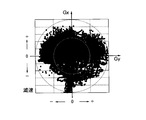
- FIG. 7 shows an example in which the sensor value of the lateral acceleration Gy and the longitudinal acceleration Gy subjected to the above normalization process are plotted on the tire friction circle. This is an example of running on a test course simulating a general road, and the lateral acceleration Gy does not increase frequently when decelerating significantly, but it is a general tendency that some lateral acceleration Gy occurs during deceleration. It can be seen that.
- the instruction SPI is obtained from the above instantaneous SPI.
- This instruction SPI is an index used for control to change the behavior characteristic, and increases immediately with respect to the increase in the instantaneous SPI that is the basis of the calculation, and decreases with a delay with respect to the decrease in the instantaneous SPI. It is a composed indicator.
- the instruction SPI is reduced due to the establishment of a predetermined condition.
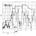
- FIG. 8 shows a change in the instruction SPI obtained based on an instantaneous SPI that is caused by acceleration (braking G) during braking.
- the instantaneous SPI is indicated by the value plotted in FIG.
- the instruction SPI is set to the maximum value of the instantaneous SPI and until the predetermined condition is satisfied, the previous SPI is set. Configured to maintain the value. That is, the instruction SPI is configured as an index that changes rapidly on the increase side and relatively slowly changes on the decrease side.
- the instruction SPI increases stepwise.
- the instruction SPI is lowered because the condition for reduction is satisfied.
- the condition for lowering the instruction SPI in this way is that a state where it is considered undesirable to hold the instruction SPI at a previously large value is established, and in the present invention, it is established due to the passage of time. It is configured as follows.
- Such an instruction SPI lowering start condition (that is, an instruction SPI changing condition) can be a duration of a state in which the instantaneous SPI is lower than the instruction SPI, and the actual running state can be more accurately changed to the instruction SPI.
- the instruction SPI decrease start condition that the time integral value (or cumulative value) of the deviation between the instruction SPI and the instantaneous SPI reaches a predetermined threshold value.
- the threshold value may be set as appropriate through experiments and simulations. If the latter integral value is used, the instruction SPI is reduced in consideration of the deviation and time between the instruction SPI and the instantaneous SPI, so that the behavior characteristics change more accurately reflecting the actual running state or behavior. Control becomes possible.
- the holding time of the instruction SPI until reaching the time point t2 is longer than the holding time of the instruction SPI until reaching the time point t3. This is because it is configured to perform. That is, the instruction SPI is increased and held at a predetermined value at the end of the time period T1 described above, and then the instantaneous SPI is increased and held at time t1 before the above-described decrease start condition is satisfied.
- the deviation from the instruction SPI is equal to or less than a predetermined value.
- the predetermined value may be set as appropriate by conducting experiments or simulations or taking into account the instantaneous SPI calculation error.
- the fact that the instantaneous SPI is close to the instruction SPI being held means that the acceleration / deceleration state, the turning state, or the state that caused the instantaneous SPI that is the basis of the held instruction SPI has been reached. It means that That is, even if a certain amount of time has elapsed from when the instruction SPI is increased to the value held, the instantaneous SPI is instructed because the traveling state is approximate to the traveling state before the time has elapsed. Even if a state below the SPI occurs, the establishment of the above-described decrease start condition is delayed and the instruction SPI is held at the previous value.
- the control or processing for the delay is performed by resetting the accumulated value (cumulative value) of the elapsed time or the integrated value of the deviation, and restarting the accumulated time or integrating the deviation,
- the integration value may be reduced by a predetermined amount, or the integration or integration may be interrupted for a predetermined time.
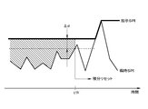
- FIG. 9 is a schematic diagram for explaining the above-described deviation integration and resetting.
- the hatched area in FIG. 9 corresponds to the integral value.
- the integration value is reset at time t11 when the difference between the instantaneous SPI and the instruction SPI becomes equal to or less than the predetermined value ⁇ d, and the integration of the deviation is started again. Therefore, even if the duration during which the instruction SPI is held at a predetermined value becomes longer, the lowering start condition is not satisfied, so the instruction SPI is maintained at the previous value. Then, after the integration is resumed, when the instantaneous SPI becomes a value larger than the immediately preceding instruction SPI, the instruction SPI is updated to a large value corresponding to the instantaneous SPI and held.
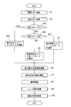
- FIG. 1 is a flowchart for explaining an example in which the present invention is applied to a control device for a vehicle configured to be able to select a normal mode and a sports mode, and based on the running state at that time, Alternatively, the instantaneous SPI is calculated based on the detected value of the acceleration sensor (step S1), and the instruction SPI is calculated based on the instantaneous SPI (step S2). The method for obtaining these instantaneous SPI and instruction SPI is as described above. Next, it is determined whether or not the obtained instruction SPI is smaller than a predetermined threshold value X (step S3).
- the threshold value X is a reference value for selecting a mode, and is set as described below in the present invention.
- the instruction SPI is obtained based on the acceleration and reflects the driving orientation, and is substantially the absolute value of the combined acceleration. Therefore, if the instruction SPI is a large value, Each characteristic such as an output characteristic and a shift characteristic is set so that the behavior becomes more agile. For example, the low speed gear ratio (relatively large gear ratio) is set so that the throttle opening or output torque with respect to the accelerator opening increases and the driving force increases. That is, each characteristic is changed so as to be suitable for sporty running. As described above, when the instruction SPI increases, the acceleration of the vehicle increases in accordance with the drive request amount such as the accelerator opening.
- the control to increase the acceleration or generate a large driving force is basically the control to increase the minimum number of revolutions in a vehicle equipped with an engine, but the change in acceleration according to the driver's request is Although it is felt as a linear change for the driver within a predetermined range from zero, it is difficult to get a sense of how much the acceleration is beyond that range, and the linear change from zero is experienced. It becomes difficult to do. In other words, there is a possibility that the acceleration operation deviates from the change in acceleration that is experienced, resulting in a sense of incongruity. Further, if the vehicle speed increases, so-called marginal acceleration until the maximum acceleration that can be generated is reduced, and even if the accelerator operation is performed, the acceleration is difficult to increase.
- FIG. 2 shows a measurement result in which the acceleration of the vehicle is gradually increased from “0” as a stimulus amount, and the acceleration perceived by a person on the vehicle is taken as a sense amount.
- the data obtained for a plurality of passengers are indicated by different symbols in FIG. 2, and as the acceleration increases, the correspondence between the sensory amount and the stimulus amount becomes dilute, and the acceleration is 4.5 m / s 2. Beyond this, the relationship between acceleration and the acceleration experienced by most passengers became unclear. Therefore, when the instruction SPI requires acceleration exceeding 4.5 m / s 2 , even if the vehicle performs acceleration according to the request, the change in acceleration cannot be experienced, and the intended running state It cannot be determined whether or not.
- the threshold value X is a reference value for selecting or switching between the normal mode and the sport mode, as will be described later, for determining the magnitude of the value of the instruction SPI.
- the instruction SPI is obtained based on the combined acceleration, and the combined acceleration becomes a large value if the longitudinal acceleration or the lateral acceleration increases even if it is a temporary steering operation, accelerator operation or braking operation. Become. Therefore, even if the driver does not intend to be agile (ie, sport driving), if he / she steers greatly, depresses the accelerator pedal, or operates the brakes to avoid carelessness or avoiding obstacles The value of the instruction SPI increases.
- the threshold value X is preferably a value in a predetermined range with 4.5 m / s 2 as an upper limit.
- the lower limit of the determination is a value that does not frequently cause automatic switching to the sport mode, and can be set based on experiments, simulations, and the like.
- “3.5 m / s 2 ” is preferably set as the lower limit value of the threshold value X from the results of experiments and simulations. Therefore, a value determined by design in “3.5 m / s 2 to 4.5 m / s 2 ” corresponds to the acceleration upper limit value in the present invention.
- the normal mode is selected as the basic characteristic (step S4).
- the sport mode is selected as the basic characteristic (step S5). That is, when the instruction SPI increases and becomes equal to or greater than the threshold value X, the sport mode is selected, and when the instruction SPI decreases from that state and becomes smaller than the threshold value X, the normal mode is restored.
- the normal mode is a control characteristic that assumes behavior at the planning or design stage of the vehicle.
- the sport mode is more agile than the normal mode. This is a control characteristic. When comparing the normal mode in vehicles such as so-called family cars and luxury cars with the normal mode in vehicles called so-called sports cars and GT cars, the behavior of the vehicle is relative in the normal mode of the latter vehicle. Be agile.
- control characteristics included in each mode include the output control characteristics, shift characteristics, steering characteristics, suspension characteristics, etc. of the engine 8, and the output characteristics will be described.
- the accelerator opening and the throttle opening or The relationship with the fuel injection amount is set to be close to a proportional relationship represented by a straight line or a line close thereto, and in the normal mode, the relationship between the accelerator opening and the throttle opening or the fuel injection amount is two. It is set to the relationship expressed by the next curve. That is, in the sport mode, the engine output changes sensitively with respect to the change in the accelerator opening, whereas in the normal mode, the change in the engine output with respect to the change in the accelerator opening is small when the accelerator opening is small. Become.
- the steering assist amount is set to be small so that a so-called direct feeling with respect to steering becomes remarkable, and in the normal mode, the steering assist amount is set to be larger than that in the sport mode. Then, the suspension characteristics will be explained.
- the damping force of the shock absorber is set to be large and the vehicle height is controlled to suppress the rolling and squatting of the vehicle body, and the normal mode is compared with this. Then, in order to improve the vibration absorption, the damping force of the shock absorber is set to be small and the vehicle height is controlled to be high.
- Each of these control characteristics is prepared in advance as a normal mode and a sport mode in advance, and when one of the modes is selected, each control characteristic is a characteristic in the selected mode. Can be switched to. Specifically, the map used for control is changed, the control gain is changed, the detected data or the control data calculated from the data is corrected, or the coefficient for the correction is changed.
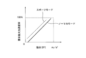
- the required maximum acceleration rate is calculated (step S6).
- the required maximum acceleration rate defines the marginal driving force.
- the required maximum acceleration rate of 100% is a state that enables the maximum acceleration that can be generated by the vehicle. Is to set the gear ratio that maximizes the engine speed or the largest gear ratio (the gear ratio on the lowest vehicle speed side).
- the required maximum acceleration rate of 50% is the maximum that the vehicle can generate. This is a state in which an acceleration that is half of the acceleration is enabled, and an intermediate gear ratio is set for the transmission 13.
- the required maximum acceleration rate increases as the instruction SPI increases.
- step S7 a calculation for correcting the basic characteristics is executed (step S7).
- the correction of the basic characteristics is control for changing the control characteristics in accordance with the instruction SPI, the drive request amount, and the like within the range of each of the normal mode and the sports mode. For example, shift control will be described.
- the gear ratio or gear stage obtained based on the map used in each mode is corrected to a larger gear ratio or a lower gear ratio as the instruction SPI or accelerator opening is larger. This may correct the gear ratio or the gear stage itself, but may correct data for obtaining the gear ratio or the gear stage.
- FIG. 4 shows the contents of such correction in terms of the engine speed.
- FIG. 4A shows an example in the sport mode, and the engine speed is corrected to increase as the instruction SPI increases.
- FIG. 4B is an example of the normal mode, and control is performed so that the engine speed increases as the accelerator opening increases.
- the control amount obtained based on the basic characteristics in the normal mode, the control amount obtained based on the basic characteristics in the sport mode, and the control amounts obtained by correcting the basic characteristics are Will exist. Any of these control amounts is limited by some limiting factor, and may be a small value (a value that reduces the agility of the behavior) with respect to other control amounts. Therefore, in the control example shown in FIG. 1, arbitration control is executed (step S8).
- the arbitration control is a control amount obtained based on the basic characteristics in the normal mode, a control amount obtained based on the basic characteristics in the sport mode, and a control amount obtained by correcting each basic characteristic. And the control amount that makes the behavior of the vehicle more agile is selected from among these control amounts.
- step S8 is not necessarily indispensable in the present invention and may not be executed.
- the gear ratio or the gear position is controlled according to the basic characteristics in each mode, or controlled according to the characteristics obtained by correcting the basic characteristics.
- the chassis characteristic is calculated in parallel with or after the control at the gear ratio or the shift speed (step S9), and the driving force characteristic is calculated (step S10).
- These characteristics change the control characteristics of the throttle valve 10 described above, the speed change characteristics of the transmission 13, the damping characteristics of the suspension device 4 by the shock absorber 5, the assist characteristics of the assist mechanism 18 and the like by the actuators respectively provided. Is set appropriately.
- the general tendency of the change in the control characteristic is a change to a characteristic that enables so-called sporty driving in which the behavior of the vehicle is more agile as the instruction SPI is larger.
- a characteristic that enables agile acceleration with a large driving force a characteristic that the vehicle body is firmly supported and that sinks and lifts is relatively small, and a characteristic that has a so-called direct feeling of steering with a small amount of assist for steering It is.
- the basic characteristics in the normal mode and the basic characteristics in the sport mode are set in advance, and according to the respective basic characteristics, the steering assist amount, the damping force of the shock absorber, or the accelerator opening
- the throttle opening is controlled, and the control amount is corrected to be large or small in accordance with the instruction SPI within the range of each basic characteristic.
- the above-described threshold value X is provided to select the mode, and therefore the instruction SPI changes across the threshold value X. If you do, the mode is switched.
- the threshold value X is a predetermined value within the range of 3.5 m / s 2 to 4.5 m / s 2 . That is, it is a value corresponding to the maximum value that allows a human to recognize that the acceleration changes linearly from “0”. Therefore, for example, when the absolute value of the resultant acceleration increases while driving in the normal mode and the value exceeds the threshold value X, the normal mode is switched to the sports mode, and the acceleration according to the basic characteristics in the sports mode. Each control is executed.
- linear change in acceleration means that the tendency of change is constant or linear, and therefore “cannot feel linear change in acceleration” Even if you can feel that the acceleration is changing, the change is discontinuous or the tendency of the change is different from the previous one.
- the acceleration does not change temporarily and changes again after switching the mode. Therefore, the change in acceleration after switching the mode becomes a change from “0”, and the human changes the acceleration. After resetting the zero point that feels linear, you can experience the linear change. However, if it takes a long time to switch the mode, the driver recognizes that the change in acceleration is interrupted, and such a stagnation in the change in acceleration may be uncomfortable. In order not to cause such a sense of incongruity, the mode switching is controlled to be completed within a predetermined time.
- the predetermined time required for the mode switching is set as described below.
- the “human information processing model” when a person with average operation ability and perception ability performs some operation according to his / her own will, the completion of the operation from the occurrence of the intention of the operation is performed. It takes an actual operation time for moving a finger or hand, a time for perceiving that the operation has been performed, and a time for completing the operation or recognizing the result until the recognition. The total of these times is about 250 milliseconds to 500 milliseconds.
- the mode switching is completed within 500 milliseconds, preferably within 250 milliseconds, at the latest from the time when the instruction SPI reaches the threshold value X described above.
- This predetermined time includes a control delay time in the control system.
- the sport mode described above is a mode in which each control characteristic is set so that the behavior of the vehicle becomes agile, and therefore the fuel consumption is somewhat inferior to that in the case of controlling in the normal mode. Therefore, it is also possible to set a mode that emphasizes fuel consumption rather than behavioral agility, which is a mode that can be referred to as an eco mode (economy mode), and mainly maintains the engine speed at a speed that provides optimum fuel efficiency. It is a mode to do.
- chassis characteristics and driving force characteristics are set so as to match the engine speed and the driving force associated therewith.
- FIG. 5 is a flowchart for explaining a control example in which the eco mode can also be selected.
- a lower limit threshold value X1 and an upper limit threshold value X2 for the instruction SPI are provided.
- the sports mode, the normal mode, and the eco mode are selected based on the comparison result between the instruction SPI and the threshold values X1 and X2.
- Step S1 and step S2 the calculation of the instantaneous SPI and the instruction SPI (step S1 and step S2) is performed in the same manner as the control example shown in FIG. 1, and it is determined whether or not the instruction SPI is smaller than the lower limit threshold value X1.
- This lower limit threshold value X1 is a parameter such as the minimum value of acceleration at which a person on the vehicle can feel a change from zero in a normal driving posture, or the accelerator opening corresponding to the minimum value. When traveling in an urban area, the speed is 1.0 m / s 2 to 1.5 m / s 2 . Therefore, the lower limit threshold value X1 may be set as a different value for each vehicle depending on the structure of the vehicle and the so-called vehicle case.
- step S32 it is determined whether the instruction SPI is smaller than the upper threshold X2 (> X1) (step S32). ).
- This upper limit threshold value X2 is the maximum value of acceleration at which a person with an average sensation on the vehicle can feel that the acceleration has changed linearly from almost zero in a normal driving posture, or As a parameter such as the accelerator opening corresponding to the maximum value is 4.5 m / s 2 from 3.5 m / s 2 regardless of the vehicle speed.
- This upper limit threshold value X2 is determined in advance by experiments or the like. Therefore, the upper limit threshold value X2 may be set as a different value for each vehicle depending on the structure of the vehicle or what is called a vehicle case.
- step S4 If the instruction SPI is smaller than the upper limit threshold value X2 and an affirmative determination is made in step S32, the normal mode is selected as the basic characteristic (step S4), and conversely, the instruction SPI is greater than or equal to the upper limit threshold value X2. If the determination is negative in step S32, the sport mode is selected as the basic characteristic (step S5).
- the control in step S4 and step S5 is the same control as step S4 and step S5 shown in FIG.
- step S33 the eco mode is selected as the basic characteristic (step S33). Since this eco mode is a mode that gives priority to improving fuel efficiency, in this eco mode, the driving force is small or the change is gradual, so a small gear ratio is frequently used. Also, the damping force of the shock absorber is small, the vehicle height is controlled to be high, and the steering assist amount is larger than in other modes. Such control characteristics can be prepared in advance. Then, after any mode is selected or switched to any one of the above steps S4, S5 and S33, the control of steps S6 to S10 is executed. Note that the control in steps S6 to S10 is the same as the control shown in FIG.
- the modes are more diversified. Therefore, it is possible to automatically set the driving performance suitable for each driver and the driving performance suitable for each driving environment. In addition, the fuel efficiency can be improved.
Landscapes
- Engineering & Computer Science (AREA)
- Automation & Control Theory (AREA)
- Transportation (AREA)
- Mechanical Engineering (AREA)
- Human Computer Interaction (AREA)
- Physics & Mathematics (AREA)
- Mathematical Physics (AREA)
- Control Of Driving Devices And Active Controlling Of Vehicle (AREA)
- Vehicle Body Suspensions (AREA)
Abstract
Priority Applications (5)
| Application Number | Priority Date | Filing Date | Title |
|---|---|---|---|
| US14/240,892 US9656675B2 (en) | 2011-08-29 | 2011-08-29 | Vehicle control system |
| JP2013530911A JP5696788B2 (ja) | 2011-08-29 | 2011-08-29 | 車両制御装置 |
| CN201180073195.7A CN103764471B (zh) | 2011-08-29 | 2011-08-29 | 车辆控制装置 |
| PCT/JP2011/069460 WO2013030928A1 (fr) | 2011-08-29 | 2011-08-29 | Dispositif de commande de véhicule |
| EP11871797.4A EP2752346B1 (fr) | 2011-08-29 | 2011-08-29 | Dispositif de commande de véhicule |
Applications Claiming Priority (1)
| Application Number | Priority Date | Filing Date | Title |
|---|---|---|---|
| PCT/JP2011/069460 WO2013030928A1 (fr) | 2011-08-29 | 2011-08-29 | Dispositif de commande de véhicule |
Publications (1)
| Publication Number | Publication Date |
|---|---|
| WO2013030928A1 true WO2013030928A1 (fr) | 2013-03-07 |
Family
ID=47755482
Family Applications (1)
| Application Number | Title | Priority Date | Filing Date |
|---|---|---|---|
| PCT/JP2011/069460 Ceased WO2013030928A1 (fr) | 2011-08-29 | 2011-08-29 | Dispositif de commande de véhicule |
Country Status (5)
| Country | Link |
|---|---|
| US (1) | US9656675B2 (fr) |
| EP (1) | EP2752346B1 (fr) |
| JP (1) | JP5696788B2 (fr) |
| CN (1) | CN103764471B (fr) |
| WO (1) | WO2013030928A1 (fr) |
Cited By (1)
| Publication number | Priority date | Publication date | Assignee | Title |
|---|---|---|---|---|
| JP2019203886A (ja) * | 2018-05-17 | 2019-11-28 | 花王株式会社 | 触感評価方法および触感計測装置 |
Families Citing this family (12)
| Publication number | Priority date | Publication date | Assignee | Title |
|---|---|---|---|---|
| KR102321242B1 (ko) | 2014-10-16 | 2021-11-02 | 얀마 파워 테크놀로지 가부시키가이샤 | 작업 차량 |
| US10137897B2 (en) | 2016-06-13 | 2018-11-27 | Toyota Motor Engineering & Manufacturing North America, Inc. | Systems and methodologies for modifying a vehicle operating profile |
| JP2018001901A (ja) * | 2016-06-30 | 2018-01-11 | アイシン精機株式会社 | 走行支援装置 |
| JP7006326B2 (ja) * | 2018-02-01 | 2022-01-24 | トヨタ自動車株式会社 | 自動運転システム |
| US11358521B2 (en) * | 2018-08-08 | 2022-06-14 | Uatc, Llc | Vehicle wheel units |
| US10668930B1 (en) | 2019-02-04 | 2020-06-02 | State Farm Mutual Automobile Insurance Company | Determining acceptable driving behavior based on vehicle specific characteristics |
| JP7581899B2 (ja) * | 2021-01-19 | 2024-11-13 | マツダ株式会社 | 制御装置および制御システム |
| CN115179950B (zh) * | 2021-03-26 | 2023-09-08 | 广州汽车集团股份有限公司 | 基于驾驶行为的驾驶模式调整方法和车辆 |
| CN115465277A (zh) * | 2021-06-10 | 2022-12-13 | 康明斯有限公司 | 建议或调整车辆运行模式的系统和方法 |
| CN113715824B (zh) * | 2021-09-29 | 2024-05-17 | 潍柴动力股份有限公司 | 一种发动机经济模式控制方法和车辆 |
| US12233881B2 (en) * | 2022-02-07 | 2025-02-25 | Ford Global Technologies, Llc | Methods and systems for vehicle operation based on the determined driver category |
| CN114919595B (zh) * | 2022-06-13 | 2024-07-02 | 阿维塔科技(重庆)有限公司 | 一种驾驶模式控制方法、装置及汽车 |
Citations (7)
| Publication number | Priority date | Publication date | Assignee | Title |
|---|---|---|---|---|
| JPH042518A (ja) * | 1990-04-18 | 1992-01-07 | Nissan Motor Co Ltd | 制駆動力と輪荷重配分の総合制御装置 |
| JP2008101742A (ja) | 2006-10-20 | 2008-05-01 | Toyota Motor Corp | 車両の制御装置、制御方法、その制御方法をコンピュータで実現するプログラムおよびそのプログラムを記録した記録媒体 |
| JP2008254600A (ja) * | 2007-04-05 | 2008-10-23 | Toyota Motor Corp | 車両制御装置 |
| JP2009530166A (ja) * | 2006-03-22 | 2009-08-27 | ジーエム グローバル テクノロジー オペレーションズ,インク. | 運転スタイル感応性車両サブシステム制御方法及び装置 |
| JP2010061330A (ja) * | 2008-09-03 | 2010-03-18 | Hitachi Ltd | ドライバ運転技能支援装置及びドライバ運転技能支援方法 |
| JP2010285139A (ja) * | 2009-05-15 | 2010-12-24 | Toyota Motor Corp | 車両制御装置 |
| WO2011021634A1 (fr) | 2009-08-18 | 2011-02-24 | トヨタ自動車株式会社 | Dispositif de contrôle de véhicule |
Family Cites Families (8)
| Publication number | Priority date | Publication date | Assignee | Title |
|---|---|---|---|---|
| DE3922051A1 (de) * | 1989-07-05 | 1991-01-24 | Porsche Ag | Verfahren und vorrichtung zur steuerung eines selbsttaetig schaltenden getriebes |
| GB2245873B (en) * | 1990-04-18 | 1994-03-16 | Nissan Motor | Control system for optimizing operation of vehicle performance/safety enhancing systems |
| JP4304038B2 (ja) | 2003-10-03 | 2009-07-29 | 本田技研工業株式会社 | 無段変速機制御装置 |
| WO2006119378A2 (fr) * | 2005-05-03 | 2006-11-09 | Pinpoint Tracking Solutions, Llc | Systeme et procede d'interfaçage avec un reseau de commande d'un vehicule |
| WO2007107361A1 (fr) * | 2006-03-22 | 2007-09-27 | Gm Global Technology Operations, Inc. | Procédé et système de commande de mode de conduite pour un calibrage optimal d'un châssis de véhicule mécatronique |
| JP4501966B2 (ja) * | 2007-06-25 | 2010-07-14 | 株式会社デンソー | 加速度制御装置 |
| JP5447290B2 (ja) | 2009-08-18 | 2014-03-19 | トヨタ自動車株式会社 | 車両の制御装置 |
| US8775040B2 (en) | 2009-08-18 | 2014-07-08 | Toyota Jidosha Kabushiki Kaisha | Vehicle control system |
-
2011
- 2011-08-29 CN CN201180073195.7A patent/CN103764471B/zh active Active
- 2011-08-29 WO PCT/JP2011/069460 patent/WO2013030928A1/fr not_active Ceased
- 2011-08-29 JP JP2013530911A patent/JP5696788B2/ja active Active
- 2011-08-29 US US14/240,892 patent/US9656675B2/en active Active
- 2011-08-29 EP EP11871797.4A patent/EP2752346B1/fr active Active
Patent Citations (7)
| Publication number | Priority date | Publication date | Assignee | Title |
|---|---|---|---|---|
| JPH042518A (ja) * | 1990-04-18 | 1992-01-07 | Nissan Motor Co Ltd | 制駆動力と輪荷重配分の総合制御装置 |
| JP2009530166A (ja) * | 2006-03-22 | 2009-08-27 | ジーエム グローバル テクノロジー オペレーションズ,インク. | 運転スタイル感応性車両サブシステム制御方法及び装置 |
| JP2008101742A (ja) | 2006-10-20 | 2008-05-01 | Toyota Motor Corp | 車両の制御装置、制御方法、その制御方法をコンピュータで実現するプログラムおよびそのプログラムを記録した記録媒体 |
| JP2008254600A (ja) * | 2007-04-05 | 2008-10-23 | Toyota Motor Corp | 車両制御装置 |
| JP2010061330A (ja) * | 2008-09-03 | 2010-03-18 | Hitachi Ltd | ドライバ運転技能支援装置及びドライバ運転技能支援方法 |
| JP2010285139A (ja) * | 2009-05-15 | 2010-12-24 | Toyota Motor Corp | 車両制御装置 |
| WO2011021634A1 (fr) | 2009-08-18 | 2011-02-24 | トヨタ自動車株式会社 | Dispositif de contrôle de véhicule |
Non-Patent Citations (1)
| Title |
|---|
| See also references of EP2752346A4 |
Cited By (3)
| Publication number | Priority date | Publication date | Assignee | Title |
|---|---|---|---|---|
| JP2019203886A (ja) * | 2018-05-17 | 2019-11-28 | 花王株式会社 | 触感評価方法および触感計測装置 |
| JP7365136B2 (ja) | 2018-05-17 | 2023-10-19 | 花王株式会社 | 触感評価方法および触感計測装置 |
| JP2023181560A (ja) * | 2018-05-17 | 2023-12-22 | 花王株式会社 | 触感評価方法および触感計測装置 |
Also Published As
| Publication number | Publication date |
|---|---|
| US20140257662A1 (en) | 2014-09-11 |
| CN103764471B (zh) | 2016-12-14 |
| EP2752346B1 (fr) | 2019-10-23 |
| CN103764471A (zh) | 2014-04-30 |
| EP2752346A1 (fr) | 2014-07-09 |
| US9656675B2 (en) | 2017-05-23 |
| EP2752346A4 (fr) | 2016-07-27 |
| JP5696788B2 (ja) | 2015-04-08 |
| JPWO2013030928A1 (ja) | 2015-03-23 |
Similar Documents
| Publication | Publication Date | Title |
|---|---|---|
| JP5696788B2 (ja) | 車両制御装置 | |
| JP5126320B2 (ja) | 車両の制御装置 | |
| JP5344089B2 (ja) | 車両制御装置 | |
| JP5671887B2 (ja) | 車両制御装置 | |
| JP5333379B2 (ja) | 車両の制御装置 | |
| JP5862673B2 (ja) | 車両の駆動力制御装置 | |
| JP5392202B2 (ja) | 車両の制御装置 | |
| JP5263401B2 (ja) | 車両の制御装置 | |
| JP5556523B2 (ja) | 車両の制御装置 | |
| JP5429106B2 (ja) | 車両制御装置 | |
| JP5510227B2 (ja) | 車両制御装置 | |
| JP5497598B2 (ja) | 車両制御装置 | |
| JP6044713B2 (ja) | 車両制御装置 | |
| JP5732782B2 (ja) | 車両の制御装置 | |
| JP2013086632A (ja) | 車両制御装置 |
Legal Events
| Date | Code | Title | Description |
|---|---|---|---|
| 121 | Ep: the epo has been informed by wipo that ep was designated in this application |
Ref document number: 11871797 Country of ref document: EP Kind code of ref document: A1 |
|
| ENP | Entry into the national phase |
Ref document number: 2013530911 Country of ref document: JP Kind code of ref document: A |
|
| WWE | Wipo information: entry into national phase |
Ref document number: 2011871797 Country of ref document: EP |
|
| NENP | Non-entry into the national phase |
Ref country code: DE |
|
| WWE | Wipo information: entry into national phase |
Ref document number: 14240892 Country of ref document: US |