WO2013046331A1 - Système informatique et procédé de gestion d'informations - Google Patents
Système informatique et procédé de gestion d'informations Download PDFInfo
- Publication number
- WO2013046331A1 WO2013046331A1 PCT/JP2011/072058 JP2011072058W WO2013046331A1 WO 2013046331 A1 WO2013046331 A1 WO 2013046331A1 JP 2011072058 W JP2011072058 W JP 2011072058W WO 2013046331 A1 WO2013046331 A1 WO 2013046331A1
- Authority
- WO
- WIPO (PCT)
- Prior art keywords
- relocation
- information
- task
- computers
- computer
- Prior art date
- Legal status (The legal status is an assumption and is not a legal conclusion. Google has not performed a legal analysis and makes no representation as to the accuracy of the status listed.)
- Ceased
Links
Images











Classifications
-
- G—PHYSICS
- G06—COMPUTING OR CALCULATING; COUNTING
- G06F—ELECTRIC DIGITAL DATA PROCESSING
- G06F3/00—Input arrangements for transferring data to be processed into a form capable of being handled by the computer; Output arrangements for transferring data from processing unit to output unit, e.g. interface arrangements
- G06F3/06—Digital input from, or digital output to, record carriers, e.g. RAID, emulated record carriers or networked record carriers
- G06F3/0601—Interfaces specially adapted for storage systems
- G06F3/0602—Interfaces specially adapted for storage systems specifically adapted to achieve a particular effect
- G06F3/0604—Improving or facilitating administration, e.g. storage management
-
- G—PHYSICS
- G06—COMPUTING OR CALCULATING; COUNTING
- G06F—ELECTRIC DIGITAL DATA PROCESSING
- G06F3/00—Input arrangements for transferring data to be processed into a form capable of being handled by the computer; Output arrangements for transferring data from processing unit to output unit, e.g. interface arrangements
- G06F3/06—Digital input from, or digital output to, record carriers, e.g. RAID, emulated record carriers or networked record carriers
- G06F3/0601—Interfaces specially adapted for storage systems
- G06F3/0602—Interfaces specially adapted for storage systems specifically adapted to achieve a particular effect
- G06F3/061—Improving I/O performance
-
- G—PHYSICS
- G06—COMPUTING OR CALCULATING; COUNTING
- G06F—ELECTRIC DIGITAL DATA PROCESSING
- G06F3/00—Input arrangements for transferring data to be processed into a form capable of being handled by the computer; Output arrangements for transferring data from processing unit to output unit, e.g. interface arrangements
- G06F3/06—Digital input from, or digital output to, record carriers, e.g. RAID, emulated record carriers or networked record carriers
- G06F3/0601—Interfaces specially adapted for storage systems
- G06F3/0602—Interfaces specially adapted for storage systems specifically adapted to achieve a particular effect
- G06F3/061—Improving I/O performance
- G06F3/0611—Improving I/O performance in relation to response time
-
- G—PHYSICS
- G06—COMPUTING OR CALCULATING; COUNTING
- G06F—ELECTRIC DIGITAL DATA PROCESSING
- G06F3/00—Input arrangements for transferring data to be processed into a form capable of being handled by the computer; Output arrangements for transferring data from processing unit to output unit, e.g. interface arrangements
- G06F3/06—Digital input from, or digital output to, record carriers, e.g. RAID, emulated record carriers or networked record carriers
- G06F3/0601—Interfaces specially adapted for storage systems
- G06F3/0602—Interfaces specially adapted for storage systems specifically adapted to achieve a particular effect
- G06F3/0614—Improving the reliability of storage systems
- G06F3/0619—Improving the reliability of storage systems in relation to data integrity, e.g. data losses, bit errors
-
- G—PHYSICS
- G06—COMPUTING OR CALCULATING; COUNTING
- G06F—ELECTRIC DIGITAL DATA PROCESSING
- G06F3/00—Input arrangements for transferring data to be processed into a form capable of being handled by the computer; Output arrangements for transferring data from processing unit to output unit, e.g. interface arrangements
- G06F3/06—Digital input from, or digital output to, record carriers, e.g. RAID, emulated record carriers or networked record carriers
- G06F3/0601—Interfaces specially adapted for storage systems
- G06F3/0628—Interfaces specially adapted for storage systems making use of a particular technique
- G06F3/0638—Organizing or formatting or addressing of data
- G06F3/0644—Management of space entities, e.g. partitions, extents, pools
-
- G—PHYSICS
- G06—COMPUTING OR CALCULATING; COUNTING
- G06F—ELECTRIC DIGITAL DATA PROCESSING
- G06F3/00—Input arrangements for transferring data to be processed into a form capable of being handled by the computer; Output arrangements for transferring data from processing unit to output unit, e.g. interface arrangements
- G06F3/06—Digital input from, or digital output to, record carriers, e.g. RAID, emulated record carriers or networked record carriers
- G06F3/0601—Interfaces specially adapted for storage systems
- G06F3/0628—Interfaces specially adapted for storage systems making use of a particular technique
- G06F3/0646—Horizontal data movement in storage systems, i.e. moving data in between storage devices or systems
- G06F3/0647—Migration mechanisms
- G06F3/0649—Lifecycle management
-
- G—PHYSICS
- G06—COMPUTING OR CALCULATING; COUNTING
- G06F—ELECTRIC DIGITAL DATA PROCESSING
- G06F3/00—Input arrangements for transferring data to be processed into a form capable of being handled by the computer; Output arrangements for transferring data from processing unit to output unit, e.g. interface arrangements
- G06F3/06—Digital input from, or digital output to, record carriers, e.g. RAID, emulated record carriers or networked record carriers
- G06F3/0601—Interfaces specially adapted for storage systems
- G06F3/0628—Interfaces specially adapted for storage systems making use of a particular technique
- G06F3/0653—Monitoring storage devices or systems
-
- G—PHYSICS
- G06—COMPUTING OR CALCULATING; COUNTING
- G06F—ELECTRIC DIGITAL DATA PROCESSING
- G06F3/00—Input arrangements for transferring data to be processed into a form capable of being handled by the computer; Output arrangements for transferring data from processing unit to output unit, e.g. interface arrangements
- G06F3/06—Digital input from, or digital output to, record carriers, e.g. RAID, emulated record carriers or networked record carriers
- G06F3/0601—Interfaces specially adapted for storage systems
- G06F3/0628—Interfaces specially adapted for storage systems making use of a particular technique
- G06F3/0662—Virtualisation aspects
- G06F3/0665—Virtualisation aspects at area level, e.g. provisioning of virtual or logical volumes
-
- G—PHYSICS
- G06—COMPUTING OR CALCULATING; COUNTING
- G06F—ELECTRIC DIGITAL DATA PROCESSING
- G06F3/00—Input arrangements for transferring data to be processed into a form capable of being handled by the computer; Output arrangements for transferring data from processing unit to output unit, e.g. interface arrangements
- G06F3/06—Digital input from, or digital output to, record carriers, e.g. RAID, emulated record carriers or networked record carriers
- G06F3/0601—Interfaces specially adapted for storage systems
- G06F3/0668—Interfaces specially adapted for storage systems adopting a particular infrastructure
- G06F3/067—Distributed or networked storage systems, e.g. storage area networks [SAN], network attached storage [NAS]
-
- G—PHYSICS
- G06—COMPUTING OR CALCULATING; COUNTING
- G06F—ELECTRIC DIGITAL DATA PROCESSING
- G06F3/00—Input arrangements for transferring data to be processed into a form capable of being handled by the computer; Output arrangements for transferring data from processing unit to output unit, e.g. interface arrangements
- G06F3/06—Digital input from, or digital output to, record carriers, e.g. RAID, emulated record carriers or networked record carriers
- G06F3/0601—Interfaces specially adapted for storage systems
- G06F3/0668—Interfaces specially adapted for storage systems adopting a particular infrastructure
- G06F3/0671—In-line storage system
- G06F3/0683—Plurality of storage devices
- G06F3/0685—Hybrid storage combining heterogeneous device types, e.g. hierarchical storage, hybrid arrays
Definitions
- the present invention relates to a computer system and an information management method, for example, a technique for managing a hierarchy of a storage volume pool in a storage system.
- thin provisioning is a technique for allocating a virtual volume (also referred to as a virtual logical volume) to a host computer.
- a virtual volume refers to an actual data storage area on a physical disk (hereinafter referred to as “page”) from a pooled logical volume (hereinafter referred to as “pool volume”) only when data is written from the host computer to the virtual volume. Called).
- the page in accordance with the amount of I / O from the host computer for the page allocated to the virtual volume, the page is moved from the pool volume in which the page is stored. It is operated to migrate to another pool volume with a different cost (relocation processing).
- the storage device records the number of I / Os for each page constituting the virtual volume (hereinafter, this recording is called “I / O monitor”), and the page allocation destination tier (performance) according to the number of I / Os. And pool volume classified by cost).
- the pages are arranged in the upper tier (high-performance and high-cost pool volume) in order from the page with the highest I / O count.
- the storage apparatus since the storage apparatus does not recognize what the task on the host computer that is actually issuing the I / O is, it records all I / O for each page constituting the virtual volume. For this reason, when the number of I / Os for tasks that do not require high response temporarily increases, the number of I / Os for the page group that stores the data for tasks that require high response is The number of I / Os for the page group to be stored is relatively low, and as a result, the page group for storing task data requiring high response is arranged in a lower hierarchy, which may degrade performance. .
- the present invention has been made in view of such a situation, and appropriately sets a criterion for determining a destination hierarchy in the rearrangement process according to the type of task and the operating state, and a task requiring high response. Is provided in a lower hierarchy to provide a technique for preventing performance degradation.
- a computer system has at least one storage subsystem (storage device) and a plurality of computers connected to the storage subsystem.
- the storage subsystem is a virtual volume management that associates a plurality of physical storage devices having different response performances, a pool including a real storage area of the physical storage device, and one or more virtual logical volumes configured from the pool.
- a memory for storing information
- a processor for executing a process of allocating a real storage area included in the virtual logical volume to any of a plurality of computers.
- At least one computer (management computer or each host computer) of the plurality of computers moves access characteristics related to tasks executed on the plurality of computers between real storage areas of physical storage devices having different response performances.
- the rearrangement reference information indicating whether or not to consider as a reference for determining the movement destination in the rearrangement process to be performed is set.
- the storage subsystem refers to the relocation criteria information, and the response performance of the data stored in the real storage area is based on the access characteristics from the multiple computers to the real storage area allocated to the multiple computers. A relocation process for moving to another real storage area of a different physical storage device is executed.
- the present invention it is possible to control whether or not to perform relocation processing (I / O monitor ON / OFF) according to the type of task on the host and the operating state. It is possible to prevent the performance of the task data that requires a response from being disposed in the lower hierarchy. Also, the user can easily determine which task should be the target of the rearrangement process (which task should be controlled to turn on / off the I / O monitor).
- FIG. 1 It is a figure which shows schematic structure of the computer system (storage system) by embodiment of this invention. It is a figure which shows the hardware system structural example of the host computer and management server in embodiment of this invention. It is a figure which shows the hardware system structural example of the storage apparatus in embodiment of this invention. It is a figure which shows the example of a software system structure of the computer system in embodiment of this invention. It is a figure which shows the software system structural example of the storage apparatus in embodiment of this invention. It is a conceptual diagram which shows the example of a relationship between the logical volume and physical disk in embodiment of this invention. It is a figure which shows the structural example of the logical volume management table in embodiment of this invention.
- FIG. 1 It is a conceptual diagram which shows the example of a relationship between the virtual volume and logical volume in embodiment of this invention. It is a figure which shows the structural example of the virtual volume management table in embodiment of this invention. It is a figure which shows the structural example of the volume pool management table in embodiment of this invention. It is a figure which shows the structural example of the pool hierarchy management table in embodiment of this invention. It is a figure which shows the structural example of the unused area
- the embodiment of the present invention may be implemented by software running on a general-purpose computer, or may be implemented by dedicated hardware or a combination of software and hardware.
- each information of the present invention will be described in a “table” format.
- the information does not necessarily have to be expressed in a data structure by a table, such as a data structure such as a list, a DB, a queue, or the like. It may be expressed as Therefore, “table”, “list”, “DB”, “queue”, etc. may be simply referred to as “information” to indicate that they do not depend on the data structure.
- program as a subject (operation subject).
- a program is executed by a processor and a process determined by a memory and a communication port (communication control device). Since it is performed while being used, the description may be made with the processor as the subject.
- the processing disclosed with the program as the subject may be processing performed by a computer such as a management server or an information processing apparatus. Part or all of the program may be realized by dedicated hardware, or may be modularized.
- Various programs may be installed in each computer by a program distribution server or a storage medium.
- Each embodiment of the present invention controls the ON / OFF of the I / O monitor according to the type of task and the operating state, and prevents the performance of tasks that require high response from being placed in a lower hierarchy.
- Provide technology that can.
- FIG. 1 is a block diagram showing an overall outline of a computer system (also referred to as a storage system or IT system) according to an embodiment of the present invention.
- the computer system 10 includes at least one host computer 100 (also simply referred to as “host”), at least one management server (also referred to as “management computer”) 200, and one or more storage devices (“storage sub-system”).
- System 400 which are connected to each other via a LAN 301.
- the storage apparatus 400 and the host computer 100 are connected to each other via the SAN 300.
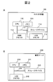
- FIG. 2A is a diagram showing an internal configuration of the host computer 100.
- the host computer 100 includes one or more CPUs 110, one or more memories 111, one or more SAN adapters 112, one or more LAN adapters 113, and one or more storage devices 114. These are connected to each other by an internal bus 115.
- the host computer 100 is connected to the storage apparatus 400 via the SAN adapter 112.
- the host computer 100 is connected to the management server 200 via the LAN adapter 113.
- the storage device 114 is not necessarily provided. If not provided, the volume in the storage device 400 may be used as a software storage area.
- FIG. 2B is a diagram illustrating an internal configuration of the management server 200.
- the internal configuration of the management server 200 is the same as that of the host computer 100, but does not necessarily include a SAN adapter.
- the management server 200 is connected to the storage apparatus 400 and the host computer 100 via the LAN adapter 212.
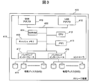
- FIG. 3 is a diagram showing an internal configuration of the storage apparatus 400.
- the storage apparatus 400 includes one or more controllers 410 and one or more physical disks 411.
- the controller 410 includes one or more CPUs 412, one or more memories 413, one or more NVRAMs 414, one or more cache memories 415, one or more back-end interfaces 416 and 417, and one or more.
- LAN adapter 418 and one or more SAN adapters 419 which are connected to each other via an internal bus 420.
- the controller 410 is connected to the physical disk 411 via the back-end interfaces 416 and 417. Further, the storage apparatus 400 is connected to the management server 200 via the LAN adapter 418. The storage apparatus 400 is connected to the host computer 100 via a SAN adapter 419.
- the physical disk 411 may be composed of a plurality of types of disks such as a SAS (Serial Attached SCSI (Small Computer System Interface)) disk, a SATA (Serial Advanced Technology Attachment) disk, and an SSD (Solid State Drive).
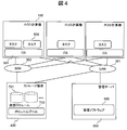
- FIG. 4 is a block diagram showing an outline of the software configuration of the computer system 10 of this embodiment.
- On the host computer 100 one or more tasks 500 and one or more OS (Operating System) 501 by an application operate. These software are stored in the storage device 114 or the storage apparatus 400, loaded into the memory 111, and executed using the CPU 110.
- OS Operating System
- management software 600 operates on the management server 200.
- the management software 600 is loaded into the memory 211 and executed using the CPU 210.
- volume pools 700 there are one or more volume pools 700 on the storage apparatus 400, and one or more virtual volumes 701 (described later) created from these.
- the virtual volume 701 is assigned to the host computer 100 via the SAN 300. In this system configuration, not only the virtual volume 701 but also logical volumes (real volumes) described later may be mixed.
- the OS 501 manages and executes a plurality of tasks 500, and recognizes and manages the virtual volume 701 and the logical volume 702.
- the management software 600 acquires configuration information from the host computer 100 and the storage system 400 and stores it in the management table. Details of the management software 600 will be described later.
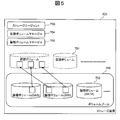
- FIG. 5 is a diagram showing an outline of the software configuration in the storage apparatus 400.
- a storage agent 703, a virtual volume manager 704, and a logical volume manager 705 are operating. These are stored in the physical disk 411 or the NVRAM 414, loaded into the memory 413, and executed using the CPU 412.
- the logical volume manager 705 is software that creates one or more logical volumes 702 from the physical disk 411 and manages the mapping between the logical volume 702 and the physical disk 411.
- the virtual volume manager 704 is software that creates one or more virtual volumes 701 from the logical volumes 702 registered in the volume pool 700 and manages the mapping between the virtual volumes 701 and the logical volumes 702.
- the virtual volume manager 704 is software that allocates an unused area from the logical volume 702 to a place where the virtual volume 701 is written when data is written to the virtual volume 701.
- FIG. 6 is a conceptual diagram showing the relationship between the logical volume 702 and the physical disk 411.
- the logical volume 702 is composed of four physical disks 800, 801, 802, and 803.
- the areas in the physical disk labeled 1-1, 1-2, 1-3,... Are areas divided into predetermined sizes and are called stripes.
- the areas labeled P1, P2,... Are areas that store parity information of corresponding stripes, and are called parity stripes.
- the volume management table 900 is held in the storage apparatus 400 so that the logical volume manager 705 manages the mapping relationship between the logical volume 702 and the physical disk 411. Details of the volume management table will be described later.
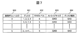
- FIG. 7 is a diagram showing a configuration example of the volume management table 900 held by the storage apparatus 400.
- the volume management table 900 includes a logical volume ID column 900, a disk column 901, a RAID level column 902, a stripe size column 903, and a disk type column 904.
- a logical volume manager 705 is assigned to each volume, and an identifier (identification information) for identifying and identifying each volume is registered.
- an identifier (identification information) for specifying and identifying a physical disk constituting the logical volume is registered.
- the RAID level column 902 the RAID level used for the configuration of the logical volume is registered.
- the stripe size column the stripe size used for the logical volume configuration is registered.
- the types of physical disks constituting the logical volume are registered.
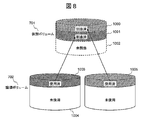
- FIG. 8 is a conceptual diagram showing the relationship between the virtual volume 701 and the logical volume 702.
- area allocation to a virtual volume does not directly allocate an area of a physical disk, but takes a form in which a partial area in a logical volume is allocated after a logical volume is configured as shown in FIG.
- the virtual volume manager 704 (FIG. 5) manages the relationship between the virtual volume 701 and the logical volume 702 included in the volume pool 700, and the hierarchy and usage status of the logical volume 702 in the volume pool. Therefore, the virtual volume management table 1100, the volume pool management table 1200, the pool tier management table 1300, and the unused area management table 1400 are held in the storage apparatus 400. Details of the virtual volume management table 1100, the volume pool management table 1200, the pool tier management table 1300, and the unused area management table 1400 will be described later.
- FIG. 9 is a diagram showing a configuration example of the virtual volume management table 1100 held by the storage apparatus 400.
- the virtual volume management table 1100 includes a virtual volume ID column 1101, a start LBA column 1102, an end LBA column 1103, a pool ID column 1104, and a page ID column 1105.
- an identifier (identification information) assigned to the virtual volume and for specifying / identifying it is registered.
- start LBA column 1102 the start LBA of the area in the virtual volume is registered.
- end LBA column 1103 the end LBA of the area in the virtual volume is registered.
- an identifier (identification information) for identifying and identifying a volume pool to which an area is assigned to a virtual volume is registered.
- Registered in the page ID column 1105 is an identifier (identification information) for identifying and identifying a page (detailed later) corresponding to each area (area specified by the start LBA and end LBA) in the virtual volume.
- FIG. 10 is a diagram showing a configuration example of the volume pool management table 1200 held by the storage apparatus 400.
- the volume pool management table 1200 includes a pool ID column 1201, a page ID column 1202, a logical volume ID column 1203, a start LBA column 1204, an end LBA column 1205, and a storage I / O number column 1206. .
- an identifier (identification information) that is assigned to a volume pool and identifies and identifies it is registered.
- an identifier (identification information) that is assigned to a page and identifies and identifies it is registered.
- a page is a unit of an area allocated from the volume pool 700 to the virtual volume 701. Each page. It is placed on one of the logical volumes in the volume pool.
- an identifier (identification information) for specifying and identifying the logical volume of the page arrangement destination is registered.
- start LBA column 1204 the start LBA of the page in the logical volume is registered.
- end LBA column 1205 the end LBA of the page in the logical volume is registered.
- the size of each page can be known from the start LBA and the end LBA. Generally, the page size is fixed, but each page can be registered as a different size by appropriately setting the start / end LBA.
- the storage I / O number column 1206 the number of I / O issued for each page is recorded.
- the I / O count is not required for the pool 2
- all the storage I / O counts 1206 of the pool 2 are “0”. Details of the storage I / O count 1206 will be described later.
- FIG. 11 is a diagram showing a configuration example of the pool tier management table 1300 held by the storage apparatus 400.
- the pool tier management table 1300 includes a pool ID column 1301, a tier column 1302, and a logical volume ID column 1303.
- an identifier (identification information) for specifying and identifying the volume pool is registered.
- tiers set in the volume pool are registered.
- the hierarchy is determined based on the disk type and RAID level of the logical volume, but may be defined by the user.
- identifier for specifying and identifying a logical volume belonging to each tier is registered.
- pool 1 is composed of two tiers, Tier 0 and Tier 1
- Tier 0 is composed of logical volumes 1 and 2
- Tier 1 is composed of logical volumes 0 and 3.
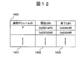
- FIG. 12 is a diagram showing a configuration example of the unused area management table 1400 held by the storage apparatus 400.
- the unused area management table 1400 is a table for managing an area that is not used in each logical volume, and includes a logical volume ID column 1401, a start LBA column 1402, and an end LBA column 1403.
- identifier for specifying and identifying a logical volume registered in the volume pool 700 is registered.
- start LBA column 1402 and the end LBA column 1403 the start LBA column and the end LBA column of the unused area 1004 in the logical volume 702 are registered.
- each logical volume is allocated to the logical volume in order of address and used.
- the used volume may be released to become an unused area. For this reason, as FIG. 12 shows, an unused area
- region may become discontinuous.
- the virtual volume manager 704 records the number of I / Os (the number of storage I / Os) issued from the host computer 100 to the pages constituting the virtual volume 701, and periodically based on the recorded number of storage I / Os.
- the page arrangement destination hierarchy is determined and the page is moved.
- recording the number of storage I / Os is called an I / O monitor, and determining a page arrangement destination hierarchy and moving a page is called page hierarchy rearrangement (rearrangement processing).
- the virtual volume manager 704 in addition to the above-described virtual volume management table 1100, volume pool management table 1200, pool tier management table 1300, and unused area management table 1400, for the I / O monitor and page tier relocation, the storage device 400 Is referred to the virtual volume I / O monitor ON / OFF management table.
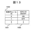
- FIG. 13 is a diagram showing a configuration example of the virtual volume I / O monitor ON / OFF management table 1500.
- the virtual volume I / O monitor ON / OFF management table 1500 includes a virtual volume ID column 1501 and an I / O monitor ON / OFF column 1502.
- an identifier (identification information) for specifying and identifying the virtual volume is registered.
- the I / O monitor ON / OFF column 1502 registers whether the number of I / Os for the virtual volume is recorded (ON) or not (OFF) during the I / O monitor process. As for the information of this I / O monitor ON / OFF 1502, a default value is set as an initial value. However, as the system is sequentially operated, a value (ON / OFF) is obtained by the processing of FIG. Is changing.
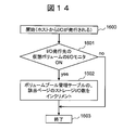
- FIG. 14 is a flowchart for explaining the I / O monitor process executed by the virtual volume manager 704. This process is started when an I / O is issued from the host computer 100 to the virtual volume 701 in the storage apparatus 400 (step 1600).
- Step 1601 The virtual volume manager 704 refers to the virtual volume I / O monitor ON / OFF management table 1500 and confirms whether the I / O monitor of the virtual volume to which the I / O is issued is ON. If it is ON (Yes in step 1601), the process proceeds to step 1602. If it is OFF (No in step S1601), the process ends (step 1603).
- Step 1602 The virtual volume manager 704 increments the number in the storage I / O number column 1206 in the row determined by the page ID of the I / O issue destination page and the pool ID of the volume pool in the volume pool management table 1200.
- the storage I / O number sequence 1206 is reset to 0 at regular intervals. At this time, the number of storage I / Os before the reset is retained as a history. May be.
- the volume pool management table 1200 holds time zone information in which the number of storage I / Os is recorded. That is, in this case, the volume management table 1200 is as shown in FIG.
- ON / OFF of the I / O monitor may be executed not in units of virtual volumes but in units of WWNs that are identifiers of the SAN adapter 112 of the host computer 100.
- step 1601 instead of the virtual volume I / O monitor ON / OFF management table 1500, the virtual volume ID column 1501 of the virtual volume I / O monitor ON / OFF management table 1500 is replaced with the host WWN column. Used, and the presence / absence of I / O recording is determined by the WWN of the I / O issuer. That is, the number of I / Os issued by the I / O issuer is counted.
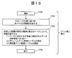
- FIG. 15 is a flowchart for explaining the page hierarchy rearrangement process executed by the virtual volume manager 704. This process is started for each volume pool when a certain time elapses or when the user manually executes the process (step 1700). Hereinafter, description will be described for each step.
- Step 1701 The virtual volume manager 704 determines the placement destination tier of each page based on the storage I / O count of each page recorded in the storage I / O count column 1206 of the volume pool management table 1200.
- the method of determining the placement destination tier may be, for example, a method of allocating placement destinations from the upper tier in descending order of the number of storage I / Os, or a method of allocating placement destinations from the lower tier in order of increasing storage I / O counts.
- not only the latest record recorded in the storage I / O number sequence 1206 as the storage I / O number, but also the past storage I / O number history may be taken into consideration to determine the placement destination tier of each page.
- not only the number of storage I / Os but also other indexes may be used for determination. When considering the history, an average value of the number of I / Os for the past several hours is taken. If the history is considered in this way, the number of I / Os increases instantaneously, but relocation is not performed when the number of I / Os is hardly counted in other periods (time zones). Can do.
- the placement destination tier may be determined in consideration of only the number of reads. Further, the placement destination layer may be determined in consideration of an index such as the number of random accesses and the number of sequential reads.
- the number of I / Os, the number of random accesses, the number of sequential reads, and the like can be collectively referred to as access characteristics and access characteristics.
- Step 1702 The virtual volume manager 704 executes page movement (rearrangement) based on the hierarchical arrangement of each page determined in step 1701. At this time, only the pages in which the determined hierarchy is different from the currently arranged hierarchy are targeted for movement. Note that the currently arranged tiers of each page can be confirmed by combining the volume pool management table 1200 and the pool tier management table 1300.
- Page movement consists of the following three transaction processes for each page. That is, (i) Copy the data of the area (old area) of the logical volume where the page is currently allocated to the unused area (new area) of the logical volume belonging to the determined hierarchy, (ii) Volume pool Updating the logical volume ID column 1203, the start LBA column 1204, and the end LBA column 1205 of the management table 1200 to the values of the new area, and (iii) updating the rearrangement page management table (details will be described later). After the processes (i) to (iii) are applied to all the pages to be moved, the process ends (step 1703).
- FIG. 16 is a diagram showing a configuration example of the rearrangement page management table 1800 held by the storage apparatus 400.
- the rearranged page management table 1800 is a table that holds information on the movement history of pages that have been moved in the page hierarchy rearrangement process.
- an identifier (identification information) for identifying and identifying the volume pool is registered.
- an identifier (identification information) for identifying and identifying the page that has been moved in the hierarchy in the page hierarchy rearrangement process is registered.
- the page arrangement destination hierarchy before and after the page hierarchy rearrangement process is recorded.
- the destination tier 1804 becomes the source tier 1803 during the next rearrangement process.
- the rearrangement page management table 1800 may hold not only the record of the page layer rearrangement process executed immediately before but also the history of the page layer rearrangement process of the past. In this case, the rearrangement page management table 1800 holds the time when the page hierarchy rearrangement process is executed. In FIG. 16, only upgrade and downgrade are shown, but the hierarchy may not change.
- the storage agent 703 assigns and manages a storage volume ID (described later) to the logical volume 702 and the virtual volume 701.
- the logical volume 702 and the virtual volume 701 are collectively referred to as a storage volume.
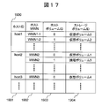
- FIG. 17 is a diagram showing a configuration example of the host volume management table 1900 held by the management server 200.
- the host volume management table 1900 is created by the management software 600 acquiring information from the host computer 100.
- the host volume management table 1900 includes a host ID column 1901, a host WWN column 1902, a host volume ID column 1903, and a storage volume ID column 1904.
- an identifier (identification information) assigned by the management software 600 for identifying and identifying the host computer 100 is registered.
- an identifier for identifying and identifying the SAN adapter 112 of the host computer 100 is registered. This information can be used when monitoring the number of I / Os in WWN units.
- a volume recognized by the host computer 100 is referred to as a host volume.
- the storage volume ID column 1904 an identifier (identification information) for specifying and identifying the storage volume corresponding to the host volume is registered.
- the storage volume ID is information given by the storage agent 703 to each storage volume.
- the storage volume ID is information that the storage agent 703 assigns / holds, but the OS 501 acquires and holds the storage volume ID from the storage apparatus 400 using, for example, SCSI Inquiry.
- the storage volume ID is represented in the form of “virtual volume 0” and “logical volume 3” in FIG. 17, but in reality, in many cases, the storage agent 703 distinguishes the virtual volume from the logical volume. Instead, it is assigned and managed with a serial number. In this case, the management software 600 can obtain the correspondence between the storage volume ID, the virtual volume ID, and the logical volume ID by inquiring the storage agent 703.
- “virtual volume ID specified from the storage volume ID” or “logical volume ID specified from the storage volume ID” What should be described may be simply expressed as a virtual volume ID or a logical volume ID.
- the host volume and the storage volume correspond one-to-one, but it does not necessarily have to be one-to-one, and may be one-to-many or many-to-one.
- FIG. 18 is a diagram showing a configuration example of the I / O monitor necessity management table 2000 held by the management server 200 and referred to by the management software 600.
- the I / O monitor necessity management table 2000 includes a host ID column 2001, a task name column 2002, a task type column 2003, and an I / O monitor necessity column 2004.
- an identifier (identification information) assigned by the management software 600 for identifying and identifying the host computer 100 is registered.
- This information is, for example, all “default” by default as an initial value (when the necessity of monitoring for a specific task is known from the beginning, the administrator sets “necessary” or “not required”.
- the user may decide based on the display in FIG. 21 described later, or in FIGS. 24 and 26 described later.
- the necessity of monitoring may be automatically determined as “No” by processing.
- the I / O monitor necessity management table 2000 may be created by a user input to the management software 600, or a method in which the management software 600 detects the task 500 operating on the OS 501 and automatically creates it. But you can.
- the I / O monitor necessity management table 2000 is created before the I / O monitor ON / OFF control process.
- monitoring of nighttime batch processing tends to be unnecessary, but monitoring may be required because batch processing is not always completed on time.
- batch processing when there is a large number of accesses to a volume and there is a possibility that it will not be in time for the scheduled end time, it is inconvenient if each page remains arranged in a hierarchy with a low access speed. In this case, it is more efficient to monitor and enable the rearrangement process. In this way, tasks that do not need to be monitored are not always apparent on the surface, and the processing of the present invention becomes very effective.
- FIG. 19 is a flowchart for explaining an ON / OFF control process (example) of the I / O monitor executed by the management software 600 in the management server 200. This process is periodically started for each host (step 2100).
- “periodic” includes not only the case of executing periodically, but also the case of executing at the time set by the user, at the time set by the user. This includes the case where It should be noted that not only the number of storage I / Os but also other indicator monitoring ON / OFF may be controlled.
- monitoring ON / OFF of the total number of reads / writes from the host computer 100 is not controlled, but monitoring ON / OFF of only the number of reads is controlled. Also, it may be ON / OFF of an index such as the number of random accesses and the number of sequential reads. In other words, in the present embodiment, it can be said that the access property or access property monitor ON / OFF is controlled.
- description will be given for each step of the ON / OFF control of the I / O monitor.
- Step 2101 The management software 600 communicates with each host computer 100, and acquires task operation information 2200 (see FIG. 20) for each host computer 100 from the OS 501 on the host computer 100.
- Step 2102 In the acquired task operation information, the management software 600 indicates that “operation state 2202 is ON” and the value of the I / O monitor necessity column 2004 in the I / O monitor necessity management table 2000 is “No”. It is determined whether there is at least one task such as This is to turn off the I / O monitor for a virtual volume in which a task that should not be I / O monitored is running.
- the monitor OFF condition may be “the host I / O issue amount 2203 is greater than or equal to the threshold” instead of “the operation state 2202 is ON”.
- “determine whether there is at least one” or “threshold (for example, three tasks with“ No ”) or more” may be used, and all tasks are not “No”. The monitor may not be turned off. If the determination result in step 2102 is yes, the process proceeds to step 2103, and if the determination result is no, the process proceeds to step 2104.
- Step 2103 The management software 600 turns off the I / O monitor of the virtual volume assigned to the host computer 100. Specifically, first, the management software 600 identifies the virtual volume ID of the virtual volume assigned to the host computer 100 from the host volume management table 1900 (FIG. 17), and identifies the virtual volume ID and I for the storage apparatus 400. / O Monitor OFF command is transmitted. Then, the storage apparatus 400 that has received the OFF command turns OFF the value of the I / O monitor ON / OFF column 1502 of the corresponding virtual volume ID in the virtual volume I / O monitor ON / OFF management table 1500 (FIG. 13). To do.
- Step 2104 The management software 600 turns on the I / O monitor 1502 of the virtual volume assigned to the host computer 100. Specifically, first, the management software 600 specifies the virtual volume ID of the virtual volume assigned to the host computer 100 from the host volume management table 1900, and the I / O monitor including the virtual volume ID for the storage apparatus 400. Send an ON command. Then, the storage apparatus 400 that has received the ON command turns ON the value of the I / O monitor ON / OFF column 1502 of the corresponding virtual volume ID in the virtual volume I / O monitor ON / OFF management table 1500.
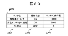
- FIG. 20 is a diagram showing an example of task operation information 2200 for each host computer.
- the task operation information 2200 includes a task name 2201, an operation state 2202, and a host I / O issue amount 2203.
- the task name 2201 is information for identifying a name that distinguishes the task 500 on the OS 501.
- the operating state 2202 is information indicating whether each task is operating (ON) or not (OFF).
- the host I / O issue amount 2203 is information indicating the number of I / Os per time that each task issues on the OS 501.
- task operation information 2200 may include other information such as memory usage.
- FIG. 21 is a diagram illustrating a configuration example of the information display screen 2300 for determining I / O monitor ON / OFF displayed by the management software 600 in the management server 200.
- the I / O monitor ON / OFF determination information display screen 2300 is used to determine which task the I / O monitor should be turned off when the user inputs the I / O monitor necessity management table 2000. It is a screen to do.
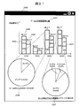
- FIG. 21 shows a user interface for managing the amount of relocation generated for each pool of the virtual logical volume 701. Note that the amount of rearrangement generated for each pool is monitored not only in the first embodiment but also in the second to fourth embodiments.
- the I / O monitor ON / OFF determination information display screen 2300 is roughly divided into three components. That is, the intra-pool relocation generation amount graph 2301, the in-host task I / O ratio graph 2306, and the all-host tier upgrade page I / O contribution rate graph 2307.
- the in-host task I / O ratio graph 2306 and the all host tier upgrade page I / O contribution rate graph 2307 pay particular attention to tier upgrade (movement from a lower tier to an upper tier).
- Similar graphs may also be displayed by calculation described below with regard to hierarchy downgrade (movement from an upper hierarchy to a lower hierarchy). In addition, the calculation described below is an example.
- the in-pool relocation generation amount graph 2301 is a total of tier upgrade page groups (that is, one or more pages moved from a lower tier to an upper tier) for each page tier rearrangement process in each time zone of the volume pool 700.
- the capacity (hierarchy upgrade capacity 2304) and the breakdown 2302 of the host computer to which the page group is allocated are displayed for each time zone when the page hierarchy rearrangement process is executed. Similar information is also displayed for the hierarchical downgrade page group (that is, one or more pages moved from the upper hierarchy to the lower hierarchy) (ie, the hierarchical downgrade capacity 2305 and the breakdown 2303 of the host computer to which the page group is assigned). ).
- Whether the page is upgraded or downgraded can be determined from the rearranged page management table 1800 (see FIG. 16). Further, since the LBA range of each page is known from the volume pool management table 1200 (FIG. 10), the capacity of each page can be calculated based on this. Which page is assigned to which host computer is determined by referring to the virtual volume management table 1100 (FIG. 9), specifying the virtual volume corresponding to the page ID, and the host computer to which the virtual volume ID is assigned. Can be determined by referring to the host volume management table (FIG. 17).
- the user can determine which host computer 100 is the cause of the tier upgrade and tier downgrade by referring to the intra-pool relocation generation amount graph 2301. Further, the in-pool rearrangement generation amount graph 2301 is displayed based on the rearrangement capacity management table 2400 (see FIG. 22).
- the in-host task I / O ratio graph 2306 is obtained by, for example, selecting a host computer (for example, “upgraded host 3” at 24:00) in the time zone to be confirmed on the in-pool relocation generation amount graph 2301. It is a graph to be displayed.
- a host computer for example, “upgraded host 3” at 24:00
- the in-host task I / O ratio graph 2306 shows the “ratio of the host I / O issuance amount of each task 500 in each host computer 100” in a certain time zone when the page hierarchy rearrangement process is executed.
- the user can determine the task 500 that caused the rank upgrade of the page group corresponding to each host computer 100 in the page layer rearrangement process in a certain time zone by using the in-host task I / O ratio graph 2306. As shown in FIG. 21, it can be seen that in the relocation processing of the host 3 at 24:00, the anti-virus A was upgraded.
- step 1701 of the page tier relocation process the management software 600 records the number of storage I / O used for determining the page layout destination tier in each time zone. The calculation is performed based on the host I / O issue amount of the task 500. For example, in step 1701, when not only the latest storage I / O number but also the past storage I / O number retained as a history is used, the past storage I / O number is included in the calculation. However, in many cases, the past number of storage I / Os is less important than the latest number of storage I / Os as a consideration for page relocation processing.
- the virtual volume manager 704 may multiply the past storage I / O number by an appropriate constant (weight coefficient) when executing step 1701 so that the contribution rate is lower than the latest storage I / O number. good.
- the management software 600 calculates “the ratio of the host I / O issuance amount of each task 500 in each host computer 100”
- the virtual volume manager 704 sets the past storage I / O count in step 1701.
- the host I / O issue amount of each task in the time zone is multiplied by the same coefficient as that multiplied for the task.
- the calculation of “the ratio of the host I / O issue amount of each task 500 in each host computer 100” is executed based on the task operation information management table 2500 (see FIG. 23).
- the management software 600 sums up the host I / O issuance amounts from 18:00 to 24:00 for each of the tasks of host3 in the task operation information management table 2500, that is, OLTP3 and antivirus A.
- the ratio of the total value is “the ratio of the host I / O issuance amount used for displaying the host 3 task I / O ratio graph 2306 at 2 o'clock”.
- All host tier upgrade page I / O contribution ratio graph 2307 is, for example, a host computer (for example, “upgrade host 3” and “upgrade at 6:00” in the time zone to be confirmed on the intra-pool relocation occurrence amount graph 2301. It is a graph displayed by selecting the host 2 ").
- the all-host tier upgrade page I / O contribution ratio graph 2307 shows “the tier upgrade contribution ratio of each task 500 in all the host computers 100” for each time zone in which the page tier relocation processing is executed.
- the user determines which task 500 of which host computer 100 caused the tier upgrade in the page tier rearrangement process in a certain time zone by referring to the all-host tier upgrade page I / O contribution ratio graph 2307. it can.
- FIG. 21 in the relocation process at 6:00, it can be seen that OLTP2 of the host 2 is dominant and this is a factor of the upgrade. Therefore, if the OLTP2 process is important, the necessity of I / O monitoring should be left as “necessary”, and if not important, it should be set to “No”. It should be noted that even if OLTP3 and anti-virus A having a small ratio are “No”, it can be said that the effect of preventing performance degradation by preventing them from being arranged in a lower hierarchy is small.
- the “upgrade contribution ratio of each task 500 in all host computers 100” displayed in the all-host tier upgrade page I / O contribution ratio graph 2307 is “each host displayed in the in-host task I / O ratio graph 2306”.
- the management software 600 calculates from “the ratio of the host I / O issuance amount of each task 500 in the computer 100” and “the breakdown of host computers 2302 of the tier upgrade capacity 2304”. That is, the ratio of “the host computer breakdown 2302 of the tier upgrade capacity 2304” multiplied by “the ratio of the host I / O issuance amount of each task 500 in each host computer 100” is multiplied by “in all the host computers 100”. "Tier upgrade contribution rate of each task 500".
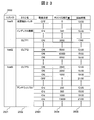
- FIG. 22 is a diagram showing a configuration example of the relocation capacity management table 2400 created by the management software 600 and held in the management server 200.
- the relocation capacity management table 2400 includes a pool ID column 2401, a host ID column 2402, a relocation time zone column 2403, a tier upgrade capacity column 2404, and a tier downgrade capacity column 2405.
- an identifier (identification information) for identifying and identifying the volume pool 700 is registered.
- an identifier (identification information) for identifying and identifying a host computer to which a virtual volume created from the volume pool specified by the value of the pool ID column 2401 is assigned is registered.
- rearrangement time zone column 2403 information indicating the time zone when the page tier rearrangement processing is executed in the storage apparatus 400 is registered.
- the total capacity of the page groups moved from the lower hierarchy to the upper hierarchy and from the upper hierarchy to the lower hierarchy in the page hierarchy rearrangement process is registered, respectively.
- the management software 600 rearranges the host volume management table 1900, the virtual volume management table 1100 acquired from the storage device 400, the volume pool management table 1200, and so on. Calculation is performed using the page management table 1800. For example, in the case of calculating “upgrade layer capacity of host 1 of pool 1”, “the value of the destination layer column 1804 is higher than the source layer column 1803” in the page group of pool 1 registered in the rearranged page management table 1800. Yes, and “the host computer to which the corresponding virtual volume is assigned is host1” is identified. This specification can be executed by combining the virtual volume management table 1100 and the host volume management table 1900. The capacity of each identified page is acquired from the volume pool management table 1200 and summed to calculate the “upgraded capacity of host1 in pool1”.
- FIG. 23 is a diagram illustrating a configuration example of the task operation information management table 2500 held by the management server 200.
- the task operation information management table 2500 holds history information of the task operation information 2200 of each host computer 100, and the management software 600 periodically acquires the task operation information 2200 from each host computer 100 to generate / The table to be updated.
- the task operation information management table 2500 includes a host ID column 2501, a task name column 2502, an operation state column 2503, a host I / O issue amount column 2504, and a collection time column 2505.
- an identifier (identification information) for identifying and identifying the host computer 100 is registered.
- the information registered in the task name column 2502, the operation status column 2503, and the host I / O issue amount column 2504 is the same as the item of the same name in the task operation information 2200, and the description thereof is omitted here.
- the time when the management software 600 acquires the task operation information 2200 is registered.
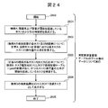
- FIG. 24 is a flowchart for explaining an I / O monitor OFF recommended display process (example).
- the management software 600 automatically presents the task 500 for which the I / O monitor should be turned off to the user by this processing.
- the user since the user (administrator) determines the task for turning off the I / O monitor from each displayed graph, the task is automatically presented, unlike the case of FIG. There is an advantage that the user does not need to judge.
- the task 500 that is to be turned off the I / O monitor presented by this process is a type of task that has caused a hierarchical upgrade and generally should turn off the I / O monitor.
- This process is executed for each pool of the reallocation capacity management table 2400 periodically or triggered by a user instruction (step 2600).
- the page hierarchy rearrangement process has been executed at least once, and the data needs to be stored in the rearrangement capacity management table 2400 and the task operation information management table 2500.
- the meaning of “periodic” is as described above.
- description will be described for each step.
- Step 2601 The management software 600 refers to the relocation capacity management table 2400 and searches for the host computer 100 in which the value of the hierarchical upgrade capacity column 2404 exceeds a predetermined threshold and its relocation time zone. For example, if the threshold is 20 GB (or more), the relocation capacity management table 2400 indicates that the host 1 at 20: 00-24: 00, the host 2 at 12: 00-18: 00, and the host at 6: 00-12: 00 Host 2 and host 3 from 24: 00-6: 00 are detected.
- the threshold is 20 GB (or more)
- the relocation capacity management table 2400 indicates that the host 1 at 20: 00-24: 00, the host 2 at 12: 00-18: 00, and the host at 6: 00-12: 00 Host 2 and host 3 from 24: 00-6: 00 are detected.
- Step 2602 The management software 600 calculates “the ratio of the host I / O issue amount of each task 500 in each host computer 100” for each “host computer 100 and relocation time zone” found in the search of step 2601. .
- the “ratio of the host I / O issue amount of each task 500 in each host computer 100” is the same as that used when the in-host task I / O ratio graph 2306 is displayed.
- Step 2603 The management software 600 uses the calculation result of Step 2602 (“the ratio of the host I / O issue amount of each task 500 in each host computer 100” to each “host computer 100 and relocation time zone”), “A task of a type registered as an I / O monitor OFF candidate in the I / O monitor OFF candidate management table 2700 (FIG. 25) for each task type” and “Host I / O of each task 500 in each host computer 100.
- the task 500 is searched such that the ratio of the O issue amount exceeds a predetermined threshold.
- Step 2604 If there is the task 500 obtained by the search in step 2603, the management software 600 presents the I / O monitor to the user as a task to be turned off.
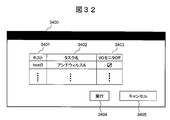
- FIG. 32 is a diagram illustrating a configuration example of the I / O monitor control setting recommendation display screen 3400 presented in step 2604.
- the I / O monitor control setting recommendation display screen 3400 includes a host name 3401, a task name 3402, an I / O monitor OFF check box 3403, an execute button 3404, and a cancel button 3405.
- the user can turn off the I / O monitor of the task by checking the I / O monitor OFF check box 3403 and pressing the execution button 3404. That is, the value in the I / O monitoring necessity column 2004 of the row of the task in the I / O monitoring necessity management table 2000 can be changed to “No”. Information other than this may be displayed. Further, in this step, not only the task for turning off the I / O monitor is presented to the user, but the I / O monitor may be automatically turned off.
- FIG. 25 is a diagram showing a configuration example of a task type I / O monitor OFF candidate management table 2700 held in the management server 200 and referred to by the management software 600.
- the task type I / O monitor OFF candidate management table 2700 includes a task type column 2701 and an I / O monitor OFF candidate column 2702.
- task type column 2701 general types of tasks executed on the host computer 100 are registered.
- each task type should generally be set to I / O monitor OFF (yes) or not (no) is registered. For example, in general, an index construction task issues a large amount of I / O to construct an index, but this I / O is also issued to data that originally does not require high response. Should not be recorded (I / O monitor should be OFF).
- the I / O monitor OFF candidate management table 2700 for each task type may be held as a fixed value (Default value) by the management software 600 from the beginning, or may be appropriately input by the user.
- FIG. 26 is a flowchart for explaining an I / O monitor OFF recommended display process different from FIG.
- the management software 600 presents a task 500 for which the I / O monitor should be turned off to the user.
- the task 500 (task A) for which the I / O monitor to be turned off presented by this processing has generated a tier upgrade exceeding a predetermined threshold in a certain page tier relocation time zone, and the next In the page hierarchy rearrangement time zone, another one or more tasks 500 (task B group) are generating a large number of hierarchy upgrades.
- a time zone in which a rearrangement process equal to or greater than a predetermined threshold is executed among two (but not necessarily two) continuous time zones is detected.
- This is not intended to be a time zone in which the amount of generation of hierarchical upgrades increases, but a time zone in which hierarchical upgrades occur to some extent on a regular basis.
- the host I / O issuance amount temporarily increases, and the page group used in the task A in the page hierarchy rearrangement process is hierarchically upgraded.
- the page of the task B group is hierarchically demoted.
- This process is executed for each pool of the relocation capacity management table 2400 periodically or triggered by a user instruction (step 2800).
- Step 2801 The management software 600 refers to the relocation capacity management table 2400, and sums up all hosts of the tier upgrade capacity for both the relocation time zone of interest (also referred to as the self-relocation time zone) and the relocation time zone immediately thereafter. A relocation time zone in which the value exceeds a predetermined threshold is searched. Instead of the “self-relocation time zone and the immediately following rearrangement time zone”, it may be “the self-relocation time and any one of the k rearrangement time zones immediately after” (k is an arbitrary natural number) is there).
- the total value of tier upgrade capacity of host 2 and host 3 from 24:00 to 6:00 (50 GB), and the total value of tier upgrade capacity of host 2 and host 3 from 6:00 to 12:00 (40 GB) Since both exceed a predetermined threshold value (for example, 35 GB), these time periods are detected as targets for continuing the subsequent processing.
- a predetermined threshold value for example, 35 GB
- Step 2802 The management software 600 calculates “the layer upgrade contribution ratio of each task 500 in all host computers 100” for each relocation time zone obtained in step 2801 and the relocation time zone immediately after each. .
- the “tier upgrade contribution ratio of each task 500 in all host computers 100” is the same as the information used for displaying the all host hierarchy upgrade page I / O contribution ratio graph 2307.
- the management software 600 is a task 500 whose contribution rate exceeds the threshold in the “tier upgrade contribution rate of each task 500 in all host computers 100” in an arbitrary relocation time zone calculated in Step 2802.
- the task 500 whose contribution rate is lower than the threshold in the “tier upgrade contribution rate of each task 500 in all the host computers 100” in the relocation time zone immediately after that is acquired.
- the anti-virus A is acquired as a corresponding task.
- Step 2804 If there is the task 500 obtained by the search in Step 2803, the management software 600 presents the I / O monitor to the user as a task to be turned off. Note that the information presented in step 2804 is the same as the I / O monitor control setting recommendation display screen 3400 shown in FIG. In addition to notifying the user of the task for which the I / O monitor should be turned off, the I / O monitor may be automatically turned off.
- the I / O monitor OFF recommended display processing shown in FIG. 24 and FIG. 26 is an example, and there is other I / O monitor OFF recommended display processing.
- the following task 500 may be presented to the user as a task for which the I / O monitor should be turned off.
- the task 500 generates a large number of hierarchy upgrades in a certain page hierarchy rearrangement time zone, and many of the page groups that have been upgraded at that time have not been accessed much after the hierarchy upgrade. is there.
- Such a task 500 temporarily increased host I / O issuance volume and caused a large number of tier upgrades, but since then access has decreased, resulting in meaningless tier upgrades. High nature.
- Such a task 500 can be specified by using the volume management table 1100, the relocation page management table 1800, the virtual host volume management table 1900, the relocation capacity management table 2400, and the task operation information management table 2500.
- FIGS. 1 to 12, FIGS. 15 to 18, and FIGS. 20 to 26 used in the first embodiment. This will be further described with reference to FIGS.
- the difference between the first and second embodiments is the granularity of the ON / OFF control of the I / O monitor. That is, in the first embodiment, ON / OFF of the I / O monitor is controlled in units of virtual volumes, but in the second embodiment, ON / OFF of the I / O monitor is controlled in units of pages.
- the system configuration in the second embodiment is the same as that described with reference to FIGS. 1 to 5 in the first embodiment.
- the conceptual diagrams, management tables, and flowcharts shown in FIGS. 6 to 12, 15 to 18, and 20 to 26 are also applied to this embodiment.
- the virtual machine 701 is not used as a host volume as it is, but a part or a plurality of areas on one or more virtual volumes 701 are used as virtual host volumes.
- a program (host volume manager) to be used above may exist on the host computer 100 or another computer.
- the host volume manager holds mapping information between the virtual host volume and the part or a plurality of areas.
- the host computer 100 not only a physical machine but also a virtual machine may exist.
- FIG. 27 is a diagram showing a configuration example of the page I / O monitor ON / OFF management table 2900. This table is for managing ON / OFF of the I / O monitor in units of pages.
- FIG. 13 in the first embodiment (table for managing ON / OFF of the I / O monitor in units of virtual volumes) Corresponding to
- the page I / O monitor ON / OFF management table 2900 includes a pool ID column 2901, a page ID column 2902, and an I / O monitor ON / OFF column 2903.
- an identifier (identification information) for identifying and identifying the volume pool 700 is registered.
- an identifier (identification information) for identifying and identifying each page of each volume pool 700 is registered.
- I / O monitor ON / OFF column 2903 it is registered whether I / O is recorded (ON) or not (OFF) for the page during the I / O monitor processing. Note that this information has a default value set as an initial value as in the case of the I / O monitor ON / OFF 1502 in FIG. 13, but as the system is operated sequentially, the value (ON) / OFF) changes.
- FIG. 28 is a flowchart for explaining an I / O monitor process (example) executed by the virtual volume manager 704 in the second embodiment. This process is started when an I / O is issued from the host computer 100 to the virtual volume 701 in the storage apparatus 400 (step 3000).
- the virtual volume manager 704 refers to the page I / O monitor ON / OFF management table 2900 and confirms whether the I / O monitor ON / OFF 2903 of the I / O issue destination page is ON (step 3001). ). At this time, if the I / O monitor ON / OFF 2903 is OFF, the process ends (step 3003). If the I / O monitor ON / OFF 2903 is ON, the process proceeds to step 3002.
- the virtual volume manager 704 increments the number in the storage I / O number column 1206 in the row determined by the page ID of the I / O issue destination page and the pool ID of the volume pool in the volume pool management table 1200 by 1 ( Step 3002) and the process is terminated (Step 3003).
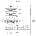
- FIG. 29 is a flowchart for explaining the ON / OFF control processing (example) of the I / O monitor executed by the management software 600. This process is periodically started for each host computer 100 (step 3100). Note that the meaning of “periodic” is as described above in the first embodiment. The explanation is described for each step below.
- Step 3101 The management software 600 acquires task operation information 2200 (see FIG. 20) from the OS 501 on the host computer 100.
- Step 3102 The management software 600 identifies a page group assigned to the host computer 100.
- the management software 600 first acquires the LBA range on the virtual volume 701 used by the host computer 100 from the OS 501 on the host computer 100.
- the OS 501 of the host computer 100 manages the LBA range on the virtual volume 701 used by the host computer.
- the management software 600 acquires the LBA range corresponding to the area from the host volume manager. To do.
- the management software 600 can identify the page group allocated to the host computer 100 by collating the acquired LBA range using the virtual volume management table 1100 (see FIG. 9).
- Step 3103 In the task operation information 2200 acquired in Step 3101, the management software 600 indicates that “operation state 2202 is ON” and the value of the I / O monitor necessity column 2004 in the “I / O monitor necessity management table 2000” is “ It is determined whether there is even one task such as “No”. If the determination result in step 3103 is yes, the process proceeds to step 3104, and if the determination result is no, the process proceeds to step 3105. Note that, as a condition, instead of “the operation state 2202 is ON”, “the host I / O issue amount 2203 is equal to or greater than the threshold” may be used. Also, “determine whether there is at least one” or “determine whether there is more than a threshold” or the like. The modification is the same as that of the first embodiment.
- Step 3104 The management software 600 turns off the I / O monitor of the page group specified in Step 3102. That is, an I / O monitor OFF command including a volume pool identifier and a page group page ID is transmitted to the storage apparatus 400. Then, the storage apparatus 400 that received it turns OFF the value of the I / O monitor ON / OFF column 2903 of the corresponding pool ID and page ID in the page I / O monitor ON / OFF management table 2900 (FIG. 27). .
- Step 3105 The management software 600 turns on the I / O monitor of the page group specified in Step 3102. That is, an I / O monitor ON command including the pool ID of the volume pool and the page ID of the page group is transmitted to the storage apparatus 400. Then, the storage apparatus 400 that has received it turns ON the value of the corresponding pool ID and page ID I / O monitor ON / OFF column 2903 of the page I / O monitor ON / OFF management table 2900.
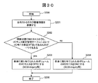
- FIGS. 1 to 18 and FIGS. 20 to 26 used in the first embodiment and FIG. 30 are newly added. Will be described with reference to FIG.
- the difference between the third embodiment and the first embodiment is that the ON / OFF control processing of the I / O monitor is not executed by the management software 600 of the management server 200, but on each host computer 100. It is executed by the OS 501 or the OS 501 of the representative host computer. Therefore, the role of the management software 600 is to present the I / O monitor ON / OFF determination information display screen 2300 (FIG. 21) to the user.
- the system configuration in the present embodiment is the same as that described in Embodiment 1 with reference to FIGS.
- the conceptual diagrams, management tables, and flowcharts shown in FIGS. 6 to 18 and FIGS. 20 to 26 are also applied to this embodiment.
- the management software 600 is not necessarily required.
- the I / O monitor necessity management table 2000 is held by the management software 600, and each host computer 100 holds partial information (task name, task type, I / O monitor necessity) of each host ID. .
- the partial information of the I / O monitor necessity management table 2000 held by the management software 600 and the I / O monitor necessity management table held by each host computer 100 are synchronized. Therefore, when the user inputs the I / O monitor necessity management table 2000, it may be input on the management software 600 or on each host computer 100.
- FIG. 30 is a flowchart illustrating an example of an I / O monitor ON / OFF control process. This process is periodically started by the OS 501 on each host computer 100 (step 3200). The meaning of “periodic” is as described above. The explanation is described for each step below.
- Step 3201 The OS 501 on each host computer 100 refers to the task operation information 2200 (FIG. 20) of each host computer (own host).
- Step 3202 The OS 501 on each host computer 100 indicates that the “operation status 2202 is ON” and the value of the I / O monitor necessity column 2004 in the I / O monitor necessity management table 2000 is “No” in the task operation information 2200. It is determined whether at least one task such as “is” exists. If the determination result in step 3202 is yes, the process proceeds to step 3203, and if the determination result is no, the process proceeds to step 3204. As a precondition for the task, “the host I / O issue amount 2203 is equal to or larger than the threshold” may be used instead of “the operation state is ON”. Also, “determine whether there is at least one” or “determine whether there is more than a threshold” or the like. The modification is the same as that of the first embodiment.
- Step 3203 The OS 501 on each host computer 100 turns off the I / O monitor of the volume assigned to each corresponding host computer (own host computer).
- an I / O monitor OFF command including a virtual volume ID is issued to the storage apparatus 400 by, for example, SCSI Inquiry.
- the storage apparatus 400 Upon receiving this OFF command, the storage apparatus 400 turns OFF the value of the I / O monitor ON / OFF column 1502 of the corresponding virtual volume ID in the virtual volume I / O monitor ON / OFF management table 1500 (FIG. 13). .
- Step 3204 The OS 501 on each host computer 100 turns on the I / O monitor of the volume assigned to each corresponding host computer (own host computer).
- an I / O monitor ON command including a virtual volume ID is issued to the storage apparatus 400 by, for example, SCSI Inquiry.
- the storage apparatus 400 that has received this ON command turns ON the value of the I / O monitor ON / OFF column 1502 of the corresponding virtual volume ID in the virtual volume I / O monitor ON / OFF management table 1500.
- FIGS. 1 to 12, FIGS. 15 to 18, and FIGS. 20 to 26 used in the first embodiment. This will be described with reference to FIGS. 27 and 28 used in the second embodiment and FIG. 31 newly.
- the difference between the first embodiment and the fourth embodiment is that the management software 600 does not execute the ON / OFF control of the I / O monitor, but the OS 501 on each host computer 100 executes. And “I / O monitor ON / OFF control is executed in units of pages”. That is, the second embodiment and the third embodiment are combined. Therefore, the role of the management software 600 is to present the I / O monitor ON / OFF determination information display screen 2300 to the user.
- the system configuration in this embodiment is the same as that described with reference to FIGS. 1 to 5 in the first embodiment.
- the conceptual diagrams, management tables, and flowcharts shown in FIGS. 6 to 18 and 20 to 26 are also applied to this embodiment.
- the management software 600 is not necessarily required.
- the I / O monitor necessity management table 2000 is held by the management software 600, and each host computer 100 holds partial information (task name, task type, I / O monitor necessity) of each host ID. It will be.
- the I / O monitor necessity management table 2000 held by the management server 200 and used by the management software 600 and the partial information of the I / O monitor necessity management table held by each host computer 100 are synchronized. Therefore, when the user inputs the I / O monitor necessity management table 2000, it may be input on the management software 600 of the management server 200 or on each host computer 100. Further, a program for using a part or a plurality of areas on one or more virtual volumes 701 as virtual host volumes on the host computer 100 instead of using the virtual volumes 701 as host volumes as they are. (Host volume manager) may exist on the host computer 100 or on another computer. The host volume manager holds mapping information between the virtual host volume and the part or a plurality of areas.
- FIG. 31 is a flowchart for explaining an ON / OFF control process (example) of the I / O monitor according to the fourth embodiment. This process is periodically started by the OS 501 on each host computer 100 (step 3300). The meaning of “periodic” is as described above. The explanation is described for each step below.
- Step 3301 The OS 501 on each host computer 100 refers to the task operation information 2200 (FIG. 20) of each corresponding host computer (own host computer).
- Step 3302 The OS 501 on each host computer 100 indicates that the “operation status 2202 is ON” and the value of the I / O monitor necessity column 2004 in the I / O monitor necessity management table 2000 is “No” in the task operation information 2200. It is determined whether at least one task such as “is” exists. If the determination result in step 3302 is yes, the process proceeds to step 3203, and if the determination result is no, the process proceeds to step 3304. As a precondition for the task, “the host I / O issue amount 2203 is equal to or larger than the threshold” may be used instead of “the operation state is ON”. Also, “determine whether there is at least one” or “determine whether there is more than a threshold” or the like. The modification is the same as that of the first embodiment.
- Step 3303 The OS 501 on each host computer 100 turns off the I / O monitor of one or more areas on the virtual volume 701 assigned to each corresponding host computer (own host computer).
- an I / O monitor OFF command including the virtual volume ID and the LBA range is transmitted to the storage apparatus 400 by, for example, SCSI Inquiry.
- the storage apparatus 400 that has received this OFF command identifies the pool ID and page ID corresponding to the designated virtual volume ID and LBA range with reference to the virtual volume management table 1100 (FIG. 9). Based on the pool ID and page ID, the value in the I / O monitor ON / OFF column 1502 of the page I / O monitor ON / OFF management table 2900 (FIG. 27) is turned OFF.
- the OS 501 manages the LBA range on the virtual volume 701 used by each corresponding host computer (own host computer).
- the OS 501 on the host computer 100 performs I / O related to the virtual host volume.
- a monitor OFF command is issued to the host volume manager.
- the host volume manager receives this command, and, for example, by means of SCSIquiInquiry, the storage device 400 issues an I / O monitor OFF command including the virtual volume ID and the LBA range on the virtual volume 701 corresponding to the virtual host volume. Send to.
- Step 3304 The OS 501 on each host computer 100 turns on the I / O monitor of one or more areas on the virtual volume 701 assigned to each corresponding host computer (own host computer).
- an I / O monitor ON command including the virtual volume ID and the LBA range is transmitted to the storage apparatus 400 by, for example, SCSI Inquiry.
- the storage apparatus 400 that has received this ON command refers to the virtual volume management table 1100 to identify the pool ID and page ID corresponding to the instructed virtual volume ID and LBA range, and this identified pool ID and page ID. Based on the above, the value of the I / O monitor ON / OFF column 1502 of the page I / O monitor ON / OFF management table 2900 is turned ON.
- the OS 501 manages the LBA range on the virtual volume 701 used by each corresponding host computer (own host computer).
- the OS 501 on the host computer 100 performs I / O related to the virtual host volume.
- a monitor ON command is issued to the host volume manager.
- the host volume manager receives this command, and, for example, by using SCSI Inquiry, the storage device 400 sends an I / O monitor ON command including the virtual volume ID and the LBA range on the virtual volume 701 corresponding to the virtual host volume. Send to.
- the storage apparatus performs relocation processing based on access characteristics (for example, the number of I / Os) related to tasks executed on a plurality of computers (host computers).
- the management computer or the host computer is the number of I / Os in units of virtual logical volumes, the number of I / Os in units of pages constituting the virtual volume (access unit to the real storage area of the virtual logical volume), or the host computer
- I / O monitor ON / OFF management information see FIGS.
- the storage apparatus refers to this I / O monitor ON / OFF management information and executes the relocation processing based on the number of I / Os from the monitored host computer.
- information indicating whether to perform I / O monitoring (I / O monitor ON / OFF management information) is set. However, even if the number of I / Os (access characteristics) is monitored, the I / O monitoring is performed.
- the number should not be used to determine whether or not the relocation processing is necessary, it is not the I / O monitor ON / OFF management information, but simply “relocation indicating whether or not to consider as a determination criterion for determining the movement destination in the relocation processing” It can be expressed as “setting reference information”. By doing so, it is not necessary to use a predetermined virtual volume, page, or host volume for determining whether or not relocation processing is necessary, and therefore unnecessary relocation processing can be prevented.
- the management computer or the host computer is executed by a plurality of host computers (in the case where each host computer has the function of a management computer (third embodiment), its own host computer).
- Information (relocation occurrence information: in-host task I / O ratio and all host tier upgrade page I / O contribution rate) indicating the amount of data relocation occurrence (at least tier upgrade capacity) for each storage area used by the task Are generated) and output (see FIG. 21).
- the user can determine whether or not I / O monitoring is necessary (relocation processing is necessary) for each task with reference to the output information. Therefore, since the user can determine whether or not I / O monitoring is necessary in accordance with the tendency of execution of each task, it is possible to provide a computer system (storage system) that is easy for the user to manage.
- the monitor OFF recommended task display can be realized by executing the processes shown in FIGS.
- the present invention can also be realized by software program codes that implement the functions of the embodiments.
- a storage medium in which the program code is recorded is provided to the system or apparatus, and the computer (or CPU or MPU) of the system or apparatus reads the program code stored in the storage medium.
- the program code itself read from the storage medium realizes the functions of the above-described embodiments, and the program code itself and the storage medium storing the program code constitute the present invention.
- a storage medium for supplying such program code for example, a flexible disk, CD-ROM, DVD-ROM, hard disk, optical disk, magneto-optical disk, CD-R, magnetic tape, nonvolatile memory card, ROM Etc. are used.
- an OS operating system
- the computer CPU or the like performs part or all of the actual processing based on the instruction of the program code.
- the program code is stored in a storage means such as a hard disk or a memory of a system or apparatus, or a storage medium such as a CD-RW or CD-R
- the computer (or CPU or MPU) of the system or apparatus may read and execute the program code stored in the storage means or the storage medium when used.
- control lines and information lines are those that are considered necessary for the explanation, and not all control lines and information lines on the product are necessarily shown. All the components may be connected to each other.
- Host computer 200 Management server (management computer) 300 ... SAN 301 ... LAN 400 ... Storage device 700 ... Volume pool 701 ... Virtual volume (virtual logical volume) 800 to 803 ... physical disk 900 ... logical volume management table (logical volume management information) 1100: Virtual volume management table (virtual volume management information) 1200 ... volume pool management table (volume pool management information) 1300: Pool tier management table (pool tier management information) 1400 ... Unused area management table (unused area management information) 1500 ... Virtual volume I / O monitor ON / OFF management table (virtual volume I / O monitor ON / OFF management information) 1800 ...
Landscapes
- Engineering & Computer Science (AREA)
- Theoretical Computer Science (AREA)
- Human Computer Interaction (AREA)
- Physics & Mathematics (AREA)
- General Engineering & Computer Science (AREA)
- General Physics & Mathematics (AREA)
- Computer Security & Cryptography (AREA)
- Information Retrieval, Db Structures And Fs Structures Therefor (AREA)
Abstract
Priority Applications (6)
| Application Number | Priority Date | Filing Date | Title |
|---|---|---|---|
| EP11873180.1A EP2674867A4 (fr) | 2011-09-27 | 2011-09-27 | Système informatique et procédé de gestion d'informations |
| PCT/JP2011/072058 WO2013046331A1 (fr) | 2011-09-27 | 2011-09-27 | Système informatique et procédé de gestion d'informations |
| US13/384,966 US8645655B2 (en) | 2011-09-27 | 2011-09-27 | Computing device system and information managing method for rearrangement of data based on access characteristic related to a task |
| JP2013535687A JP5706531B2 (ja) | 2011-09-27 | 2011-09-27 | 計算機システム、及び情報管理方法 |
| US14/163,653 US8868872B2 (en) | 2011-09-27 | 2014-01-24 | Computing device system and information managing method for rearrangement of data based on access characteristic related to a task |
| US14/489,470 US9015442B2 (en) | 2011-09-27 | 2014-09-18 | Computing device system and information managing method for rearrangement of data based on access characteristic related to a task |
Applications Claiming Priority (1)
| Application Number | Priority Date | Filing Date | Title |
|---|---|---|---|
| PCT/JP2011/072058 WO2013046331A1 (fr) | 2011-09-27 | 2011-09-27 | Système informatique et procédé de gestion d'informations |
Related Child Applications (2)
| Application Number | Title | Priority Date | Filing Date |
|---|---|---|---|
| US13/384,966 A-371-Of-International US8645655B2 (en) | 2011-09-27 | 2011-09-27 | Computing device system and information managing method for rearrangement of data based on access characteristic related to a task |
| US14/163,653 Continuation US8868872B2 (en) | 2011-09-27 | 2014-01-24 | Computing device system and information managing method for rearrangement of data based on access characteristic related to a task |
Publications (1)
| Publication Number | Publication Date |
|---|---|
| WO2013046331A1 true WO2013046331A1 (fr) | 2013-04-04 |
Family
ID=47912546
Family Applications (1)
| Application Number | Title | Priority Date | Filing Date |
|---|---|---|---|
| PCT/JP2011/072058 Ceased WO2013046331A1 (fr) | 2011-09-27 | 2011-09-27 | Système informatique et procédé de gestion d'informations |
Country Status (4)
| Country | Link |
|---|---|
| US (3) | US8645655B2 (fr) |
| EP (1) | EP2674867A4 (fr) |
| JP (1) | JP5706531B2 (fr) |
| WO (1) | WO2013046331A1 (fr) |
Cited By (2)
| Publication number | Priority date | Publication date | Assignee | Title |
|---|---|---|---|---|
| JP2022072408A (ja) * | 2020-10-29 | 2022-05-17 | 株式会社日立製作所 | ストレージシステム及びストレージシステムのファイル再配置方法 |
| US11416152B2 (en) | 2017-09-12 | 2022-08-16 | Kioxia Corporaton | Information processing device, information processing method, computer-readable storage medium, and information processing system |
Families Citing this family (15)
| Publication number | Priority date | Publication date | Assignee | Title |
|---|---|---|---|---|
| US9081507B2 (en) * | 2012-03-14 | 2015-07-14 | Symantec Corporation | Shared storage access management systems and methods |
| US9350807B2 (en) | 2012-06-15 | 2016-05-24 | Qlogic, Corporation | Intelligent adapter for providing storage area network access and access to a local storage device |
| US9021199B2 (en) * | 2012-08-15 | 2015-04-28 | Lsi Corporation | Methods and structure for normalizing storage performance across a plurality of logical volumes |
| US9659019B1 (en) * | 2013-06-27 | 2017-05-23 | EMC IP Holding Company LLC | Burst buffer appliance with storage tiering control functionality based on user specification |
| US9477426B2 (en) * | 2013-10-01 | 2016-10-25 | Hitachi, Ltd. | Storage system and storage method |
| US9454305B1 (en) | 2014-01-27 | 2016-09-27 | Qlogic, Corporation | Method and system for managing storage reservation |
| JP6260384B2 (ja) * | 2014-03-19 | 2018-01-17 | 富士通株式会社 | ストレージ制御装置,制御プログラム,及び制御方法 |
| US9423980B1 (en) | 2014-06-12 | 2016-08-23 | Qlogic, Corporation | Methods and systems for automatically adding intelligent storage adapters to a cluster |
| US9383989B1 (en) | 2014-06-16 | 2016-07-05 | Symantec Corporation | Systems and methods for updating applications |
| US9436654B1 (en) | 2014-06-23 | 2016-09-06 | Qlogic, Corporation | Methods and systems for processing task management functions in a cluster having an intelligent storage adapter |
| US9477424B1 (en) | 2014-07-23 | 2016-10-25 | Qlogic, Corporation | Methods and systems for using an intelligent storage adapter for replication in a clustered environment |
| US9460017B1 (en) | 2014-09-26 | 2016-10-04 | Qlogic, Corporation | Methods and systems for efficient cache mirroring |
| US9483207B1 (en) | 2015-01-09 | 2016-11-01 | Qlogic, Corporation | Methods and systems for efficient caching using an intelligent storage adapter |
| JP6680069B2 (ja) * | 2016-05-10 | 2020-04-15 | 富士通株式会社 | ストレージ制御装置、ストレージシステム及びストレージ装置制御プログラム |
| TWI790615B (zh) * | 2021-05-14 | 2023-01-21 | 宏碁股份有限公司 | 虛擬機的裝置直通方法及其伺服器 |
Citations (3)
| Publication number | Priority date | Publication date | Assignee | Title |
|---|---|---|---|---|
| JP2003015915A (ja) | 2001-07-05 | 2003-01-17 | Hitachi Ltd | 記憶装置の容量自動拡張方法 |
| JP2007066259A (ja) | 2005-09-02 | 2007-03-15 | Hitachi Ltd | 計算機システムとストレージシステム並びにボリューム容量拡張方法 |
| WO2011096017A1 (fr) * | 2010-02-08 | 2011-08-11 | 株式会社日立製作所 | Système de stockage mettant en œuvre une redistribution de données dans un volume virtuel et procédé |
Family Cites Families (2)
| Publication number | Priority date | Publication date | Assignee | Title |
|---|---|---|---|---|
| JP4411929B2 (ja) * | 2003-02-28 | 2010-02-10 | 株式会社日立製作所 | バックアップ方法、システム、及びプログラム |
| CN102483683B (zh) * | 2009-12-24 | 2014-12-10 | 株式会社日立制作所 | 提供虚拟卷的存储系统 |
-
2011
- 2011-09-27 EP EP11873180.1A patent/EP2674867A4/fr not_active Ceased
- 2011-09-27 JP JP2013535687A patent/JP5706531B2/ja not_active Expired - Fee Related
- 2011-09-27 US US13/384,966 patent/US8645655B2/en not_active Expired - Fee Related
- 2011-09-27 WO PCT/JP2011/072058 patent/WO2013046331A1/fr not_active Ceased
-
2014
- 2014-01-24 US US14/163,653 patent/US8868872B2/en not_active Expired - Fee Related
- 2014-09-18 US US14/489,470 patent/US9015442B2/en not_active Expired - Fee Related
Patent Citations (3)
| Publication number | Priority date | Publication date | Assignee | Title |
|---|---|---|---|---|
| JP2003015915A (ja) | 2001-07-05 | 2003-01-17 | Hitachi Ltd | 記憶装置の容量自動拡張方法 |
| JP2007066259A (ja) | 2005-09-02 | 2007-03-15 | Hitachi Ltd | 計算機システムとストレージシステム並びにボリューム容量拡張方法 |
| WO2011096017A1 (fr) * | 2010-02-08 | 2011-08-11 | 株式会社日立製作所 | Système de stockage mettant en œuvre une redistribution de données dans un volume virtuel et procédé |
Cited By (3)
| Publication number | Priority date | Publication date | Assignee | Title |
|---|---|---|---|---|
| US11416152B2 (en) | 2017-09-12 | 2022-08-16 | Kioxia Corporaton | Information processing device, information processing method, computer-readable storage medium, and information processing system |
| JP2022072408A (ja) * | 2020-10-29 | 2022-05-17 | 株式会社日立製作所 | ストレージシステム及びストレージシステムのファイル再配置方法 |
| JP7219746B2 (ja) | 2020-10-29 | 2023-02-08 | 株式会社日立製作所 | ストレージシステム及びストレージシステムのファイル再配置方法 |
Also Published As
| Publication number | Publication date |
|---|---|
| US8868872B2 (en) | 2014-10-21 |
| JP5706531B2 (ja) | 2015-04-22 |
| JPWO2013046331A1 (ja) | 2015-03-26 |
| US20140156927A1 (en) | 2014-06-05 |
| EP2674867A4 (fr) | 2015-02-25 |
| US9015442B2 (en) | 2015-04-21 |
| US8645655B2 (en) | 2014-02-04 |
| EP2674867A1 (fr) | 2013-12-18 |
| US20150006722A1 (en) | 2015-01-01 |
| US20130080715A1 (en) | 2013-03-28 |
Similar Documents
| Publication | Publication Date | Title |
|---|---|---|
| JP5706531B2 (ja) | 計算機システム、及び情報管理方法 | |
| US8447946B2 (en) | Storage apparatus and hierarchical data management method for storage apparatus | |
| JP5502232B2 (ja) | ストレージシステム、及びその制御方法 | |
| US8918613B2 (en) | Storage apparatus and data management method for storage area allocation based on access frequency | |
| JP5537976B2 (ja) | 大容量ディスクドライブの使用方法及び装置 | |
| US9311013B2 (en) | Storage system and storage area allocation method having an automatic tier location function | |
| US9513843B2 (en) | Method and apparatus for choosing storage components within a tier | |
| US20110320754A1 (en) | Management system for storage system and method for managing storage system | |
| JP5668151B2 (ja) | 計算機システムの管理装置及び管理方法 | |
| US8458424B2 (en) | Storage system for reallocating data in virtual volumes and methods of the same | |
| US20130036266A1 (en) | First storage control apparatus and storage system management method | |
| US8880804B2 (en) | Storage apparatus and data management method | |
| US9250813B2 (en) | Storage system coupled to a host computer and a management device | |
| US10168945B2 (en) | Storage apparatus and storage system | |
| JP2011186794A (ja) | ストレージシステム内のデータの配置を制御する管理システム、及び、データ配置制御方法 | |
| JP2011070345A (ja) | 計算機システム、計算機システムの管理装置、計算機システムの管理方法 | |
| US20160004459A1 (en) | Storage system and storage control method | |
| EP2584453A2 (fr) | Procédé et appareil pour changer des niveaux de stockage | |
| JP2015158711A (ja) | ストレージ制御装置、仮想ストレージ装置、ストレージ制御方法、及びストレージ制御プログラム | |
| WO2013111331A1 (fr) | Système informatique | |
| JP5425117B2 (ja) | 計算機システム、及びその管理方法、並びにプログラム | |
| US20160026984A1 (en) | Storage apparatus and control method of storage apparatus | |
| US20160364400A1 (en) | Management server which outputs file relocation policy, and storage system | |
| JP6035363B2 (ja) | 管理計算機、計算機システム、及び管理方法 | |
| US20120254583A1 (en) | Storage control system providing virtual logical volumes complying with thin provisioning |
Legal Events
| Date | Code | Title | Description |
|---|---|---|---|
| WWE | Wipo information: entry into national phase |
Ref document number: 13384966 Country of ref document: US |
|
| 121 | Ep: the epo has been informed by wipo that ep was designated in this application |
Ref document number: 11873180 Country of ref document: EP Kind code of ref document: A1 |
|
| REEP | Request for entry into the european phase |
Ref document number: 2011873180 Country of ref document: EP |
|
| WWE | Wipo information: entry into national phase |
Ref document number: 2011873180 Country of ref document: EP |
|
| ENP | Entry into the national phase |
Ref document number: 2013535687 Country of ref document: JP Kind code of ref document: A |
|
| NENP | Non-entry into the national phase |
Ref country code: DE |