WO2013061880A1 - 電動車両 - Google Patents
電動車両 Download PDFInfo
- Publication number
- WO2013061880A1 WO2013061880A1 PCT/JP2012/077094 JP2012077094W WO2013061880A1 WO 2013061880 A1 WO2013061880 A1 WO 2013061880A1 JP 2012077094 W JP2012077094 W JP 2012077094W WO 2013061880 A1 WO2013061880 A1 WO 2013061880A1
- Authority
- WO
- WIPO (PCT)
- Prior art keywords
- vehicle
- battery
- electric
- vehicle body
- power supply
- Prior art date
- Legal status (The legal status is an assumption and is not a legal conclusion. Google has not performed a legal analysis and makes no representation as to the accuracy of the status listed.)
- Ceased
Links
Images




Classifications
-
- B—PERFORMING OPERATIONS; TRANSPORTING
- B60—VEHICLES IN GENERAL
- B60L—PROPULSION OF ELECTRICALLY-PROPELLED VEHICLES; SUPPLYING ELECTRIC POWER FOR AUXILIARY EQUIPMENT OF ELECTRICALLY-PROPELLED VEHICLES; ELECTRODYNAMIC BRAKE SYSTEMS FOR VEHICLES IN GENERAL; MAGNETIC SUSPENSION OR LEVITATION FOR VEHICLES; MONITORING OPERATING VARIABLES OF ELECTRICALLY-PROPELLED VEHICLES; ELECTRIC SAFETY DEVICES FOR ELECTRICALLY-PROPELLED VEHICLES
- B60L1/00—Supplying electric power to auxiliary equipment of vehicles
- B60L1/006—Supplying electric power to auxiliary equipment of vehicles to power outlets
-
- B—PERFORMING OPERATIONS; TRANSPORTING
- B60—VEHICLES IN GENERAL
- B60K—ARRANGEMENT OR MOUNTING OF PROPULSION UNITS OR OF TRANSMISSIONS IN VEHICLES; ARRANGEMENT OR MOUNTING OF PLURAL DIVERSE PRIME-MOVERS IN VEHICLES; AUXILIARY DRIVES FOR VEHICLES; INSTRUMENTATION OR DASHBOARDS FOR VEHICLES; ARRANGEMENTS IN CONNECTION WITH COOLING, AIR INTAKE, GAS EXHAUST OR FUEL SUPPLY OF PROPULSION UNITS IN VEHICLES
- B60K1/00—Arrangement or mounting of electrical propulsion units
- B60K1/04—Arrangement or mounting of electrical propulsion units of the electric storage means for propulsion
-
- B—PERFORMING OPERATIONS; TRANSPORTING
- B60—VEHICLES IN GENERAL
- B60L—PROPULSION OF ELECTRICALLY-PROPELLED VEHICLES; SUPPLYING ELECTRIC POWER FOR AUXILIARY EQUIPMENT OF ELECTRICALLY-PROPELLED VEHICLES; ELECTRODYNAMIC BRAKE SYSTEMS FOR VEHICLES IN GENERAL; MAGNETIC SUSPENSION OR LEVITATION FOR VEHICLES; MONITORING OPERATING VARIABLES OF ELECTRICALLY-PROPELLED VEHICLES; ELECTRIC SAFETY DEVICES FOR ELECTRICALLY-PROPELLED VEHICLES
- B60L50/00—Electric propulsion with power supplied within the vehicle
- B60L50/50—Electric propulsion with power supplied within the vehicle using propulsion power supplied by batteries or fuel cells
- B60L50/60—Electric propulsion with power supplied within the vehicle using propulsion power supplied by batteries or fuel cells using power supplied by batteries
- B60L50/64—Constructional details of batteries specially adapted for electric vehicles
-
- B—PERFORMING OPERATIONS; TRANSPORTING
- B60—VEHICLES IN GENERAL
- B60L—PROPULSION OF ELECTRICALLY-PROPELLED VEHICLES; SUPPLYING ELECTRIC POWER FOR AUXILIARY EQUIPMENT OF ELECTRICALLY-PROPELLED VEHICLES; ELECTRODYNAMIC BRAKE SYSTEMS FOR VEHICLES IN GENERAL; MAGNETIC SUSPENSION OR LEVITATION FOR VEHICLES; MONITORING OPERATING VARIABLES OF ELECTRICALLY-PROPELLED VEHICLES; ELECTRIC SAFETY DEVICES FOR ELECTRICALLY-PROPELLED VEHICLES
- B60L53/00—Methods of charging batteries, specially adapted for electric vehicles; Charging stations or on-board charging equipment therefor; Exchange of energy storage elements in electric vehicles
- B60L53/10—Methods of charging batteries, specially adapted for electric vehicles; Charging stations or on-board charging equipment therefor; Exchange of energy storage elements in electric vehicles characterised by the energy transfer between the charging station and the vehicle
- B60L53/14—Conductive energy transfer
- B60L53/16—Connectors, e.g. plugs or sockets, specially adapted for charging electric vehicles
-
- B—PERFORMING OPERATIONS; TRANSPORTING
- B62—LAND VEHICLES FOR TRAVELLING OTHERWISE THAN ON RAILS
- B62J—CYCLE SADDLES OR SEATS; AUXILIARY DEVICES OR ACCESSORIES SPECIALLY ADAPTED TO CYCLES AND NOT OTHERWISE PROVIDED FOR, e.g. ARTICLE CARRIERS OR CYCLE PROTECTORS
- B62J43/00—Arrangements of batteries
- B62J43/10—Arrangements of batteries for propulsion
- B62J43/16—Arrangements of batteries for propulsion on motorcycles or the like
-
- B—PERFORMING OPERATIONS; TRANSPORTING
- B62—LAND VEHICLES FOR TRAVELLING OTHERWISE THAN ON RAILS
- B62J—CYCLE SADDLES OR SEATS; AUXILIARY DEVICES OR ACCESSORIES SPECIALLY ADAPTED TO CYCLES AND NOT OTHERWISE PROVIDED FOR, e.g. ARTICLE CARRIERS OR CYCLE PROTECTORS
- B62J43/00—Arrangements of batteries
- B62J43/20—Arrangements of batteries characterised by the mounting
- B62J43/28—Arrangements of batteries characterised by the mounting hidden within the cycle frame
-
- B—PERFORMING OPERATIONS; TRANSPORTING
- B62—LAND VEHICLES FOR TRAVELLING OTHERWISE THAN ON RAILS
- B62K—CYCLES; CYCLE FRAMES; CYCLE STEERING DEVICES; RIDER-OPERATED TERMINAL CONTROLS SPECIALLY ADAPTED FOR CYCLES; CYCLE AXLE SUSPENSIONS; CYCLE SIDECARS, FORECARS, OR THE LIKE
- B62K11/00—Motorcycles, engine-assisted cycles or motor scooters with one or two wheels
- B62K11/02—Frames
- B62K11/10—Frames characterised by the engine being over or beside driven rear wheel
-
- H—ELECTRICITY
- H01—ELECTRIC ELEMENTS
- H01M—PROCESSES OR MEANS, e.g. BATTERIES, FOR THE DIRECT CONVERSION OF CHEMICAL ENERGY INTO ELECTRICAL ENERGY
- H01M10/00—Secondary cells; Manufacture thereof
- H01M10/42—Methods or arrangements for servicing or maintenance of secondary cells or secondary half-cells
- H01M10/46—Accumulators structurally combined with charging apparatus
-
- H—ELECTRICITY
- H01—ELECTRIC ELEMENTS
- H01M—PROCESSES OR MEANS, e.g. BATTERIES, FOR THE DIRECT CONVERSION OF CHEMICAL ENERGY INTO ELECTRICAL ENERGY
- H01M50/00—Constructional details or processes of manufacture of the non-active parts of electrochemical cells other than fuel cells, e.g. hybrid cells
- H01M50/20—Mountings; Secondary casings or frames; Racks, modules or packs; Suspension devices; Shock absorbers; Transport or carrying devices; Holders
- H01M50/244—Secondary casings; Racks; Suspension devices; Carrying devices; Holders characterised by their mounting method
-
- H—ELECTRICITY
- H01—ELECTRIC ELEMENTS
- H01M—PROCESSES OR MEANS, e.g. BATTERIES, FOR THE DIRECT CONVERSION OF CHEMICAL ENERGY INTO ELECTRICAL ENERGY
- H01M50/00—Constructional details or processes of manufacture of the non-active parts of electrochemical cells other than fuel cells, e.g. hybrid cells
- H01M50/20—Mountings; Secondary casings or frames; Racks, modules or packs; Suspension devices; Shock absorbers; Transport or carrying devices; Holders
- H01M50/249—Mountings; Secondary casings or frames; Racks, modules or packs; Suspension devices; Shock absorbers; Transport or carrying devices; Holders specially adapted for aircraft or vehicles, e.g. cars or trains
-
- H—ELECTRICITY
- H01—ELECTRIC ELEMENTS
- H01M—PROCESSES OR MEANS, e.g. BATTERIES, FOR THE DIRECT CONVERSION OF CHEMICAL ENERGY INTO ELECTRICAL ENERGY
- H01M50/00—Constructional details or processes of manufacture of the non-active parts of electrochemical cells other than fuel cells, e.g. hybrid cells
- H01M50/20—Mountings; Secondary casings or frames; Racks, modules or packs; Suspension devices; Shock absorbers; Transport or carrying devices; Holders
- H01M50/262—Mountings; Secondary casings or frames; Racks, modules or packs; Suspension devices; Shock absorbers; Transport or carrying devices; Holders with fastening means, e.g. locks
-
- H—ELECTRICITY
- H01—ELECTRIC ELEMENTS
- H01M—PROCESSES OR MEANS, e.g. BATTERIES, FOR THE DIRECT CONVERSION OF CHEMICAL ENERGY INTO ELECTRICAL ENERGY
- H01M50/00—Constructional details or processes of manufacture of the non-active parts of electrochemical cells other than fuel cells, e.g. hybrid cells
- H01M50/20—Mountings; Secondary casings or frames; Racks, modules or packs; Suspension devices; Shock absorbers; Transport or carrying devices; Holders
- H01M50/296—Mountings; Secondary casings or frames; Racks, modules or packs; Suspension devices; Shock absorbers; Transport or carrying devices; Holders characterised by terminals of battery packs
-
- H—ELECTRICITY
- H02—GENERATION; CONVERSION OR DISTRIBUTION OF ELECTRIC POWER
- H02J—ELECTRIC POWER NETWORKS; CIRCUIT ARRANGEMENTS OR SYSTEMS FOR SUPPLYING OR DISTRIBUTING ELECTRIC POWER; SYSTEMS FOR STORING ELECTRIC ENERGY
- H02J7/00—Circuit arrangements for charging or discharging batteries or for supplying loads from batteries
- H02J7/02—Circuit arrangements for charging or discharging batteries or for supplying loads from batteries for charging batteries from AC mains by converters
-
- B—PERFORMING OPERATIONS; TRANSPORTING
- B60—VEHICLES IN GENERAL
- B60K—ARRANGEMENT OR MOUNTING OF PROPULSION UNITS OR OF TRANSMISSIONS IN VEHICLES; ARRANGEMENT OR MOUNTING OF PLURAL DIVERSE PRIME-MOVERS IN VEHICLES; AUXILIARY DRIVES FOR VEHICLES; INSTRUMENTATION OR DASHBOARDS FOR VEHICLES; ARRANGEMENTS IN CONNECTION WITH COOLING, AIR INTAKE, GAS EXHAUST OR FUEL SUPPLY OF PROPULSION UNITS IN VEHICLES
- B60K1/00—Arrangement or mounting of electrical propulsion units
- B60K1/04—Arrangement or mounting of electrical propulsion units of the electric storage means for propulsion
- B60K2001/0405—Arrangement or mounting of electrical propulsion units of the electric storage means for propulsion characterised by their position
- B60K2001/0422—Arrangement under the front seats
-
- B—PERFORMING OPERATIONS; TRANSPORTING
- B60—VEHICLES IN GENERAL
- B60K—ARRANGEMENT OR MOUNTING OF PROPULSION UNITS OR OF TRANSMISSIONS IN VEHICLES; ARRANGEMENT OR MOUNTING OF PLURAL DIVERSE PRIME-MOVERS IN VEHICLES; AUXILIARY DRIVES FOR VEHICLES; INSTRUMENTATION OR DASHBOARDS FOR VEHICLES; ARRANGEMENTS IN CONNECTION WITH COOLING, AIR INTAKE, GAS EXHAUST OR FUEL SUPPLY OF PROPULSION UNITS IN VEHICLES
- B60K1/00—Arrangement or mounting of electrical propulsion units
- B60K1/04—Arrangement or mounting of electrical propulsion units of the electric storage means for propulsion
- B60K2001/0455—Removal or replacement of the energy storages
-
- B—PERFORMING OPERATIONS; TRANSPORTING
- B60—VEHICLES IN GENERAL
- B60K—ARRANGEMENT OR MOUNTING OF PROPULSION UNITS OR OF TRANSMISSIONS IN VEHICLES; ARRANGEMENT OR MOUNTING OF PLURAL DIVERSE PRIME-MOVERS IN VEHICLES; AUXILIARY DRIVES FOR VEHICLES; INSTRUMENTATION OR DASHBOARDS FOR VEHICLES; ARRANGEMENTS IN CONNECTION WITH COOLING, AIR INTAKE, GAS EXHAUST OR FUEL SUPPLY OF PROPULSION UNITS IN VEHICLES
- B60K1/00—Arrangement or mounting of electrical propulsion units
- B60K1/04—Arrangement or mounting of electrical propulsion units of the electric storage means for propulsion
- B60K2001/0455—Removal or replacement of the energy storages
- B60K2001/0466—Removal or replacement of the energy storages from above
-
- B—PERFORMING OPERATIONS; TRANSPORTING
- B60—VEHICLES IN GENERAL
- B60K—ARRANGEMENT OR MOUNTING OF PROPULSION UNITS OR OF TRANSMISSIONS IN VEHICLES; ARRANGEMENT OR MOUNTING OF PLURAL DIVERSE PRIME-MOVERS IN VEHICLES; AUXILIARY DRIVES FOR VEHICLES; INSTRUMENTATION OR DASHBOARDS FOR VEHICLES; ARRANGEMENTS IN CONNECTION WITH COOLING, AIR INTAKE, GAS EXHAUST OR FUEL SUPPLY OF PROPULSION UNITS IN VEHICLES
- B60K7/00—Disposition of motor in, or adjacent to, traction wheel
- B60K2007/0038—Disposition of motor in, or adjacent to, traction wheel the motor moving together with the wheel axle
-
- B—PERFORMING OPERATIONS; TRANSPORTING
- B60—VEHICLES IN GENERAL
- B60K—ARRANGEMENT OR MOUNTING OF PROPULSION UNITS OR OF TRANSMISSIONS IN VEHICLES; ARRANGEMENT OR MOUNTING OF PLURAL DIVERSE PRIME-MOVERS IN VEHICLES; AUXILIARY DRIVES FOR VEHICLES; INSTRUMENTATION OR DASHBOARDS FOR VEHICLES; ARRANGEMENTS IN CONNECTION WITH COOLING, AIR INTAKE, GAS EXHAUST OR FUEL SUPPLY OF PROPULSION UNITS IN VEHICLES
- B60K7/00—Disposition of motor in, or adjacent to, traction wheel
- B60K2007/0092—Disposition of motor in, or adjacent to, traction wheel the motor axle being coaxial to the wheel axle
-
- B—PERFORMING OPERATIONS; TRANSPORTING
- B60—VEHICLES IN GENERAL
- B60K—ARRANGEMENT OR MOUNTING OF PROPULSION UNITS OR OF TRANSMISSIONS IN VEHICLES; ARRANGEMENT OR MOUNTING OF PLURAL DIVERSE PRIME-MOVERS IN VEHICLES; AUXILIARY DRIVES FOR VEHICLES; INSTRUMENTATION OR DASHBOARDS FOR VEHICLES; ARRANGEMENTS IN CONNECTION WITH COOLING, AIR INTAKE, GAS EXHAUST OR FUEL SUPPLY OF PROPULSION UNITS IN VEHICLES
- B60K7/00—Disposition of motor in, or adjacent to, traction wheel
- B60K7/0007—Disposition of motor in, or adjacent to, traction wheel the motor being electric
-
- B—PERFORMING OPERATIONS; TRANSPORTING
- B60—VEHICLES IN GENERAL
- B60L—PROPULSION OF ELECTRICALLY-PROPELLED VEHICLES; SUPPLYING ELECTRIC POWER FOR AUXILIARY EQUIPMENT OF ELECTRICALLY-PROPELLED VEHICLES; ELECTRODYNAMIC BRAKE SYSTEMS FOR VEHICLES IN GENERAL; MAGNETIC SUSPENSION OR LEVITATION FOR VEHICLES; MONITORING OPERATING VARIABLES OF ELECTRICALLY-PROPELLED VEHICLES; ELECTRIC SAFETY DEVICES FOR ELECTRICALLY-PROPELLED VEHICLES
- B60L2200/00—Type of vehicles
- B60L2200/12—Bikes
-
- B—PERFORMING OPERATIONS; TRANSPORTING
- B60—VEHICLES IN GENERAL
- B60Y—INDEXING SCHEME RELATING TO ASPECTS CROSS-CUTTING VEHICLE TECHNOLOGY
- B60Y2200/00—Type of vehicle
- B60Y2200/10—Road Vehicles
- B60Y2200/12—Motorcycles, Trikes; Quads; Scooters
-
- B—PERFORMING OPERATIONS; TRANSPORTING
- B62—LAND VEHICLES FOR TRAVELLING OTHERWISE THAN ON RAILS
- B62K—CYCLES; CYCLE FRAMES; CYCLE STEERING DEVICES; RIDER-OPERATED TERMINAL CONTROLS SPECIALLY ADAPTED FOR CYCLES; CYCLE AXLE SUSPENSIONS; CYCLE SIDECARS, FORECARS, OR THE LIKE
- B62K2204/00—Adaptations for driving cycles by electric motor
-
- H—ELECTRICITY
- H01—ELECTRIC ELEMENTS
- H01M—PROCESSES OR MEANS, e.g. BATTERIES, FOR THE DIRECT CONVERSION OF CHEMICAL ENERGY INTO ELECTRICAL ENERGY
- H01M2220/00—Batteries for particular applications
- H01M2220/20—Batteries in motive systems, e.g. vehicle, ship, plane
-
- H—ELECTRICITY
- H02—GENERATION; CONVERSION OR DISTRIBUTION OF ELECTRIC POWER
- H02J—ELECTRIC POWER NETWORKS; CIRCUIT ARRANGEMENTS OR SYSTEMS FOR SUPPLYING OR DISTRIBUTING ELECTRIC POWER; SYSTEMS FOR STORING ELECTRIC ENERGY
- H02J2207/00—Details of circuit arrangements for charging or discharging batteries or supplying loads from batteries
- H02J2207/20—Charging or discharging characterised by the power electronics converter
-
- Y—GENERAL TAGGING OF NEW TECHNOLOGICAL DEVELOPMENTS; GENERAL TAGGING OF CROSS-SECTIONAL TECHNOLOGIES SPANNING OVER SEVERAL SECTIONS OF THE IPC; TECHNICAL SUBJECTS COVERED BY FORMER USPC CROSS-REFERENCE ART COLLECTIONS [XRACs] AND DIGESTS
- Y02—TECHNOLOGIES OR APPLICATIONS FOR MITIGATION OR ADAPTATION AGAINST CLIMATE CHANGE
- Y02T—CLIMATE CHANGE MITIGATION TECHNOLOGIES RELATED TO TRANSPORTATION
- Y02T10/00—Road transport of goods or passengers
- Y02T10/60—Other road transportation technologies with climate change mitigation effect
- Y02T10/70—Energy storage systems for electromobility, e.g. batteries
-
- Y—GENERAL TAGGING OF NEW TECHNOLOGICAL DEVELOPMENTS; GENERAL TAGGING OF CROSS-SECTIONAL TECHNOLOGIES SPANNING OVER SEVERAL SECTIONS OF THE IPC; TECHNICAL SUBJECTS COVERED BY FORMER USPC CROSS-REFERENCE ART COLLECTIONS [XRACs] AND DIGESTS
- Y02—TECHNOLOGIES OR APPLICATIONS FOR MITIGATION OR ADAPTATION AGAINST CLIMATE CHANGE
- Y02T—CLIMATE CHANGE MITIGATION TECHNOLOGIES RELATED TO TRANSPORTATION
- Y02T10/00—Road transport of goods or passengers
- Y02T10/60—Other road transportation technologies with climate change mitigation effect
- Y02T10/7072—Electromobility specific charging systems or methods for batteries, ultracapacitors, supercapacitors or double-layer capacitors
-
- Y—GENERAL TAGGING OF NEW TECHNOLOGICAL DEVELOPMENTS; GENERAL TAGGING OF CROSS-SECTIONAL TECHNOLOGIES SPANNING OVER SEVERAL SECTIONS OF THE IPC; TECHNICAL SUBJECTS COVERED BY FORMER USPC CROSS-REFERENCE ART COLLECTIONS [XRACs] AND DIGESTS
- Y02—TECHNOLOGIES OR APPLICATIONS FOR MITIGATION OR ADAPTATION AGAINST CLIMATE CHANGE
- Y02T—CLIMATE CHANGE MITIGATION TECHNOLOGIES RELATED TO TRANSPORTATION
- Y02T90/00—Enabling technologies or technologies with a potential or indirect contribution to GHG emissions mitigation
- Y02T90/10—Technologies relating to charging of electric vehicles
- Y02T90/14—Plug-in electric vehicles
Definitions
- This invention relates to the improvement of the electric vehicle which drive
- In-vehicle batteries and fuel cells have been put to practical use as energy sources for electric vehicles. Since the fuel cell is expensive, the energy source of the electric vehicle is mainly an in-vehicle battery.
- Patent Document 1 (FIGS. 1, 2, and 11)
- a battery storage device is provided in a power assist bicycle along the rear surface of a seat tube that supports a seat.
- the outer box is an external member.
- an inner box containing a battery is removably accommodated in an outer box.
- the battery side and the vehicle body side are electrically connected, the electric energy generated by the on-vehicle generator is charged to the battery through the connection mechanism, and the electric power stored in the battery is connected to the connection mechanism. It is supplied to the vehicle body side (electric motors and in-vehicle electrical products).
- the battery is charged by an external power supply by inserting a plug from the outside into the charging opening.
- the in-vehicle battery is mounted for the purpose of supplying power to the vehicle body side (motor or electrical component).
- the vehicle body side motor or electrical component
- effective utilization is not achieved.
- the on-board battery is a high-quality power storage device, it is expected to be used even when not running.
- An object of the present invention is to provide an electric vehicle including an in-vehicle battery with enhanced usability.
- the invention according to claim 1 is an electric vehicle that runs using an electric motor powered by an in-vehicle battery as a drive source
- a battery housing part for detachably storing the in-vehicle battery is provided in the body of the electric vehicle, and a vehicle body side power supply terminal for supplying electric power of the in-vehicle battery to the vehicle body side is provided at the bottom of the battery housing part
- the vehicle-mounted battery is provided with a battery-side power supply terminal that is coupled to the vehicle-body-side power supply terminal on a lower surface, and a charging unit that fills the vehicle-mounted battery from an external power source on one side surface that faces one of the left and right sides of the vehicle body.
- a discharge section for supplying the power of the in-vehicle battery to the outside is provided on the other side facing the other of the left side and the right side of the vehicle body, transforms the power in the in-vehicle battery and / or converts the direct current to an alternating current A transformer to convert,
- the side surface of the vehicle body is provided with a charging side opening through which a plug or connector connected to the charging unit passes and a discharge side opening through which a plug or connector connected to the discharging unit passes. To do.
- a convex part or a recessed part is provided in the side surface of the vehicle-mounted battery, and the concave guide part or convex guide part which guides a convex part or a recessed part is provided in the battery storage part, It is characterized by the above-mentioned. .
- the invention according to claim 3 is characterized in that a locking mechanism for preventing the stored in-vehicle battery from being detached is attached to the battery storage unit.
- the invention according to claim 4 is characterized in that the vehicle body side power supply terminal is provided so as to protrude upward from the bottom of the battery housing portion.
- the invention according to claim 5 is characterized in that the charging side opening and the discharging side opening are closed by a lid means that can be opened and closed.
- the invention according to claim 6 is characterized in that a storage case is attached to the battery storage portion at a rear position of the vehicle body, and an operator of a locking mechanism is stored in the storage case.
- the invention according to claim 7 is characterized in that a drainage hole is provided at the bottom of the battery housing.
- the in-vehicle battery has a built-in transformer for transforming electric power and / or converting direct current to alternating current.
- a charging unit for charging the battery is provided, and on the other side, a discharging unit for supplying the power of the in-vehicle battery to the outside is provided.
- the electric product can be used by connecting a plug or connector of the electric product to the discharge part when not running.
- the in-vehicle battery drives the electric motor when traveling and supplies electric power to an external electrical product when not traveling.
- the in-vehicle battery can always be used.
- the convex part or the recessed part is provided in the side surface of the vehicle-mounted battery, and the concave guide part or the convex guide part is provided in the battery storage part. Since the convex part (or concave part) on the in-vehicle battery side is guided by the concave guide part (or convex guide part) on the battery storage part side, the in-vehicle battery is smoothly pulled out and inserted without rattling. In addition, since the positioning property is good, the battery side power supply terminal can be smoothly fitted to the vehicle body side power supply terminal.
- a locking mechanism for preventing the stored in-vehicle battery from being detached is attached to the battery storage portion. Even when the vehicle bounces due to unevenness on the road surface, there is no fear that the in-vehicle battery will be pulled out of the battery storage portion due to the locking action of the locking mechanism. That is, the in-vehicle battery is more reliably fixed by the locking mechanism.
- the vehicle body side power supply terminal is provided so as to protrude upward from the bottom of the battery housing portion. Water may enter the battery compartment through the gaps in the vehicle body. Even if water accumulates at the bottom of the battery storage part, the vehicle body side power supply terminal is higher than the bottom part of the battery storage part, so there is no concern of flooding the vehicle body side power supply terminal.
- the vehicle body side power supply terminal protrudes upward, a recess is provided on the lower surface of the in-vehicle battery, and the battery side power supply terminal is provided in this recess.
- the vehicle body side power supply terminal may be inserted into the recess, and the vehicle-mounted battery can be easily attached by the guiding action of the recess, and the vehicle-mounted battery is more accurately determined.
- the charge side opening part and the discharge side opening part are block
- the charging side opening and the discharging side opening can be opened, but intrusion of rainwater and dust cannot be prevented.
- rainwater and dust can be prevented from entering by the lid means.
- the container case is attached to the battery storage part in the vehicle body rear position, and the operation element of the latching mechanism is stored in this case case.
- the operator can be operated by inserting a hand into this space. The operation of the locking mechanism becomes easier.
- the drain hole is provided in the bottom part of the battery accommodating part.
- the water that has entered the battery housing portion can be quickly discharged by the drain hole.
- the battery can be prevented from being deteriorated by the water immersion.
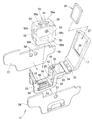
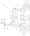
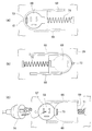
- FIG. 1 is a perspective view of an electric vehicle according to the present invention. It is a disassembled perspective view of the vehicle body principal part of this electric vehicle. It is sectional drawing of the bottom part of the battery accommodating part of this electric vehicle. It is sectional drawing of this electric power feeding terminal by the side of a vehicle body. It is sectional drawing of the latching mechanism of the vehicle-mounted battery of this electric vehicle. It is an effect
- the electric vehicle 10 includes a box-shaped vehicle body 11 including a front wheel 12 and a rear wheel 13, and a headlamp 14 and a left front turn signal 15 ⁇ / b> L (L is an attachment indicating the left) on the front surface of the vehicle body 11.
- L is an attachment indicating the left
- right front turn signal 15R R is a subscript indicating the right; the same applies hereinafter
- handle posts 16L and 16R are provided at the front of the upper surface of the vehicle body 11
- a seat 17 is provided at the rear of the upper surface of the vehicle body 11.
- This is an electric two-wheeled vehicle that is provided with upside down steps 18L and 18R on the side surface of the vehicle body 11 and is driven by an electric motor 20 built in the rear wheel 13.
- the left step 18L is drawn in a standing state (non-use state, storage state), and the right step 18R is drawn in a tilted state (use state).
- the driver sits on the seat 17, puts his / her feet on the steps 18L and 18R, holds the handle grip 19L above the left handle post 16L, holds the handle grip 19R above the right handle post 16R, and holds the right handle grip 19R.
- braking can be applied with the left and right brake levers 21L and 21R, and the rear can be visually recognized with the left and right rearview mirrors 22L and 22R.
- the vehicle width lights 23L and 23R outside the vehicle width of the handle grips 19L and 19R, the vehicle width is recognized outside.
- FIG. 2 is an exploded perspective view of the main part of the vehicle body 11.
- the vehicle body 11 includes a central frame 25 disposed in the center in the vehicle width direction, a left frame 26 along the left side surface of the central frame 25, and the central frame 25.
- the right side frame 27 along the right side of the main element is the main element.
- the central frame 25 includes a front wall portion 31, a bottom portion 32, a rear wall portion 33, and a container 34 provided continuously behind the rear wall portion 33 in the vehicle.
- the seat 17 can be attached to the rear portion of the container 34 via a hinge 35 so as to be opened and closed.
- the sheet 17 has a pocket portion 37 on the bottom surface (lower surface) in which the tablet terminal 36 is detachably stored.
- a terminal portion 38 is provided at one end of the pocket portion 37, and the tablet terminal 36 can be electrically connected to the vehicle body side.
- the tablet terminal 36 can also serve as an in-vehicle computer when traveling (details will be described later).
- the seat 17 can be opened and stood up as shown in the figure, so that it is possible to enjoy images and games like a television receiver. Alternatively, it can be used as a net information acquisition tool as a personal computer (personal computer).
- a plurality of leg storage recesses 39 are provided in the bottom 32, and these leg storage recesses 39 are connected by a communication groove 41.
- the vehicle body side power supply terminal 42 is disposed in a region surrounded by the leg storage recesses 39.
- a vertically long concave guide portion 43 is provided on the rear wall portion 33.
- the front wall portion 31 is also provided with a concave guide portion, it is not visible for convenience of illustration.
- a locking mechanism 44 is attached to the rear wall 33.
- the operation element 45 extends to the container 34.
- the operation element 45 is preferably arranged close to the right end or the left end of the container 34. With this arrangement, there is no concern that the operation element 45 will be in the way when an accessory is taken in and out of the container 34.
- the in-vehicle battery 50 is a relatively simple hexahedron, has a handle 51 on the upper surface 50a, has a vertically long convex portion 52 on the front surface 50b and the rear surface 50c, has a charging portion 53 on the left side surface 50d, and has a right side surface. 50e has discharge portions 54 and 55, and a battery-side power supply terminal 56 on the lower surface 50f.
- the in-vehicle battery 50 can be smoothly accommodated in the battery accommodating portion 28 by fitting the convex portion 52 to the concave guide portion 43 and lowering it. By fitting the convex portion 52 and the concave guide portion 43, the battery side power supply terminal 56 can be fitted to the vehicle body side power supply terminal 42 without shaking. Similarly, by fitting the convex portion 52 and the concave guide portion 43, the in-vehicle battery 50 can be pulled out without shaking.
- the convex portion 52 it is permissible to change the convex portion 52 to a concave portion.
- the concave guide portion 43 may be changed to a convex guide portion.
- the left side frame 26 is provided with a charging side opening 57 at a position corresponding to the charging unit 53 of the in-vehicle battery 50.
- the right frame 27 is provided with discharge-side openings 58 and 58 at positions corresponding to the discharge parts 54 and 55 of the in-vehicle battery 50.
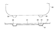
- a plurality of legs 59 protrude from the bottom of the in-vehicle battery 50. Since the plurality of legs 59 are provided, the in-vehicle battery 50 can be placed alone on the floor or on the road.
- a leg storage recess 39 is provided in the bottom 32 so that these legs 59 can be accommodated. Further, the leg storage recesses 39 are connected by a communication groove 41.
- a drain hole 61 is provided in one of the four leg storage recesses 39. The water collected in the other leg storage recesses 39 is collected in the leg storage recesses 39 through the communication grooves 41 and discharged outside the vehicle body through the drain holes 61.
- drain holes 61 it is permissible to provide the drain holes 61 in all the leg storage recesses 39.
- the drain hole 61 increases the risk that a part of the water in the puddle will enter the battery storage unit 28 through the drain hole 61 when the vehicle has plunged into the puddle.
- this embodiment since one drain hole 61 is provided for the four leg storage recesses 39, there is less concern about the backflow of water.
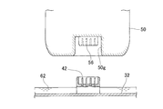
- a concave portion 50g corresponding to the vehicle body side power supply terminal 42 is provided on the in-vehicle battery 50 side, and a battery side power supply terminal 56 is provided in the concave portion 50g. Since the vehicle body side power supply terminal 42 protrudes to the information, the corresponding concave portion 50g is deepened. As a result, the concave portion 50g exhibits a guide action, and the battery side power supply terminal 56 is fitted to the vehicle body side power supply terminal 42 while being positioned more accurately.
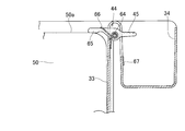
- the locking mechanism 44 includes a holding pawl 65 that is swingably stopped by a pin 64 on the upper portion of the rear wall portion 33, and an operating element 45 that extends from the holding pawl 65 and corresponds to a finger hooking portion. And a torsion spring 66 that urges the holding claw 65 so that the holding claw 65 strongly hits the upper surface of the in-vehicle battery 50.
- the operation element 45 extends to the container 34.
- a temporary fixing piece 67 for temporarily fixing the operating element 45 to the container 34 is rotatably provided.
- the charging side opening 57 provided in the left frame 26 and the discharge side opening 58 provided in the right frame 27 may be simple openings, but rainwater enters through these openings and the in-vehicle battery. If there are concerns about adverse effects on 50, it is necessary to take measures. The example of the countermeasure is described next.
- lid means that can be opened and closed at the charging side opening 57 provided in the left frame 26.
- Two examples of the shutter and the stopper as the lid means will be described in order.
- FIG. 8A is an enlarged view of the main part of FIG. 7, and FIG. 8B is a rear view of FIG. 8A.
- two L-section rails 68 and 68 are attached to the back surface (the surface on the vehicle body center side) of the left frame 26.
- a shutter 69 as a lid means is fitted between the two rails 68, 68, and the shutter 69 is urged toward the closing side by a compression spring 71.
- a stopper pin 72 is provided to stop the shutter 69 at the closed position.
- FIG. 8C which is an operation diagram of FIG. 8A
- a finger is placed on the finger-hooking piece 73 and the shutter 69 is moved to the open side.
- the charging side opening 57 is opened, and the charging unit 53 at the back is visible.
- a power supply plug 74 (or power supply connector) is inserted into the charging unit 53 to charge the in-vehicle battery.
- the shutter 69 is moved to the closed position by the action of the compression spring 71, and the charging side opening 57 is closed by the shutter 69 as shown in FIG.
- lid means that can be opened and closed at the discharge side openings 58 and 58 provided in the right frame 27 as well.
- plugs 76, 76 made of rubber or soft resin are fitted or covered on the discharge side openings 58, 58.
- FIG. 10B when the plug 76 is removed, the inner discharge portion 54 (or 55) can be seen.
- a power receiving plug 75 (or a power receiving connector) on the electric product side is connected to the discharge portion 54. It is desirable that the plug 76 is tied to the right frame 27 with a string-like member 77 such as a chain. This is because loss of the plug 76 can be prevented in advance.
- the plug 76 has a simple structure and is inexpensive. However, the string-like member 77 is an obstacle, and a part of the plug 76 protrudes from the frame 27.
- the lid means may be constituted by the plug 76, the shutter 69, or a closing member similar to these, and the type and form are arbitrary.
- FIG. 11 is a perspective view of the electric vehicle 10 as viewed from the rear, and a portable terminal 80 is provided between the left and right handle posts 16L and 16R.
- the portable terminal 80 includes a display unit 81 that displays a vehicle speed, a direction indication display, a storage amount, and other status displays, and a terminal body 82 that incorporates an arithmetic circuit and a memory. That is, the electric vehicle 10 does not include a meter unit in a fixed manner, and instead replaces the meter unit with the portable terminal 80.
- the in-vehicle battery 50 includes a battery body 85 and a transformers 86 and 87 in a battery case 84.
- One transformer 86 is a DC / DC converter that transforms a direct current into a direct current having a different voltage
- the other transformer 87 is a DC / AC inverter that converts a direct current 12V into an alternating current 100V, for example.
- a predetermined direct current for example, DC 24V
- the commercial power source AC 100V, 110V, 200V, 220V, etc.
- the electric power is supplied from the charging unit 53 to the electric motor 20 via the drive circuit 89 to travel.
- the rotation amount of the right handle grip 19R is detected by a sensor, and the information is sent to the portable terminal 80, and the driving circuit 89 is controlled by the command of the portable terminal 80 to adjust the traveling speed. Also good. Note that the rotation information of the right handle grip 19R may be sent directly to the drive circuit 89.
- the vehicle-mounted battery 50 can be used as a power source during non-running, for example, during outdoor camping.
- AC 100V (or AC 110V) can be received using one of the discharge portions 54 and used for rice cookers or lighting.
- the other discharge part 55 can be used to receive DC 12V and provide it to a personal computer.
- the in-vehicle battery 50 can receive power while being housed in the vehicle body, and can also receive power in a state where it is removed from the vehicle body, that is, the in-vehicle battery 50 alone.
- the power supply system a indicated by an imaginary line is extended from the transformer 86 and is electrically connected to the portable terminal 80 so that the portable terminal 80 is supplied with power constantly or at any time. As a result, it is possible to prevent a decrease in the remaining amount of electricity of the built-in battery built in the portable terminal 80.
- FIG. 13 is a diagram showing a modified example of FIG. 12, in which the drive circuit 89 in FIG. Others are the same as those in FIG. 12, and the detailed description is omitted by diverting the reference numerals.
- the power supply system b indicated by an imaginary line is extended from the transformer 87 and electrically connected to the tablet terminal 36 so that power is supplied to the tablet terminal 36 constantly or at any time. As a result, it is possible to prevent a decrease in the remaining amount of electricity of the built-in battery built in the tablet terminal 36.
- this invention was applied to the electric two-wheeled vehicle in embodiment, it can be applied also to an electric tricycle and can be applied to a general electric vehicle.
- the present invention is suitable for an electric motorcycle.
Landscapes
- Engineering & Computer Science (AREA)
- Mechanical Engineering (AREA)
- Chemical & Material Sciences (AREA)
- Power Engineering (AREA)
- Electrochemistry (AREA)
- General Chemical & Material Sciences (AREA)
- Chemical Kinetics & Catalysis (AREA)
- Transportation (AREA)
- Manufacturing & Machinery (AREA)
- Combustion & Propulsion (AREA)
- Sustainable Development (AREA)
- Life Sciences & Earth Sciences (AREA)
- Sustainable Energy (AREA)
- Aviation & Aerospace Engineering (AREA)
- Electric Propulsion And Braking For Vehicles (AREA)
- Arrangement Or Mounting Of Propulsion Units For Vehicles (AREA)
- Battery Mounting, Suspending (AREA)
- Charge And Discharge Circuits For Batteries Or The Like (AREA)
- Secondary Cells (AREA)
Abstract
Description
電動車両の車体に、前記車載バッテリを抜き差し可能に収納するバッテリ収納部が設けられ、このバッテリ収納部の底部に、前記車載バッテリの電力を車体側へ供給する車体側給電端子が設けられ、
前記車載バッテリには、下面に前記車体側給電端子に結合するバッテリ側給電端子が設けられ、車体左側と右側の一方に面する一方の側面に、外部電源から前記車載バッテリへ充填する充電部が設けられ、車体左側と右側の他方に面する他方の側面に、前記車載バッテリの電力を外部へ供給する放電部が設けられ、前記車載バッテリ内に、電力を変圧する及び/又は直流を交流に変換する変圧器が内蔵され、
前記車体の側面には、前記充電部に接続するプラグ又はコネクタを通過させる充電側開口部、及び前記放電部に接続するプラグ又はコネクタを通過させる放電側開口部が設けられていることを特徴とする。
非走行時に、電気製品のプラグやコネクタを放電部に接続することで、電気製品を使用することができる。
すなわち、車載バッテリは、走行時には電動機を駆動し、非走行時は外部の電気製品に電力を供給する。車載バッテリを、常時、使用することが可能となる。
本発明によれば、利用性が拡大された車載バッテリを備える電動車両が提供される。
車載バッテリ側の凸部(又は凹部)が、バッテリ収納部側の凹状ガイド部(又は凸状ガイド部)で案内されるため、車載バッテリの引き抜き及び挿入が、がたつくことなく円滑に行われる。併せて、位置決め性が良好であるため、バッテリ側給電端子を車体側給電端子に円滑に嵌めることができる。
この点、本発明によれば、蓋手段で雨水や埃の侵入を防ぐことができる。
物入れのスペースを利用し、このスペースに手を差し入れて操作子を操作することができる。係止機構の操作がより容易になる。
水抜き穴により、バッテリ収納部へ侵入した水を速やかに排出させることができる。浸水によりバッテリの劣化を防止することができる。
運転者は、シート17に座り、ステップ18L、18Rに足を載せ、左のハンドルポスト16L上部のハンドルグリップ19Lを握ると共に右のハンドルポスト16R上部のハンドルグリップ19Rを握り、右のハンドルグリップ19Rを回すことで、走り出すことができる。走行中は、左右のブレーキレバー21L、21Rで制動をかけ、左右のバックミラー22L、22Rで後方を視認することができる。ハンドルグリップ19L、19Rの車幅外側に車幅灯23L、23Rを設けることにより、外部に車幅を認識させる。
中央フレーム25は、バッテリ収納部28を構成する前壁部31、底部32、後壁部33と、この後壁部33の車両後方に連続して設けた物入れ34とからなる。この物入れ34の後部にヒンジ35を介してシート17を開閉可能に取付けることができる。
後壁部33に、縦長の凹状ガイド部43が設けられる。前壁部31にも凹状ガイド部が設けられるが、図示の都合で見えない。
凸部52を凹状ガイド部43に嵌め、下降させることで、車載バッテリ50をバッテリ収納部28に円滑に収納させることができる。凸部52と凹状ガイド部43の嵌合により、バッテリ側給電端子56は、振れることなく、車体側給電端子42に嵌めることができる。同様に、凸部52と凹状ガイド部43の嵌合により、振れることなく、車載バッテリ50を上へ抜くことができる。
右側フレーム27には、車載バッテリ50の放電部54、55に対応する位置に、放電側開口部58、58が設けられている。
これらの脚部59が収まるように底部32に脚収納凹部39が設けられている。さらに、脚収納凹部39間は連通溝41で結ばれている。4個のうちの1個の脚収納凹部39に水抜き穴61が設けられる。
他の脚収納凹部39に溜まった水は、連通溝41を介して脚収納凹部39に集められ、水抜き穴61を介して車体外へ排出される。
この点、この実施例では4個の脚収納凹部39に対して1個の水抜き穴61を設けたので、水が逆流する心配は少なくなる。
対策として、図4に示されるように、車体側給電端子42を底部32から上へ突出させる。この対策を講じることにより、少々の溜まり水62では車体側給電端子42が水に浸かる心配はなくなる。
図5に示されるように、係止機構44は、後壁部33の上部にピン64で揺動自在に止められる抑え爪65と、この抑え爪65から延びて指掛け部に相当する操作子45と、抑え爪65が車載バッテリ50の上面に強く当たるように抑え爪65を付勢するトーションばね66とからなる。
好ましくは、操作子45は物入れ34へ延ばす。加えて、物入れ34に操作子45を仮止めする仮止め片67を回転自在に設ける。
その対策の例を次に述べる。
図8(b)に示されるように、左側フレーム26の背面(車体中心側の面)に2本のL断面レール68、68を取付ける。2本のレール68、68間に、蓋手段としてのシャッタ69を嵌め、このシャッタ69を圧縮ばね71で閉じ側へ付勢する。好ましくは、閉じ位置でシャッタ69を制止するストッパピン72を立てる。
図10(b)に示されるように、栓76を外すと、奥の放電部54(又は55)が見える。この放電部54に電気製品側の受電プラグ75(又は受電コネクタ)を接続する。栓76は右側フレーム27に鎖などの紐状部材77で結んでおくことが望ましい。栓76の紛失を未然に防止することができるからである。
したがって、蓋手段は、栓76、シャッタ69又はこれらに類する閉じ部材で構成すればよく、種類、形式は任意である。
図11は電動車両10を後方から見た斜視図であり、左右のハンドルポスト16L、16R間に、携帯形端末80を備えている。この携帯形端末80は、車速速度、方向指示表示、蓄電量、その他の状態表示を行う表示部81と、演算回路及びメモリーを内蔵する端末本体82とからなる。すなわち、電動車両10は、メータユニットを固定的に備えていなく、代わりに携帯形端末80でメータユニットを代替する。
さらには、他方の放電部55を用いてDC12Vの供給を受け、パソコンに供することができる。
車載バッテリ50は、車体に収納したままで給電を受けることができる他、車体から外した状態、すなわち、車載バッテリ50単体でも給電を受けることができる。
Claims (7)
- 車体と、前記車体に搭載された車載バッテリと、前記車載バッテリから給電される電動機と、を備え、前記電動機の駆動力で走行する電動車両であって、
電動車両の車体に、前記車載バッテリを抜き差し可能に収納するバッテリ収納部が設けられ、このバッテリ収納部の底部に、前記車載バッテリの電力を車体側へ供給する車体側給電端子が設けられ、
前記車載バッテリには、下面に前記車体側給電端子に結合するバッテリ側給電端子が設けられ、車体左側と右側の一方に面する一方の側面に、外部電源から前記車載バッテリへ充填する充電部が設けられ、車体左側と右側の他方に面する他方の側面に、前記車載バッテリの電力を外部へ供給する放電部が設けられ、前記車載バッテリ内に、電力を変圧する及び/又は直流を交流に変換する変圧器が内蔵され、
前記車体の側面には、前記充電部に接続するプラグ又はコネクタを通過させる充電側開口部、及び前記放電部に接続するプラグ又はコネクタを通過させる放電側開口部が設けられている、ことを特徴とする電動車両。 - 前記車載バッテリの側面に凸部又は凹部が設けられ、前記バッテリ収納部に前記凸部又は前記凹部を案内する凹状ガイド部又は凸状ガイド部が設けられている、請求項1記載の電動車両。
- 前記バッテリ収納部に、これに収納された前記車載バッテリが抜けることを防止する係止機構が付設されている、請求項1又は2記載の電動車両。
- 前記車体側給電端子は、前記バッテリ収納部の底部から上方へ突出して設けられている、請求項1記載の電動車両。
- 前記充電側開口部及び前記放電側開口部は、開閉可能な蓋手段で塞がれている、請求項1記載の電動車両。
- 前記バッテリ収納部には、車体後方位置に物入れが付設され、この物入れに前記係止機構の操作子が収納されている、請求項3記載の電動車両。
- 前記バッテリ収納部の底部に、水抜き穴が設けられている、請求項1記載の電動車両。
Priority Applications (7)
| Application Number | Priority Date | Filing Date | Title |
|---|---|---|---|
| EP12844248.0A EP2772420B1 (en) | 2011-10-26 | 2012-10-19 | Electric vehicle |
| JP2013540751A JP5728591B2 (ja) | 2011-10-26 | 2012-10-19 | 電動車両 |
| US14/348,685 US9481249B2 (en) | 2011-10-26 | 2012-10-19 | Electric vehicle |
| AU2012330172A AU2012330172B2 (en) | 2011-10-26 | 2012-10-19 | Electric vehicle |
| CN201280050713.8A CN103874624B (zh) | 2011-10-26 | 2012-10-19 | 电动车辆 |
| ES12844248.0T ES2613764T3 (es) | 2011-10-26 | 2012-10-19 | Vehículo eléctrico |
| CA2852195A CA2852195C (en) | 2011-10-26 | 2012-10-19 | Electric vehicle |
Applications Claiming Priority (2)
| Application Number | Priority Date | Filing Date | Title |
|---|---|---|---|
| JP2011235070 | 2011-10-26 | ||
| JP2011-235070 | 2011-10-26 |
Publications (1)
| Publication Number | Publication Date |
|---|---|
| WO2013061880A1 true WO2013061880A1 (ja) | 2013-05-02 |
Family
ID=48167712
Family Applications (1)
| Application Number | Title | Priority Date | Filing Date |
|---|---|---|---|
| PCT/JP2012/077094 Ceased WO2013061880A1 (ja) | 2011-10-26 | 2012-10-19 | 電動車両 |
Country Status (9)
| Country | Link |
|---|---|
| US (1) | US9481249B2 (ja) |
| EP (1) | EP2772420B1 (ja) |
| JP (1) | JP5728591B2 (ja) |
| CN (1) | CN103874624B (ja) |
| AU (1) | AU2012330172B2 (ja) |
| CA (1) | CA2852195C (ja) |
| ES (1) | ES2613764T3 (ja) |
| TW (1) | TWI507321B (ja) |
| WO (1) | WO2013061880A1 (ja) |
Cited By (11)
| Publication number | Priority date | Publication date | Assignee | Title |
|---|---|---|---|---|
| ITTV20130078A1 (it) * | 2013-05-23 | 2014-11-24 | Estrima Srl | "sistema contenitore di batteria d'alimentazione rimovibile a scorrimento da un alloggiamento di almeno un lato di un veicolo elettrico, provvisto di mezzi di connessione elettrici, trolley su ruote con maniglia telescopica e rampa pieghevole". |
| JP2016038983A (ja) * | 2014-08-06 | 2016-03-22 | 本田技研工業株式会社 | バッテリパック及び電動車両 |
| JP2017055577A (ja) * | 2015-09-10 | 2017-03-16 | 株式会社アクティオ | 工事用作業車および電源装置 |
| JP2018037203A (ja) * | 2016-08-30 | 2018-03-08 | 株式会社豊田自動織機 | 電池パック設置構造 |
| JP2018037210A (ja) * | 2016-08-30 | 2018-03-08 | 株式会社豊田自動織機 | 電池パック及び充電口ユニット |
| TWI677455B (zh) * | 2017-09-08 | 2019-11-21 | 日商新電元工業股份有限公司 | 電動車輛、電動車輛控制裝置及電動車輛控制方法 |
| JP2020135941A (ja) * | 2019-02-13 | 2020-08-31 | 株式会社オートネットワーク技術研究所 | コネクタ装置 |
| JP2020142771A (ja) * | 2019-03-08 | 2020-09-10 | 本田技研工業株式会社 | 電動車両のバッテリ端子構造 |
| JP2022083184A (ja) * | 2020-11-24 | 2022-06-03 | スズキ株式会社 | バッテリ |
| WO2023100445A1 (ja) * | 2021-12-01 | 2023-06-08 | 本田技研工業株式会社 | 収容装置 |
| WO2024048544A1 (ja) * | 2022-08-30 | 2024-03-07 | 本田技研工業株式会社 | 車両 |
Families Citing this family (36)
| Publication number | Priority date | Publication date | Assignee | Title |
|---|---|---|---|---|
| EP2796352B1 (en) * | 2011-12-22 | 2021-03-03 | Yamaha Hatsudoki Kabushiki Kaisha | Saddled electric vehicle |
| EP2799320B1 (en) * | 2011-12-28 | 2020-11-18 | Kawasaki Jukogyo Kabushiki Kaisha | Electric straddled vehicle |
| FR3008041B1 (fr) * | 2013-07-05 | 2016-12-09 | Blue Solutions | Vehicule electrique et installation de transport associee |
| JP2015089756A (ja) * | 2013-11-06 | 2015-05-11 | ヤマハ発動機株式会社 | 鞍乗型電動車両 |
| US9914501B2 (en) * | 2014-03-18 | 2018-03-13 | Askoll Eva S.R.L. | Battery holder device for electric bicycle |
| US10730584B2 (en) | 2014-09-11 | 2020-08-04 | Stacyc, Inc. | Convertible motorized running cycle |
| US9937975B2 (en) * | 2014-09-11 | 2018-04-10 | REP Concepts, Inc. | Convertible motorized running cycle |
| TWI629185B (zh) * | 2015-06-02 | 2018-07-11 | 光陽工業股份有限公司 | 機車之電池蓋裝置 |
| WO2017022394A1 (ja) * | 2015-07-31 | 2017-02-09 | 本田技研工業株式会社 | 電動車両 |
| WO2018033880A2 (en) | 2016-08-17 | 2018-02-22 | Shape Corp. | Battery support and protection structure for a vehicle |
| EP3309001B1 (en) * | 2016-10-14 | 2021-09-29 | EP Equipment Co., Ltd. | Battery plug-in device for material handling equipment |
| WO2018085411A1 (en) | 2016-11-04 | 2018-05-11 | Black & Decker Inc. | Total task vehicle |
| DE102016123553A1 (de) * | 2016-12-06 | 2018-06-07 | Dr. Ing. H.C. F. Porsche Aktiengesellschaft | Fahrzeugkarosserie für ein elektrisch angetriebenes Fahrzeug |
| EP3566253B1 (en) | 2017-01-04 | 2022-12-28 | Shape Corp. | Battery support structure for a vehicle |
| CN106926731B (zh) * | 2017-04-02 | 2019-05-31 | 芬华氢能研究院江苏有限公司 | 一种新能源汽车电池管理系统及方法 |
| US10483510B2 (en) | 2017-05-16 | 2019-11-19 | Shape Corp. | Polarized battery tray for a vehicle |
| WO2018213383A1 (en) | 2017-05-16 | 2018-11-22 | Shape Corp. | Vehicle battery tray with integrated battery retention and support features |
| US10886513B2 (en) | 2017-05-16 | 2021-01-05 | Shape Corp. | Vehicle battery tray having tub-based integration |
| US12347879B2 (en) | 2017-09-13 | 2025-07-01 | Shape Corp. | Vehicle battery tray with tubular peripheral wall |
| WO2019055658A2 (en) | 2017-09-13 | 2019-03-21 | Shape Corp. | VEHICLE BATTERY TRAY WITH TUBULAR PERIPHERAL WALL |
| JP6874144B2 (ja) * | 2017-09-29 | 2021-05-19 | 本田技研工業株式会社 | 電動車両のバッテリ収納装置 |
| DE112018005556T5 (de) | 2017-10-04 | 2020-06-25 | Shape Corp. | Batterieträger-bodenbaugruppe für elektrofahrzeuge |
| TWI663089B (zh) * | 2018-01-31 | 2019-06-21 | 光陽工業股份有限公司 | 電動車輛的電池盒鎖定裝置 |
| WO2019169080A1 (en) | 2018-03-01 | 2019-09-06 | Shape Corp. | Cooling system integrated with vehicle battery tray |
| US11688910B2 (en) | 2018-03-15 | 2023-06-27 | Shape Corp. | Vehicle battery tray having tub-based component |
| EP3778360B1 (en) * | 2018-03-29 | 2024-08-14 | Honda Motor Co., Ltd. | Usb terminal unit arrangement structure for saddle riding-type vehicle |
| JP6708712B2 (ja) * | 2018-08-20 | 2020-06-10 | 本田技研工業株式会社 | 鞍乗型車両 |
| JP7323496B2 (ja) * | 2020-08-21 | 2023-08-08 | トヨタ自動車株式会社 | 電動車両 |
| CN114335916A (zh) * | 2020-09-30 | 2022-04-12 | 广州市凯捷电源实业有限公司 | 一种蓄电池 |
| US11603165B2 (en) | 2021-03-04 | 2023-03-14 | StaCyc, LLC | Bike frame having a drive module enclosure |
| WO2023039558A1 (en) * | 2021-09-10 | 2023-03-16 | Land Energy, Inc | Electric vehicle with a battery module and a battery receiver |
| US20230083352A1 (en) * | 2021-09-10 | 2023-03-16 | Land Energy, Inc | Hot swap battery pack |
| USD1022804S1 (en) | 2021-12-13 | 2024-04-16 | StaCyc, LLC | Electric bicycle |
| JP7464577B2 (ja) * | 2021-12-24 | 2024-04-09 | ヤマハ発動機株式会社 | 駆動ユニット及び駆動ユニットのカバー |
| US12565277B2 (en) | 2023-02-09 | 2026-03-03 | StaCyc, LLC | Battery support frame for a bicycle |
| US20250282439A1 (en) * | 2024-03-05 | 2025-09-11 | Honda Motor Co., Ltd. | Electric vehicle frame for mounting high-capacity battery |
Citations (8)
| Publication number | Priority date | Publication date | Assignee | Title |
|---|---|---|---|---|
| JPH0585362A (ja) * | 1991-09-25 | 1993-04-06 | Shinko Electric Co Ltd | 自走式一輪電源車 |
| JPH11129960A (ja) * | 1997-11-04 | 1999-05-18 | Honda Motor Co Ltd | 電動補助車両用バッテリユニット |
| JP2000033893A (ja) * | 1998-05-11 | 2000-02-02 | Miyata Ind Co Ltd | 電動アシスト自転車用車載式充電装置 |
| JP3683307B2 (ja) | 1995-06-30 | 2005-08-17 | ヤマハ発動機株式会社 | 車両用バッテリ収納装置 |
| JP2007209188A (ja) * | 2006-02-01 | 2007-08-16 | Ikedo Yosetsu Seisakusho:Kk | 発電機移送用車両 |
| JP2009040087A (ja) * | 2007-08-06 | 2009-02-26 | Suzuki Motor Corp | 車両用荷物収納ボックス構造 |
| WO2011024326A1 (ja) * | 2009-08-31 | 2011-03-03 | 本田技研工業株式会社 | 充電器、及び充電器の取付け構造 |
| JP2011136626A (ja) * | 2009-12-28 | 2011-07-14 | Honda Motor Co Ltd | 鞍乗型電動車両 |
Family Cites Families (20)
| Publication number | Priority date | Publication date | Assignee | Title |
|---|---|---|---|---|
| JP2623050B2 (ja) * | 1992-05-26 | 1997-06-25 | ヤマハ発動機株式会社 | 電動自転車用バッテリーケースの取付構造 |
| JP3231550B2 (ja) * | 1994-06-11 | 2001-11-26 | 本田技研工業株式会社 | 電動補助自転車のボデイカバー構造 |
| EP1180477A3 (en) * | 1994-11-18 | 2002-06-19 | Yamaha Hatsudoki Kabushiki Kaisha | Battery holding structure for a vehicle |
| JP3491708B2 (ja) * | 1995-02-23 | 2004-01-26 | ヤマハ発動機株式会社 | 電動自転車用バッテリ収納装置 |
| JP3622020B2 (ja) * | 1996-07-31 | 2005-02-23 | ヤマハ発動機株式会社 | 電動自転車のバッテリボックス脱着構造 |
| JP3676225B2 (ja) * | 2000-11-30 | 2005-07-27 | 三洋電機株式会社 | 電動の乗り物用の電池パック |
| JP2003127941A (ja) * | 2001-10-19 | 2003-05-08 | Yamaha Motor Co Ltd | 電動二輪車のバッテリ脱着構造 |
| JP4274759B2 (ja) * | 2002-08-16 | 2009-06-10 | ヤマハ発動機株式会社 | 電動二輪車 |
| CN2874781Y (zh) * | 2005-07-08 | 2007-02-28 | 张胜祥 | 电动车的电池盒 |
| US7388348B2 (en) * | 2005-07-15 | 2008-06-17 | Mattichak Alan D | Portable solar energy system |
| TWM314136U (en) * | 2007-01-08 | 2007-06-21 | Wus Tech Co Ltd | Improved structure for positioning battery of powered wheelchair |
| JP5071711B2 (ja) * | 2007-07-20 | 2012-11-14 | 本田技研工業株式会社 | 鞍乗型電動車両 |
| TWM331761U (en) * | 2007-10-31 | 2008-05-01 | Motive Power Industry Co Ltd | Automatic locking and fastening device for battery box |
| JP2009132860A (ja) * | 2007-11-07 | 2009-06-18 | Hitachi Chem Co Ltd | 樹脂組成物及びこれを用いた膜状光学部材 |
| CN201117697Y (zh) * | 2007-11-13 | 2008-09-17 | 摩特动力工业股份有限公司 | 旋转收纳结构的电池盒 |
| DE102008024007B4 (de) * | 2008-05-17 | 2013-12-05 | Oliver Luithle | Akkumulator-Einheit und damit ausgestattetes Elektrofahrzeug |
| JP4577413B2 (ja) * | 2008-06-20 | 2010-11-10 | トヨタ自動車株式会社 | 車両 |
| JP5593894B2 (ja) * | 2009-07-30 | 2014-09-24 | スズキ株式会社 | 電動の乗り物に脱着されるバッテリパックとこのバッテリパックを備える電動の乗り物 |
| JP5417104B2 (ja) * | 2009-09-28 | 2014-02-12 | 本田技研工業株式会社 | 鞍乗り型車両のバッテリ周辺構造 |
| JP5786568B2 (ja) * | 2011-09-01 | 2015-09-30 | ソニー株式会社 | 蓄電装置および蓄電システム |
-
2012
- 2012-10-19 JP JP2013540751A patent/JP5728591B2/ja not_active Expired - Fee Related
- 2012-10-19 EP EP12844248.0A patent/EP2772420B1/en not_active Not-in-force
- 2012-10-19 CA CA2852195A patent/CA2852195C/en not_active Expired - Fee Related
- 2012-10-19 CN CN201280050713.8A patent/CN103874624B/zh not_active Expired - Fee Related
- 2012-10-19 WO PCT/JP2012/077094 patent/WO2013061880A1/ja not_active Ceased
- 2012-10-19 ES ES12844248.0T patent/ES2613764T3/es active Active
- 2012-10-19 US US14/348,685 patent/US9481249B2/en not_active Expired - Fee Related
- 2012-10-19 AU AU2012330172A patent/AU2012330172B2/en not_active Ceased
- 2012-10-24 TW TW101139250A patent/TWI507321B/zh not_active IP Right Cessation
Patent Citations (8)
| Publication number | Priority date | Publication date | Assignee | Title |
|---|---|---|---|---|
| JPH0585362A (ja) * | 1991-09-25 | 1993-04-06 | Shinko Electric Co Ltd | 自走式一輪電源車 |
| JP3683307B2 (ja) | 1995-06-30 | 2005-08-17 | ヤマハ発動機株式会社 | 車両用バッテリ収納装置 |
| JPH11129960A (ja) * | 1997-11-04 | 1999-05-18 | Honda Motor Co Ltd | 電動補助車両用バッテリユニット |
| JP2000033893A (ja) * | 1998-05-11 | 2000-02-02 | Miyata Ind Co Ltd | 電動アシスト自転車用車載式充電装置 |
| JP2007209188A (ja) * | 2006-02-01 | 2007-08-16 | Ikedo Yosetsu Seisakusho:Kk | 発電機移送用車両 |
| JP2009040087A (ja) * | 2007-08-06 | 2009-02-26 | Suzuki Motor Corp | 車両用荷物収納ボックス構造 |
| WO2011024326A1 (ja) * | 2009-08-31 | 2011-03-03 | 本田技研工業株式会社 | 充電器、及び充電器の取付け構造 |
| JP2011136626A (ja) * | 2009-12-28 | 2011-07-14 | Honda Motor Co Ltd | 鞍乗型電動車両 |
Non-Patent Citations (1)
| Title |
|---|
| See also references of EP2772420A4 |
Cited By (16)
| Publication number | Priority date | Publication date | Assignee | Title |
|---|---|---|---|---|
| ITTV20130078A1 (it) * | 2013-05-23 | 2014-11-24 | Estrima Srl | "sistema contenitore di batteria d'alimentazione rimovibile a scorrimento da un alloggiamento di almeno un lato di un veicolo elettrico, provvisto di mezzi di connessione elettrici, trolley su ruote con maniglia telescopica e rampa pieghevole". |
| JP2016038983A (ja) * | 2014-08-06 | 2016-03-22 | 本田技研工業株式会社 | バッテリパック及び電動車両 |
| JP2017055577A (ja) * | 2015-09-10 | 2017-03-16 | 株式会社アクティオ | 工事用作業車および電源装置 |
| JP2018037203A (ja) * | 2016-08-30 | 2018-03-08 | 株式会社豊田自動織機 | 電池パック設置構造 |
| JP2018037210A (ja) * | 2016-08-30 | 2018-03-08 | 株式会社豊田自動織機 | 電池パック及び充電口ユニット |
| TWI677455B (zh) * | 2017-09-08 | 2019-11-21 | 日商新電元工業股份有限公司 | 電動車輛、電動車輛控制裝置及電動車輛控制方法 |
| CN113424372A (zh) * | 2019-02-13 | 2021-09-21 | 株式会社自动网络技术研究所 | 连接器装置 |
| JP2020135941A (ja) * | 2019-02-13 | 2020-08-31 | 株式会社オートネットワーク技術研究所 | コネクタ装置 |
| JP7247629B2 (ja) | 2019-02-13 | 2023-03-29 | 株式会社オートネットワーク技術研究所 | コネクタ装置 |
| JP2020142771A (ja) * | 2019-03-08 | 2020-09-10 | 本田技研工業株式会社 | 電動車両のバッテリ端子構造 |
| JP2022083184A (ja) * | 2020-11-24 | 2022-06-03 | スズキ株式会社 | バッテリ |
| JP7581793B2 (ja) | 2020-11-24 | 2024-11-13 | スズキ株式会社 | バッテリ |
| WO2023100445A1 (ja) * | 2021-12-01 | 2023-06-08 | 本田技研工業株式会社 | 収容装置 |
| JPWO2023100445A1 (ja) * | 2021-12-01 | 2023-06-08 | ||
| JP7736810B2 (ja) | 2021-12-01 | 2025-09-09 | 本田技研工業株式会社 | 収容装置 |
| WO2024048544A1 (ja) * | 2022-08-30 | 2024-03-07 | 本田技研工業株式会社 | 車両 |
Also Published As
| Publication number | Publication date |
|---|---|
| JP5728591B2 (ja) | 2015-06-03 |
| CA2852195C (en) | 2016-04-19 |
| US20140319907A1 (en) | 2014-10-30 |
| CA2852195A1 (en) | 2013-05-02 |
| TWI507321B (zh) | 2015-11-11 |
| EP2772420A4 (en) | 2015-06-10 |
| ES2613764T3 (es) | 2017-05-25 |
| AU2012330172A1 (en) | 2014-04-17 |
| CN103874624A (zh) | 2014-06-18 |
| EP2772420B1 (en) | 2016-11-30 |
| AU2012330172B2 (en) | 2015-07-16 |
| EP2772420A1 (en) | 2014-09-03 |
| US9481249B2 (en) | 2016-11-01 |
| CN103874624B (zh) | 2016-08-17 |
| TW201331091A (zh) | 2013-08-01 |
| JPWO2013061880A1 (ja) | 2015-04-02 |
Similar Documents
| Publication | Publication Date | Title |
|---|---|---|
| JP5728591B2 (ja) | 電動車両 | |
| TWI546211B (zh) | 充電器及充電器之安裝構造 | |
| CN102627133B (zh) | 两轮电动车 | |
| EP2479094B1 (en) | Electrically driven two-wheeled vehicle | |
| JP5197563B2 (ja) | 鞍乗型電動車両 | |
| JP5456623B2 (ja) | 充電器 | |
| WO2012085977A1 (ja) | 電動二輪車 | |
| JP2011063074A (ja) | 電動二輪車 | |
| CN102642477A (zh) | 电动车辆 | |
| CN103072654B (zh) | 电动车辆 | |
| JP5576536B2 (ja) | 充電器 | |
| CN111422292B (zh) | 跨骑型车辆 | |
| JP5421995B2 (ja) | 充電器の取付け構造 | |
| JP5767943B2 (ja) | 電動車両 | |
| JPWO2020129643A1 (ja) | 鞍乗型車両 | |
| JP5461123B2 (ja) | 自動二輪車 | |
| CN113195347A (zh) | 跨骑型车辆 |
Legal Events
| Date | Code | Title | Description |
|---|---|---|---|
| 121 | Ep: the epo has been informed by wipo that ep was designated in this application |
Ref document number: 12844248 Country of ref document: EP Kind code of ref document: A1 |
|
| ENP | Entry into the national phase |
Ref document number: 2013540751 Country of ref document: JP Kind code of ref document: A |
|
| WWE | Wipo information: entry into national phase |
Ref document number: 14348685 Country of ref document: US |
|
| ENP | Entry into the national phase |
Ref document number: 2852195 Country of ref document: CA |
|
| ENP | Entry into the national phase |
Ref document number: 2012330172 Country of ref document: AU Date of ref document: 20121019 Kind code of ref document: A |
|
| NENP | Non-entry into the national phase |
Ref country code: DE |
|
| REEP | Request for entry into the european phase |
Ref document number: 2012844248 Country of ref document: EP |
|
| WWE | Wipo information: entry into national phase |
Ref document number: 2012844248 Country of ref document: EP |