WO2013073155A1 - Téléobjectif moyen et dispositif imageur - Google Patents
Téléobjectif moyen et dispositif imageur Download PDFInfo
- Publication number
- WO2013073155A1 WO2013073155A1 PCT/JP2012/007239 JP2012007239W WO2013073155A1 WO 2013073155 A1 WO2013073155 A1 WO 2013073155A1 JP 2012007239 W JP2012007239 W JP 2012007239W WO 2013073155 A1 WO2013073155 A1 WO 2013073155A1
- Authority
- WO
- WIPO (PCT)
- Prior art keywords
- lens
- medium telephoto
- positive
- object side
- focal length
- Prior art date
- Legal status (The legal status is an assumption and is not a legal conclusion. Google has not performed a legal analysis and makes no representation as to the accuracy of the status listed.)
- Ceased
Links
Images





Classifications
-
- G—PHYSICS
- G02—OPTICS
- G02B—OPTICAL ELEMENTS, SYSTEMS OR APPARATUS
- G02B13/00—Optical objectives specially designed for the purposes specified below
- G02B13/02—Telephoto objectives, i.e. systems of the type + - in which the distance from the front vertex to the image plane is less than the equivalent focal length
-
- G—PHYSICS
- G02—OPTICS
- G02B—OPTICAL ELEMENTS, SYSTEMS OR APPARATUS
- G02B13/00—Optical objectives specially designed for the purposes specified below
- G02B13/18—Optical objectives specially designed for the purposes specified below with lenses having one or more non-spherical faces, e.g. for reducing geometrical aberration
Definitions
- the present invention relates to a medium telephoto lens suitable for an image pickup apparatus such as a single-lens reflex camera, and more particularly to a medium telephoto lens suitable for short-distance shooting and an image pickup apparatus including the medium telephoto lens.
- Patent Documents 1 and 2 Conventionally, as this type of medium telephoto lens, as shown in Patent Documents 1 and 2, a first lens group and a second lens group are arranged in order from the object side. What moves both is known. However, since the medium telephoto lenses described in Patent Documents 1 and 2 employ a floating mechanism that moves both the first lens group and the second lens group, the mechanism for moving the lens becomes complicated. This increases the size of the lens and increases the cost.
- Patent Document 3 a medium telephoto lens in which only the first lens group is moved during focusing is also known.
- the medium telephoto lens described in Patent Document 3 includes, in order from the object side, a first lens group having a positive refractive index as a whole and a second lens group having a positive refractive index as a whole.
- a positive 1-1 lens having a stronger positive power on the object side surface a 1-2 lens consisting of a positive meniscus lens having a positive power on the object side surface, image side 1-3 lens composed of a negative meniscus lens with a concave surface facing the aperture, a stop, a cemented lens of a negative first lens with a concave surface facing the object side and a positive first 1-5 lens, and a positive first lens
- the second lens group is composed of, in order from the object side, a 2-1 lens composed of a negative meniscus lens having a convex surface directed toward the object side, and a positive 2-2 lens. Only the first lens group is in the optical axis direction It is adapted to move.
- the present invention has been made in view of the above circumstances, and provides a medium telephoto lens that has less chromatic aberration, can be reduced in size, cost, and performance, and an imaging apparatus including the medium telephoto lens. It is intended.
- the middle telephoto lens according to the present invention includes a first lens group having a positive refractive power and a second lens group in order from the object side, and the first lens group has a convex surface directed toward the object side in order from the object side.
- the 1-3 lens and the 1-4 lens are cemented, the 1-5 lens and the 1-6 lens are cemented,
- the second lens group includes, in order from the object side, a negative 2-1 lens having a concave surface facing the image side, and a positive 2-2 lens having a convex surface facing the object side, In focusing, only the first lens group moves in the optical axis direction.
- the medium telephoto lens of the present invention is composed of a first lens group and a second lens group.
- a lens having substantially no power a lens such as an aperture or a cover glass.
- Other optical elements, lens flanges, lens barrels, image sensors, and those having a mechanism portion such as a camera shake correction mechanism may also be included.
- the lens surface shape such as convex surface, concave surface, plane, biconcave, meniscus, biconvex, plano-convex and plano-concave, and the sign of the refractive power of the lens such as positive and negative include aspherical surfaces. Unless otherwise noted, the paraxial region is considered. In the present invention, the sign of the radius of curvature is positive when the surface shape is convex on the object side and negative when the surface shape is convex on the image side.
- the second lens group includes, in order from the object side, a negative 2-1 lens having a concave surface facing the image side, and a positive second lens having a convex surface facing the object side.
- -2 lens and a positive second-3 lens having a convex surface facing the image side are preferable.
- the first to seventh lenses are aspherical lenses each having at least one aspherical surface.
- conditional expressions (1) to (5) are satisfied.
- it may have any one of the following conditional expressions (1) to (5), or may have a structure in which any two or more are combined.
- An image pickup apparatus includes the above-described medium telephoto lens according to the present invention.
- the first and third lenses constituting the first lens group are cemented, and only the first lens group moves in the optical axis direction during focusing. It is possible to achieve good resolution performance with little change from far to short distances, and to achieve downsizing of the lens and simplification of the focus mechanism, thereby realizing a high performance medium telephoto lens.
- the image pickup apparatus of the present invention since the medium telephoto lens of the present invention is provided, the image pickup apparatus can be configured to be small and inexpensive, and a good image with high resolution can be obtained using the image sensor.
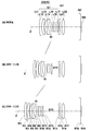
- FIG. 1 is a lens cross-sectional view illustrating a first configuration example of a medium telephoto lens according to an embodiment of the present invention and corresponding to Numerical Example 1.
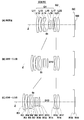
- FIG. 9 is a lens cross-sectional view illustrating a second configuration example of the medium telephoto lens and corresponding to Numerical Example 2.
- FIG. 9 is a lens cross-sectional view illustrating a third configuration example of the middle telephoto lens and corresponding to Numerical Example 3.
- FIG. 7 is a lens cross-sectional view illustrating a fourth configuration example of a medium telephoto lens and corresponding to Numerical Example 4; 10 is a lens cross-sectional view illustrating a fifth configuration example of the intermediate telephoto lens and corresponding to Numerical Example 5.
- FIG. 9 is a lens cross-sectional view illustrating a second configuration example of the medium telephoto lens and corresponding to Numerical Example 2.
- FIG. 9 is a lens cross-sectional view illustrating a third configuration example of the middle telephoto
- FIG. 6 is a lens cross-sectional view illustrating a sixth configuration example of the intermediate telephoto lens and corresponding to Numerical Example 6.
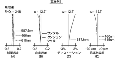
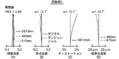
- FIG. FIG. 4 is a diagram illustrating various aberrations of the medium telephoto lens according to Example 1 in an infinitely focused state, where (A) shows spherical aberration, (B) shows astigmatism, (C) shows distortion, and (D) shows chromatic aberration of magnification. .
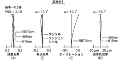
- FIG. 4 is a diagram illustrating various aberrations of the medium telephoto lens according to Example 1 in a focusing state of 0.2 ⁇ , where (A) is spherical aberration, (B) is astigmatism, (C) is distortion, (D ) Indicates lateral chromatic aberration.
- FIG. 6 is a diagram illustrating various aberrations of the medium telephoto lens according to Example 1 in a focusing state of ⁇ 0.5 ⁇ , where (A) is spherical aberration, (B) is astigmatism, (C) is distortion, (D ) Indicates lateral chromatic aberration.
- FIG. 6 is a diagram illustrating various aberrations of the medium telephoto lens according to Example 2 in an infinite focus state, where (A) shows spherical aberration, (B) shows astigmatism, (C) shows distortion, and (D) shows chromatic aberration of magnification. .
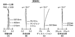
- FIG. 6A is a diagram illustrating various aberrations of the medium telephoto lens according to Example 2 in an in-focus state at an imaging magnification of ⁇ 0.2 ⁇ , where (A) is spherical aberration, (B) is astigmatism, (C) is distortion, (D ) Indicates lateral chromatic aberration.
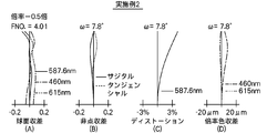
- FIG. 6A is a diagram illustrating various aberrations of the medium telephoto lens according to Example 2 when the photographing magnification is ⁇ 0.5 times, in which (A) is spherical aberration, (B) is astigmatism, (C) is distortion, (D ) Indicates lateral chromatic aberration.
- FIG. 6A is a diagram illustrating various aberrations of the medium telephoto lens according to Example 2 when the photographing magnification is ⁇ 0.5 times, in which (A) is spherical aberration, (B) is astigmatism, (C) is distortion, (D ) Indicates lateral chromatic aberration
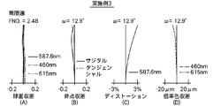
- FIG. 6 is a diagram showing various aberrations of the medium telephoto lens according to Example 3 in an infinitely focused state, where (A) shows spherical aberration, (B) shows astigmatism, (C) shows distortion, and (D) shows chromatic aberration of magnification.
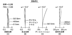
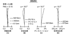
- FIG. 6A is a diagram illustrating various aberrations of the medium telephoto lens according to Example 3 in an in-focus state at a photographing magnification of ⁇ 0.2 ⁇ , where (A) is spherical aberration, (B) is astigmatism, (C) is distortion, (D ) Indicates lateral chromatic aberration.
- FIG. 6A is a diagram showing various aberrations of the medium telephoto lens according to Example 3 in an infinitely focused state, where (A) shows spherical aberration, (B) shows astigmatism, (C) shows distortion, and (D) shows chromatic aberration of magnification.
- FIG. 6A is a diagram illustrating various aber
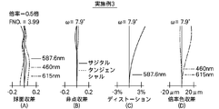
- FIG. 7A is a diagram illustrating various aberrations of the medium telephoto lens according to Example 3 in a focusing state of ⁇ 0.5 ⁇ , where (A) is spherical aberration, (B) is astigmatism, (C) is distortion, (D ) Indicates lateral chromatic aberration.
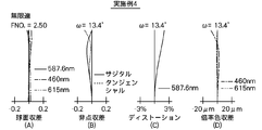
- FIG. 7A is a diagram illustrating various aberrations of the medium telephoto lens according to Example 4 in an infinitely focused state, where (A) shows spherical aberration, (B) shows astigmatism, (C) shows distortion, and (D) shows chromatic aberration of magnification. .
- FIG. 1 shows spherical aberration
- B shows astigmatism
- C shows distortion
- D shows chromatic aberration of magnification.
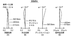
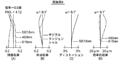
- FIG. 9A is a diagram illustrating various aberrations of the medium telephoto lens according to Example 4 in an in-focus state at a photographing magnification of ⁇ 0.2 ⁇ , where (A) is spherical aberration, (B) is astigmatism, (C) is distortion, (D ) Indicates lateral chromatic aberration.
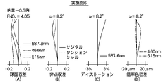
- FIG. 9A is a diagram illustrating various aberrations of the medium telephoto lens according to Example 4 in a focusing state of ⁇ 0.5 ⁇ , where (A) is spherical aberration, (B) is astigmatism, (C) is distortion, (D ) Indicates lateral chromatic aberration.
- FIG. 9A is a diagram illustrating various aberrations of the medium telephoto lens according to Example 4 in a focusing state of ⁇ 0.5 ⁇ , where (A) is spherical aberration, (B) is astigmatism, (C) is distortion, (D ) Indicates lateral chromatic aberration
- FIG. 10 is a diagram illustrating various aberrations of the middle telephoto lens according to Example 5 in an infinite focus state, where (A) shows spherical aberration, (B) shows astigmatism, (C) shows distortion, and (D) shows chromatic aberration of magnification.
- FIG. 10A is a diagram illustrating various aberrations of the medium telephoto lens according to Example 5 in a focusing state of 0.2 ⁇ , where (A) is spherical aberration, (B) is astigmatism, (C) is distortion, (D ) Indicates lateral chromatic aberration.
- FIG. 10A is a diagram illustrating various aberrations of the middle telephoto lens according to Example 5 in an infinite focus state, where (A) shows spherical aberration, (B) shows astigmatism, (C) shows distortion, and (D) shows chromatic aberration of magnification.
- FIG. 10A is a diagram illustrating various aberrations of the medium telephoto lens
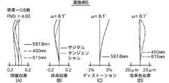
- FIG. 7A is a diagram illustrating various aberrations of the medium telephoto lens according to Example 5 in an in-focus state at a photographing magnification of ⁇ 0.5, where (A) is spherical aberration, (B) is astigmatism, (C) is distortion, (D ) Indicates lateral chromatic aberration.
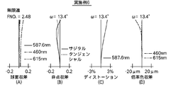
- FIG. 10 is a diagram illustrating various aberrations of the middle telephoto lens according to Example 6 in an infinitely focused state, where (A) shows spherical aberration, (B) shows astigmatism, (C) shows distortion, and (D) shows chromatic aberration of magnification. .
- FIG. 10 is a diagram illustrating various aberrations of the middle telephoto lens according to Example 6 in an infinitely focused state, where (A) shows spherical aberration, (B) shows astigmatism, (C) shows distortion, and (D) shows chromatic aberration of magnification. .
- FIG. 9A is a diagram illustrating various aberrations of the middle telephoto lens according to Example 6 in a focusing state of 0.2 ⁇ , where (A) is spherical aberration, (B) is astigmatism, (C) is distortion, (D ) Indicates lateral chromatic aberration.
- FIG. 10A is a diagram illustrating various aberrations of the medium telephoto lens according to Example 6 in a focusing state of ⁇ 0.5 ⁇ , where (A) is spherical aberration, (B) is astigmatism, (C) is distortion, (D ) Indicates lateral chromatic aberration.
- FIGS. 1A, 1B, and 1C show a first configuration example of a medium telephoto lens according to an embodiment of the present invention.
- This configuration example corresponds to the lens configuration of the first numerical example described later.
- 1A shows the arrangement of the optical system in the infinitely focused state
- FIG. 1B shows the optical system arrangement in the in-focus state at the photographing magnification of ⁇ 0.2
- FIG. 1C shows the photographing magnification.
- cross-sectional configurations of second to sixth configuration examples corresponding to lens configurations of second to sixth numerical examples described later are shown in FIGS.
- the reference symbol Ri designates the surface of the component closest to the object side as the first and the image side (concatenation). It shows the radius of curvature of the i-th surface which is given a sign so as to increase sequentially toward the image side.
- a symbol Di indicates a surface interval on the optical axis Z between the i-th surface and the i + 1-th surface.
- symbol Di only the surface distance (D13) of the part which changes with the change of imaging magnification is attached
- This medium telephoto lens is composed of a first lens group G1 and a second lens group G2 in order from the object side along the optical axis Z.
- the optical aperture stop St is disposed in the first lens group G1.
- This medium telephoto lens can be mounted on a photographing device such as a mirrorless single-lens camera.
- An imaging device 100 such as a CCD (Charge-Coupled Device) or a CMOS (Complementary Metal-Oxide Semiconductor) is disposed on the imaging surface (imaging surface) of a camera equipped with this medium telephoto lens.
- the image sensor 100 outputs an image signal corresponding to an optical image formed by the medium telephoto lens of the present embodiment.
- At least the medium telephoto lens and the image sensor 100 constitute the image pickup apparatus in the present embodiment.
- Various optical members GC may be arranged between the second lens group G2, which is the final lens group, and the image sensor 100, depending on the configuration on the camera side where the lens is mounted.
- a flat optical member such as a cover glass for protecting the imaging surface or an infrared cut filter may be disposed.
- 1A, 1B, 1C to 6A, 6B, 6C also show the image sensor 100 and the
- This medium telephoto lens is focused (or changes in photographing magnification) by moving the first lens group G1 along the optical axis Z and changing the group distance between the first group lens G1 and the second group lens G2. ). Further, at the time of focusing, only the first lens group G1 is configured to move along the optical axis Z.
- the second lens group G2 is always fixed during focusing.
- the first lens unit L1 and the aperture stop St are, for example, shown in FIG. 1A as the shooting magnification is changed from the infinite focus state to the shooting magnification of -0.2 times and the shooting magnification of -0.5 times. From the state shown in FIG. 1B to the state shown in FIG. 1B, and further to the state shown in FIG.
- the first lens group G1 has a positive refractive power as a whole.
- the first lens group G1 includes a positive first lens L11 having a convex surface directed toward the object side, a positive first and second lens L12 having a convex surface directed toward the object side, and a convex surface directed toward the object side.
- a positive first 1-6 lens L16 facing toward the object side
- a positive first 1-7 lens L17 facing toward the object side.
- the first-3 lens L13 and the first-4 lens L14 are cemented, and the first-5th lens L15 and the first-6th lens L16 are cemented.
- the 1-7th lens is preferably an aspherical lens having at least one aspherical surface.
- the second group lens G2 has a positive refractive power as a whole.
- the second lens group G2 is arranged in order from the object side to the image side as in the configuration examples shown in FIGS. 1 (A), (B), (C) to FIGS. 3 (A), (B), (C).
- Three lenses a negative first lens L21 having a concave surface, a positive second lens L22 having a convex surface facing the object side, and a positive second lens L23 having a convex surface facing the image side It is composed of Note that, as in the configuration examples shown in FIGS. 4 (A), (B), and (C) to FIGS. 6 (A), (B), and (C), the second lens group G2 is arranged in order from the object side to the image side. It is also possible to comprise two lenses, a negative 2-1 lens L21 having a concave surface facing toward the object and a positive 2-2 lens L22 having a convex surface facing the object side.
- the medium telephoto lens according to the embodiment of the present invention preferably has will be described.
- it may have any one of the following configurations, or may have a configuration combining any two or more.
- f1a Composite focal length from the 1-1st lens L11 to the 1-4th lens L14
- f1b Synthetic focal length from the 1-5th lens L15 to the 1-7th lens L17
- the 1st-5th lens L15 and the 1st lens L15 Regarding the Abbe number difference from the 1-6 lens L16, it is preferable that the following conditional expression (4) is satisfied.
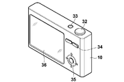
- FIG. 25A and 25B illustrate a mirrorless single-lens camera as an example of an imaging apparatus according to the present embodiment.
- FIG. 25A shows the appearance of the camera as seen from the front side
- FIG. 25B shows the appearance of the camera as seen from the back side.
- This camera includes a camera body 10, and a release button 32 and a power button 33 are provided on the upper surface side of the camera body 10.
- a display unit 36 and operation units 34 and 35 are provided on the back side of the camera body 10.
- the display unit 36 is for displaying a captured image.
- An imaging aperture through which light from an imaging target is incident is provided at the center of the front side of the camera body 10, and a mount 37 is provided at a position corresponding to the imaging aperture, and the interchangeable lens 20 is attached to the camera body 10 by the mount 37. It comes to be installed.
- the interchangeable lens 20 is a lens member housed in a lens barrel.
- an image sensor such as a CCD that outputs an image signal corresponding to the subject image formed by the interchangeable lens 20, and a signal processing circuit that processes the image signal output from the image sensor and generates an image , And a recording medium or the like for recording the generated image.
- a recording medium or the like for recording the generated image.
- a high-resolution imaging signal can be obtained.
- a high-resolution image can be generated based on the imaging signal.
- the medium telephoto lens of the present embodiment only the first lens group G1 is moved in the direction of the optical axis Z during focusing. Therefore, like the medium telephoto lens described in Patent Documents 1 and 2, Since it is not necessary to employ a floating mechanism that moves both the first lens group and the second lens group, the mechanism for moving the lens during focusing can be simplified. Cost reduction is possible.
- the axial chromatic aberration can be favorably corrected. Can achieve good resolution performance with little change.
- the second lens group G2 includes a negative 2-1 lens L21 having a concave surface facing the image side, a positive 2-2 lens L22 having a convex surface facing the object side, and an image side. Since it consists of a positive second-3 lens L23 with a convex surface, it is possible to reduce the field curvature change during focusing, which results in good resolution performance with little change from infinity to short distances. Can be achieved.
- the 1-7th lens L17 is an aspherical lens having an aspherical surface on at least one surface, it is possible to reduce the field curvature particularly in the sagittal direction.
- conditional expression (1) performance fluctuations during downsizing and focusing can be suppressed. If the lower limit of conditional expression (1) is not reached, performance fluctuations during focusing can be suppressed, but the amount of extension of the first lens group G1 during focusing increases, making it difficult to reduce the size. If the upper limit of conditional expression (1) is exceeded, the amount of extension of the first lens group G1 during focusing is reduced, which is advantageous for downsizing, but the performance fluctuation during focusing increases, and there is little change from infinity to short distance. Good resolution performance cannot be achieved.
- conditional expression (1-1) is satisfied. Further, it is more preferable that the following conditional expression (1-2) is satisfied, and it is more preferable that the following conditional expression (1-3) is satisfied.
- conditional expression (2) If the lower limit of conditional expression (2) is not reached, the angle of emission from the lens to the image plane can be reduced, but the overall length of the lens becomes longer and it becomes difficult to achieve miniaturization. If the upper limit of conditional expression (2) is exceeded, the total length of the lens is shortened, which is advantageous for downsizing, but the angle of emission from the lens to the image plane increases and the influence on shading increases.
- the overall length of the lens is shortened, which is advantageous for downsizing, but the exit angle from the lens to the image plane is increased, and the influence on shading increases. If the upper limit of condition (3) is exceeded, the exit angle from the lens to the image plane can be reduced, but the overall length of the lens becomes longer, and it becomes difficult to achieve miniaturization.
- conditional expressions (2-1) and (3-1) are satisfied.
- conditional expression (4) it is possible to simultaneously reduce axial chromatic aberration and lateral chromatic aberration. If the lower limit of conditional expression (4) is not reached, lateral chromatic aberration during close-up shooting can be reduced, but axial chromatic aberration and lateral chromatic aberration during infinity shooting increase. If the upper limit of conditional expression (4) is exceeded, axial chromatic aberration and lateral chromatic aberration at infinity can be reduced, but lateral chromatic aberration at short distance shooting increases.
- conditional expression (5) axial chromatic aberration and lateral chromatic aberration can be simultaneously reduced. If the upper limit of conditional expression (5) is exceeded, longitudinal chromatic aberration and lateral chromatic aberration during close-up photography can be reduced, but lateral chromatic aberration during infinity photography increases. If the lower limit of conditional expression (5) is not reached, lateral chromatic aberration at infinity photography can be reduced, but axial chromatic aberration and lateral chromatic aberration at short distance photography increase.
- conditional expression (5-1) is satisfied.
- Tables 1 to 3 show specific lens data corresponding to the configuration of the medium telephoto lens shown in FIGS. 1 (A), (B), and (C). Table 1 shows the basic lens data, and Tables 2 and 3 show other data.
- Si the surface number in the lens data shown in Table 1
- the surface of the component closest to the object side is the first, and is increased sequentially toward the image side.
- the value (mm) of the radius of curvature of the i-th surface from the object side is shown in correspondence with the symbol Ri attached in FIG.
- the column of the surface interval Di indicates the interval (mm) on the optical axis between the i-th surface Si and the i + 1-th surface Si + 1 from the object side.
- the column of Ndi indicates the value of the refractive index for the d line (587.6 nm) between the i-th surface Si and the i + 1-th surface Si + 1 from the object side.
- the column of ⁇ dj shows the Abbe number value for the d-line of the j-th optical element from the object side.
- Table 1 also shows values of paraxial focal length f (mm), F number (FNO.), And angle of view (2 ⁇ ) of the entire system in an infinitely focused state as various data.
- the distance between the first lens group G1 and the second lens group G2 changes with a change in photographing magnification, and thus the surface distance D13 between the first lens group G1 and the second lens group G2.
- the value of is variable.
- Table 2 shows the values at the infinite focus state, the shooting magnification of -0.2x, and the shooting magnification of -0.5x as the data when the shooting magnification of the surface distance D13 changes. Show.
- both surfaces R12 and R13 of the first to seventh lenses L17 constituting the first lens group G1 are aspheric.
- the basic lens data in Table 1 shows the numerical value of the radius of curvature near the optical axis as the radius of curvature of these aspheric surfaces.
- Table 3 shows aspherical data in the medium telephoto lens according to Example 1.
- E indicates that the subsequent numerical value is a “power exponent” with a base of 10
- the numerical value represented by an exponential function with the base of 10 is Indicates that the value before “E” is multiplied.
- “1.0E-02” indicates “1.0 ⁇ 10 ⁇ 2 ”.
- Z is the length (mm) of a perpendicular line drawn from a point on the aspheric surface at a height h from the optical axis to the tangential plane (plane perpendicular to the optical axis) of the apex of the aspheric surface.
- Z Depth of aspheric surface (mm)
- Y Distance from the optical axis to the lens surface (height) (mm)
- K eccentricity
- the aspherical surface of the medium telephoto lens according to Example 1 is expressed by effectively using the orders from A3 to A10 for the aspherical coefficient An based on the above-described aspherical expression (A). ing.
- both surfaces R12 and R13 of the first to seventh lens L17 are aspherical.
- the middle telephoto lenses in Numerical Examples 5 and 6 do not use an aspherical lens, the aspherical data are omitted in the middle telephoto lenses of Numerical Examples 5 and 6.
- the second lens group G2 includes, in order from the object side, a second lens L21 including a negative lens having a concave surface facing the image side, and a convex surface facing the object side.
- the surface number Si is up to 19 because it is composed of the 2-2 lens L22 that is a positive lens directed to it.
- Table 17 shows a summary of the values for the above-described conditional expressions for each example. As can be seen from Table 17, for conditional expressions (1) to (5), the values of the respective examples are within the numerical range.
- [Aberration performance] 7A to 7D respectively show spherical aberration, astigmatism, distortion (distortion aberration), and lateral chromatic aberration in the infinitely focused state in the medium telephoto lens according to Numerical Example 1.
- FIG. FIGS. 8A to 8D show similar aberrations in the in-focus state with an imaging magnification of ⁇ 0.2
- FIGS. 9A to 9D show in-focus with an imaging magnification of ⁇ 0.5.
- Each similar aberration in the state is shown.
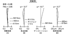
- Each aberration diagram shows an aberration with the d-line (587.6 nm) as a reference wavelength.
- the spherical aberration diagram and the lateral chromatic aberration diagram also show aberrations at a wavelength of 460 nm and a wavelength of 615 nm.
- the solid line indicates the sagittal direction and the broken line indicates the tangential direction.
- FNO. Indicates an F value, and ⁇ indicates a half angle of view.
- FIGS. 10A to 10D the various aberrations of the medium telephoto lens according to Numerical Example 2 are shown in FIGS. 10A to 10D (infinity), FIGS. 11A to 11D (imaging magnification of ⁇ 0.2 times), and 12A to 12D (imaging magnification-0.5 times) are shown.
- FIGS. 13 to 24 (A) to (D) various aberrations of the medium telephoto lens according to Numerical Examples 3 to 6 are shown in FIGS. 13 to 24 (A) to (D).
- this invention is not limited to the said embodiment and each Example, Various deformation
- the values of the radius of curvature, the surface interval, and the refractive index of each lens component are not limited to the values shown in the above numerical examples, and may take other values.
Landscapes
- Physics & Mathematics (AREA)
- General Physics & Mathematics (AREA)
- Optics & Photonics (AREA)
- Lenses (AREA)
Abstract
L'invention concerne un téléobjectif moyen et un dispositif imageur qui présentent une faible aberration chromatique, une taille réduite, des performances améliorées et des coûts limités, dans lesquels un premier groupe de lentilles (G1) et un deuxième groupe de lentilles (G2) à puissance de réfraction positive sont agencés depuis le côté objet, et seul le premier groupe de lentilles (G1) se déplace en direction de l'axe optique lors de la mise au point. Le premier groupe de lentilles (G1) est formé d'une lentille positive 1-1 (L11), d'une lentille positive 1-2 (L12), d'une lentille positive 1-3 (L13), d'une lentille négative 1-4 (L14), d'une ouverture, d'une lentille négative 1-5 (L15), d'une lentille positive 1-6 (L16), et d'une lentille positive 1-7 (L17). La lentille 1-3 et la lentille 1-4 sont regroupées ensemble, et la lentille 1-5 et la lentille 1-6 sont regroupées ensemble. Le deuxième groupe de lentilles (G2) comprend une lentille négative 2-1 (L21) et une lentille positive 2-2 (L22).
Priority Applications (3)
| Application Number | Priority Date | Filing Date | Title |
|---|---|---|---|
| CN201280055704.8A CN103930814B (zh) | 2011-11-14 | 2012-11-12 | 中距远摄镜头和摄像装置 |
| JP2013544121A JP5629389B2 (ja) | 2011-11-14 | 2012-11-12 | 中望遠レンズおよび撮像装置 |
| US14/274,005 US8917456B2 (en) | 2011-11-14 | 2014-05-09 | Medium telephoto lens and imaging device |
Applications Claiming Priority (2)
| Application Number | Priority Date | Filing Date | Title |
|---|---|---|---|
| JP2011248180 | 2011-11-14 | ||
| JP2011-248180 | 2011-11-14 |
Related Child Applications (1)
| Application Number | Title | Priority Date | Filing Date |
|---|---|---|---|
| US14/274,005 Continuation US8917456B2 (en) | 2011-11-14 | 2014-05-09 | Medium telephoto lens and imaging device |
Publications (1)
| Publication Number | Publication Date |
|---|---|
| WO2013073155A1 true WO2013073155A1 (fr) | 2013-05-23 |
Family
ID=48429251
Family Applications (1)
| Application Number | Title | Priority Date | Filing Date |
|---|---|---|---|
| PCT/JP2012/007239 Ceased WO2013073155A1 (fr) | 2011-11-14 | 2012-11-12 | Téléobjectif moyen et dispositif imageur |
Country Status (4)
| Country | Link |
|---|---|
| US (1) | US8917456B2 (fr) |
| JP (1) | JP5629389B2 (fr) |
| CN (1) | CN103930814B (fr) |
| WO (1) | WO2013073155A1 (fr) |
Cited By (4)
| Publication number | Priority date | Publication date | Assignee | Title |
|---|---|---|---|---|
| JP2021009283A (ja) * | 2019-06-29 | 2021-01-28 | エーエーシー オプティックス ソリューションズ ピーティーイー リミテッド | 撮像光学レンズ |
| JP2022113092A (ja) * | 2021-01-22 | 2022-08-03 | 北京小米移動軟件有限公司 | 撮像レンズ、撮像装置及び電子機器 |
| JP2023130072A (ja) * | 2022-03-07 | 2023-09-20 | 株式会社コシナ | マクロレンズ |
| JPWO2024203170A1 (fr) * | 2023-03-27 | 2024-10-03 |
Families Citing this family (4)
| Publication number | Priority date | Publication date | Assignee | Title |
|---|---|---|---|---|
| JP2016095441A (ja) * | 2014-11-17 | 2016-05-26 | 富士フイルム株式会社 | ズームレンズおよび光学装置 |
| JP7086640B2 (ja) * | 2018-02-28 | 2022-06-20 | キヤノン株式会社 | 光学系およびそれを有する撮像装置 |
| KR102893639B1 (ko) * | 2020-11-30 | 2025-12-01 | 삼성전자주식회사 | 렌즈 어셈블리를 포함하는 전자 장치 |
| CN113204106B (zh) * | 2021-05-19 | 2022-05-06 | 郑州阿特尔光电技术有限公司 | 一种宽幅高分辨率可见光镜头光学系统 |
Citations (4)
| Publication number | Priority date | Publication date | Assignee | Title |
|---|---|---|---|---|
| JPH0281015A (ja) * | 1988-09-19 | 1990-03-22 | Nikon Corp | 近距離撮影可能な望遠レンズ |
| JP2002139668A (ja) * | 2000-08-23 | 2002-05-17 | Asahi Optical Co Ltd | 中望遠レンズ |
| JP2004212692A (ja) * | 2003-01-06 | 2004-07-29 | Tamron Co Ltd | マクロレンズ |
| JP2011253050A (ja) * | 2010-06-02 | 2011-12-15 | Canon Inc | 光学系及びそれを有する光学機器 |
Family Cites Families (14)
| Publication number | Priority date | Publication date | Assignee | Title |
|---|---|---|---|---|
| JPS58209707A (ja) * | 1982-05-31 | 1983-12-06 | Asahi Optical Co Ltd | 超コンパクト望遠レンズ |
| US4852984A (en) * | 1987-02-25 | 1989-08-01 | Canon Kabushiki Kaisha | Telephoto lens of large aperture ratio |
| JPH07199066A (ja) * | 1993-12-28 | 1995-08-04 | Nikon Corp | 大口径中望遠レンズ |
| JP3394592B2 (ja) * | 1994-05-02 | 2003-04-07 | オリンパス光学工業株式会社 | 望遠レンズ |
| US5717527A (en) * | 1995-11-28 | 1998-02-10 | Nikon Corporation | Zoom lens |
| KR100256205B1 (ko) * | 1995-12-11 | 2000-05-15 | 유무성 | 소형 줌렌즈 |
| US6317275B1 (en) * | 1999-04-02 | 2001-11-13 | Asahi Kogaku Kogyo Kabushiki Kaisha | Internal focusing telephoto lens |
| US6549343B2 (en) | 2000-08-23 | 2003-04-15 | Pentax Corporation | Intermediate telephoto lens system |
| CN100410715C (zh) * | 2005-03-31 | 2008-08-13 | 财团法人工业技术研究院 | 变焦镜头 |
| US7453651B2 (en) * | 2006-02-28 | 2008-11-18 | Casio Computer Co., Ltd. | Zoom lens and camera with zoom lens |
| JP4890090B2 (ja) * | 2006-05-10 | 2012-03-07 | Hoya株式会社 | ズームレンズ系 |
| JP4561707B2 (ja) * | 2006-05-24 | 2010-10-13 | カシオ計算機株式会社 | ズームレンズ及びプロジェクタ装置 |
| CN100589008C (zh) * | 2007-03-06 | 2010-02-10 | 扬明光学股份有限公司 | 变焦镜头 |
| KR20090087422A (ko) * | 2008-02-12 | 2009-08-17 | 가부시키가이샤 니콘 | 촬영 렌즈, 촬영 렌즈를 구비한 광학 기기 및 촬영 렌즈의 제조 방법 |
-
2012
- 2012-11-12 WO PCT/JP2012/007239 patent/WO2013073155A1/fr not_active Ceased
- 2012-11-12 JP JP2013544121A patent/JP5629389B2/ja active Active
- 2012-11-12 CN CN201280055704.8A patent/CN103930814B/zh active Active
-
2014
- 2014-05-09 US US14/274,005 patent/US8917456B2/en active Active
Patent Citations (4)
| Publication number | Priority date | Publication date | Assignee | Title |
|---|---|---|---|---|
| JPH0281015A (ja) * | 1988-09-19 | 1990-03-22 | Nikon Corp | 近距離撮影可能な望遠レンズ |
| JP2002139668A (ja) * | 2000-08-23 | 2002-05-17 | Asahi Optical Co Ltd | 中望遠レンズ |
| JP2004212692A (ja) * | 2003-01-06 | 2004-07-29 | Tamron Co Ltd | マクロレンズ |
| JP2011253050A (ja) * | 2010-06-02 | 2011-12-15 | Canon Inc | 光学系及びそれを有する光学機器 |
Cited By (7)
| Publication number | Priority date | Publication date | Assignee | Title |
|---|---|---|---|---|
| JP2021009283A (ja) * | 2019-06-29 | 2021-01-28 | エーエーシー オプティックス ソリューションズ ピーティーイー リミテッド | 撮像光学レンズ |
| JP2022113092A (ja) * | 2021-01-22 | 2022-08-03 | 北京小米移動軟件有限公司 | 撮像レンズ、撮像装置及び電子機器 |
| JP7285285B2 (ja) | 2021-01-22 | 2023-06-01 | 北京小米移動軟件有限公司 | 撮像レンズ、撮像装置及び電子機器 |
| US12189099B2 (en) | 2021-01-22 | 2025-01-07 | Beijing Xiaomi Mobile Software Co., Ltd. | Photographing lens system, photographing device and electronic apparatus |
| JP2023130072A (ja) * | 2022-03-07 | 2023-09-20 | 株式会社コシナ | マクロレンズ |
| JP7836073B2 (ja) | 2022-03-07 | 2026-03-26 | 株式会社コシナ | マクロレンズ |
| JPWO2024203170A1 (fr) * | 2023-03-27 | 2024-10-03 |
Also Published As
| Publication number | Publication date |
|---|---|
| JPWO2013073155A1 (ja) | 2015-04-02 |
| US20140247506A1 (en) | 2014-09-04 |
| CN103930814A (zh) | 2014-07-16 |
| US8917456B2 (en) | 2014-12-23 |
| CN103930814B (zh) | 2016-06-29 |
| JP5629389B2 (ja) | 2014-11-19 |
Similar Documents
| Publication | Publication Date | Title |
|---|---|---|
| JP5624377B2 (ja) | ズームレンズおよび撮像装置 | |
| JP5402015B2 (ja) | リアフォーカス光学系、撮像装置、リアフォーカス光学系の合焦方法 | |
| JP5373515B2 (ja) | ズームレンズおよび撮像装置 | |
| JP6388842B2 (ja) | 撮像レンズおよび撮像装置 | |
| JP5890065B2 (ja) | ズームレンズおよび撮像装置 | |
| JP6234784B2 (ja) | ズームレンズおよび撮像装置 | |
| JP2015094883A (ja) | ズームレンズおよび撮像装置 | |
| WO2013099214A1 (fr) | Lentille d'imagerie et dispositif d'imagerie | |
| JP4280538B2 (ja) | ズームレンズ | |
| JP5629389B2 (ja) | 中望遠レンズおよび撮像装置 | |
| JP5860565B2 (ja) | ズームレンズおよび撮像装置 | |
| JP2017146478A (ja) | 撮像レンズおよび撮像装置 | |
| JP5042913B2 (ja) | ズームレンズおよび撮像装置 | |
| JP5373514B2 (ja) | ズームレンズおよび撮像装置 | |
| CN106990514B (zh) | 变焦透镜和包括变焦透镜的图像拾取装置 | |
| JPWO2013031185A1 (ja) | ズームレンズおよび撮像装置 | |
| WO2014141349A1 (fr) | Objectif grand angle et dispositif d'imagerie | |
| JP5583864B2 (ja) | ズームレンズおよび撮像装置 | |
| JPWO2013031183A1 (ja) | ズームレンズおよび撮像装置 | |
| JPWO2013031110A1 (ja) | ズームレンズおよび撮像装置 | |
| JP5796919B2 (ja) | レトロフォーカス型広角レンズおよび撮像装置 | |
| JP5767710B2 (ja) | ズームレンズおよび撮像装置 | |
| JP5767334B2 (ja) | ズームレンズおよび撮像装置 | |
| JP5767333B2 (ja) | ズームレンズおよび撮像装置 | |
| JP5224468B2 (ja) | ズームレンズおよび撮像装置 |
Legal Events
| Date | Code | Title | Description |
|---|---|---|---|
| 121 | Ep: the epo has been informed by wipo that ep was designated in this application |
Ref document number: 12849734 Country of ref document: EP Kind code of ref document: A1 |
|
| ENP | Entry into the national phase |
Ref document number: 2013544121 Country of ref document: JP Kind code of ref document: A |
|
| NENP | Non-entry into the national phase |
Ref country code: DE |
|
| 122 | Ep: pct application non-entry in european phase |
Ref document number: 12849734 Country of ref document: EP Kind code of ref document: A1 |