WO2013076827A1 - 車両用自動変速機 - Google Patents
車両用自動変速機 Download PDFInfo
- Publication number
- WO2013076827A1 WO2013076827A1 PCT/JP2011/076956 JP2011076956W WO2013076827A1 WO 2013076827 A1 WO2013076827 A1 WO 2013076827A1 JP 2011076956 W JP2011076956 W JP 2011076956W WO 2013076827 A1 WO2013076827 A1 WO 2013076827A1
- Authority
- WO
- WIPO (PCT)
- Prior art keywords
- automatic transmission
- engagement
- hydraulic pressure
- brake
- engaged
- Prior art date
- Legal status (The legal status is an assumption and is not a legal conclusion. Google has not performed a legal analysis and makes no representation as to the accuracy of the status listed.)
- Ceased
Links
Images




Classifications
-
- F—MECHANICAL ENGINEERING; LIGHTING; HEATING; WEAPONS; BLASTING
- F15—FLUID-PRESSURE ACTUATORS; HYDRAULICS OR PNEUMATICS IN GENERAL
- F15B—SYSTEMS ACTING BY MEANS OF FLUIDS IN GENERAL; FLUID-PRESSURE ACTUATORS, e.g. SERVOMOTORS; DETAILS OF FLUID-PRESSURE SYSTEMS, NOT OTHERWISE PROVIDED FOR
- F15B15/00—Fluid-actuated devices for displacing a member from one position to another; Gearing associated therewith
- F15B15/02—Mechanical layout characterised by the means for converting the movement of the fluid-actuated element into movement of the finally-operated member
-
- F—MECHANICAL ENGINEERING; LIGHTING; HEATING; WEAPONS; BLASTING
- F16—ENGINEERING ELEMENTS AND UNITS; GENERAL MEASURES FOR PRODUCING AND MAINTAINING EFFECTIVE FUNCTIONING OF MACHINES OR INSTALLATIONS; THERMAL INSULATION IN GENERAL
- F16H—GEARING
- F16H3/00—Toothed gearings for conveying rotary motion with variable gear ratio or for reversing rotary motion
- F16H3/44—Toothed gearings for conveying rotary motion with variable gear ratio or for reversing rotary motion using gears having orbital motion
- F16H3/62—Gearings having three or more central gears
- F16H3/66—Gearings having three or more central gears composed of a number of gear trains without drive passing from one train to another
- F16H3/663—Gearings having three or more central gears composed of a number of gear trains without drive passing from one train to another with conveying rotary motion between axially spaced orbital gears, e.g. a stepped orbital gear or Ravigneaux
-
- F—MECHANICAL ENGINEERING; LIGHTING; HEATING; WEAPONS; BLASTING
- F16—ENGINEERING ELEMENTS AND UNITS; GENERAL MEASURES FOR PRODUCING AND MAINTAINING EFFECTIVE FUNCTIONING OF MACHINES OR INSTALLATIONS; THERMAL INSULATION IN GENERAL
- F16D—COUPLINGS FOR TRANSMITTING ROTATION; CLUTCHES; BRAKES
- F16D25/00—Fluid-actuated clutches
- F16D25/06—Fluid-actuated clutches in which the fluid actuates a piston incorporated in, i.e. rotating with the clutch
- F16D25/061—Fluid-actuated clutches in which the fluid actuates a piston incorporated in, i.e. rotating with the clutch the clutch having interengaging clutch members
-
- F—MECHANICAL ENGINEERING; LIGHTING; HEATING; WEAPONS; BLASTING
- F16—ENGINEERING ELEMENTS AND UNITS; GENERAL MEASURES FOR PRODUCING AND MAINTAINING EFFECTIVE FUNCTIONING OF MACHINES OR INSTALLATIONS; THERMAL INSULATION IN GENERAL
- F16H—GEARING
- F16H57/00—General details of gearing
- F16H57/08—General details of gearing of gearings with members having orbital motion
- F16H57/10—Braking arrangements
-
- F—MECHANICAL ENGINEERING; LIGHTING; HEATING; WEAPONS; BLASTING
- F16—ENGINEERING ELEMENTS AND UNITS; GENERAL MEASURES FOR PRODUCING AND MAINTAINING EFFECTIVE FUNCTIONING OF MACHINES OR INSTALLATIONS; THERMAL INSULATION IN GENERAL
- F16H—GEARING
- F16H63/00—Control outputs from the control unit to change-speed- or reversing-gearings for conveying rotary motion or to other devices than the final output mechanism
- F16H63/02—Final output mechanisms therefor; Actuating means for the final output mechanisms
- F16H63/30—Constructional features of the final output mechanisms
- F16H63/3023—Constructional features of the final output mechanisms the final output mechanisms comprising elements moved by fluid pressure
-
- F—MECHANICAL ENGINEERING; LIGHTING; HEATING; WEAPONS; BLASTING
- F16—ENGINEERING ELEMENTS AND UNITS; GENERAL MEASURES FOR PRODUCING AND MAINTAINING EFFECTIVE FUNCTIONING OF MACHINES OR INSTALLATIONS; THERMAL INSULATION IN GENERAL
- F16H—GEARING
- F16H63/00—Control outputs from the control unit to change-speed- or reversing-gearings for conveying rotary motion or to other devices than the final output mechanism
- F16H63/02—Final output mechanisms therefor; Actuating means for the final output mechanisms
- F16H63/30—Constructional features of the final output mechanisms
- F16H2063/3093—Final output elements, i.e. the final elements to establish gear ratio, e.g. coupling sleeves or other means establishing coupling to shaft
-
- F—MECHANICAL ENGINEERING; LIGHTING; HEATING; WEAPONS; BLASTING
- F16—ENGINEERING ELEMENTS AND UNITS; GENERAL MEASURES FOR PRODUCING AND MAINTAINING EFFECTIVE FUNCTIONING OF MACHINES OR INSTALLATIONS; THERMAL INSULATION IN GENERAL
- F16H—GEARING
- F16H2200/00—Transmissions for multiple ratios
- F16H2200/003—Transmissions for multiple ratios characterised by the number of forward speeds
- F16H2200/0052—Transmissions for multiple ratios characterised by the number of forward speeds the gear ratios comprising six forward speeds
-
- F—MECHANICAL ENGINEERING; LIGHTING; HEATING; WEAPONS; BLASTING
- F16—ENGINEERING ELEMENTS AND UNITS; GENERAL MEASURES FOR PRODUCING AND MAINTAINING EFFECTIVE FUNCTIONING OF MACHINES OR INSTALLATIONS; THERMAL INSULATION IN GENERAL
- F16H—GEARING
- F16H2200/00—Transmissions for multiple ratios
- F16H2200/20—Transmissions using gears with orbital motion
- F16H2200/2002—Transmissions using gears with orbital motion characterised by the number of sets of orbital gears
- F16H2200/2007—Transmissions using gears with orbital motion characterised by the number of sets of orbital gears with two sets of orbital gears
-
- F—MECHANICAL ENGINEERING; LIGHTING; HEATING; WEAPONS; BLASTING
- F16—ENGINEERING ELEMENTS AND UNITS; GENERAL MEASURES FOR PRODUCING AND MAINTAINING EFFECTIVE FUNCTIONING OF MACHINES OR INSTALLATIONS; THERMAL INSULATION IN GENERAL
- F16H—GEARING
- F16H2200/00—Transmissions for multiple ratios
- F16H2200/20—Transmissions using gears with orbital motion
- F16H2200/202—Transmissions using gears with orbital motion characterised by the type of Ravigneaux set
-
- F—MECHANICAL ENGINEERING; LIGHTING; HEATING; WEAPONS; BLASTING
- F16—ENGINEERING ELEMENTS AND UNITS; GENERAL MEASURES FOR PRODUCING AND MAINTAINING EFFECTIVE FUNCTIONING OF MACHINES OR INSTALLATIONS; THERMAL INSULATION IN GENERAL
- F16H—GEARING
- F16H2200/00—Transmissions for multiple ratios
- F16H2200/20—Transmissions using gears with orbital motion
- F16H2200/202—Transmissions using gears with orbital motion characterised by the type of Ravigneaux set
- F16H2200/2023—Transmissions using gears with orbital motion characterised by the type of Ravigneaux set using a Ravigneaux set with 4 connections
-
- F—MECHANICAL ENGINEERING; LIGHTING; HEATING; WEAPONS; BLASTING
- F16—ENGINEERING ELEMENTS AND UNITS; GENERAL MEASURES FOR PRODUCING AND MAINTAINING EFFECTIVE FUNCTIONING OF MACHINES OR INSTALLATIONS; THERMAL INSULATION IN GENERAL
- F16H—GEARING
- F16H2200/00—Transmissions for multiple ratios
- F16H2200/20—Transmissions using gears with orbital motion
- F16H2200/203—Transmissions using gears with orbital motion characterised by the engaging friction means not of the freewheel type, e.g. friction clutches or brakes
- F16H2200/2043—Transmissions using gears with orbital motion characterised by the engaging friction means not of the freewheel type, e.g. friction clutches or brakes with five engaging means
-
- F—MECHANICAL ENGINEERING; LIGHTING; HEATING; WEAPONS; BLASTING
- F16—ENGINEERING ELEMENTS AND UNITS; GENERAL MEASURES FOR PRODUCING AND MAINTAINING EFFECTIVE FUNCTIONING OF MACHINES OR INSTALLATIONS; THERMAL INSULATION IN GENERAL
- F16H—GEARING
- F16H2200/00—Transmissions for multiple ratios
- F16H2200/20—Transmissions using gears with orbital motion
- F16H2200/203—Transmissions using gears with orbital motion characterised by the engaging friction means not of the freewheel type, e.g. friction clutches or brakes
- F16H2200/2064—Transmissions using gears with orbital motion characterised by the engaging friction means not of the freewheel type, e.g. friction clutches or brakes using at least one positive clutch, e.g. dog clutch
-
- F—MECHANICAL ENGINEERING; LIGHTING; HEATING; WEAPONS; BLASTING
- F16—ENGINEERING ELEMENTS AND UNITS; GENERAL MEASURES FOR PRODUCING AND MAINTAINING EFFECTIVE FUNCTIONING OF MACHINES OR INSTALLATIONS; THERMAL INSULATION IN GENERAL
- F16H—GEARING
- F16H2200/00—Transmissions for multiple ratios
- F16H2200/20—Transmissions using gears with orbital motion
- F16H2200/2079—Transmissions using gears with orbital motion using freewheel type mechanisms, e.g. freewheel clutches
- F16H2200/2082—Transmissions using gears with orbital motion using freewheel type mechanisms, e.g. freewheel clutches one freewheel mechanisms
Definitions
- the present invention relates to an automatic transmission for a vehicle, and more particularly to an improvement for simplifying the configuration of the apparatus.
- a plurality of engagement elements whose engagement states are switched by hydraulic pressure are provided, and a plurality of shift speeds are selectively selected based on a combination of engagement and release of the plurality of engagement elements according to the hydraulic pressure supplied from a hydraulic circuit.
- a multi-stage automatic transmission for a vehicle to be established is known.
- a clutch or a brake having a wet friction material has been widely used as the engagement element.
- loss due to dragging is a problem. It has been.
- an automatic transmission using a meshing engagement element that is, a so-called dog clutch (meshing clutch) has been proposed as an alternative to the wet friction material.
- a meshing engagement element that is, a so-called dog clutch (meshing clutch) has been proposed as an alternative to the wet friction material.
- a so-called dog clutch meshing clutch
- the conventional technology can suppress the occurrence of drag by replacing the wet friction material with a dog clutch, it cannot solve the problem of using a lot of hydraulic pressure at the time of start, stop, and eco-run, and it is a structural limitation.
- the inventors of the present invention have continually studied to improve the performance of the automatic transmission for a vehicle, but as a result of the research, the present invention has been achieved.
- the present invention has been made against the background of the above circumstances, and an object of the present invention is to provide an automatic transmission for a vehicle having a simple device configuration.
- the gist of the first aspect of the present invention includes a plurality of engagement elements whose engagement states are switched by hydraulic pressure, and the plurality of engagement elements according to the hydraulic pressure supplied from a hydraulic circuit.
- a multi-stage automatic transmission for a vehicle that selectively establishes a plurality of shift speeds based on a combination of engagement and release of a combination element, wherein at least one of the plurality of engagement elements is the hydraulic circuit It is a normally closed type engaging element that is engaged when the hydraulic pressure from is not supplied.
- the plurality of engagement elements whose engagement states are switched by the hydraulic pressure are provided, and the engagement elements are engaged or released according to the hydraulic pressure supplied from the hydraulic circuit.
- a multi-stage vehicular automatic transmission that selectively establishes a plurality of shift speeds based on a combination, at least one of the plurality of engagement elements is engaged when hydraulic pressure from the hydraulic circuit is not supplied Since this is a normally closed engagement element, the restriction on the configuration of the hydraulic circuit is reduced, and the oil pump can be downsized. That is, it is possible to provide an automatic transmission for a vehicle that has a simple device configuration.
- the gist of the second invention subordinate to the first invention is that the normally closed engagement element is a meshing engagement element. If it does in this way, in addition to simplification of a structure, generation
- the gist of the third invention subordinate to the first invention or the second invention is that the automatic transmission is engaged when the first gear stage having the largest gear ratio among the forward gear stages is established.
- the plurality of engaging elements at least one is the normally closed engaging element.
- the subject matter of the fourth invention according to the first invention or the second invention is that, in the automatic transmission, at least one of a plurality of engaging elements that are engaged when a reverse gear is established.
- One is the normally closed engagement element.
- the automatic transmission in the automatic transmission, at least one of a plurality of engagement elements that are engaged when the first shift speed is established. It is a normally open type engaging element that is released when the hydraulic pressure from the hydraulic circuit is not supplied. In this way, an automatic transmission having a simple configuration and a practical aspect can be provided.
- the subject matter of the sixth invention which is dependent on the fourth invention, is that, in the automatic transmission, at least one of the plurality of engaging elements engaged when the reverse gear is established is the hydraulic pressure. It is a normally open type engaging element that is released when hydraulic pressure from the circuit is not supplied. In this way, an automatic transmission having a simple configuration and a practical aspect can be provided.
- the gist of the seventh invention subordinate to the sixth invention subordinate to the invention is that the normally closed engagement element includes two mesh brakes and is fixed to the non-rotating member by engagement of the mesh brakes.
- the rotating element is connected directly or indirectly to the output rotating member of the automatic transmission. In this way, an automatic transmission having a simple configuration and a practical aspect can be provided, and the output rotating member is fixed to the non-rotating member in a state where the hydraulic pressure from the hydraulic circuit is not supplied. Therefore, there is an advantage that a configuration for parking lock becomes unnecessary.
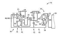
- FIG. 1 is a skeleton diagram illustrating a configuration of a vehicle automatic transmission to which the present invention is preferably applied.
- FIG. 2 is an operation table for explaining operation states of engagement elements when a plurality of shift speeds are selectively established in the automatic transmission of FIG. 1. The presence or absence is also shown in the right column.
- the collinear diagram which can represent on a straight line the relative relationship of the rotational speed of each rotation element from which a connection state differs for every gear stage is shown.
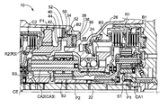
- FIG. 2 is a partial cross-sectional view showing a part of the automatic transmission cut along a plane including a central axis in order to explain a normally closed engagement element provided in the automatic transmission of FIG. 1.
- FIG. 1 is a skeleton diagram illustrating a configuration of a vehicle automatic transmission to which the present invention is preferably applied.
- FIG. 2 is an operation table for explaining operation states of engagement elements when a plurality of shift speeds are selectively established in the automatic transmission of FIG. 1. The presence or absence is also shown in the right column
- FIG. 2 is a schematic cross-sectional view schematically illustrating the operation of a normally closed engagement element provided in the automatic transmission of FIG. 1, showing a state in which the engagement element is engaged.
- FIG. 2 is a schematic cross-sectional view schematically illustrating the operation of a normally closed engagement element provided in the automatic transmission of FIG. 1, showing a state in which the engagement element is released.
- FIG. 8 is an operation table for explaining an operation state of engagement elements when a plurality of shift speeds are selectively established in the automatic transmission of FIG. 7. The presence or absence is also shown in the right column.
- FIG. 8 is a partial cross-sectional view showing a part of the automatic transmission cut along a plane including a central axis in order to describe a normally closed engagement element provided in the automatic transmission of FIG. 7.
- the normally-closed engagement element is a claw portion that is engaged with each other in correspondence with each of a pair of members to be engaged (relative rotation prevention) to release (relative rotation permission).
- a meshing engagement device (dog clutch) that includes a pair of engagement members having a plurality of engagement members, and the engagement state is switched by relatively moving the pair of engagement members according to the hydraulic pressure supplied from the hydraulic circuit. : Dog clutch).
- Dog clutch Preferably, for example, a cylinder, a piston provided so as to be able to reciprocate in the cylinder, and a spring for biasing the piston in the engaging direction of the claw portion are provided, and when the hydraulic pressure is not supplied, the spring is attached. The piston is moved and engaged in the direction in which the claw engages with the force, while the piston is moved in the direction in which the engagement of the claw is released against the urging force of the spring when hydraulic pressure is supplied and released. It is an engagement device.
- the normally closed engagement element is preferably a brake that fixes the rotating member with respect to the non-rotating member by engagement, and more preferably a meshing brake.
- This normally closed engagement element is preferably engaged at the first shift stage and the reverse shift stage having the largest speed ratio among the forward shift stages.
- the automatic transmission engages at least the normally-closed engagement element in the first shift stage and the reverse shift stage having the largest speed ratio among the forward shift stages.
- the normally closed engagement element may be a friction engagement device, and in this aspect, the advantageous effect of the present invention is achieved.
- the automatic transmission includes an input clutch (starting clutch) that connects and disconnects between the input rotating member and the output rotating member, and forward shifting is performed by engagement of the input clutch and the normally closed engagement element.
- the first gear stage having the largest gear ratio among the stages is established.
- the input clutch is preferably a normally open type engagement element that is released when hydraulic pressure from the hydraulic circuit is not supplied, and more preferably a hydraulic friction engagement device such as a multi-plate clutch. .
- FIG. 1 is a skeleton diagram illustrating the configuration of a vehicle automatic transmission 10 to which the present invention is preferably applied.
- an automatic transmission 10 according to the present embodiment is a laterally mounted device that is preferably used for an FF vehicle or the like, and is mainly composed of a single pinion type first planetary gear device 12.
- a first transmission unit 14 and a second transmission unit 20 mainly composed of a double pinion type second planetary gear unit 16 and a single pinion type third planetary gear unit 18 on a coaxial line,
- the rotation of the shaft 22 is changed and output from the output rotating member 24.
- the input shaft 22 corresponds to an input rotating member.
- the input shaft 22 is a turbine shaft of a torque converter 30 that is rotationally driven by an engine 28 that is an internal combustion engine for generating vehicle power.
- the output rotating member 24 corresponds to an output member of the automatic transmission 10, and an output gear, that is, a differential drive gear that meshes with a differential driven gear (large diameter gear) to transmit power to a differential gear device (not shown). Is functioning.
- the output of the engine 28 is transmitted to a pair of drive wheels (front wheels) via the torque converter 30, the automatic transmission 10, the differential gear device, and a pair of axles as drive shafts.
- the automatic transmission 10 is configured substantially symmetrically with respect to the center line, and the lower half of the center line is omitted in FIG. This is the same in the following description.
- the engine 28 is a driving source (main power source) that generates driving force for traveling, and is an internal combustion engine such as a gasoline engine or a diesel engine that generates driving force of a vehicle by combustion of fuel.
- the torque converter 30 includes a pump impeller 30a connected to the crankshaft of the engine 28, a turbine impeller 30b connected to the input shaft 22 of the automatic transmission 10, and the automatic transmission via a one-way clutch. And a stator impeller 30c coupled to a housing (transmission case) 26 of the machine 10, and a fluid transmission device that transmits the power generated by the engine 28 to the automatic transmission 10 via a fluid. is there.
- a lockup clutch 32 which is a direct coupling clutch, is provided between the pump impeller 30a and the turbine impeller 30b, and is brought into an engaged state, a slip state, or a released state by hydraulic control or the like. Yes. When the lockup clutch 32 is completely engaged, the pump impeller 30a and the turbine impeller 30b are integrally rotated.
- the first planetary gear unit 12 is of a single pinion type having a sun gear S1, a plurality of pinion gears P1, a carrier CA1 that supports the pinion gears P1 so as to be capable of rotating and revolving, and a ring gear R1 that meshes with the sun gear S1 via the pinion gears P1. It is a planetary gear device.
- the second planetary gear device 16 and the third planetary gear device 18 are configured in a Ravigneaux type in which a ring gear R2 (R3) and a carrier CA2 (CA3) are integrally formed.
- the second planetary gear device 16 includes a plurality of pinion gears P2 meshed with each other, supports the pinion gears P2 so as to be capable of rotating and revolving by the carrier CA2, and is engaged with the ring gear R2 via the pinion gears P2.
- the third planetary gear unit 18 includes a plurality of pinion gears P3 and supports the pinion gears P3 by the carrier CA3 so as to be capable of rotating and revolving, and a single pinion having a sun gear S3 that meshes with the ring gear R3 via the pinion gears P3.
- Type planetary gear device A sun gear S ⁇ b> 1 of the first planetary gear device 12 is connected to the input shaft 22.
- the carrier CA1 of the first planetary gear device 12 and the sun gear S2 of the second planetary gear device 16 are integrally connected.
- a carrier CA ⁇ b> 2 of the second planetary gear device 16 (a carrier CA ⁇ b> 3 of the third planetary gear device 18) is connected to the output rotation member 24.
- the automatic transmission 10 includes a plurality of engagement elements whose engagement state is switched by hydraulic pressure. That is, a first clutch C1 that selectively engages the input shaft 22 and the sun gear S3 is provided between the input shaft 22 and the sun gear S3 of the third planetary gear unit 18. A second gear for selectively engaging the input shaft 22 and the ring gear R2 (R3) between the input shaft 22 and the ring gear R2 of the second planetary gear device 16 (ring gear R3 of the third planetary gear device 18). A clutch C2 is provided.
- the carrier CA1 (sun gear S2) is selectively selected with respect to the housing 26 between the housing 26, which is a non-rotating member, and the carrier CA1 of the first planetary gear device 12 (sun gear S2 of the second planetary gear device 16).
- a first brake B1 is provided to be engaged with the first brake B1.
- a second ring gear R2 (R3) is selectively engaged with the housing 26 between the housing 26 and the ring gear R2 of the second planetary gear device 16 (ring gear R3 of the third planetary gear device 18).
- a brake B2 is provided.
- a third brake B3 that selectively engages the ring gear R1 with the housing 26 is provided between the housing 26 and the ring gear R1 of the first planetary gear device 12.
- FIG. 2 is an operation table for explaining the operation states of the engagement elements when a plurality of shift stages are selectively established in the automatic transmission 10, and the engagement / release of each engagement element at each shift stage. Is shown in the left column, and whether or not the hydraulic pressure is supplied to the engagement element at each gear stage is also shown in the right column.
- the left column of FIG. 2 shows the shift speeds established by the automatic transmission 10 and the first clutch C1, the second clutch C2, the first brake B1, the second brake B2, and the third brake B3 (hereinafter not particularly distinguished).
- the relationship between the operating state of the clutch C and the brake B) is summarized, and “ ⁇ ” indicates engagement and the blank indicates release.
- the clutch C, the first brake B1, and the third brake B3 provided in the automatic transmission 10 are all hydraulic friction engagement devices controlled to be engaged by a hydraulic actuator such as a multi-plate clutch or a brake. Energized, de-energized and current control of the linear solenoid valve provided in the hydraulic circuit 60 (see FIG. 5 etc.) switches the engaged / released state, and controls the transient hydraulic pressure at the time of engagement / release. It has become.
- the second brake B2 includes a pair of engaging members having claw portions that are engaged with each other, corresponding to the housing 26 that is a non-rotating member and the ring gear R2 (R3) that is a rotating member, This is a meshing engagement device (dog clutch) in which the engagement state is switched by relatively moving the pair of engagement members according to the hydraulic pressure supplied from the hydraulic circuit 60.
- This is a meshing engagement device (dog clutch) in which the engagement state is switched by relatively moving the pair of engagement members according to the hydraulic pressure supplied from the hydraulic circuit 60.
- the operation of the second brake B2 will be described later with reference to FIGS.
- a one-way clutch F1 that allows one-way rotation of the ring gear R2 (R3) relative to the housing 26 and prevents reverse rotation is in parallel with the second brake B2. Is provided.
- the one-way clutch F1 prevents the relative rotation of the ring gear R2 (R3) with respect to the housing 26, the second brake B2 may not be engaged.
- the one-way clutch F1 is not
- the right column of FIG. 2 indicates the presence or absence of hydraulic pressure generation (hydraulic pressure supply from the hydraulic circuit 60) for each engagement element. “O” indicates that the hydraulic pressure is generated, and “X” indicates that no hydraulic pressure is generated. ", Respectively.
- the second brake B2 there is no generation of hydraulic pressure when engaged in correspondence with each gear, and there is generation of hydraulic pressure when released. That is, the second brake B2 is a normally closed engagement element that is engaged when the hydraulic pressure from the hydraulic circuit 60 is not supplied, and is released when the hydraulic pressure is supplied. .
- the clutch C, the first brake B1, and the third brake B3 oil pressure is generated when engaged in correspondence with each gear, and no oil pressure is generated when released. That is, the clutch C, the first brake B1, and the third brake B3 are all released when the hydraulic pressure from the hydraulic circuit 60 is not supplied, and are normally opened when the hydraulic pressure is supplied. (Normally open) engagement element.
- the first speed change according to the combination of the connected states of the rotating elements (sun gears S1 to S3, carriers CA1 to CA3, ring gears R1 to R3) of the first transmission unit 14 and the second transmission unit 20.
- Six forward shift stages from the stage “1st” to the sixth shift stage “6th” are established, and the reverse shift stage of the reverse shift stage “R” is established.
- the first gear stage “1st” having the maximum gear ratio ⁇ is established by the engagement of the first clutch C1 and the second brake B2.
- the engagement of the first clutch C1 and the first brake B1 establishes the second speed “2nd” in which the speed ratio ⁇ is smaller than the first speed.
- the engagement of the first clutch C1 and the third brake B3 establishes the third speed “3rd” in which the speed ratio ⁇ is smaller than the second speed.
- the engagement of the first clutch C1 and the second clutch C2 establishes the fourth speed “4th” in which the speed ratio ⁇ is smaller than the third speed.
- a fifth shift stage “5th” in which the speed ratio ⁇ is smaller than the fourth shift stage is established.
- the sixth shift stage “6th” having the smallest speed ratio ⁇ is established by engagement of the second clutch C2 and the first brake B1.
- the reverse shift stage “Rev” is established by the engagement of the second brake B2 and the third brake B3.
- Both the clutch C and the brake B are configured to be in a neutral state by being released.
- the second brake B2 since the one-way clutch F1 is provided in parallel with the second brake B2 that establishes the first shift stage “1st”, the second brake B2 is not necessarily the second at the time of start (acceleration). There is no need to engage the brake B2.
- FIG. 3 is a collinear diagram that can represent, on a straight line, the relative relationship between the rotational speeds of the rotating elements having different connection states for each gear position in the automatic transmission 10.
- the collinear chart of FIG. 3 is a two-dimensional coordinate that shows the relative relationship of the gear ratio ⁇ of each planetary gear device 12, 16, 18 in the horizontal axis direction and the relative rotational speed in the vertical axis direction.
- a horizontal line X1 indicates zero rotation speed.
- the upper horizontal line X2 indicates the rotational speed “1.0”, that is, the rotational speed N IN of the input shaft 22.
- the seven vertical lines Y1 to Y7 indicate that, in order from the left, Y1 is the sun gear S1 of the first planetary gear unit 12, Y2 is the carrier CA1, Y3 is the ring gear R1, Y4 is the sun gear S2, Y5 of the second planetary gear unit 16. Is the ring gear R2 (R3), Y6 is the carrier CA2 (CA3), and Y7 is the relative rotational speed of the sun gear S3 of the third planetary gear unit 18.
- the intervals between the vertical lines Y1 to Y7 are determined according to the gear ratios ⁇ 1, ⁇ 2, and ⁇ 3 of the planetary gear devices 12, 16, and 18, respectively.
- the input shaft 22 that is an input rotation member is selectively coupled to the sun gear S3 via the first clutch C1, and It is selectively connected to the ring gear R2 (R3) via the second clutch C2.
- the carrier CA1 and the sun gear S2 that are connected to each other are selectively connected to the housing 26 that is a non-rotating member via the first brake B1.
- the ring gear R2 (R3) is selectively connected to the housing 26 via the second brake B2.
- the ring gear R1 is selectively connected to the housing 26 via the third brake B3.
- the sun gear S1 is coupled to the input shaft 22.
- the carrier CA2 (CA3) is coupled to the output rotating member 24.
- the relative relationship between the rotational speeds of the rotating elements is determined according to the combination of engagement and release of the clutch C and the brake B at the time of establishment of each gear.
- the relationship corresponding to the first shift stage “1st” is indicated by a straight line L1.
- a relationship corresponding to the second shift stage “2nd” is indicated by a straight line L2.
- a relationship corresponding to the third shift stage “3rd” is indicated by a straight line L3.
- the relationship corresponding to the fourth speed gear stage “4th” is indicated by a straight line L4.
- the relationship corresponding to the fifth speed gear stage “5th” is indicated by a straight line L5.
- a relationship corresponding to the sixth speed gear stage “6th” is indicated by a straight line L6.
- the relationship corresponding to the reverse gear stage “R” is indicated by a straight line LR.
- the straight lines L1 to L6 and LR are expressed in order to show the relative relationship of the rotational speeds of the rotating elements related to all the shift speeds that can be established in the automatic transmission 10 in one drawing.
- the planetary gear units 12, 16, and 18 are not necessarily straight lines, but the rotational speed of the rotating elements in the planetary gear units 12, 16, and 18 depends on the engagement state of the clutch C and the brake B. By being expressed equally, the relative rotational speeds of the seven rotational elements of the automatic transmission 10 at each gear stage are fully expressed.
- the straight line L ⁇ b> 1 determined by engaging the first clutch C ⁇ b> 1 and the second brake B ⁇ b> 2 and the carrier CA ⁇ b> 2 (CA ⁇ b> 3) connected to the output rotation member 24.
- the rotation speed of the output rotation member 24 at the first gear stage “1st” is indicated by the intersection with the vertical line Y6 indicating the rotation speed of).
- the rotation speed of the output rotation member 24 at the second speed “2nd” is indicated by the intersection of the straight line L2 determined by engaging the first clutch C1 and the first brake B1 and the vertical line Y6.
- the rotation speed of the output rotation member 24 at the third speed “3rd” is indicated by the intersection of the straight line L3 determined by engaging the first clutch C1 and the third brake B3 and the vertical line Y6.
- the rotational speed of the output rotation member 24 at the fourth speed “4th” is indicated by the intersection of the straight line L4 determined by engaging the first clutch C1 and the second clutch C2 and the vertical line Y6.
- the rotation speed of the output rotation member 24 at the fifth speed “5th” is indicated by the intersection of the straight line L5 determined by engaging the second clutch C2 and the third brake B3 and the vertical line Y6.
- the rotational speed of the output rotating member 24 at the sixth shift stage “6th” is indicated by the intersection of the straight line L6 determined by engaging the second clutch C2 and the first brake B1 and the vertical line Y6.
- the rotational speed of the output rotation member 24 at the reverse shift stage “R” is indicated by the intersection of the straight line LR determined by engaging the second brake B2 and the third brake B3 and the vertical line Y6.
- FIG. 4 is a partial cross-sectional view showing a partial configuration of the automatic transmission 10 cut along a plane including a central axis in order to explain the configuration of the second brake B2 and the like.
- the second brake B ⁇ b> 2 is capable of reciprocating in the direction of the central axis CE of the automatic transmission 10 within the cylinder portion 34 formed in the inner peripheral side of the housing 26.
- a spring 38 that urges the piston 36 in the engaging direction of claws 40 and 44 described later.
- a claw portion 40 is formed at the end of the piston 36 on the ring gear R2 (R3) side.
- An extension portion 42 extending toward the outer peripheral side is formed on the piston 36 side of the ring gear R2 (R3), and the end portion on the outer peripheral side meshes with the claw portion 40 of the piston 36.
- a claw portion 44 is formed.
- a groove portion 46 in the central axis direction is formed on the inner peripheral side of the piston 36, and the center of the piston 36 with respect to the cylinder portion 34 is fitted by being fitted in a groove portion 48 formed in the cylinder portion 34. Relative movement in the direction of the central axis CE is allowed while preventing relative rotation around the axis CE.
- An oil chamber 50 is formed between the cylinder portion 34 (housing 26) and the piston 36, and the oil chamber 50 is oil-tight by an oil seal 52 provided on the piston 36. That is, in the second brake B2, the ring gear R2 (R3) and the piston 36 correspond to a pair of engagement members having claw portions 40 and 44 with which the ring 36 is engaged with each other.
- FIGS. 5 and 6 are schematic cross-sectional views schematically illustrating the operation of the second brake B2.
- FIG. 5 shows a state where the second brake B2 is engaged
- FIG. 6 shows that the second brake B2 is released.
- the oil chamber 50 formed between the cylinder portion 34 and the piston 36 is configured to be supplied with hydraulic pressure from the hydraulic circuit 60 via an oil passage 58. ing.
- hydraulic pressure hydraulic pressure that generates at least the force to push back the spring 38 in the axial direction of the piston 36
- the piston 36 is pushed toward the extending portion 42 side of the ring gear R2 (R3), and the pawl portions 40 and 44 provided on the piston 36 and the extending portion 42 are engaged with each other. That is, the second brake B2 is engaged.
- the piston 36 is configured such that the inner circumferential groove 46 is fitted into the groove 48 of the cylinder 34 so that the piston 36 cannot rotate relative to the housing 26, and the claw portions 40 and 44 mesh with each other. As a result, relative rotation about the axis of the piston 36 and the ring gear R2 (R3) is prevented. Therefore, in the state shown in FIG. 5, relative rotation of the ring gear R2 (R3) with respect to the housing 26 is blocked.
- FIG. 7 is a skeleton diagram illustrating the configuration of another vehicular automatic transmission 70 to which the present invention is preferably applied.
- the automatic transmission 70 of the present embodiment includes the first brake B1 as a hydraulic friction engagement device (friction brake) provided in the automatic transmission 10.
- a first brake B1 which is a meshing engagement element is provided.
- the first brake B1 includes a pair of engaging members having claw portions that are engaged with each other corresponding to the housing 26 that is a non-rotating member and the carrier CA1 (sun gear S2) that is a rotating element.
- a meshing engagement device (dog clutch) in which the engagement state is switched by relatively moving the pair of engagement members according to the hydraulic pressure supplied from the hydraulic circuit 60.
- FIG. 8 is an operation table for explaining the operation states of the engagement elements when a plurality of shift stages are selectively established in the automatic transmission 70, and the engagement / release of each engagement element at each shift stage. Is shown in the left column, and whether or not the hydraulic pressure is supplied to the engagement element at each gear stage is also shown in the right column. As shown in the right column of FIG. 8, in the first brake B1 and the second brake B2, no hydraulic pressure is generated when engaged in correspondence with each gear, and hydraulic pressure is generated when released. There is. That is, the first brake B1 and the second brake B2 are of a normally closed type (normally closed) that is engaged when the hydraulic pressure from the hydraulic circuit 60 is not supplied and is released when the hydraulic pressure is supplied. It is an engagement element.
- a normally closed type normally closed
- both the clutch C and the third brake B3 are normally open type that is released when the hydraulic pressure from the hydraulic circuit 60 is not supplied and is engaged when the hydraulic pressure is supplied. It is an engagement element.
- FIG. 9 is a partial cross-sectional view showing a partial configuration of the automatic transmission 70 cut along a plane including a central axis in order to explain the configuration of the first brake B1 and the like.
- the first brake B1 is capable of reciprocating in the direction of the center axis CE of the automatic transmission 70 in the cylinder portion 72 formed on the inner peripheral side of the housing 26.
- a spring 76 that urges the piston 74 in the engaging direction of claws 78 and 82 to be described later.
- a claw portion 78 is formed at the end of the piston 74 on the carrier CA1 side.
- An extension portion 80 extending toward the outer peripheral side is formed on the piston 74 side of the carrier CA1, and a claw portion 82 that meshes with the claw portion 78 of the piston 74 at the outer peripheral side end portion thereof. Is formed.
- a groove portion 84 in the central axis direction is formed on the inner peripheral side of the piston 74, and the center of the piston 74 with respect to the cylinder portion 72 is engaged with a groove portion 86 formed in the cylinder portion 72. Relative movement in the direction of the central axis CE is allowed while preventing relative rotation around the axis CE.
- An oil chamber 88 is formed between the cylinder portion 72 (housing 26) and the piston 74, and the oil chamber 88 is oil-tight by an oil seal 90 provided on the piston 74. That is, in the first brake B1, the carrier CA1 (the sun gear S2 connected to each other) and the piston 74 correspond to a pair of engaging members having pawl portions 78 and 82 that are engaged with each other.
- the first brake B1 configured as described above is operated in the same manner as the second brake B2 described above with reference to FIGS. That is, in the state where the hydraulic pressure (the hydraulic pressure that generates at least the force to push back the spring 76 in the axial direction of the piston 74) is not supplied from the hydraulic circuit 60 to the oil chamber 88, the piston 74 is moved by the biasing force of the spring 76.
- the claw portions 78 and 82 provided on the piston 74 and the extending portion 80 are engaged with each other by being pushed toward the carrier CA1. That is, the first brake B1 is engaged.
- the piston 74 is configured such that the inner circumferential groove 84 is engaged with the groove 86 of the cylinder 72 so that the piston 74 cannot rotate relative to the housing 26, and the claw portions 78 and 82 mesh with each other. As a result, relative rotation around the axis of the piston 74 and the carrier CA1 (sun gear S2) is prevented, and in this state, relative rotation of the carrier CA1 with respect to the housing 26 is prevented.
- the automatic transmission 70 includes the first brake B1 and the second brake which are normally closed meshing brakes engaged when no hydraulic pressure is supplied from the hydraulic circuit 60 and no hydraulic pressure is generated.
- a brake B2 is provided.
- the first brake B1 and the second brake B2 fix the carrier CA1 (sun gear S2) and the ring gear R2 (R3) to the housing 26 that is a non-rotating member by engagement.
- the carrier CA1 (sun gear S2) and the ring gear R2 (R3), which are rotating elements of the automatic transmission 70, are connected via the second planetary gear device 16 and the third planetary gear device 18 that are both configured as Ravigneaux.
- the output rotating member 24 is mechanically (indirectly) connected.
- the first clutch C1, the second clutch C2, the first brake B1, the second brake B2, and the third brake which are a plurality of engagement elements whose engagement states are switched by hydraulic pressure.
- B3 a multi-stage automatic transmission 10 for a vehicle that selectively establishes a plurality of shift speeds based on a combination of engagement and release of the plurality of engagement elements according to the hydraulic pressure supplied from the hydraulic circuit 60.
- 70 at least one of the plurality of engagement elements is a normally closed engagement element that is engaged when the hydraulic pressure from the hydraulic circuit 60 is not supplied.
- first brake B1 and the second brake B2 that are the normally closed engagement elements are meshing engagement elements, when the hydraulic pressure from the hydraulic circuit 60 is not supplied, in addition to simplification of the configuration. By providing at least one meshing engagement element to be engaged, the occurrence of drag can be suitably suppressed.
- the first transmission element is at least one engagement element among a plurality of engagement elements that are engaged when the first shift speed having the largest speed ratio among the forward shift speeds is established. Since the two brakes B2 are the normally closed engagement elements, it is possible to provide the automatic transmissions 10 and 70 having a simple configuration and a practical aspect. Furthermore, the garage shock at the time of starting the engine can be reduced.
- the second brake B2 which is at least one engagement element among the plurality of engagement elements that are engaged when the reverse gear is established, is the normally closed engagement. Since it is an element, it is possible to provide the automatic transmissions 10 and 70 having a simple configuration and a practical aspect.
- the first clutch C ⁇ b> 1 which is at least one engagement element among a plurality of engagement elements that are engaged when the first shift speed is established, is connected to the hydraulic circuit 60. Therefore, it is possible to provide the automatic transmissions 10 and 70 having a simple configuration and a practical aspect because they are normally open engagement elements that are released when the hydraulic pressure is not supplied.
- the third brake B 3 which is at least one engagement element among the plurality of engagement elements that are engaged when the reverse shift speed is established, is the hydraulic pressure from the hydraulic circuit 60. Therefore, the automatic transmission 10 and 70 can be provided with a simple configuration and a practical aspect.
- the normally closed engagement element two mesh brakes B1 and B2 are provided, and a rotating member, that is, a carrier CA1 (sun gear S2) fixed to the housing 26 which is a non-rotating member by engagement of the mesh brakes B1 and B2. Since the ring gear R2 (R3) is directly or indirectly connected to the output rotation member 24 of the automatic transmission 70, the structure of the automatic transmission 70 is simple and practical. In addition, the output rotating member 24 is fixed to the housing 26 in a state in which the hydraulic pressure from the hydraulic circuit 60 is not supplied, so that there is an advantage that a configuration for parking lock is unnecessary.
- the automatic transmissions 10 and 70 are such that each of the shift stages is established by engagement of any two engagement elements of the plurality of engagement elements.
- the present invention is not limited to this, and, for example, the shift stages may be established by engagement of three or more engagement elements among the plurality of engagement elements.
- two engagement brakes engagement-type engagement elements that engage a rotation member with respect to a non-rotation member
- the rotating element fixed to the non-rotating member by engagement of the brake is directly or indirectly connected to the output rotating member.
- the automatic transmission having a simple configuration and a practical aspect can be provided, and the output shaft is fixed to the non-rotating member in a state where the hydraulic pressure from the hydraulic circuit is not supplied. Therefore, there is an advantage that a configuration for parking lock becomes unnecessary.
Landscapes
- Engineering & Computer Science (AREA)
- General Engineering & Computer Science (AREA)
- Mechanical Engineering (AREA)
- Physics & Mathematics (AREA)
- Fluid Mechanics (AREA)
- Structure Of Transmissions (AREA)
- Control Of Transmission Device (AREA)
Abstract
Description
Claims (7)
- 油圧により係合状態が切り替えられる複数の係合要素を備え、油圧回路から供給される油圧に応じた前記複数の係合要素の係合乃至解放の組み合わせに基づいて複数の変速段を選択的に成立させる多段型の車両用自動変速機であって、
前記複数の係合要素のうち、少なくとも1つは前記油圧回路からの油圧が供給されない場合に係合させられる常閉型の係合要素であることを特徴とする車両用自動変速機。 - 前記常閉型の係合要素は、噛合式の係合要素である請求項1に記載の車両用自動変速機。
- 前記自動変速機において、前進変速段のうち変速比が最も大きい第1変速段が成立する際に係合させられる複数の係合要素のうち、少なくとも1つは前記常閉型の係合要素である請求項1又は2に記載の車両用自動変速機。
- 前記自動変速機において、後進変速段が成立する際に係合させられる複数の係合要素のうち、少なくとも1つは前記常閉型の係合要素である請求項1又は2に記載の車両用自動変速機。
- 前記自動変速機において、前記第1変速段が成立する際に係合させられる複数の係合要素のうち、少なくとも1つは前記油圧回路からの油圧が供給されない場合に解放させられる常開型の係合要素である請求項3に記載の車両用自動変速機。
- 前記自動変速機において、後進変速段が成立する際に係合させられる複数の係合要素のうち、少なくとも1つは前記油圧回路からの油圧が供給されない場合に解放させられる常開型の係合要素である請求項4に記載の車両用自動変速機。
- 前記常閉型の係合要素として2つの噛合ブレーキを備え、それぞれの噛合ブレーキの係合により非回転部材に固定される回転要素は、前記自動変速機の出力回転部材と直接乃至間接に連結されたものである請求項2から6の何れか1項に記載の車両用自動変速機。
Priority Applications (5)
| Application Number | Priority Date | Filing Date | Title |
|---|---|---|---|
| EP11876185.7A EP2784349B1 (en) | 2011-11-22 | 2011-11-22 | Automatic transmission for vehicle |
| PCT/JP2011/076956 WO2013076827A1 (ja) | 2011-11-22 | 2011-11-22 | 車両用自動変速機 |
| CN201180074969.8A CN103958932B (zh) | 2011-11-22 | 2011-11-22 | 车辆用自动变速器 |
| JP2013545702A JP6040941B2 (ja) | 2011-11-22 | 2011-11-22 | 車両用自動変速機 |
| US14/360,171 US9599129B2 (en) | 2011-11-22 | 2011-11-22 | Automatic transmission for vehicle |
Applications Claiming Priority (1)
| Application Number | Priority Date | Filing Date | Title |
|---|---|---|---|
| PCT/JP2011/076956 WO2013076827A1 (ja) | 2011-11-22 | 2011-11-22 | 車両用自動変速機 |
Publications (1)
| Publication Number | Publication Date |
|---|---|
| WO2013076827A1 true WO2013076827A1 (ja) | 2013-05-30 |
Family
ID=48469306
Family Applications (1)
| Application Number | Title | Priority Date | Filing Date |
|---|---|---|---|
| PCT/JP2011/076956 Ceased WO2013076827A1 (ja) | 2011-11-22 | 2011-11-22 | 車両用自動変速機 |
Country Status (5)
| Country | Link |
|---|---|
| US (1) | US9599129B2 (ja) |
| EP (1) | EP2784349B1 (ja) |
| JP (1) | JP6040941B2 (ja) |
| CN (1) | CN103958932B (ja) |
| WO (1) | WO2013076827A1 (ja) |
Cited By (4)
| Publication number | Priority date | Publication date | Assignee | Title |
|---|---|---|---|---|
| WO2016001747A1 (en) | 2014-07-04 | 2016-01-07 | Toyota Jidosha Kabushiki Kaisha | Control device for transmission |
| WO2016001746A1 (en) * | 2014-07-04 | 2016-01-07 | Toyota Jidosha Kabushiki Kaisha | Automatic transmission |
| JP2016183679A (ja) * | 2015-03-25 | 2016-10-20 | 株式会社豊田中央研究所 | 係合装置及び自動変速機 |
| CN109642651A (zh) * | 2016-08-23 | 2019-04-16 | 舍弗勒技术股份两合公司 | 转子承载件组件 |
Families Citing this family (5)
| Publication number | Priority date | Publication date | Assignee | Title |
|---|---|---|---|---|
| DE102013011555A1 (de) * | 2013-06-22 | 2014-12-24 | Daimler Ag | Kopplungsvorrichtung für ein Kraftfahrzeug |
| US20150158382A1 (en) | 2013-12-05 | 2015-06-11 | Avl Powertrain Engineering, Inc. | Two-speed transmission for electric vehicle |
| JP6240109B2 (ja) * | 2015-03-02 | 2017-11-29 | トヨタ自動車株式会社 | 噛み合い式係合装置 |
| US10746263B2 (en) | 2016-12-12 | 2020-08-18 | Toyota Motor Engineering & Manufacturing North America, Inc. | Automatic transmission with electric synchronization |
| CN115182972A (zh) * | 2022-06-07 | 2022-10-14 | 陕西法士特齿轮有限责任公司 | 一种基于p2架构的混合动力自动变速器及起步控制方法 |
Citations (7)
| Publication number | Priority date | Publication date | Assignee | Title |
|---|---|---|---|---|
| JPS53147334A (en) * | 1977-05-27 | 1978-12-22 | Hitachi Ltd | Speed change steering machine |
| JPS5670153A (en) * | 1979-11-13 | 1981-06-11 | Kubota Ltd | High-speed and low-speed change-over device for vehicle |
| JPH0652093B2 (ja) * | 1984-09-07 | 1994-07-06 | 井関農機株式会社 | 前後進切替装置 |
| JP2005114107A (ja) * | 2003-10-10 | 2005-04-28 | Hitachi Ltd | 自動車の変速方法,自動車の変速装置,自動車用変速機の制御装置,自動車の変速装置のアクチュエータ制御装置 |
| WO2010019556A1 (en) | 2008-08-12 | 2010-02-18 | Interdigital Patent Holdings, Inc. | Method and apparatus for control channel allocation in geran using the concept of orthogonal sub channels |
| WO2010139558A1 (de) | 2009-06-04 | 2010-12-09 | Zf Friedrichshafen Ag | Anordnung mit zumindest einer klauenkupplung |
| JP2011069396A (ja) | 2009-09-24 | 2011-04-07 | Jatco Ltd | 自動変速機 |
Family Cites Families (16)
| Publication number | Priority date | Publication date | Assignee | Title |
|---|---|---|---|---|
| JPH01501725A (ja) * | 1980-05-04 | 1989-06-15 | ツア−ンラ−トフアブリ−ク フリ−ドリツヒスハ−フエン アクチエンゲゼルシヤフト | 遊星歯車変速装置 |
| JPH0510847U (ja) * | 1991-07-24 | 1993-02-12 | 株式会社椿本チエイン | プランジヤが一定範囲で後退可能なテンシヨナ |
| JP3571858B2 (ja) * | 1996-07-16 | 2004-09-29 | ジヤトコ株式会社 | 自動変速機用歯車変速装置 |
| JP3901010B2 (ja) * | 2002-05-17 | 2007-04-04 | アイシン・エィ・ダブリュ株式会社 | 自動変速機の変速制御装置 |
| DE10244023B4 (de) * | 2002-09-21 | 2017-09-14 | Zf Friedrichshafen Ag | Getriebe, insbesondere Automatgetriebe, mit mehreren Schaltelementen |
| JP3855966B2 (ja) * | 2003-05-28 | 2006-12-13 | トヨタ自動車株式会社 | 車両用自動変速機のニュートラル制御装置 |
| JP4046103B2 (ja) * | 2004-06-07 | 2008-02-13 | トヨタ自動車株式会社 | 車両用駆動装置の制御装置 |
| DE102005002337A1 (de) * | 2005-01-17 | 2006-08-10 | Zf Friedrichshafen Ag | Mehrstufengetriebe |
| JP2006207699A (ja) * | 2005-01-28 | 2006-08-10 | Aisin Seiki Co Ltd | 自動変速機の油圧制御装置 |
| DE102006033087B4 (de) * | 2006-07-14 | 2022-05-19 | Zf Friedrichshafen Ag | Hybridantrieb für ein Fahrzeug |
| US7846059B2 (en) * | 2007-03-08 | 2010-12-07 | Schaeffler Technologies Gmbh & Co. Kg | Automatic transmission with dry clutches, multi-purpose actuators, or damper |
| DE102007022776A1 (de) * | 2007-05-15 | 2008-12-04 | Zf Friedrichshafen Ag | Mehrstufengetriebe |
| DE102008001197A1 (de) * | 2008-04-16 | 2009-10-22 | Zf Friedrichshafen Ag | Hydraulisch oder pneumatisch betätigbares formschlüssiges Schaltelement |
| DE102009026707B4 (de) | 2009-06-04 | 2022-01-27 | Zf Friedrichshafen Ag | Anordnung mit zumindest einer Klauenkupplung |
| JP5533182B2 (ja) * | 2010-04-19 | 2014-06-25 | 日産自動車株式会社 | 電動車両用変速ユニット |
| JP2012122569A (ja) * | 2010-12-09 | 2012-06-28 | Honda Motor Co Ltd | 自動変速機 |
-
2011
- 2011-11-22 US US14/360,171 patent/US9599129B2/en not_active Expired - Fee Related
- 2011-11-22 CN CN201180074969.8A patent/CN103958932B/zh not_active Expired - Fee Related
- 2011-11-22 JP JP2013545702A patent/JP6040941B2/ja not_active Expired - Fee Related
- 2011-11-22 EP EP11876185.7A patent/EP2784349B1/en not_active Not-in-force
- 2011-11-22 WO PCT/JP2011/076956 patent/WO2013076827A1/ja not_active Ceased
Patent Citations (7)
| Publication number | Priority date | Publication date | Assignee | Title |
|---|---|---|---|---|
| JPS53147334A (en) * | 1977-05-27 | 1978-12-22 | Hitachi Ltd | Speed change steering machine |
| JPS5670153A (en) * | 1979-11-13 | 1981-06-11 | Kubota Ltd | High-speed and low-speed change-over device for vehicle |
| JPH0652093B2 (ja) * | 1984-09-07 | 1994-07-06 | 井関農機株式会社 | 前後進切替装置 |
| JP2005114107A (ja) * | 2003-10-10 | 2005-04-28 | Hitachi Ltd | 自動車の変速方法,自動車の変速装置,自動車用変速機の制御装置,自動車の変速装置のアクチュエータ制御装置 |
| WO2010019556A1 (en) | 2008-08-12 | 2010-02-18 | Interdigital Patent Holdings, Inc. | Method and apparatus for control channel allocation in geran using the concept of orthogonal sub channels |
| WO2010139558A1 (de) | 2009-06-04 | 2010-12-09 | Zf Friedrichshafen Ag | Anordnung mit zumindest einer klauenkupplung |
| JP2011069396A (ja) | 2009-09-24 | 2011-04-07 | Jatco Ltd | 自動変速機 |
Cited By (6)
| Publication number | Priority date | Publication date | Assignee | Title |
|---|---|---|---|---|
| WO2016001747A1 (en) | 2014-07-04 | 2016-01-07 | Toyota Jidosha Kabushiki Kaisha | Control device for transmission |
| WO2016001746A1 (en) * | 2014-07-04 | 2016-01-07 | Toyota Jidosha Kabushiki Kaisha | Automatic transmission |
| JP2016017539A (ja) * | 2014-07-04 | 2016-02-01 | トヨタ自動車株式会社 | 自動変速機 |
| JP2016183679A (ja) * | 2015-03-25 | 2016-10-20 | 株式会社豊田中央研究所 | 係合装置及び自動変速機 |
| US9976604B2 (en) | 2015-03-25 | 2018-05-22 | Kabushiki Kaisha Toyota Chuo Kenkyusho | Engagement device and automatic transmission |
| CN109642651A (zh) * | 2016-08-23 | 2019-04-16 | 舍弗勒技术股份两合公司 | 转子承载件组件 |
Also Published As
| Publication number | Publication date |
|---|---|
| JP6040941B2 (ja) | 2016-12-14 |
| EP2784349B1 (en) | 2019-09-25 |
| EP2784349A1 (en) | 2014-10-01 |
| JPWO2013076827A1 (ja) | 2015-04-27 |
| CN103958932A (zh) | 2014-07-30 |
| US20140298790A1 (en) | 2014-10-09 |
| CN103958932B (zh) | 2016-10-12 |
| US9599129B2 (en) | 2017-03-21 |
| EP2784349A4 (en) | 2016-04-13 |
Similar Documents
| Publication | Publication Date | Title |
|---|---|---|
| JP6040941B2 (ja) | 車両用自動変速機 | |
| CN101734165B (zh) | 车辆混合动力驱动装置 | |
| CN104145133B (zh) | 自动变速机 | |
| JP2009067212A (ja) | ハイブリッド駆動装置 | |
| JP6380352B2 (ja) | 車両用自動変速機 | |
| WO2013146031A1 (ja) | 自動変速機装置 | |
| JP2019049285A (ja) | 自動変速機 | |
| WO2013146032A1 (ja) | 自動変速機装置 | |
| CN104813070A (zh) | 9挡行星齿轮变速器 | |
| JP5591264B2 (ja) | 車両用自動変速機 | |
| CN103328855B (zh) | 自动变速器 | |
| JP5780983B2 (ja) | 車両用自動変速機 | |
| JP5329477B2 (ja) | 変速機 | |
| JP5734904B2 (ja) | 車両用自動変速機 | |
| JP5734905B2 (ja) | 車両用自動変速機 | |
| JP6036629B2 (ja) | 自動変速機 | |
| KR101691318B1 (ko) | 차량용 자동 변속기 | |
| JP7719976B2 (ja) | ユニット | |
| JP7741993B2 (ja) | ユニット | |
| JP7730431B2 (ja) | ユニット | |
| JP7719975B2 (ja) | ユニット | |
| JP7769812B2 (ja) | ユニット | |
| JP7730430B2 (ja) | ユニット | |
| JP4897655B2 (ja) | 車両用自動変速機 | |
| JP5734906B2 (ja) | 車両用自動変速機 |
Legal Events
| Date | Code | Title | Description |
|---|---|---|---|
| 121 | Ep: the epo has been informed by wipo that ep was designated in this application |
Ref document number: 11876185 Country of ref document: EP Kind code of ref document: A1 |
|
| ENP | Entry into the national phase |
Ref document number: 2013545702 Country of ref document: JP Kind code of ref document: A |
|
| NENP | Non-entry into the national phase |
Ref country code: DE |
|
| WWE | Wipo information: entry into national phase |
Ref document number: 14360171 Country of ref document: US |
|
| WWE | Wipo information: entry into national phase |
Ref document number: 2011876185 Country of ref document: EP |