WO2013080701A1 - Rouleau de film poreux stratifié et son procédé de fabrication - Google Patents
Rouleau de film poreux stratifié et son procédé de fabrication Download PDFInfo
- Publication number
- WO2013080701A1 WO2013080701A1 PCT/JP2012/077222 JP2012077222W WO2013080701A1 WO 2013080701 A1 WO2013080701 A1 WO 2013080701A1 JP 2012077222 W JP2012077222 W JP 2012077222W WO 2013080701 A1 WO2013080701 A1 WO 2013080701A1
- Authority
- WO
- WIPO (PCT)
- Prior art keywords
- porous film
- laminated
- coating layer
- laminated porous
- roll
- Prior art date
- Legal status (The legal status is an assumption and is not a legal conclusion. Google has not performed a legal analysis and makes no representation as to the accuracy of the status listed.)
- Ceased
Links
Images


Classifications
-
- H—ELECTRICITY
- H01—ELECTRIC ELEMENTS
- H01M—PROCESSES OR MEANS, e.g. BATTERIES, FOR THE DIRECT CONVERSION OF CHEMICAL ENERGY INTO ELECTRICAL ENERGY
- H01M50/00—Constructional details or processes of manufacture of the non-active parts of electrochemical cells other than fuel cells, e.g. hybrid cells
- H01M50/40—Separators; Membranes; Diaphragms; Spacing elements inside cells
- H01M50/489—Separators, membranes, diaphragms or spacing elements inside the cells, characterised by their physical properties, e.g. swelling degree, hydrophilicity or shut down properties
-
- H—ELECTRICITY
- H01—ELECTRIC ELEMENTS
- H01M—PROCESSES OR MEANS, e.g. BATTERIES, FOR THE DIRECT CONVERSION OF CHEMICAL ENERGY INTO ELECTRICAL ENERGY
- H01M50/00—Constructional details or processes of manufacture of the non-active parts of electrochemical cells other than fuel cells, e.g. hybrid cells
- H01M50/40—Separators; Membranes; Diaphragms; Spacing elements inside cells
- H01M50/403—Manufacturing processes of separators, membranes or diaphragms
-
- H—ELECTRICITY
- H01—ELECTRIC ELEMENTS
- H01M—PROCESSES OR MEANS, e.g. BATTERIES, FOR THE DIRECT CONVERSION OF CHEMICAL ENERGY INTO ELECTRICAL ENERGY
- H01M50/00—Constructional details or processes of manufacture of the non-active parts of electrochemical cells other than fuel cells, e.g. hybrid cells
- H01M50/40—Separators; Membranes; Diaphragms; Spacing elements inside cells
- H01M50/403—Manufacturing processes of separators, membranes or diaphragms
- H01M50/406—Moulding; Embossing; Cutting
-
- H—ELECTRICITY
- H01—ELECTRIC ELEMENTS
- H01M—PROCESSES OR MEANS, e.g. BATTERIES, FOR THE DIRECT CONVERSION OF CHEMICAL ENERGY INTO ELECTRICAL ENERGY
- H01M50/00—Constructional details or processes of manufacture of the non-active parts of electrochemical cells other than fuel cells, e.g. hybrid cells
- H01M50/40—Separators; Membranes; Diaphragms; Spacing elements inside cells
- H01M50/409—Separators, membranes or diaphragms characterised by the material
- H01M50/411—Organic material
- H01M50/414—Synthetic resins, e.g. thermoplastics or thermosetting resins
- H01M50/417—Polyolefins
-
- H—ELECTRICITY
- H01—ELECTRIC ELEMENTS
- H01M—PROCESSES OR MEANS, e.g. BATTERIES, FOR THE DIRECT CONVERSION OF CHEMICAL ENERGY INTO ELECTRICAL ENERGY
- H01M50/00—Constructional details or processes of manufacture of the non-active parts of electrochemical cells other than fuel cells, e.g. hybrid cells
- H01M50/40—Separators; Membranes; Diaphragms; Spacing elements inside cells
- H01M50/409—Separators, membranes or diaphragms characterised by the material
- H01M50/449—Separators, membranes or diaphragms characterised by the material having a layered structure
- H01M50/457—Separators, membranes or diaphragms characterised by the material having a layered structure comprising three or more layers
-
- H—ELECTRICITY
- H01—ELECTRIC ELEMENTS
- H01M—PROCESSES OR MEANS, e.g. BATTERIES, FOR THE DIRECT CONVERSION OF CHEMICAL ENERGY INTO ELECTRICAL ENERGY
- H01M50/00—Constructional details or processes of manufacture of the non-active parts of electrochemical cells other than fuel cells, e.g. hybrid cells
- H01M50/40—Separators; Membranes; Diaphragms; Spacing elements inside cells
- H01M50/489—Separators, membranes, diaphragms or spacing elements inside the cells, characterised by their physical properties, e.g. swelling degree, hydrophilicity or shut down properties
- H01M50/491—Porosity
-
- Y—GENERAL TAGGING OF NEW TECHNOLOGICAL DEVELOPMENTS; GENERAL TAGGING OF CROSS-SECTIONAL TECHNOLOGIES SPANNING OVER SEVERAL SECTIONS OF THE IPC; TECHNICAL SUBJECTS COVERED BY FORMER USPC CROSS-REFERENCE ART COLLECTIONS [XRACs] AND DIGESTS
- Y02—TECHNOLOGIES OR APPLICATIONS FOR MITIGATION OR ADAPTATION AGAINST CLIMATE CHANGE
- Y02E—REDUCTION OF GREENHOUSE GAS [GHG] EMISSIONS, RELATED TO ENERGY GENERATION, TRANSMISSION OR DISTRIBUTION
- Y02E60/00—Enabling technologies; Technologies with a potential or indirect contribution to GHG emissions mitigation
- Y02E60/10—Energy storage using batteries
Definitions
- the present invention relates to a laminated porous film roll using a polyolefin resin porous film and a method for producing the same.
- the laminated porous film roll of the present invention can be used as a packaging, sanitary, livestock, agricultural, architectural, medical, separation membrane, light diffusion plate, battery separator, and in particular, a separator for a nonaqueous electrolyte battery. Can be suitably used.
- the polymer porous body with many fine communication holes is used for separation membranes used for the production of ultrapure water, purification of chemicals, water treatment, waterproof and moisture-permeable films used for clothing and sanitary materials, and batteries. It is used in various fields such as battery separators.
- secondary batteries are widely used as power sources for portable devices such as OA, FA, household electric appliances or communication devices.
- portable devices using lithium ion secondary batteries are increasing because they have a high volumetric efficiency when mounted on devices, leading to a reduction in size and weight of the devices.
- large-sized secondary batteries are being researched and developed in many fields related to energy / environmental issues, including road leveling, UPS, and electric vehicles, and are excellent in large capacity, high output, high voltage, and long-term storage. Therefore, the use of lithium ion secondary batteries, which are a kind of non-aqueous electrolyte secondary battery, is expanding.
- the working voltage of a lithium ion secondary battery is usually designed with an upper limit of 4.1V to 4.2V.
- the aqueous solution causes electrolysis and cannot be used as an electrolyte. Therefore, so-called non-aqueous electrolytes using organic solvents are used as electrolytes that can withstand high voltages.
- the solvent for the non-aqueous electrolyte a high dielectric constant organic solvent capable of allowing more lithium ions to be present is used, and organic carbonate compounds such as propylene carbonate and ethylene carbonate are mainly used as the high dielectric constant organic solvent. in use.
- a highly reactive electrolyte such as lithium hexafluorophosphate is dissolved in the solvent and used.
- a separator is interposed between the positive electrode and the negative electrode from the viewpoint of preventing an internal short circuit.
- the separator is required to have insulating properties due to its role.
- a porous film is used as a separator.
- SD characteristic As a characteristic that contributes to the safety of the battery separator, there is a shutdown characteristic (hereinafter referred to as “SD characteristic”).
- This SD characteristic is a function that can prevent a subsequent increase in temperature inside the battery because the micropores are closed when the temperature is about 100 to 150 ° C., and as a result, ion conduction inside the battery is blocked.
- the lowest temperature among the temperatures at which the micropores of the laminated porous film are blocked is referred to as a shutdown temperature (hereinafter referred to as “SD temperature”).
- SD temperature shutdown temperature
- Patent Document 1 a laminated porous film (Patent Document 1) is proposed in which a heat-resistant layer (a coating layer for improving heat resistance) containing an inorganic filler and a resin binder is laminated on at least one surface of a polyolefin resin porous film.
- the corona treatment is usually applied to the surface on which the coating layer is provided in order to ensure the adhesion between the coating layer and the polyolefin porous film.
- Surface treatment by etc. is performed.
- polyolefin resin porous films for battery separators are very thin and porous, so that the film tends to wrinkle during and / or after surface treatment such as corona treatment, and the surface treatment is performed. There is a problem that the porous film cannot be applied neatly.
- the coating layer in the laminated porous film in which the coating layer is partially laminated on at least one surface of the polyolefin resin porous film, the coating layer is not laminated on the portion where the coating layer is laminated (coating layer lamination portion).
- a film can be wound up, suppressing generation
- the present invention (1) A laminated porous film in which a coating layer is partially laminated on at least one surface of a polyolefin-based resin porous film, and at least one coating layer laminate portion X and at least one non-laminate portion Y are formed.
- a laminated porous film roll wound up, wherein the film thickness Ta at the end of at least one coating layer laminated portion X and the film thickness Tb at the central portion satisfy a relational expression of Ta ⁇ Tb, and the laminated porous film is wound.
- the laminated porous film roll having a length of 1000 m or more, (2) The laminated porous film roll according to (1), wherein the non-laminated portion Y is provided at an end in the film width direction, (3) The laminated porous film roll according to (1) or (2), wherein the non-laminated portion Y is provided at a place other than the end in the film width direction, (4) The film thickness Ta1 at one end and the film thickness Ta2 at the other end in at least one coating layer laminate portion X satisfy the relational expression
- the laminated porous film roll according to 1, (6) The laminated porous film roll according to any one of (1) to (5), wherein the width of at least one non-laminate portion Y is 5 mm to 100 mm, (7) The laminated porous film roll according to any one of (1) to (6), wherein the thickness of the coating layer in the central portion of at least one coating layer laminate portion X is 0.5 ⁇ m to 50 ⁇ m, (8) In any one of (1) to (7), the ratio of the thickness of the coating layer to the thickness of the polyolefin resin porous film in the central portion of at least one coating layer laminate portion X is 1/1 to 1/6.
- a laminated porous film roll according to claim 1 (9) The laminated porous film roll according to any one of (1) to (8), wherein the polyolefin resin porous film has a thickness of 5 ⁇ m to 50 ⁇ m, (10) The laminated porous film roll according to any one of (1) to (9), wherein a width of the laminated porous film is 0.3 m to 3 m, (11) The laminated porous film roll according to any one of (1) to (10), wherein a coating layer is laminated on both surfaces of a polyolefin resin porous film, (12) The laminated porous film roll according to any one of (1) to (11), wherein the coating layer comprises a filler and a resin binder, (13) The coating layer is used as a laminated porous film roll according to any one of (1) to (12) and (14) a separator for a nonaqueous electrolyte battery, which are laminated by coating. It is an object of the present invention to provide a laminated porous film roll according to any one of (1) to
- the present invention also provides: (15) A laminated porous film in which a coating layer is partially laminated on at least one surface of a polyolefin-based resin porous film, and at least one coating layer laminate portion X and at least one non-laminate portion Y are formed.
- a method for producing a wound laminated porous film roll wherein the coating layer is formed by gravure coating and corresponds to at least one coating layer laminate portion X in the film width direction of the gravure roll used for gravure coating
- a method for producing a laminated porous film roll wherein the cell depth Tc at the end of the engraving portion Z and the cell depth Td at the center satisfy the relational expression Tc ⁇ Td;
- the production method (17) The method for producing a laminated porous film roll according to (15) or (16), wherein the shape of the cell is trapezoidal in the depth direction, (18) Any one of (15) to (17), wherein the rotation direction of the gravure roll at the time of gravure coating is opposite to the conveyance direction of the substrate at the position where the paint is transferred to the substrate Or the method for producing a laminated porous film roll according to (1), and (19) when transferring the paint, the substrate is brought into contact with the gravure roll through the guide rolls arranged before and after the gravure roll without using the back roll. It is another object of the present invention to provide a method for producing a laminated porous film roll as described in (18), wherein the coating material is transferred.
- a laminated porous film in which a coating layer is partially laminated on at least one surface of a polyolefin resin porous film the occurrence of wrinkles is suppressed by controlling the height at the end of the coating layer lamination part.
- a laminated porous film roll having a uniform quality and improved secondary workability such as slits can be provided.
- the expression “main component” includes the intention to allow other components to be contained within a range that does not interfere with the function of the main component, unless otherwise specified.
- the main component is intended to include 50% by mass or more, preferably 70% by mass or more, particularly preferably 90% by mass or more (including 100%) in the composition.
- X to Y (X and Y are arbitrary numbers) is described, it means “preferably greater than X” and “preferably smaller than Y” with the meaning of “X or more and Y or less” unless otherwise specified. Is included.
- Polyolefin resin porous film examples of the polyolefin resin used in the polyolefin resin porous film include homopolymers or copolymers obtained by polymerizing ethylene, propylene, 1-butene, 4-methyl-1-pentene, 1-hexane and the like. Among these, a polypropylene resin and a polyethylene resin are preferable.
- Polypropylene resins include homopropylene (propylene homopolymer), or propylene and ethylene, 1-butene, 1-pentene, 1-hexene, 1-heptene, 1-octene, 1-nonene, 1-decene, etc. Random copolymers or block copolymers with ⁇ -olefins may be mentioned. Among these, homopolypropylene is more preferably used from the viewpoint of maintaining the mechanical strength and heat resistance of the laminated porous film.
- the polypropylene resin preferably has an isotactic pentad fraction (mmmm fraction) exhibiting stereoregularity of 80 to 99%. More preferably 83 to 98%, and still more preferably 85 to 97%. If the isotactic pentad fraction is too low, the mechanical strength of the film may be reduced.
- the upper limit of the isotactic pentad fraction is defined by the upper limit that can be obtained industrially at the present time, but this is not the case when a more regular resin is developed in the industrial level in the future. is not.
- the isotactic pentad fraction (mmmm fraction) is the same direction for all five methyl groups that are side chains with respect to the main chain of carbon-carbon bonds composed of any five consecutive propylene units. Means the three-dimensional structure located at or its proportion. Signal assignment of the methyl group region is as follows. It conformed to Zambelli et al (Macromolecules 8,687, (1975)).
- Mw / Mn which is a parameter indicating a molecular weight distribution
- Mw / Mn is 2.0 to 10.0. More preferred is 2.0 to 8.0, and still more preferred is 2.0 to 6.0. This means that the smaller the Mw / Mn, the narrower the molecular weight distribution.
- Mw / Mn is 2.0 or more, there is no problem such as deterioration of extrusion moldability, and industrial production is easy. It becomes.
- Mw / Mn is 10.0 or less, the low molecular weight component is small and the mechanical strength of the laminated porous film is not lowered.
- Mw / Mn is obtained by GPC (gel permeation chromatography) method.
- the melt flow rate (MFR) of the polypropylene resin is not particularly limited, but usually the MFR is preferably 0.5 to 15 g / 10 minutes, and 1.0 to 10 g / 10 minutes. It is more preferable. When the MFR is 0.5 g / 10 min or more, the resin has a high melt viscosity at the time of molding, and sufficient productivity can be ensured. On the other hand, the mechanical strength of the obtained laminated porous film can be sufficiently maintained by setting it to 15 g / 10 min or less. MFR is measured according to JIS K7210 under conditions of a temperature of 230 ° C. and a load of 2.16 kg.
- the method for producing the polypropylene resin is not particularly limited, and a known polymerization method using a known polymerization catalyst, for example, a multisite catalyst represented by a Ziegler-Natta type catalyst or a metallocene catalyst. And a polymerization method using a single site catalyst.
- a known polymerization method using a known polymerization catalyst for example, a multisite catalyst represented by a Ziegler-Natta type catalyst or a metallocene catalyst.
- a polymerization method using a single site catalyst for example, a multisite catalyst represented by a Ziegler-Natta type catalyst or a metallocene catalyst.
- polypropylene resins examples include the trade names “Novatech PP” “WINTEC” (manufactured by Nippon Polypro), “Versify” “Notio” “Toughmer XR” (manufactured by Mitsui Chemicals), “Zeras” “Thermolan” (Mitsubishi Chemical) , “Sumitomo Noblen”, “Tough Selenium” (manufactured by Sumitomo Chemical Co., Ltd.), “Prime Polypro”, “Prime TPO” (manufactured by Prime Polymer Co., Ltd.), “Adflex”, “Adsyl”, “HMS-PP (PF814)” ( Commercially available products such as “San Aroma” and “Inspire” (Dow Chemical) can be used.
- the polyolefin resin porous film used in the present invention preferably has ⁇ activity.
- the presence or absence of “ ⁇ activity” is determined by holding the laminated porous film with a differential scanning calorimeter from 25 ° C. to 240 ° C. at a heating rate of 10 ° C./min for 1 minute.
- the temperature was lowered from 240 ° C. to 25 ° C. at a cooling rate of 10 ° C./min and held for 1 minute, and when the temperature was raised again from 25 ° C. to 240 ° C. at a heating rate of 10 ° C./min
- Tm ⁇ derived crystal melting peak temperature
- the ⁇ activity of the porous film is calculated by the following formula using the crystal heat of fusion derived from ⁇ crystal ( ⁇ Hm ⁇ ) and the crystal heat of fusion derived from ⁇ crystal ( ⁇ Hm ⁇ ) of the polypropylene resin to be detected.
- ⁇ activity (%) [ ⁇ Hm ⁇ / ( ⁇ Hm ⁇ + ⁇ Hm ⁇ )] ⁇ 100
- the amount of heat of crystal melting derived from the ⁇ crystal ( ⁇ Hm ⁇ ) detected mainly in the range of 145 ° C. or higher and lower than 160 ° C., and mainly detected at 160 ° C. or higher and 170 ° C. or lower.
- the amount of heat of crystal melting ( ⁇ Hm ⁇ ) derived from the ⁇ crystal detected mainly in the range of 120 ° C. or more and less than 140 ° C. It can be calculated from the crystal melting calorie ( ⁇ Hm ⁇ ) derived from the ⁇ crystal detected in the range of from 0 ° C. to 165 ° C.
- the ⁇ activity of the polyolefin resin porous film is preferably 20% or more, and more preferably 40% or more and 60% or more. If the laminated porous film has a ⁇ activity of 20% or more, a lot of fine and uniform pores are formed by stretching, and as a result, a separator for a lithium ion battery having high mechanical strength and excellent air permeability is obtained. Can do.
- the upper limit of ⁇ activity is not particularly limited, but the higher the ⁇ activity, the more effective the effect is obtained.
- the ⁇ activity can be measured regardless of whether the polypropylene resin porous film has a single layer structure or is laminated with another porous layer. Further, if a layer containing a polypropylene resin other than the layer made of polypropylene resin is laminated, it is preferable that both layers have ⁇ activity.
- ⁇ crystal nucleating agent examples include the following, but are not particularly limited as long as they increase the formation / growth of ⁇ -crystals of a polypropylene resin, and two or more types thereof. May be used in combination.
- examples of the ⁇ crystal nucleating agent include amide compounds; tetraoxaspiro compounds; quinacridones; iron oxides having a nanoscale size; potassium 1,2-hydroxystearate, magnesium benzoate or magnesium succinate, magnesium phthalate, etc.
- Alkali or alkaline earth metal salts of carboxylic acids represented by: aromatic sulfonic acid compounds represented by sodium benzenesulfonate or sodium naphthalenesulfonate; di- or triesters of dibasic or tribasic carboxylic acids; phthalocyanine blue Phthalocyanine pigments typified by: a two-component compound comprising component A which is an organic dibasic acid and a component B which is an oxide, hydroxide or salt of a Group IIA metal of the periodic table; a cyclic phosphorus compound; Made of magnesium compound Such as the formation thereof.
- specific types of nucleating agents are described in JP-A No. 2003-306585, JP-A No. 06-289656, and JP-A No. 09-194650.
- ⁇ crystal nucleating agent Commercially available products of ⁇ crystal nucleating agent are ⁇ crystal nucleating agent “NJESTER NU-100” manufactured by Shin Nippon Rika Co., Ltd.
- Specific examples of polypropylene resins to which ⁇ crystal nucleating agent is added include polypropylene “Bepol® B” manufactured by Aristech. -022SP ”, polypropylene manufactured by Borealis“ Beta ( ⁇ ) -PP BE60-7032 ”, polypropylene manufactured by Mayzo“ BNX BETAPP-LN ”, and the like.
- the ratio of the ⁇ -crystal nucleating agent added to the polypropylene resin needs to be appropriately adjusted depending on the type of the ⁇ -crystal nucleating agent or the composition of the polypropylene-based resin. 0.0001 to 5.0 parts by mass of the agent is preferred. 0.001 to 3.0 parts by mass is more preferable, and 0.01 to 1.0 part by mass is still more preferable. If it is 0.0001 part by mass or more, ⁇ crystals of polypropylene resin can be sufficiently produced and grown at the time of production, and sufficient ⁇ activity can be secured even when used as a separator, and the desired air permeability performance can be obtained. can get.
- Addition of 5.0 parts by mass or less is preferable because it is economically advantageous and there is no bleeding of the ⁇ crystal nucleating agent on the surface of the laminated porous film.
- the amount of ⁇ crystal nucleating agent added to each layer may be the same or different.
- the porous structure of each layer can be appropriately adjusted by changing the addition amount of the ⁇ crystal nucleating agent.
- additives generally blended in the resin composition can be appropriately added to the polypropylene resin within a range that does not significantly impair the effects of the present invention.
- the additive include recycling resin, silica, talc, kaolin, calcium carbonate, and the like, which are added for the purpose of improving and adjusting molding processability, productivity, and various physical properties of the laminated porous film.
- Inorganic particles such as, pigments such as titanium oxide and carbon black, flame retardants, weathering stabilizers, heat stabilizers, antistatic agents, melt viscosity improvers, crosslinking agents, lubricants, nucleating agents, plasticizers, anti-aging agents, Examples thereof include additives such as antioxidants, light stabilizers, ultraviolet absorbers, neutralizers, antifogging agents, antiblocking agents, slip agents, and coloring agents.
- a polyethylene resin porous film is suitably used as the porous film laminated with the porous film made of the polypropylene resin.
- the polyethylene resin include ultra low density polyethylene, low density polyethylene, high density polyethylene, linear low density polyethylene, and homopolymer polyethylene such as ultra high molecular weight polyethylene having a characteristic molecular weight, as well as ethylene.
- a propylene copolymer or a copolymer polyethylene of a polyethylene resin and another polyolefin resin can be used.
- homopolymer polyethylene or copolymer polyethylene having an ⁇ -olefin comonomer content of 2 mol% or less is preferable, and homopolymer polyethylene is more preferable.
- ⁇ -olefin comonomer There are no particular restrictions on the type of ⁇ -olefin comonomer.
- the density of the polyethylene resin is preferably 0.910 to 0.970 g / cm 3 , more preferably 0.930 to 0.970 g / cm 3 , and 0.940 to 0.970 g / cm 3. 3 is more preferable.
- a density of 0.910 g / cm 3 or more is preferable because it can have appropriate SD characteristics.
- 0.970 g / cm 3 or less is preferable in that it can have an appropriate SD characteristic and can maintain stretchability.
- the density can be measured according to JIS K7112 using a density gradient tube method.
- the melt flow rate (MFR) of the polyethylene resin is not particularly limited, but usually the MFR is preferably 0.03 to 30 g / 10 minutes, and preferably 0.3 to 10 g / 10 minutes. It is more preferable. If the MFR is 0.03 g / 10 min or more, the melt viscosity of the resin during the molding process is sufficiently low, which is excellent in productivity and preferable. On the other hand, if it is 30 g / 10 minutes or less, since sufficient mechanical strength can be obtained, it is preferable. MFR is measured in accordance with JIS K7210 under conditions of a temperature of 190 ° C. and a load of 2.16 kg.
- the polymerization catalyst for the polyethylene resin is not particularly limited, and may be any one such as a Ziegler type catalyst, a Philips type catalyst, or a Kaminsky type catalyst.
- a polymerization method of the polyethylene resin there are a one-stage polymerization, a two-stage polymerization, or a multistage polymerization more than that, and any method of the polyethylene resin can be used.
- porosification promoting compound It is preferable to add a porosity promoting compound that promotes porosity to the polyethylene resin. By adding the porosity promoting compound, a porous structure can be obtained more efficiently, and the shape and diameter of the pores can be easily controlled.
- the porosity promoting compound is not limited, but specific examples include a porosity promoting compound selected from a modified polyolefin resin, an alicyclic saturated hydrocarbon resin or a modified product thereof, an ethylene copolymer, or a wax. More preferably, at least one kind is included. Among these, an alicyclic saturated hydrocarbon resin or a modified product thereof, an ethylene copolymer, or a wax, which is more effective when made porous, is more preferable, and a wax is more preferable from the viewpoint of moldability.
- Examples of the alicyclic saturated hydrocarbon resin and modified products thereof include petroleum resins, rosin resins, terpene resins, coumarone resins, indene resins, coumarone-indene resins, and modified products thereof.
- the petroleum resin is a C4 to C10 aliphatic olefin or diolefin obtained from a by-product such as naphtha pyrolysis, or an aromatic compound having C8 or more having an olefinically unsaturated bond.
- An aliphatic, aromatic and copolymer petroleum resin obtained by singly or copolymerizing one or more of the compounds contained therein.
- Examples of petroleum resins include aliphatic petroleum resins mainly containing C5 fraction, aromatic petroleum resins mainly containing C9 fraction, copolymer petroleum resins thereof, and alicyclic petroleum resins.
- Examples of the terpene resin include terpene resins and terpene-phenol resins from ⁇ -pinene
- examples of the rosin resin include rosin resins such as gum rosin and utudrodin, and esterified rosin resins modified with glycerin and pentaerythritol.
- the alicyclic saturated hydrocarbon resin and the modified product thereof have relatively good compatibility when mixed with a polyethylene resin, but a petroleum resin is more preferable in terms of color tone and thermal stability, and a hydrogenated petroleum resin is used. More preferably.
- Hydrogenated petroleum resin is obtained by hydrogenating petroleum resin by a conventional method.
- Examples thereof include hydrogenated aliphatic petroleum resins, hydrogenated aromatic petroleum resins, hydrogenated copolymer petroleum resins and hydrogenated alicyclic petroleum resins, and hydrogenated terpene resins.
- hydrogenated petroleum resins hydrogenated alicyclic petroleum resins obtained by copolymerizing and hydrogenating a cyclopentadiene compound and an aromatic vinyl compound are particularly preferable.
- Examples of commercially available hydrogenated petroleum resins include “ALCON” (manufactured by Arakawa Chemical Industries).
- the ethylene copolymer in the present invention is a compound obtained by copolymerizing ethylene and one or more of vinyl acetate, unsaturated carboxylic acid, unsaturated carboxylic acid anhydride, or carboxylic acid ester. It is.
- the ethylene copolymer preferably has an ethylene monomer unit content of 50% by mass or more, more preferably 60% by mass or more, and still more preferably 65% by mass or more.
- the content of ethylene monomer units is preferably 95% by mass or less, more preferably 90% by mass or less, and further preferably 85% by mass or less. If the content of the ethylene monomer unit is within a predetermined range, a porous structure can be formed more efficiently.
- ethylene copolymer those having an MFR (JIS K7210, temperature: 190 ° C., load: 2.16 kg) of 0.1 g / 10 min to 10 g / 10 min are preferably used. If the MFR is 0.1 g / 10 min or more, the extrudability can be maintained satisfactorily. On the other hand, if the MFR is 10 g / 10 min or less, the strength of the film is hardly lowered, which is preferable.
- MFR JIS K7210, temperature: 190 ° C., load: 2.16 kg
- the ethylene-based copolymer includes “EVAFLEX” (Mitsui DuPont, manufactured by Polychemical Co., Ltd.), “Novatech EVA” (manufactured by Nippon Polyethylene Co., Ltd.) as an ethylene-vinyl acetate copolymer, and “NUC as an ethylene-acrylic acid copolymer.
- the wax in the present invention is an organic compound that satisfies the following properties (a) and (b).
- the melting point is 40 ° C to 200 ° C.
- the melt viscosity at a temperature 10 ° C. higher than the melting point is 50 Pa ⁇ s or less.
- ⁇ For wax including polar or nonpolar wax, polypropylene wax, polyethylene wax and wax modifier.
- paraffin wax, polyethylene wax, and microcrystalline wax are preferable from the viewpoint of efficiently forming a porous structure, and microcrystalline wax that can further reduce the pore diameter is more preferable from the viewpoint of SD characteristics.
- examples of commercially available polyethylene wax include “FT-115” (manufactured by Nippon Seiwa), and examples of microcrystalline wax include “Hi-Mic” (manufactured by Nippon Seiwa).
- the blending amount of the porosity promoting compound is 1 mass as a lower limit with respect to 100 parts by mass of the polyethylene resin contained in one layer when the interface between the polyethylene resin and the porosity promoting compound is peeled to form micropores. Part or more, preferably 5 parts by weight or more, more preferably 10 parts by weight or more.
- the upper limit is preferably 50 parts by mass or less, more preferably 40 parts by mass or less, and still more preferably 30 parts by mass or less.
- thermoplastic resin may be used in addition to the polyethylene-based resin and the porosity promoting compound as long as the thermal characteristics of the porous film, specifically, the porosity is not impaired.
- Other thermoplastic resins that can be mixed with the above-mentioned polyethylene resin include styrene resins such as polystyrene, AS resin, or ABS resin: polyvinyl chloride, fluorine resin, polyethylene terephthalate, polybutylene terephthalate, polycarbonate, or Ester resins such as polyarylate; ether resins such as polyacetal, polyphenylene ether, polysulfone, polyethersulfone, polyetheretherketone or polyphenylene sulfide; polyamide resins such as 6 nylon, 6-6 nylon, 6-12 nylon And other thermoplastic resins.
- thermoplastic elastomer examples include styrene / butadiene, polyolefin, urethane, polyester, polyamide, 1,2-polybutadiene, polyvinyl chloride, and ionomer.
- an additive or other component that is generally blended in the resin composition may be included.
- the additive include recycling resin, silica, talc, kaolin, carbonic acid, etc., which are added for the purpose of improving / adjusting the processability, productivity, and various physical properties of the laminated porous film.
- Inorganic particles such as calcium, pigments such as titanium oxide and carbon black, flame retardants, weathering stabilizers, heat stabilizers, antistatic agents, melt viscosity improvers, crosslinking agents, lubricants, nucleating agents, plasticizers, anti-aging agents And additives such as antioxidants, light stabilizers, ultraviolet absorbers, neutralizers, antifogging agents, antiblocking agents, slip agents, and coloring agents.
- the nucleating agent is preferable because it has an effect of controlling the crystal structure of the polyethylene resin and reducing the porous structure at the time of stretching and opening.
- Examples of commercially available products include “Gelall D” (manufactured by Shin Nippon Chemical Co., Ltd.), “Adeka Stub” (manufactured by Asahi Denka Kogyo Co., Ltd.), “Hyperform” (manufactured by Milliken Chemical Co., Ltd.), or “IRGACLEAR D” (Ciba Special Chemicals). Etc.).
- “Rike Master” manufactured by Riken Vitamin Co., Ltd.
- the like are commercially available.
- the polyolefin-based resin porous film may be a single layer or a laminate, but is preferably laminated in two or more layers. Especially, what laminated
- the layer structure of the polyolefin resin porous film is not particularly limited as long as at least one layer containing a polypropylene resin (hereinafter referred to as “A layer”) is present.
- other layers hereinafter referred to as “B layer” can be laminated as long as they do not interfere with the function of the polyolefin resin porous film.
- strength maintenance layer, the heat-resistant layer (high melting temperature resin layer), the shutdown layer (low melting temperature resin layer), etc. are mentioned.
- a low melting point resin layer that ensures the safety of the battery is laminated by closing the hole in a high temperature atmosphere as described in JP-A No. 04-181651.
- Specific examples include a two-layer structure in which A layers / B layers are stacked, a three-layer structure in which A layers / B layers / A layers, or B layers / A layers / B layers are stacked.
- the physical properties of the polyolefin resin porous film of the present invention can be freely adjusted by the layer constitution, lamination ratio, composition of each layer, and production method.
- the method for producing the non-porous film is not particularly limited, and a known method may be used. For example, a method of melting a thermoplastic resin composition using an extruder, extruding from a T die, and cooling and solidifying with a cast roll. Is mentioned. Moreover, the method of cutting open the film-like thing manufactured by the tubular method and making it planar is also applicable. There are no particular limitations on the method for making the nonporous membrane-like material, and known methods such as wet uniaxial or more stretched porous and dry uniaxial or more stretched porous may be used.
- the stretching method there are methods such as a roll stretching method, a rolling method, a tenter stretching method, and a simultaneous biaxial stretching method, and these methods are used alone or in combination of two or more to perform uniaxial stretching or biaxial stretching.
- sequential biaxial stretching is preferable from the viewpoint of controlling the porous structure.
- a manufacturing method when making a polyolefin resin porous film into a lamination, a manufacturing method is divided roughly into the following four according to the order of porous formation and lamination.
- A A method of laminating each porous layer after laminating each porous layer or bonding with an adhesive or the like.
- B A method of laminating each layer to produce a laminated nonporous film-like material and then making the nonporous film-like material porous.
- C A method in which one of the layers is made porous and then laminated with another layer of a nonporous film to make it porous.
- (D) A method of forming a laminated porous film by preparing a porous layer and then applying a coating such as inorganic / organic particles or depositing metal particles.
- a coating such as inorganic / organic particles or depositing metal particles.
- a method of forming a porous layer after preparing is particularly preferable.
- a mixed resin composition of a polypropylene resin and, if necessary, a thermoplastic resin and additives is prepared.
- raw materials such as polypropylene resin, ⁇ crystal nucleating agent, and other additives as required, preferably using Henschel mixer, super mixer, tumbler type mixer, etc., or by hand-blending all ingredients in a bag
- the mixture is melt-kneaded with a single-screw or twin-screw extruder, a kneader or the like, preferably a twin-screw extruder, and then cut to obtain pellets.
- the pellets are put into an extruder and extruded from a T-die extrusion die to form a film.
- the type of T die is not particularly limited.
- the T die may be a multi-manifold type for two types and three layers or a feed block type for two types and three layers.
- the gap of the T die to be used is determined from the final required film thickness, stretching conditions, draft ratio, various conditions, etc., but is generally about 0.1 to 3.0 mm, preferably 0.5. -1.0 mm. If it is 0.1 mm or more, it is preferable from a viewpoint of production speed, and if it is 3.0 mm or less, since a draft rate becomes small, it is preferable from a viewpoint of production stability.
- the extrusion temperature is appropriately adjusted depending on the flow characteristics and moldability of the resin composition, but is generally preferably 180 to 350 ° C, more preferably 200 to 330 ° C, and further preferably 220 to 300 ° C.
- a temperature of 180 ° C. or higher is preferable because the viscosity of the molten resin is sufficiently low and the moldability is excellent and the productivity is improved.
- the temperature is set to 350 ° C. or lower, it is possible to suppress the deterioration of the resin composition, and hence the mechanical strength of the laminated porous film obtained.
- the cooling and solidification temperature by the cast roll is very important, and the ratio of ⁇ crystal of the polypropylene resin in the film can be adjusted.
- the cooling and solidifying temperature of the cast roll is preferably 80 to 150 ° C, more preferably 90 to 140 ° C, and still more preferably 100 to 130 ° C. It is preferable to set the cooling and solidification temperature to 80 ° C. or higher because the ratio of ⁇ crystals in the film can be sufficiently increased. Further, it is preferable to set the temperature to 150 ° C. or lower because troubles such as the extruded molten resin sticking to and wrapping around the cast roll hardly occur and the film can be efficiently formed into a film.
- the ⁇ crystal ratio of the polypropylene resin of the film-like material before stretching can be adjusted to 20 to 100%.
- uniaxial stretching may be performed in the longitudinal direction or the transverse direction, or biaxial stretching may be performed.
- biaxial stretching simultaneous biaxial stretching may be sufficient and sequential biaxial stretching may be sufficient.
- sequential biaxial stretching is more preferable because the stretching conditions can be selected in each stretching step and the porous structure can be easily controlled.
- the longitudinal direction of the film and the film is referred to as “longitudinal direction”, and the direction perpendicular to the longitudinal direction is referred to as “lateral direction”.
- stretching in the longitudinal direction is referred to as “longitudinal stretching”
- stretching in the direction perpendicular to the longitudinal direction is referred to as “lateral stretching”.
- the stretching temperature needs to be changed appropriately depending on the composition of the resin composition to be used, the crystal melting peak temperature, the crystallinity, etc., but the stretching temperature in the longitudinal stretching is preferably about 0 to 130 ° C., More preferably, it is controlled in the range of 10 to 120 ° C., more preferably 20 to 110 ° C.
- the longitudinal draw ratio is preferably 2 to 10 times, more preferably 3 to 8 times, still more preferably 4 to 7 times.
- the stretching temperature in transverse stretching is generally from 100 to 160 ° C., preferably from 110 to 150 ° C., more preferably from 120 to 140 ° C.
- the preferred transverse draw ratio is 2 to 10 times, more preferably 3 to 8 times, and still more preferably 4 to 7 times.
- the stretching speed in the stretching step is preferably 500 to 12000% / min, more preferably 1500 to 10,000% / min, and further preferably 2500 to 8000% / min.
- the porous film thus obtained is preferably subjected to heat treatment for the purpose of improving dimensional stability.
- the effect of dimensional stability can be expected by setting the temperature to preferably 100 ° C. or higher, more preferably 120 ° C. or higher, and still more preferably 140 ° C. or higher.
- the heat treatment temperature is preferably 170 ° C. or lower, more preferably 165 ° C. or lower, and further preferably 160 ° C. or lower.
- the heat treatment temperature is 170 ° C. or lower, it is preferable because the heat treatment hardly melts polypropylene and maintains a porous structure.
- a relaxation treatment of 1 to 20% may be performed as necessary.
- the porous film of this invention is obtained by uniformly cooling and winding up after heat processing.
- the surface treatment in the present invention means a physical and / or chemical surface modification treatment that can improve the surface adhesion of the polyolefin resin porous film.
- Examples thereof include, but are not limited to, corona treatment, plasma treatment, plasma treatment under atmospheric pressure, flame plasma treatment (flame treatment), and UV treatment.
- the surface treatment can be performed using known conditions and equipment that can be used in polyolefin resin porous films.
- the polyolefin resin porous film may be surface-treated over the entire width, or may be surface-treated in stripes (partially).
- the non-treated portion cannot be applied by coating or the like, or even if it can be applied, it can be peeled off because it is not in close contact with the porous film of the substrate. Therefore, also in the laminated porous film of the present invention in which the coating layer is partially laminated, the porous film may be subjected to a surface treatment over the entire width.
- the present invention provides a laminated porous film in which a coating layer is partially laminated on at least one surface of a polyolefin-based resin porous film, and at least one coating layer lamination portion X and at least one non-laminate portion Y are formed.
- the present invention relates to a laminated porous film roll wound up in a roll shape with a predetermined length in the length direction of the film.
- the film thickness Ta at the end of the coating layer laminate portion X and the film thickness Tb at the center satisfy the relational expression of Ta ⁇ Tb. Furthermore, it is preferable to satisfy the relational expression of Ta ⁇ Tb.
- the end portion of the covering layer stacking portion refers to a maximum value within 5 mm from the boundary between the covering layer stacking portion and the non-stacking portion. In the present invention, it is possible to provide a film roll having a length of about 1000 m or more in which generation of wrinkles is suppressed by controlling the thickness of the film at the end portion and the central portion in the coating layer lamination portion. .
- the laminated porous film roll of the present invention When the laminated porous film roll of the present invention is used as a separator for a non-aqueous electrolyte battery, it is desirable to make the winding length as long as possible because the battery is finally manufactured in a roll shape and stacked with a positive electrode or a negative electrode. .
- the film can be wound to a length of 1000 m or more, it can be used as a battery separator for manufacturing a battery, is efficient from the viewpoint of productivity, and has a quality assortment. Can do.
- the winding length is preferably 1000 m or more, more preferably 1200 m or more, further preferably 1500 m or more, and particularly preferably 2000 m or more.
- the longer winding length is preferable, there is no particular upper limit, but the winding length can be substantially 100,000 m or less.
- At least one non-laminate portion Y is provided in the film width direction.
- the non-lamination part Y can be provided in the edge part of a film width direction, or places other than an edge part.
- the non-laminate portion Y can be provided at one end in the film width direction, or at a place other than the end, for example, near the center.
- two or more non-laminate portions Y are provided in the film width direction.
- the non-laminate portions can be provided at both end portions or at both end portions and the vicinity of the center.
- the width of at least one non-laminated portion Y is preferably in the range of 5 mm to 100 mm, more preferably 8 mm to 90 mm, and still more preferably 10 mm to 80 mm. If it is 5 mm or more, there is no problem in post-processing such as slits, and if it is 100 mm or less, wrinkles are less likely to occur, which is preferable.
- the film thickness Ta1 at one end and the film thickness Ta2 at the other end of at least one coating layer laminate portion X satisfy the relational expression
- the maximum value Tmax and the minimum value Tmin of the film thickness at the ends of all the coating layer laminated portions X satisfy the relational expression of (Tmax ⁇ Tmin) ⁇ 3 ⁇ m. Further, it is more preferable to satisfy the relational expression of (Tmax ⁇ Tmin) ⁇ 2 ⁇ m. By setting it within this range, it is possible to more effectively suppress the generation of wrinkles.
- the thickness of the coating layer in the central portion of at least one coating layer laminate portion X is preferably 0.5 ⁇ m to 50 ⁇ m, more preferably 1 ⁇ m to 40 ⁇ m, and further preferably 2 ⁇ m to 30 ⁇ m. If it is in the range of 0.5 ⁇ m to 50 ⁇ m, heat resistance when used as a separator for a non-aqueous electrolyte battery can be taken.
- the polyolefin resin porous film has a thickness of preferably 5 ⁇ m to 50 ⁇ m, more preferably 8 ⁇ m to 40 ⁇ m, still more preferably 10 ⁇ m to 30 ⁇ m.
- a thin polyolefin-based resin porous film When used as a separator for a non-aqueous electrolyte battery, a thin polyolefin-based resin porous film has been desired.
- a coating layer is partially formed even if it is a thin film of 30 ⁇ m or less.
- the film laminated on can be rolled up for a long time while suppressing the generation of wrinkles.
- the ratio of the thickness of the coating layer to the thickness of the polyolefin resin porous film in the central portion of at least one coating layer laminate portion X is preferably 1/1 to 1/6, more preferably 1/2. ⁇ 1 / 5, more preferably 1 ⁇ 2 to 1 ⁇ 4.
- the coating layer may be laminated on one side of the polyolefin resin porous film, or may be laminated on both sides.
- the width of the film roll is preferably 0.3 to 3 m, more preferably 0.4 to 2.5 m, and still more preferably 0.8 to 2.5 m. According to the present invention, even if the width of the film roll is widened to increase the number of non-laminate portions, the film roll can be wound with reduced wrinkles. It can be produced efficiently by slitting in the direction.
- the laminated porous film roll in the present invention can be produced by any method as long as it is a method of partially laminating a coating layer on at least one surface of a polyolefin resin porous film. It is preferable to laminate a coating layer by coating (application) on the surface of the film that has been surface-treated.
- Coating methods include gravure coater method, small diameter gravure coater method, reverse roll coater method, transfer roll coater method, kiss coater method, dip coater method, knife coater method, air doctor coater method, blade coater method, rod coater method, squeeze method
- a coater method, a cast coater method, a die coater method, a screen printing method, a spray coating method, and the like can be used, but in the present invention, the unevenness of the geometric pattern for transferring the coating liquid onto the roll ( It is particularly preferable to use a coating method using a gravure roll provided with a cell) (hereinafter also referred to as “gravure coating”).
- the gravure coating method that can be used in the production method of the present invention is divided into a gravure coating method and a small-diameter gravure coating method from the size of the roll diameter, and in each method, the paint transfer position to the substrate
- the gravure roll is divided into a normal application method in which the gravure roll is rotated in the same direction as the base material traveling direction and a reverse method in which the gravure roll is rotated in the reverse direction.
- a back roll system (see FIG. 5) that supports the base material with a back roll from the opposite side of the base material, and a guide roll disposed before and after the gravure roll
- a kiss system see FIG. 4 in which a material is brought into contact with a gravure roll to transfer a paint, which can be combined as appropriate.
- Examples of the cell shape of the gravure roll that can be used in the production method of the present invention include a pyramid shape, a trapezoid shape, a lattice shape, and a diagonal shape (triangle, trapezoid).
- a pyramid shape a trapezoid shape
- a lattice shape a lattice shape
- a diagonal shape triangle, trapezoid.
- symmetrical cell shapes such as a pyramid shape, a lattice shape, and a trapezoid shape are preferably used.
- a slanted gravure roll that is asymmetrical to the left and right is often used for the reason that the transfer rate of the coating liquid can be increased.
- a left-right asymmetric oblique gravure roll is used, a lateral flow occurs in the coating liquid due to rotation, the thickness is not stabilized in the width direction, and the coating is not performed. Wrinkles may occur during construction and winding.
- the coating liquid protrudes into the uncoated part and the uncoated part with an accurate width
- wrinkles may occur in the uncoated portion and the coated portion. At this time, wrinkles may occur because of differences in the thickness of both end portions of the laminated portion, resulting in a height shift, and in particular, the thickness of one end portion is thick and the ear height is in the state. There are many cases.
- a gravure roll having a symmetrical cell shape such as a pyramid shape, a lattice shape, or a trapezoidal shape, it is possible to advantageously prevent a difference in thickness between both end portions of the laminated portion.
- partial coating stripe shape or the like
- generation of wrinkles can be effectively suppressed.
- a trapezoidal cell in the depth direction among the symmetrical cell shapes such as a pyramid shape, a lattice shape, and a trapezoidal shape (a non-limiting example is illustrated). 2).
- the transfer rate is generally lower than that of a hatched gravure cell (see FIG. 3).
- the transfer rate can be increased by using a deep trapezoidal cell. Therefore, it is preferable.
- the formation of the uncoated portion is a method of making the portion corresponding to the uncoated portion of the gravure roll unengraved, a method of cutting back the gravure roll to a predetermined width, or an uncoated portion. Examples include a masking method.
- the step of applying the coating liquid to the surface of the polyolefin resin porous film is not particularly limited, and may be after extrusion molding or after the longitudinal stretching step. It may be after the transverse stretching step.
- a gravure roll having a symmetrical cell shape as described above, but in order to further ensure the effect, at least one coating in the film width direction of the gravure roll is used.
- the cell depth Tc at the end of the engraving portion Z corresponding to the layer stack portion X and the cell depth Td at the center may satisfy the relational expression of Tc ⁇ Td, and further satisfy the relational expression of Tc ⁇ Td. It is considered effective.
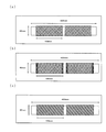
- a non-limiting example of such a gravure roll is shown in FIG. The example of the roll shown in FIG.
- 1B is a roll-shaped cell having a roll diameter of 60 mm, a roll width of 400 mm, and a cell depth Tc at the end of the engraving portion: 240 ⁇ m, a cell volume of 100 cm 3 / m 2 , The cell depth Td at the center is 260 ⁇ m, and the cell volume is 110 cm 3 / m 2 .
- a preferable range of the cell depth Tc at the end of the engraving portion Z corresponding to at least one coating layer laminate portion X in the film width direction of the gravure roll to be used is a coating solution (dispersion) concentration described later.
- a coating solution (dispersion) concentration described later.
- the type of the plate laminate type, oblique line type, etc.
- the oblique line type it is 30 to 180 ⁇ m, more preferably 50 to 150 ⁇ m
- the preferred range of the cell depth Td in the center is 50 to 200 ⁇ m More preferably, it is 70 to 220 ⁇ m.
- the preferable range of the cell volume Tcv at the end is 15 to 80 cm 3 / m 2 , more preferably 30 to 60 cm 3 / m 2 , depending on the concentration of the coating liquid (dispersion) as well as the depth.
- a preferable range of the cell volume Tdv at the center is 30 to 100 cm 3 / m 2 , more preferably 40 to 120 cm 3 / m 2 .
- the thickness is 40 to 320 ⁇ m, more preferably 80 to 300 ⁇ m
- the preferable range of the cell depth Td in the center is 60 to 430 ⁇ m, more preferably 80 to 400 ⁇ m.
- the preferable range of the cell volume Tcv at the end is 15 to 150 cm 3 / m 2 , more preferably 40 to 120 cm 3 / m 2 , although it depends on the coating liquid (dispersion) concentration as well as the depth.
- a preferable range of the cell volume Tdv at the center is 25 to 190 cm 3 / m 2 , more preferably 40 to 160 cm 3 / m 2 .
- a heat-resistant layer containing a filler and a resin binder is particularly preferable.
- the heat-resistant layer is a porous film formed by coating (applying) a surface of the polyolefin resin porous film with a filler-containing resin solution (dispersion) in which a filler and a resin binder are dissolved or dispersed in a solvent. Can be formed on the surface.
- Filler examples of the filler that can be used in the present invention include an inorganic filler and an organic filler, but are not particularly limited.
- inorganic fillers include carbonates such as calcium carbonate, magnesium carbonate and barium carbonate; sulfates such as calcium sulfate, magnesium sulfate and barium sulfate; chlorides such as sodium chloride, calcium chloride and magnesium chloride, aluminum oxide and oxidation
- oxides such as calcium, magnesium oxide, zinc oxide, titanium oxide, and silica
- silicates such as talc, clay, and mica can be used.
- barium sulfate and aluminum oxide are preferable.
- organic fillers include ultra high molecular weight polyethylene, polystyrene, polymethyl methacrylate, polycarbonate, polyethylene terephthalate, polybutylene terephthalate, polyphenylene sulfide, polysulfone, polyethersulfone, polyetheretherketone, polytetrafluoroethylene, polyimide, polyether.
- examples thereof include thermoplastic resins such as imide, melamine, and benzoguanamine, and thermosetting resins. Among these, cross-linked polystyrene and the like are particularly preferable.
- the average particle size of the filler is preferably 0.1 ⁇ m or more, more preferably 0.2 ⁇ m or more, still more preferably 0.3 ⁇ m or more, and the upper limit is preferably 3.0 ⁇ m or less, more preferably 1.5 ⁇ m or less. It is. Setting the average particle size to 0.1 ⁇ m or more is preferable from the viewpoint of reducing the shrinkage rate of the laminated porous film to make it difficult to break the film and from the viewpoint of realizing heat resistance. On the other hand, setting the average particle size to 3.0 ⁇ m or less is preferable from the viewpoint of reducing the shrinkage rate of the laminated porous film and making it difficult to break the membrane.
- an average particle diameter shall be 1.5 micrometers or less from a viewpoint of forming a porous layer with small layer thickness favorably, and the viewpoint of the dispersibility in the porous layer of an inorganic filler.
- the “average particle diameter of the inorganic filler” is a value measured according to a method using SEM.
- the ratio of the filler to the total amount of the filler and the resin binder (hereinafter referred to as “F%”) is preferably 92% by mass or more, more preferably 95% by mass or more, and 98% by mass. The above is more preferable. If the F% is 92% by mass or more, it is preferable because a laminated porous film having connectivity can be produced and excellent air permeation performance can be exhibited.
- the filler, the polyolefin-based resin porous film can be satisfactorily bonded, is electrochemically stable, and a laminated porous film is used as a battery separator.
- a laminated porous film is used as a battery separator.
- ethylene-acrylic acid copolymers such as ethylene-vinyl acetate copolymers (EVA, structural units derived from vinyl acetate of 20 to 35 mol%), ethylene-ethyl acrylate copolymers, fluororesins [Polyvinylidene fluoride (PVDF), polyvinylidene fluoride-hexafluoropropylene, polyvinylidene fluoride-trichloroethylene, etc.], fluorinated rubber, styrene-butadiene rubber (SBR), nitrile butadiene rubber (NBR), polybutadiene rubber (BR), poly Acrylonitrile (PAN), polyacrylic acid (PAA), carboxymethyl cellulose (CMC), hydroxyethyl cellulose (HEC), polyvinyl alcohol (PVA), cyanoethyl polyvinyl alcohol, polyvinyl butyral (PVB), polyvinyl chloride Rupiroridon (PVP), polyviny
- organic binders may be used alone or in combination of two or more.
- polyvinyl alcohol, polyvinylidene fluoride, styrene-butadiene rubber, carboxymethyl cellulose, and polyacrylic acid are preferable.
- a filler-containing resin solution in which the filler and the resin binder are dissolved or dispersed in a solvent is coated (applied) on the surface of the polyolefin resin porous film that has been surface-treated.
- a heat-resistant layer can be formed on the surface of the porous film.
- the solvent it is preferable to use a solvent in which the filler and the resin binder can be dissolved or dispersed uniformly and stably.
- a solvent include N-methylpyrrolidone, N, N-dimethylformamide, N, N-dimethylacetamide, water, ethanol, toluene, hot xylene, and hexane.
- the dispersion liquid contains a dispersant such as a surfactant, a thickener, a wetting agent, a disinfectant.
- additives such as foaming agents, pH adjusting agents including acids and alkalis, and the like may be added. These additives are preferably those that can be removed upon solvent removal or plasticizer extraction, but are electrochemically stable in the range of use of the lithium ion secondary battery, do not inhibit the battery reaction, and are up to about 200 ° C. If stable, it may remain in the battery (in the laminated porous film).
- Examples of a method for dissolving or dispersing the filler and the resin binder in a solvent include, for example, a ball mill, a bead mill, a planetary ball mill, a vibrating ball mill, a sand mill, a colloid mill, an attritor, a roll mill, a high-speed impeller dispersion, a disperser, a homogenizer, and a high-speed Examples thereof include an impact mill, ultrasonic dispersion, a mechanical stirring method using stirring blades, and the like.
- the solvent is preferably a solvent that can be removed from the dispersion applied to the polyolefin resin porous film.
- a method for removing the solvent any method that does not adversely affect the polyolefin resin porous film can be adopted without any particular limitation.
- a method for removing the solvent for example, a method in which a polyolefin resin porous film is fixed and dried at a temperature below its melting point, a method in which drying is performed at a low temperature under reduced pressure, or a resin binder is solidified by being immersed in a poor solvent for the resin binder. And a method of extracting the solvent at the same time.
- the heat-resistant layer can be formed in-line, but after the surface treatment, the porous film is wound up and offline in a separate process.
- a heat-resistant layer can also be formed.
- the total thickness of the laminated porous film obtained using the production method of the present invention is preferably 5 to 100 ⁇ m. More preferably, it is 8 to 50 ⁇ m, and still more preferably 10 to 30 ⁇ m.
- it is used as a battery separator, if it is 5 ⁇ m or more, substantially necessary electrical insulation can be obtained. For example, even when a large force is applied to the protruding portion of the electrode, the battery separator is broken and short-circuited. It is difficult and safe.
- the electrical resistance of a laminated porous film can be made small if a film thickness is 100 micrometers or less, the performance of a battery can fully be ensured.
- the porosity is preferably 30% to 70% as described above, and if it is 30% or more, it is possible to obtain a laminated porous film that secures communication and has excellent air permeability. Moreover, if it is 70% or less, the intensity
- the laminated porous film of the present invention has an air permeability measured in accordance with JIS P8117 of 2000 seconds / 100 ml or less.
- the air permeability after heating at 135 ° C. for 5 seconds is set to 10,000 seconds / 100 ml or more, and the pores are quickly closed when abnormal heat is generated. It shuts off so that troubles such as battery rupture can be avoided.
- a nonaqueous electrolyte battery containing the laminated porous film of the present invention as a battery separator will be described with reference to FIG.
- Both electrodes of the positive electrode plate 21 and the negative electrode plate 22 are wound in a spiral shape so as to overlap each other via the battery separator 10, and the outside is stopped with a winding tape to form a wound body.
- the wound body in which the positive electrode plate 21, the battery separator 10 and the negative electrode plate 22 are integrally wound is accommodated in a bottomed cylindrical battery case and welded to the positive and negative electrode lead bodies 24 and 25.
- the electrolyte is injected into the battery can, and after the electrolyte has sufficiently penetrated into the battery separator 10 or the like, the positive electrode lid 27 is sealed around the opening periphery of the battery can via the gasket 26, and precharging and aging are performed.
- a secondary battery 20 made of a cylindrical nonaqueous electrolyte battery is produced.
- an electrolytic solution in which a lithium salt is used as an electrolyte and this is dissolved in an organic solvent is used.
- the organic solvent is not particularly limited.
- esters such as propylene carbonate, ethylene carbonate, butylene carbonate, ⁇ -butyrolactone, ⁇ -valerolactone, dimethyl carbonate, methyl propionate or butyl acetate, and nitriles such as acetonitrile.
- ethers such as tetrahydrofuran, 2-methyltetrahydrofuran or 4-methyl-1,3-dioxolane, or sulfolane.
- LiPF 6 lithium hexafluorophosphate
- an alkali metal or a compound containing an alkali metal integrated with a current collecting material such as a stainless steel net is used.
- the alkali metal include lithium, sodium, and potassium.
- the compound containing an alkali metal include an alloy of an alkali metal and aluminum, lead, indium, potassium, cadmium, tin or magnesium, a compound of an alkali metal and a carbon material, a low potential alkali metal and a metal oxide, and the like. Or a compound with a sulfide or the like.
- the carbon material may be any material that can be doped and dedoped with lithium ions, such as graphite, pyrolytic carbons, cokes, glassy carbons, a fired body of an organic polymer compound, Mesocarbon microbeads, carbon fibers, activated carbon and the like can be used.
- a carbon material having an average particle size of 10 ⁇ m is mixed with a solution in which vinylidene fluoride is dissolved in N-methylpyrrolidone to form a slurry, and this negative electrode mixture slurry is passed through a 70-mesh net. After removing the large particles, uniformly apply to both sides of the negative electrode current collector made of a strip-shaped copper foil having a thickness of 18 ⁇ m and dry, and then compression-molded with a roll press machine, cut, strip-shaped negative electrode plate and We use what we did.
- lithium cobalt oxide, lithium nickel oxide, lithium manganese oxide, manganese dioxide, metal oxide such as vanadium pentoxide or chromium oxide, metal sulfide such as molybdenum disulfide, etc. are used as active materials.
- These positive electrode active materials are combined with conductive additives and binders such as polytetrafluoroethylene as appropriate, and finished with a current collector material such as a stainless steel mesh as a core material. It is done.
- a strip-like positive electrode plate produced as follows is used as the positive electrode. That is, lithium graphite oxide (LiCoO 2 ) is added with phosphorous graphite as a conductive additive at a mass ratio of 90: 5 (lithium cobalt oxide: phosphorous graphite) and mixed, and this mixture and polyvinylidene fluoride are mixed with N Mix with a solution in methylpyrrolidone to make a slurry.
- This positive electrode mixture slurry is passed through a 70-mesh net to remove large particles, and then uniformly applied to both sides of a positive electrode current collector made of an aluminum foil having a thickness of 20 ⁇ m, dried, and then compressed by a roll press. After forming, it is cut into a strip-like positive electrode plate.
- polypropylene resin (Prime Polymer Co., Prime Polypro F300SV, density: 0.90 g / cm 3 , MFR: 3.0 g / 10 min) and ⁇ crystal nucleating agent 3,9-bis [4 -(N-cyclohexylcarbamoyl) phenyl] -2,4,8,10-tetraoxaspiro [5.5] undecane was prepared.
- Each raw material is blended at a ratio of 0.2 part by mass of ⁇ -crystal nucleating agent with respect to 100 parts by mass of polypropylene resin, and the same direction twin screw extruder manufactured by Toshiba Machine Co., Ltd.
- polypropylene resin composition pellets (caliber: 40 mm ⁇ , L / D: 32), melted and mixed at a preset temperature of 300 ° C., cooled and solidified in a water bath, cut into strands with a pelletizer, and produced polypropylene resin composition pellets.
- the ⁇ activity of the polypropylene resin composition was 80%.
- glycerin is added to 100 parts by mass of high-density polyethylene (manufactured by Nippon Polytechnics, Novatec HD HF560, density: 0.963 g / cm 3 , MFR: 7.0 g / 10 min).
- the resulting porous film made of polyolefin resin was prepared using a corona treatment device (Kasuga Denki Co., Ltd., aluminum 5 type electrode, 2 ridges x 6, line speed: 50 m / min, treatment output: 1.5 kW), Corona surface treatment was performed under the conditions of the following examples.
- Coating fluid for heat-resistant layer Alumina (Sumitomo Chemical Co., Sumiko Random AA-03, average particle size: 0.3 ⁇ m) 39.2 parts by mass, polyvinyl alcohol (Kuraray Co., Ltd., PVA120, saponification degree: 98.0 to 99.0, average polymerization degree) : 2000) A dispersion in which 0.8 part by mass was dispersed in 60.0 parts by mass of water was obtained.
- Example 1 A gravure roll (roll diameter 60 mm, roll width 400 mm, lattice type, cell depth 260 ⁇ m, cell volume 110 cm 3 / m 2 ) shown in FIG. 1A is applied to the base material (350 mm width) of the polyolefin resin porous film.
- the coating solution was continuously coated by a kiss reverse gravure coating method to form a coating layer, and a 1000 m film roll was prepared.
- the film thickness Ta at the end of the coating layer laminated portion and the film thickness Tb at the center satisfy the relational expression of Ta ⁇ Tb and the case where the relational expression is not satisfied.
- Comparative Example 1 in which the so-called ear height was increased it was confirmed that a significant difference occurred in the generation of wrinkles.
Landscapes
- Chemical & Material Sciences (AREA)
- Chemical Kinetics & Catalysis (AREA)
- Electrochemistry (AREA)
- General Chemical & Material Sciences (AREA)
- Engineering & Computer Science (AREA)
- Manufacturing & Machinery (AREA)
- Laminated Bodies (AREA)
- Cell Separators (AREA)
- Manufacture Of Porous Articles, And Recovery And Treatment Of Waste Products (AREA)
Abstract
Cette invention concerne un rouleau de film poreux stratifié qui est un film poreux stratifié comprenant une couche de couverture partiellement stratifiée sur au moins une surface d'un film poreux en résine polyoléfine qui comporte une ligne de démarcation formée linéairement entre la partie où la couche de couverture est stratifiée (partie avec couche de couverture) et la partie où la couche de couverture n'est pas stratifiée (partie sans couche de couverture). Il peut être enroulé sans former de plis, est de qualité uniforme, et présente une aptitude à la mise en œuvre secondaire améliorée pour formation de fentes, etc. Le rouleau de film poreux stratifié selon l'invention comprend une couche de couverture partiellement stratifiée sur au moins une surface d'un film poreux en résine polyoléfine, et comprend au moins une partie X avec couche de couverture et au moins une partie Y sans couche de couverture, l'épaisseur de film Ta à la partie d'extrémité de ladite au moins partie X avec couche de couverture et l'épaisseur de film Tb dans la partie centrale satisfaisant l'expression relationnelle Ta ≦ Tb, et la longueur d'enroulement du film étant de 1000 m ou plus.
Applications Claiming Priority (4)
| Application Number | Priority Date | Filing Date | Title |
|---|---|---|---|
| JP2011-264768 | 2011-12-02 | ||
| JP2011264768 | 2011-12-02 | ||
| JP2012130651 | 2012-06-08 | ||
| JP2012-130651 | 2012-06-08 |
Publications (1)
| Publication Number | Publication Date |
|---|---|
| WO2013080701A1 true WO2013080701A1 (fr) | 2013-06-06 |
Family
ID=48535172
Family Applications (1)
| Application Number | Title | Priority Date | Filing Date |
|---|---|---|---|
| PCT/JP2012/077222 Ceased WO2013080701A1 (fr) | 2011-12-02 | 2012-10-22 | Rouleau de film poreux stratifié et son procédé de fabrication |
Country Status (2)
| Country | Link |
|---|---|
| JP (2) | JPWO2013080701A1 (fr) |
| WO (1) | WO2013080701A1 (fr) |
Cited By (10)
| Publication number | Priority date | Publication date | Assignee | Title |
|---|---|---|---|---|
| WO2016031990A1 (fr) * | 2014-08-29 | 2016-03-03 | 住友化学株式会社 | Corps enroulé de film poreux et son procédé de fabrication |
| JP2016042446A (ja) * | 2014-08-19 | 2016-03-31 | 東レバッテリーセパレータフィルム株式会社 | ポリオレフィン微多孔膜捲回体 |
| WO2017018483A1 (fr) * | 2015-07-29 | 2017-02-02 | 東レバッテリーセパレータフィルム株式会社 | Séparateur de batterie et son procédé de fabrication |
| JP6105185B1 (ja) * | 2015-10-09 | 2017-03-29 | 東レバッテリーセパレータフィルム株式会社 | 積層ポリオレフィン微多孔膜、電池用セパレータおよびそれらの製造方法 |
| WO2017094486A1 (fr) * | 2015-12-04 | 2017-06-08 | 東レ株式会社 | Séparateur de batterie et procédé de fabrication de ce dernier |
| WO2017110306A1 (fr) * | 2015-12-24 | 2017-06-29 | 東レ株式会社 | Membrane microporeuse en polyoléfine, séparateur de batterie et procédé de production de ces derniers |
| CN107925034A (zh) * | 2015-08-27 | 2018-04-17 | 东丽株式会社 | 电池用隔膜及其制造方法 |
| EP3493296A4 (fr) * | 2016-07-28 | 2020-04-29 | Toray Industries, Inc. | Corps enroulé multicouche |
| TWI716496B (zh) * | 2016-11-21 | 2021-01-21 | 日商東麗股份有限公司 | 電池用隔膜及其製造方法以及電池用隔膜之捲繞體 |
| CN114364534A (zh) * | 2019-09-06 | 2022-04-15 | 东洋纺株式会社 | 燃料电池用层叠体 |
Families Citing this family (6)
| Publication number | Priority date | Publication date | Assignee | Title |
|---|---|---|---|---|
| KR20230007535A (ko) | 2014-07-11 | 2023-01-12 | 데이진 가부시키가이샤 | 세퍼레이터 롤의 제조 방법 |
| US9931756B2 (en) | 2014-12-25 | 2018-04-03 | Sumitomo Chemical Company, Limited | Method for producing separator and method for slitting |
| JP6740570B2 (ja) * | 2015-05-29 | 2020-08-19 | 住友化学株式会社 | 積層フィルム及び積層フィルムの製造方法 |
| JP2017064704A (ja) * | 2015-10-02 | 2017-04-06 | 住友化学株式会社 | 塗工方法、塗工装置、および機能性フィルムの製造方法 |
| KR102218546B1 (ko) | 2017-12-26 | 2021-02-19 | 주식회사 엘지화학 | 그라비어 코팅 장치 |
| KR102845525B1 (ko) * | 2021-08-11 | 2025-08-11 | 주식회사 엘지에너지솔루션 | 이차전지용 셀 및 이의 제조 방법 |
Citations (10)
| Publication number | Priority date | Publication date | Assignee | Title |
|---|---|---|---|---|
| JPS6175870U (fr) * | 1984-10-19 | 1986-05-22 | ||
| JPH0161968U (fr) * | 1987-10-12 | 1989-04-20 | ||
| JPH0721558A (ja) * | 1993-06-30 | 1995-01-24 | Sony Corp | 磁気記録媒体の製造方法 |
| JPH115052A (ja) * | 1997-06-16 | 1999-01-12 | Toppan Printing Co Ltd | グラビア塗工版 |
| JP2002301411A (ja) * | 2001-04-03 | 2002-10-15 | Osg Corp | 塗工用ロッド、およびその製造方法 |
| JP2007273126A (ja) * | 2006-03-30 | 2007-10-18 | Matsushita Electric Ind Co Ltd | 多孔質耐熱層の形成方法および多孔質耐熱層の形成装置 |
| JP2009028719A (ja) * | 2007-07-05 | 2009-02-12 | Toyota Motor Corp | 塗布装置 |
| WO2011062285A1 (fr) * | 2009-11-20 | 2011-05-26 | 三菱樹脂株式会社 | Film poreux stratifié, séparateur pour batterie, et batterie |
| JP2011159434A (ja) * | 2010-01-29 | 2011-08-18 | Toyota Motor Corp | セパレータとその製造方法 |
| JP2011194381A (ja) * | 2010-03-24 | 2011-10-06 | Toray Advanced Film Co Ltd | グラビアロール及び塗布方法 |
-
2012
- 2012-10-22 JP JP2012550652A patent/JPWO2013080701A1/ja active Pending
- 2012-10-22 WO PCT/JP2012/077222 patent/WO2013080701A1/fr not_active Ceased
-
2013
- 2013-03-14 JP JP2013051924A patent/JP2014012391A/ja active Pending
Patent Citations (10)
| Publication number | Priority date | Publication date | Assignee | Title |
|---|---|---|---|---|
| JPS6175870U (fr) * | 1984-10-19 | 1986-05-22 | ||
| JPH0161968U (fr) * | 1987-10-12 | 1989-04-20 | ||
| JPH0721558A (ja) * | 1993-06-30 | 1995-01-24 | Sony Corp | 磁気記録媒体の製造方法 |
| JPH115052A (ja) * | 1997-06-16 | 1999-01-12 | Toppan Printing Co Ltd | グラビア塗工版 |
| JP2002301411A (ja) * | 2001-04-03 | 2002-10-15 | Osg Corp | 塗工用ロッド、およびその製造方法 |
| JP2007273126A (ja) * | 2006-03-30 | 2007-10-18 | Matsushita Electric Ind Co Ltd | 多孔質耐熱層の形成方法および多孔質耐熱層の形成装置 |
| JP2009028719A (ja) * | 2007-07-05 | 2009-02-12 | Toyota Motor Corp | 塗布装置 |
| WO2011062285A1 (fr) * | 2009-11-20 | 2011-05-26 | 三菱樹脂株式会社 | Film poreux stratifié, séparateur pour batterie, et batterie |
| JP2011159434A (ja) * | 2010-01-29 | 2011-08-18 | Toyota Motor Corp | セパレータとその製造方法 |
| JP2011194381A (ja) * | 2010-03-24 | 2011-10-06 | Toray Advanced Film Co Ltd | グラビアロール及び塗布方法 |
Cited By (27)
| Publication number | Priority date | Publication date | Assignee | Title |
|---|---|---|---|---|
| JP2016042446A (ja) * | 2014-08-19 | 2016-03-31 | 東レバッテリーセパレータフィルム株式会社 | ポリオレフィン微多孔膜捲回体 |
| US10059085B2 (en) | 2014-08-29 | 2018-08-28 | Sumitomo Chemical Company, Limited | Wound body of porous film, and manufacturing method thereof |
| JPWO2016031990A1 (ja) * | 2014-08-29 | 2017-04-27 | 住友化学株式会社 | 多孔質フィルムの捲回体、および、その製造方法 |
| JP2017022092A (ja) * | 2014-08-29 | 2017-01-26 | 住友化学株式会社 | 多孔質フィルムの捲回体、および、その製造方法 |
| WO2016031990A1 (fr) * | 2014-08-29 | 2016-03-03 | 住友化学株式会社 | Corps enroulé de film poreux et son procédé de fabrication |
| WO2017018483A1 (fr) * | 2015-07-29 | 2017-02-02 | 東レバッテリーセパレータフィルム株式会社 | Séparateur de batterie et son procédé de fabrication |
| CN107925034A (zh) * | 2015-08-27 | 2018-04-17 | 东丽株式会社 | 电池用隔膜及其制造方法 |
| KR20180041137A (ko) * | 2015-08-27 | 2018-04-23 | 도레이 카부시키가이샤 | 전지용 세퍼레이터 및 그 제조방법 |
| KR102187519B1 (ko) * | 2015-08-27 | 2020-12-07 | 도레이 카부시키가이샤 | 전지용 세퍼레이터 및 그 제조방법 |
| CN107431166A (zh) * | 2015-10-09 | 2017-12-01 | 东丽株式会社 | 积层聚烯烃微多孔膜、电池用隔离膜及其制造方法 |
| WO2017061489A1 (fr) * | 2015-10-09 | 2017-04-13 | 東レバッテリーセパレータフィルム株式会社 | Membrane microporeuse en polyoléfine multicouche, séparateur pour batteries, et procédés de fabrication de celui-ci |
| JP6105185B1 (ja) * | 2015-10-09 | 2017-03-29 | 東レバッテリーセパレータフィルム株式会社 | 積層ポリオレフィン微多孔膜、電池用セパレータおよびそれらの製造方法 |
| EP3211693A4 (fr) * | 2015-10-09 | 2018-08-29 | Toray Industries, Inc. | Membrane microporeuse en polyoléfine multicouche, séparateur pour batteries, et procédés de fabrication de celui-ci |
| US10283749B2 (en) | 2015-10-09 | 2019-05-07 | Toray Industries, Inc. | Laminated polyolefin microporous membrane, battery separator, and production method thereof |
| WO2017094486A1 (fr) * | 2015-12-04 | 2017-06-08 | 東レ株式会社 | Séparateur de batterie et procédé de fabrication de ce dernier |
| JPWO2017094486A1 (ja) * | 2015-12-04 | 2018-09-27 | 東レ株式会社 | 電池用セパレータおよびその製造方法 |
| US10770707B2 (en) | 2015-12-04 | 2020-09-08 | Toray Industries, Inc. | Battery separator and method of manufacturing same |
| TWI717431B (zh) * | 2015-12-04 | 2021-02-01 | 日商東麗股份有限公司 | 電池用隔膜及其製備方法以及電池用隔膜的捲繞體 |
| TWI720088B (zh) * | 2015-12-24 | 2021-03-01 | 日商東麗股份有限公司 | 電池用隔膜及其製備方法以及電池用隔膜捲繞體的製備方法 |
| JPWO2017110306A1 (ja) * | 2015-12-24 | 2018-10-11 | 東レ株式会社 | ポリオレフィン微多孔膜、電池用セパレータおよびそれらの製造方法 |
| WO2017110306A1 (fr) * | 2015-12-24 | 2017-06-29 | 東レ株式会社 | Membrane microporeuse en polyoléfine, séparateur de batterie et procédé de production de ces derniers |
| US10978721B2 (en) | 2015-12-24 | 2021-04-13 | Toray Industries, Inc. | Polyolefin microporous membrane, battery separator and production method |
| TWI716618B (zh) * | 2016-07-28 | 2021-01-21 | 日商東麗股份有限公司 | 積層捲繞體 |
| EP3493296A4 (fr) * | 2016-07-28 | 2020-04-29 | Toray Industries, Inc. | Corps enroulé multicouche |
| TWI716496B (zh) * | 2016-11-21 | 2021-01-21 | 日商東麗股份有限公司 | 電池用隔膜及其製造方法以及電池用隔膜之捲繞體 |
| CN114364534A (zh) * | 2019-09-06 | 2022-04-15 | 东洋纺株式会社 | 燃料电池用层叠体 |
| CN114364534B (zh) * | 2019-09-06 | 2023-06-27 | 东洋纺株式会社 | 燃料电池用层叠体 |
Also Published As
| Publication number | Publication date |
|---|---|
| JPWO2013080701A1 (ja) | 2015-04-27 |
| JP2014012391A (ja) | 2014-01-23 |
Similar Documents
| Publication | Publication Date | Title |
|---|---|---|
| JP5265052B1 (ja) | 積層多孔フィルムの製造方法 | |
| JP5676577B2 (ja) | 積層多孔フィルム、非水電解液二次電池用セパレータ、および非水電解液二次電池 | |
| WO2013080701A1 (fr) | Rouleau de film poreux stratifié et son procédé de fabrication | |
| JP5502707B2 (ja) | 積層多孔フィルム、電池用セパレータおよび電池 | |
| JP5419817B2 (ja) | 積層多孔フィルム、非水電解液二次電池用セパレータ、および非水電解液二次電池 | |
| JP5298247B2 (ja) | 積層多孔フィルム、電池用セパレータおよび電池 | |
| JP5690832B2 (ja) | 積層多孔フィルム、非水電解液二次電池用セパレータ、および非水電解液二次電池 | |
| JP5697328B2 (ja) | 積層多孔フィルム、電池用セパレータ、および電池 | |
| JP4734397B2 (ja) | 積層多孔性フィルム、それを利用したリチウムイオン電池用セパレータ、および電池 | |
| WO2014002701A1 (fr) | Film poreux laminé, séparateur pour batterie secondaire à électrolyte non aqueux, et batterie secondaire à électrolyte non aqueux | |
| WO2012102241A1 (fr) | Film poreux en résine polyoléfine, et séparateur pour cellule à électrolyte non aqueux l'utilisant | |
| JP4801706B2 (ja) | セパレータ用積層多孔性フィルム、およびその製造方法 | |
| JP4801705B2 (ja) | セパレータ用積層多孔性フィルム、およびその製造方法 | |
| JP5885104B2 (ja) | 積層多孔フィルム、非水電解液二次電池用セパレータ、及び非水電解液二次電池 | |
| JP5976305B2 (ja) | 積層多孔フィルムの製造方法 | |
| JP5848193B2 (ja) | 積層多孔フィルム、非水電解液二次電池用セパレータ、及び非水電解液二次電池 | |
| JP2013116442A (ja) | 積層多孔フィルムの製造方法 |
Legal Events
| Date | Code | Title | Description |
|---|---|---|---|
| ENP | Entry into the national phase |
Ref document number: 2012550652 Country of ref document: JP Kind code of ref document: A |
|
| 121 | Ep: the epo has been informed by wipo that ep was designated in this application |
Ref document number: 12853378 Country of ref document: EP Kind code of ref document: A1 |
|
| NENP | Non-entry into the national phase |
Ref country code: DE |
|
| 122 | Ep: pct application non-entry in european phase |
Ref document number: 12853378 Country of ref document: EP Kind code of ref document: A1 |