WO2013084307A1 - 内燃機関の排気浄化装置 - Google Patents
内燃機関の排気浄化装置 Download PDFInfo
- Publication number
- WO2013084307A1 WO2013084307A1 PCT/JP2011/078237 JP2011078237W WO2013084307A1 WO 2013084307 A1 WO2013084307 A1 WO 2013084307A1 JP 2011078237 W JP2011078237 W JP 2011078237W WO 2013084307 A1 WO2013084307 A1 WO 2013084307A1
- Authority
- WO
- WIPO (PCT)
- Prior art keywords
- temperature
- catalyst
- fuel ratio
- air
- degree
- Prior art date
- Legal status (The legal status is an assumption and is not a legal conclusion. Google has not performed a legal analysis and makes no representation as to the accuracy of the status listed.)
- Ceased
Links
Images



Classifications
-
- F—MECHANICAL ENGINEERING; LIGHTING; HEATING; WEAPONS; BLASTING
- F01—MACHINES OR ENGINES IN GENERAL; ENGINE PLANTS IN GENERAL; STEAM ENGINES
- F01N—GAS-FLOW SILENCERS OR EXHAUST APPARATUS FOR MACHINES OR ENGINES IN GENERAL; GAS-FLOW SILENCERS OR EXHAUST APPARATUS FOR INTERNAL-COMBUSTION ENGINES
- F01N9/00—Electrical control of exhaust gas treating apparatus
-
- F—MECHANICAL ENGINEERING; LIGHTING; HEATING; WEAPONS; BLASTING
- F01—MACHINES OR ENGINES IN GENERAL; ENGINE PLANTS IN GENERAL; STEAM ENGINES
- F01N—GAS-FLOW SILENCERS OR EXHAUST APPARATUS FOR MACHINES OR ENGINES IN GENERAL; GAS-FLOW SILENCERS OR EXHAUST APPARATUS FOR INTERNAL-COMBUSTION ENGINES
- F01N11/00—Monitoring or diagnostic devices for exhaust-gas treatment apparatus
-
- F—MECHANICAL ENGINEERING; LIGHTING; HEATING; WEAPONS; BLASTING
- F01—MACHINES OR ENGINES IN GENERAL; ENGINE PLANTS IN GENERAL; STEAM ENGINES
- F01N—GAS-FLOW SILENCERS OR EXHAUST APPARATUS FOR MACHINES OR ENGINES IN GENERAL; GAS-FLOW SILENCERS OR EXHAUST APPARATUS FOR INTERNAL-COMBUSTION ENGINES
- F01N11/00—Monitoring or diagnostic devices for exhaust-gas treatment apparatus
- F01N11/007—Monitoring or diagnostic devices for exhaust-gas treatment apparatus the diagnostic devices measuring oxygen or air concentration downstream of the exhaust apparatus
-
- F—MECHANICAL ENGINEERING; LIGHTING; HEATING; WEAPONS; BLASTING
- F02—COMBUSTION ENGINES; HOT-GAS OR COMBUSTION-PRODUCT ENGINE PLANTS
- F02D—CONTROLLING COMBUSTION ENGINES
- F02D41/00—Electrical control of supply of combustible mixture or its constituents
- F02D41/02—Circuit arrangements for generating control signals
- F02D41/04—Introducing corrections for particular operating conditions
- F02D41/12—Introducing corrections for particular operating conditions for deceleration
- F02D41/123—Introducing corrections for particular operating conditions for deceleration the fuel injection being cut-off
-
- B—PERFORMING OPERATIONS; TRANSPORTING
- B01—PHYSICAL OR CHEMICAL PROCESSES OR APPARATUS IN GENERAL
- B01D—SEPARATION
- B01D2255/00—Catalysts
- B01D2255/10—Noble metals or compounds thereof
- B01D2255/102—Platinum group metals
- B01D2255/1025—Rhodium
-
- B—PERFORMING OPERATIONS; TRANSPORTING
- B01—PHYSICAL OR CHEMICAL PROCESSES OR APPARATUS IN GENERAL
- B01D—SEPARATION
- B01D2255/00—Catalysts
- B01D2255/20—Metals or compounds thereof
- B01D2255/209—Other metals
- B01D2255/2092—Aluminium
-
- B—PERFORMING OPERATIONS; TRANSPORTING
- B01—PHYSICAL OR CHEMICAL PROCESSES OR APPARATUS IN GENERAL
- B01D—SEPARATION
- B01D53/00—Separation of gases or vapours; Recovering vapours of volatile solvents from gases; Chemical or biological purification of waste gases, e.g. engine exhaust gases, smoke, fumes, flue gases, aerosols
- B01D53/34—Chemical or biological purification of waste gases
- B01D53/92—Chemical or biological purification of waste gases of engine exhaust gases
- B01D53/94—Chemical or biological purification of waste gases of engine exhaust gases by catalytic processes
- B01D53/9445—Simultaneously removing carbon monoxide, hydrocarbons or nitrogen oxides making use of three-way catalysts [TWC] or four-way-catalysts [FWC]
-
- B—PERFORMING OPERATIONS; TRANSPORTING
- B01—PHYSICAL OR CHEMICAL PROCESSES OR APPARATUS IN GENERAL
- B01D—SEPARATION
- B01D53/00—Separation of gases or vapours; Recovering vapours of volatile solvents from gases; Chemical or biological purification of waste gases, e.g. engine exhaust gases, smoke, fumes, flue gases, aerosols
- B01D53/34—Chemical or biological purification of waste gases
- B01D53/92—Chemical or biological purification of waste gases of engine exhaust gases
- B01D53/94—Chemical or biological purification of waste gases of engine exhaust gases by catalytic processes
- B01D53/9495—Controlling the catalytic process
-
- F—MECHANICAL ENGINEERING; LIGHTING; HEATING; WEAPONS; BLASTING
- F01—MACHINES OR ENGINES IN GENERAL; ENGINE PLANTS IN GENERAL; STEAM ENGINES
- F01N—GAS-FLOW SILENCERS OR EXHAUST APPARATUS FOR MACHINES OR ENGINES IN GENERAL; GAS-FLOW SILENCERS OR EXHAUST APPARATUS FOR INTERNAL-COMBUSTION ENGINES
- F01N2430/00—Influencing exhaust purification, e.g. starting of catalytic reaction, filter regeneration, or the like, by controlling engine operating characteristics
- F01N2430/06—Influencing exhaust purification, e.g. starting of catalytic reaction, filter regeneration, or the like, by controlling engine operating characteristics by varying fuel-air ratio, e.g. by enriching fuel-air mixture
-
- F—MECHANICAL ENGINEERING; LIGHTING; HEATING; WEAPONS; BLASTING
- F01—MACHINES OR ENGINES IN GENERAL; ENGINE PLANTS IN GENERAL; STEAM ENGINES
- F01N—GAS-FLOW SILENCERS OR EXHAUST APPARATUS FOR MACHINES OR ENGINES IN GENERAL; GAS-FLOW SILENCERS OR EXHAUST APPARATUS FOR INTERNAL-COMBUSTION ENGINES
- F01N2550/00—Monitoring or diagnosing the deterioration of exhaust systems
- F01N2550/02—Catalytic activity of catalytic converters
-
- F—MECHANICAL ENGINEERING; LIGHTING; HEATING; WEAPONS; BLASTING
- F01—MACHINES OR ENGINES IN GENERAL; ENGINE PLANTS IN GENERAL; STEAM ENGINES
- F01N—GAS-FLOW SILENCERS OR EXHAUST APPARATUS FOR MACHINES OR ENGINES IN GENERAL; GAS-FLOW SILENCERS OR EXHAUST APPARATUS FOR INTERNAL-COMBUSTION ENGINES
- F01N2900/00—Details of electrical control or of the monitoring of the exhaust gas treating apparatus
- F01N2900/06—Parameters used for exhaust control or diagnosing
- F01N2900/16—Parameters used for exhaust control or diagnosing said parameters being related to the exhaust apparatus, e.g. particulate filter or catalyst
- F01N2900/1602—Temperature of exhaust gas apparatus
-
- F—MECHANICAL ENGINEERING; LIGHTING; HEATING; WEAPONS; BLASTING
- F01—MACHINES OR ENGINES IN GENERAL; ENGINE PLANTS IN GENERAL; STEAM ENGINES
- F01N—GAS-FLOW SILENCERS OR EXHAUST APPARATUS FOR MACHINES OR ENGINES IN GENERAL; GAS-FLOW SILENCERS OR EXHAUST APPARATUS FOR INTERNAL-COMBUSTION ENGINES
- F01N2900/00—Details of electrical control or of the monitoring of the exhaust gas treating apparatus
- F01N2900/06—Parameters used for exhaust control or diagnosing
- F01N2900/16—Parameters used for exhaust control or diagnosing said parameters being related to the exhaust apparatus, e.g. particulate filter or catalyst
- F01N2900/1624—Catalyst oxygen storage capacity
-
- F—MECHANICAL ENGINEERING; LIGHTING; HEATING; WEAPONS; BLASTING
- F02—COMBUSTION ENGINES; HOT-GAS OR COMBUSTION-PRODUCT ENGINE PLANTS
- F02D—CONTROLLING COMBUSTION ENGINES
- F02D41/00—Electrical control of supply of combustible mixture or its constituents
- F02D41/02—Circuit arrangements for generating control signals
- F02D41/021—Introducing corrections for particular conditions exterior to the engine
- F02D41/0235—Introducing corrections for particular conditions exterior to the engine in relation with the state of the exhaust gas treating apparatus
- F02D2041/0265—Introducing corrections for particular conditions exterior to the engine in relation with the state of the exhaust gas treating apparatus to decrease temperature of the exhaust gas treating apparatus
-
- F—MECHANICAL ENGINEERING; LIGHTING; HEATING; WEAPONS; BLASTING
- F02—COMBUSTION ENGINES; HOT-GAS OR COMBUSTION-PRODUCT ENGINE PLANTS
- F02D—CONTROLLING COMBUSTION ENGINES
- F02D2200/00—Input parameters for engine control
- F02D2200/02—Input parameters for engine control the parameters being related to the engine
- F02D2200/08—Exhaust gas treatment apparatus parameters
- F02D2200/0802—Temperature of the exhaust gas treatment apparatus
-
- F—MECHANICAL ENGINEERING; LIGHTING; HEATING; WEAPONS; BLASTING
- F02—COMBUSTION ENGINES; HOT-GAS OR COMBUSTION-PRODUCT ENGINE PLANTS
- F02N—STARTING OF COMBUSTION ENGINES; STARTING AIDS FOR SUCH ENGINES, NOT OTHERWISE PROVIDED FOR
- F02N2200/00—Parameters used for control of starting apparatus
- F02N2200/02—Parameters used for control of starting apparatus said parameters being related to the engine
- F02N2200/026—Catalyst temperature
-
- Y—GENERAL TAGGING OF NEW TECHNOLOGICAL DEVELOPMENTS; GENERAL TAGGING OF CROSS-SECTIONAL TECHNOLOGIES SPANNING OVER SEVERAL SECTIONS OF THE IPC; TECHNICAL SUBJECTS COVERED BY FORMER USPC CROSS-REFERENCE ART COLLECTIONS [XRACs] AND DIGESTS
- Y02—TECHNOLOGIES OR APPLICATIONS FOR MITIGATION OR ADAPTATION AGAINST CLIMATE CHANGE
- Y02T—CLIMATE CHANGE MITIGATION TECHNOLOGIES RELATED TO TRANSPORTATION
- Y02T10/00—Road transport of goods or passengers
- Y02T10/10—Internal combustion engine [ICE] based vehicles
- Y02T10/12—Improving ICE efficiencies
-
- Y—GENERAL TAGGING OF NEW TECHNOLOGICAL DEVELOPMENTS; GENERAL TAGGING OF CROSS-SECTIONAL TECHNOLOGIES SPANNING OVER SEVERAL SECTIONS OF THE IPC; TECHNICAL SUBJECTS COVERED BY FORMER USPC CROSS-REFERENCE ART COLLECTIONS [XRACs] AND DIGESTS
- Y02—TECHNOLOGIES OR APPLICATIONS FOR MITIGATION OR ADAPTATION AGAINST CLIMATE CHANGE
- Y02T—CLIMATE CHANGE MITIGATION TECHNOLOGIES RELATED TO TRANSPORTATION
- Y02T10/00—Road transport of goods or passengers
- Y02T10/10—Internal combustion engine [ICE] based vehicles
- Y02T10/40—Engine management systems
Definitions
- the present invention relates to an exhaust purification device for an internal combustion engine.
- Patent Document 1 discloses a catalyst for purifying components in exhaust gas discharged from a combustion chamber of an internal combustion engine.
- This catalyst has an active element (that is, an element for activating an oxidation reaction or a reduction reaction of a component in exhaust gas) and a composite oxide composed of a composite oxide supporting this active element.
- this catalyst has a property that the active element is dissolved in the composite oxide when the internal atmosphere is an oxidizing atmosphere, and the active element is precipitated from the composite oxide when the internal atmosphere is a reducing atmosphere. is doing.
- the catalyst purifying ability (that is, the ability of the catalyst to purify the components in the exhaust gas) is represented by the catalyst use time (that is, the total time that the catalyst has been used for purifying the components in the exhaust gas). It varies depending on the degree of catalyst use. Therefore, in order for the internal combustion engine to exhibit the desired performance, it is necessary to perform engine control (that is, control related to the internal combustion engine) in consideration of such a change in the catalyst purification capacity, or such a change in the catalyst purification capacity. Therefore, it is necessary to construct a control logic used for engine control. However, it can be said that execution of such engine control and construction of such control logic are complicated.
- an object of the present invention is to make engine control relatively simple, and to make it possible to construct control logic used for engine control relatively easily and to make the catalyst exhibit the desired purification ability.
- An object of the present invention is to provide an exhaust purification device for an internal combustion engine.
- the invention of the present application for achieving the above object is a catalyst for purifying components in exhaust gas, comprising an active element that activates an oxidation reaction or reduction reaction of a component in exhaust gas and a composite that carries the active element
- a catalyst having an oxide is provided in the exhaust passage, and the active element is contained in the composite when the temperature of the catalyst is equal to or higher than a predetermined solid solution temperature, which is a predetermined temperature, and the internal atmosphere of the catalyst is an oxidizing atmosphere.
- the present invention relates to an exhaust emission control device for an engine.
- the internal combustion engine when the internal combustion engine can execute the fuel supply stop control for stopping the supply of fuel to the combustion chamber, and the temperature of the catalyst is equal to or higher than the execution prohibition temperature that is a predetermined temperature.
- the degree of use of the catalyst is determined in advance.
- the execution prohibition temperature is set to a temperature lower than the reference temperature while the temperature is less than or equal to the degree.
- the internal combustion engine can execute fuel supply increase control in which the amount of fuel supplied to the combustion chamber is increased from a reference amount, and the execution permission is such that the temperature of the catalyst is a predetermined temperature.
- the catalyst in a case where execution of the fuel supply increase control is permitted when the temperature is equal to or higher than the temperature and execution of the fuel supply increase control is prohibited when the temperature of the catalyst is lower than the execution permission temperature. While the degree is equal to or lower than a predetermined degree, the execution permission temperature is set to a temperature higher than the reference temperature.
- the catalyst inflow exhaust air-fuel ratio (that is, the air-fuel ratio of the exhaust gas flowing into the catalyst) becomes an air-fuel ratio leaner than the stoichiometric air-fuel ratio, and as a result, the internal atmosphere of the catalyst Becomes an oxidizing atmosphere.
- the catalyst temperature is relatively high, aggregation of the composite oxide occurs, and as a result, the catalyst purification ability changes.
- the catalyst inflow exhaust air-fuel ratio becomes richer than the stoichiometric air-fuel ratio, and as a result, the internal atmosphere of the catalyst becomes a reducing atmosphere.
- the catalyst has the property that the active element is precipitated from the composite oxide when the catalyst temperature is equal to or higher than the predetermined deposition temperature, the catalyst temperature is equal to or higher than the predetermined deposition temperature, and the internal atmosphere of the catalyst is a reducing atmosphere.
- the active element is precipitated from the composite oxide. Therefore, the amount of the precipitated active element (that is, the active element precipitated from the composite oxide) changes, and as a result, the catalyst purification ability changes.
- the internal combustion engine in order to make the internal combustion engine exhibit its desired performance, it is used for engine control so that the internal combustion engine can exhibit its expected performance in consideration of changes in the catalyst purification capacity during engine operation. It is necessary to construct a control logic that can be controlled and to perform engine control. However, when the catalyst purification capacity changes due to the execution of the fuel supply stop control or the fuel supply increase control, it is very complicated to construct the control logic or perform the engine control as described above. It can be said. In addition, since the catalyst is not deteriorated while the degree of use of the catalyst is relatively small, the amount of the precipitated active element that determines the catalyst purification ability is set in order to make the catalyst exhibit the desired purification ability. There is no need to increase it. Therefore, it can be said that it is preferable not to change the amount of the precipitated active element as much as possible while the degree of use of the catalyst is relatively small.
- the execution of the fuel supply stop control is prohibited when the catalyst temperature is equal to or higher than the execution prohibition temperature, and the catalyst temperature is lower than the execution prohibition temperature.
- the execution prohibition temperature is higher than the reference temperature while the use degree of the catalyst is not more than a predetermined degree (that is, while the use degree of the catalyst is relatively small). Is also set to a lower temperature. According to this, since the opportunity for executing the fuel supply stop control is reduced, there is little opportunity for the aggregation of the composite oxide, and as a result, the change in the catalyst purification capability is small.
- the execution of the fuel supply increase control is permitted when the catalyst temperature is equal to or higher than the execution permission temperature, and the catalyst temperature is lower than the execution permission temperature.
- the execution permission temperature is higher than the reference temperature while the catalyst usage is below a predetermined level (that is, while the catalyst usage is relatively small). Set to high temperature. According to this, since the opportunity for executing the fuel supply increase control is reduced, the change in the amount of the precipitated active element is small, and as a result, the change in the catalyst purification capacity is also small.
- a control logic used for engine control can be constructed relatively easily while the catalyst usage is relatively small, and the engine can be engineered while the catalyst usage is relatively small. Control can be performed relatively easily and the catalyst can exhibit the desired purification ability.
- the execution prohibition temperature is set to a temperature higher than the reference temperature while the temperature is less than a second degree that is greater than the first degree and greater than the first degree.
- the execution prohibition temperature is set to a temperature higher than the reference temperature. According to this, since the opportunity for executing the fuel supply stop control increases, the aggregation of the complex oxide is promoted. For this reason, the effect that the precipitation rate of an active element can be reduced is acquired.
- the active element solid solubility that is, the ratio of the active element that is dissolved in the composite oxide among the active elements
- the target solid solubility that is, the target active element
- the activity is increased after the use degree of the catalyst is larger than the second degree.
- the active element solid solubility representing the proportion of the active element dissolved in the composite oxide among the elements flows into the catalyst so that the target solid solubility, which is the target active element solid solubility, is controlled.
- the air-fuel ratio of the exhaust gas is controlled to an air-fuel ratio leaner than the stoichiometric air-fuel ratio, or the air-fuel ratio of the exhaust gas flowing into the catalyst is controlled to be richer than the stoichiometric air-fuel ratio.
- the catalyst temperature becomes equal to or higher than a predetermined solid solution temperature or reaches a predetermined precipitation temperature.
- the catalyst inflow exhaust air-fuel ratio may be temporarily leaner than the stoichiometric air-fuel ratio or richer than the stoichiometric air-fuel ratio.
- the catalyst inflow exhaust air-fuel ratio becomes leaner than the stoichiometric air-fuel ratio when the catalyst temperature is equal to or higher than the predetermined solid solution temperature, the internal atmosphere of the catalyst becomes an oxidizing atmosphere.
- the active element When the active element has a property of being dissolved in the composite oxide when the temperature is higher than the solid solution temperature and the internal atmosphere of the catalyst is an oxidizing atmosphere, the active element is dissolved in the composite oxide.
- the catalyst inflow exhaust air-fuel ratio becomes richer than the stoichiometric air-fuel ratio when the catalyst temperature is equal to or higher than the predetermined deposition temperature, the internal atmosphere of the catalyst becomes a reducing atmosphere.
- the active element has the property of precipitating from the composite oxide when the internal atmosphere of the catalyst is a reducing atmosphere, the active element is precipitated from the composite oxide.
- the amount of the precipitated active element changes due to the change in the catalyst temperature and the change in the catalyst inflow exhaust air-fuel ratio during engine operation, and consequently the catalyst purification capacity changes.
- the active element usage ie, the degree to which the active element is used to activate the components in the exhaust gas
- the active element may degrade, resulting in the active ability of the active element (ie, The ability of the active element to increase the oxidation reaction activity or the reduction reaction activity of the components in the exhaust gas may decrease.
- the catalyst purification capacity may decrease.
- the catalyst purification ability also changes due to the change in the active ability of the active element during engine operation.
- the internal combustion engine in order for the internal combustion engine to exhibit the desired performance, it is used for engine control so that the internal combustion engine can exhibit the expected performance in consideration of changes in the catalyst purification capacity during engine operation. It is necessary to construct a control logic that can be controlled and to perform engine control. However, since the change in the catalyst purification capacity during engine operation varies depending on the engine operation mode and the degree of catalyst use, it is very complicated to construct a control logic or perform engine control as described above. It can be said that. On the other hand, the control logic can be constructed relatively easily and engine control can be performed relatively easily if the change in the catalyst purification capacity is assumed regardless of the mode of engine operation and the degree of catalyst use. Can do.
- the active element solid solubility is controlled to the target solid solubility.
- the catalyst inflow exhaust air-fuel ratio is controlled to be an air-fuel ratio leaner than the stoichiometric air-fuel ratio, or the catalyst inflow exhaust air-fuel ratio is controlled to be richer than the stoichiometric air-fuel ratio.
- the catalyst inflow exhaust air-fuel ratio is controlled to an air-fuel ratio leaner than the stoichiometric air-fuel ratio
- the catalyst temperature is equal to or higher than the predetermined solid solution temperature
- the precipitated active element is dissolved in the composite oxide, and as a result
- the active element solid solubility increases.
- the catalyst inflow exhaust air-fuel ratio is controlled to an air-fuel ratio richer than the stoichiometric air-fuel ratio
- the internal atmosphere of the catalyst becomes a reducing atmosphere, so that the solid solution active element Precipitates from the composite oxide, and as a result, the solid solubility of the active element decreases.
- the active element solid solubility is controlled to the target solid solubility by appropriately controlling the inflow exhaust air-fuel ratio depending on whether the active element solid solubility is larger or smaller than the target solid solubility.
- the amount of the precipitated active element is kept constant, so that the catalyst purification capability during engine operation can be easily assumed. Therefore, according to the present invention, the control logic used for engine control can be constructed relatively easily after the degree of use of the catalyst becomes relatively large, and the degree of use of the catalyst becomes relatively large. Even after this, the engine control can be performed relatively easily and the catalyst can exhibit the desired purification ability.
- the predetermined solid solution temperature and the predetermined precipitation temperature may be equal to each other or different from each other.
- the target solid solubility may be constant regardless of the conditions, or may be changed according to the conditions.
- the active element solid solubility may be the active element solid solubility obtained by any method, for example, the active element solid solubility detected by a sensor that detects the active element solid solubility. The active element solid solubility may be calculated based on various parameters relating to the internal combustion engine.
- FIG. 1 shows an internal combustion engine equipped with an exhaust emission control device according to a first embodiment of the present invention.
- the internal combustion engine shown in FIG. 1 is a spark ignition internal combustion engine (so-called gasoline engine).
- 11 is a fuel injection valve
- 12 is a combustion chamber
- 13 is a piston
- 14 is a connecting rod
- 15 is a crankshaft
- 16 is a crank position sensor
- 17 is a spark plug
- 18 is an intake valve
- 20 is a body of an internal combustion engine.
- 22 are exhaust valves
- 80 is an accelerator pedal
- 81 is an accelerator pedal depression amount sensor.
- the internal combustion engine 10 has a plurality of combustion chambers (for example, four combustion chambers, six combustion chambers, or eight combustion chambers). )
- 30 is an intake passage
- 31 is an intake port
- 32 is an intake manifold
- 33 is a surge tank
- 34 is an intake pipe
- 35 is a throttle valve
- 36 is an actuator for driving the throttle valve 35
- 37 is An air flow meter
- 38 is an air cleaner
- 40 is an exhaust passage
- 41 is an exhaust port
- 42 is an exhaust manifold
- 43 is an exhaust pipe
- 44 is a catalytic converter
- 46 is an air-fuel ratio sensor
- 47 is a temperature sensor
- 48 is an air-fuel ratio sensor.
- the intake passage 30 includes an intake port 31, an intake manifold 32, a surge tank 33, and an intake pipe 34.
- the exhaust passage 40 includes an exhaust port 41, an exhaust manifold 42, and an exhaust pipe 43.
- the electronic control unit 90 is composed of a microcomputer.
- the electronic control unit 90 includes a CPU (microprocessor) 91, a ROM (read only memory) 92, a RAM (random access memory) 93, a backup RAM 94, and an interface 95.
- the CPU 91, ROM 92, RAM 93, backup RAM 94, and interface 95 are connected to each other by a bidirectional bus.
- target fuel injection timing means “timing targeted as fuel injection timing from the fuel injection valve”
- target fuel injection amount means “amount of fuel injected from the fuel injection valve”
- air mixture means “a gas formed by mixing air and fuel formed in the combustion chamber”
- target ignition timing means “Target timing as the timing for igniting the fuel”
- engine speed means “rotational speed of the internal combustion engine”
- throttle valve opening means “throttle valve opening”
- target throttle valve opening” means “target opening as throttle valve opening”
- intake air amount means “amount of air taken into the combustion chamber”
- accelerator pedal depression amount” It means the amount of depression “in Rupedaru,” required engine torque “means the torque” as required as a torque output from the "internal combustion engine.
- the fuel injection valve 11 is attached to the main body 20 of the internal combustion engine so that the fuel injection hole is exposed in the combustion chamber 12.
- the fuel injection valve 11 is electrically connected to the interface 95 of the electronic control device 90.
- the electronic control unit 90 supplies the fuel injection valve 11 with a command signal for causing the fuel injection valve 11 to inject the fuel of the target fuel injection amount at the target fuel injection timing.
- a command signal is supplied from the electronic control unit 90 to the fuel injection valve 11, the fuel injection valve 11 directly injects fuel into the combustion chamber 12.
- the ignition plug 17 is attached to the main body 20 of the internal combustion engine so that the discharge electrode is exposed in the combustion chamber 12.
- the spark plug 17 is electrically connected to the interface 95 of the electronic control device 90.
- the electronic control unit 90 supplies the ignition plug 17 with a command signal for causing the ignition plug 17 to generate a spark at the target ignition timing.
- a command signal is supplied from the electronic control unit 90 to the spark plug 17, the spark plug 17 ignites the fuel in the combustion chamber 12.
- the fuel in the combustion chamber 12 is ignited by the spark plug 17, the fuel in the combustion chamber 12 is combusted and torque is output to the crankshaft 15 through the piston 13 and the connecting rod 14.
- the crank position sensor 16 is disposed in the vicinity of the output shaft of the internal combustion engine, that is, the crankshaft 15.
- the crank position sensor 16 is electrically connected to the interface 95 of the electronic control unit 90.
- the crank position sensor 16 outputs an output value corresponding to the rotational phase of the crankshaft 15. This output value is input to the electronic control unit 90.
- the electronic control unit 90 calculates the engine speed based on this output value.
- the intake manifold 32 is branched into a plurality of pipes at one end thereof, and these branched pipes are connected to the corresponding intake ports 31.
- the intake manifold 32 is connected to one end of the surge tank 33 at the other end.
- the surge tank 33 is connected to one end of the intake pipe 34 at the other end.
- the throttle valve 35 is disposed in the intake pipe 34.
- An actuator (hereinafter referred to as “throttle valve actuator”) 36 for changing the opening degree is connected to the throttle valve 35.
- the throttle valve actuator 36 is electrically connected to the interface 95 of the electronic control unit 90.
- the electronic control unit 90 supplies the throttle valve actuator 36 with a control signal for driving the throttle valve actuator 36 so as to control the throttle valve opening to the target throttle valve opening.
- the air flow meter 37 is disposed in the intake pipe 34 upstream of the throttle valve 35.
- the air flow meter 37 is electrically connected to the interface 95 of the electronic control unit 90.
- the air flow meter 37 outputs an output value corresponding to the amount of air passing therethrough. This output value is input to the electronic control unit 90.
- the electronic control unit 90 calculates the amount of air passing through the air flow meter 37, and thus the intake air amount, based on this output value.
- the air cleaner 38 is disposed in the intake pipe 34 upstream of the air flow meter 37.
- the exhaust manifold 42 is branched into a plurality of pipes at one end thereof, and these branched pipes are connected to the corresponding exhaust ports 41.
- the exhaust manifold 42 is connected to one end of the exhaust pipe 43 at the other end.
- the exhaust pipe 43 is open to the outside air at the other end.
- the catalytic converter 44 is disposed in the exhaust passage 40 (more specifically, in the exhaust pipe 43.
- the catalytic converter 44 houses a catalyst 45 therein.
- the catalyst 45 has a temperature of A specific component in the exhaust gas flowing into the catalyst when the temperature is equal to or higher than a specific temperature (so-called activation temperature) can be purified at a predetermined purification rate.
- a composite oxide A composite oxide.
- the composite oxide carries an active element.
- the composite oxide is retained by absorbing or storing oxygen when the atmosphere around the composite oxide (that is, the internal atmosphere of the catalyst) is an oxidizing atmosphere, and the atmosphere around the composite oxide is reduced. It has an ability to release oxygen retained by the complex oxide when it is in an atmosphere (hereinafter, this ability is referred to as “oxygen retention and release ability”).
- the active element is an element having a property of activating at least one of an oxidation reaction and a reduction reaction of the specific component in the exhaust gas flowing into the catalyst, or both of the oxidation reaction and the reduction reaction. Further, the active element has a catalyst temperature (hereinafter referred to as “catalyst temperature”) that is higher than a certain temperature (hereinafter referred to as “predetermined solid solution temperature”) and the internal atmosphere of the catalyst is oxidized. When the atmosphere is an atmosphere, the composite oxide dissolves in the composite oxide. When the catalyst temperature is equal to or higher than a certain temperature (hereinafter referred to as “catalyst deposition temperature”) and the internal atmosphere of the catalyst is a reducing atmosphere, the composite oxide It has the property to precipitate from.
- the composite oxide dissolves the active element when the catalyst temperature is a predetermined solid solution temperature and the internal atmosphere of the catalyst is an oxidizing atmosphere, and the catalyst temperature is equal to or higher than the catalyst deposition temperature and the internal temperature of the catalyst.
- It is a complex oxide made of a material having the property of precipitating active elements when the atmosphere is a reducing atmosphere. Therefore, in the catalyst of the first embodiment, when the air-fuel ratio of the exhaust gas flowing into the catalyst when the catalyst temperature is equal to or higher than the predetermined solid solution temperature is an air-fuel ratio leaner than the stoichiometric air-fuel ratio, the catalyst is precipitated from the complex oxide.
- the composite oxidation Active elements that are solid-solved in the material are precipitated from the composite oxide.
- the catalyst 45 has nitrogen oxide (NOx), carbon monoxide (CO), and unburned hydrocarbon (HC) in the exhaust gas when the air-fuel ratio of the exhaust gas flowing into the catalyst 45 is the stoichiometric air-fuel ratio.
- NOx nitrogen oxide
- CO carbon monoxide
- HC unburned hydrocarbon
- the air-fuel ratio of the exhaust gas means the ratio of the amount of air taken into the combustion chamber 12 with respect to the amount of fuel supplied to the combustion chamber 12.
- the active element may be any element as long as it is an element having a property of being dissolved in the composite oxide as described above and precipitated from the composite oxide as described above, for example, rhodium (Rh).
- the material constituting the composite oxide may be any material as long as it has the property of dissolving the active element as described above and precipitating the active element as described above, and MgAlO 4 having a spinel structure.
- a composite oxide such as MAl 2 O 3 (where M is a metal) having a perovskite structure.
- An air-fuel ratio sensor (hereinafter also referred to as “upstream air-fuel ratio sensor”) 46 is attached to the exhaust passage 40 upstream of the catalyst 45.
- the air-fuel ratio sensor 46 is electrically connected to the interface 95 of the electronic control device 90.
- the air-fuel ratio sensor 46 outputs an output value corresponding to the air-fuel ratio of the exhaust gas that arrives there. This output value is input to the electronic control unit 90.
- the electronic control unit 90 calculates the air-fuel ratio of the exhaust gas that arrives at the air-fuel ratio sensor 46 based on this output value. Therefore, it can be said that the air-fuel ratio sensor 46 is a sensor that detects the air-fuel ratio of the exhaust gas that arrives there.
- the air-fuel ratio sensor 46 is not limited to a specific sensor as long as it detects the air-fuel ratio of the exhaust gas that arrives there.
- the air-fuel ratio sensor 46 is shown in FIG. A so-called limiting current type oxygen concentration sensor having output characteristics can be employed. As shown in FIG. 2A, this oxygen concentration sensor outputs a larger current value as an output value as the air-fuel ratio of the exhaust gas arriving there increases.
- An air-fuel ratio sensor 48 (hereinafter also referred to as “downstream air-fuel ratio sensor”) 48 is attached to the exhaust passage 40 downstream of the catalyst 45.
- the air-fuel ratio sensor 48 is electrically connected to the interface 95 of the electronic control device 90.
- the air-fuel ratio sensor 48 outputs an output value corresponding to the air-fuel ratio of the exhaust gas that arrives there. This output value is input to the electronic control unit 90.
- the electronic control unit 90 calculates the air-fuel ratio of the exhaust gas that arrives at the air-fuel ratio sensor 48 based on this output value. Therefore, it can be said that the air-fuel ratio sensor 48 is a sensor that detects the air-fuel ratio of the exhaust gas that arrives there.
- the air-fuel ratio sensor 48 is not limited to a specific sensor as long as it detects the air-fuel ratio of the exhaust gas that arrives there.
- the air-fuel ratio sensor 48 is shown in FIG. A so-called electromotive force type oxygen concentration sensor having output characteristics can be employed.
- this oxygen concentration sensor uses a relatively large constant voltage value as an output value when the air-fuel ratio of exhaust gas arriving there is richer than the stoichiometric air-fuel ratio.
- a relatively small constant voltage value is output as an output value.
- the oxygen concentration sensor outputs an intermediate voltage value between the relatively large constant voltage value and the relatively small constant voltage value when the air-fuel ratio of the exhaust gas arriving there is the stoichiometric air-fuel ratio. Output as a value. Therefore, when the air-fuel ratio of the exhaust gas arriving there changes from the air-fuel ratio richer than the stoichiometric air-fuel ratio to the air-fuel ratio leaner than the stoichiometric air-fuel ratio, the output value of the oxygen concentration sensor is a relatively large constant value. From the voltage value to the relatively small constant voltage value, the voltage value decreases at a stretch via the intermediate voltage value.
- the output value of the oxygen concentration sensor is a relatively small constant value when the air-fuel ratio of the exhaust gas arriving there changes from an air-fuel ratio leaner than the stoichiometric air-fuel ratio to an air-fuel ratio richer than the stoichiometric air-fuel ratio.
- the voltage value increases from the current voltage value to the relatively large constant voltage value via the intermediate voltage value.
- the temperature sensor 47 is attached to the catalytic converter 44.
- the temperature sensor 47 is electrically connected to the interface 95 of the electronic control device 90.
- the temperature sensor 47 outputs an output value corresponding to the temperature of the catalyst 45. This output value is input to the electronic control unit 90.
- the electronic control unit 90 calculates the temperature of the catalyst 45 based on this output value. Therefore, it can be said that the temperature sensor 47 is a sensor that detects the temperature of the catalyst 45.
- the accelerator pedal depression amount sensor 81 is connected to the accelerator pedal 80.
- the accelerator pedal depression amount sensor 81 is electrically connected to the interface 95 of the electronic control unit 90.
- the accelerator pedal depression amount sensor 81 outputs an output value corresponding to the depression amount of the accelerator pedal 80. This output value is input to the electronic control unit 90.
- the electronic control unit 90 calculates the amount of depression of the accelerator pedal 80 and thus the required engine torque based on this output value.
- engine operation state means “operation state of the internal combustion engine”
- fuel injection amount means “amount of fuel injected from the fuel injection valve”
- target air-fuel ratio Means "target air-fuel ratio as the air-fuel ratio of the air-fuel mixture”
- upstream detected air-fuel ratio means “air-fuel ratio of exhaust gas detected by upstream air-fuel ratio sensor”
- downstream detection Air-fuel ratio means “the air-fuel ratio of the exhaust gas detected by the downstream air-fuel ratio sensor”.
- the optimum throttle valve opening is obtained in advance by experiments or the like according to the engine operating state.
- the obtained throttle valve opening is stored in the electronic control unit as a reference throttle valve opening Dthb in the form of a function map of the engine speed NE and the required engine torque TQ as shown in FIG. ing.
- the reference throttle valve opening degree Dthb corresponding to the engine speed NE and the required engine torque TQ at that time is acquired from the map of FIG.
- the reference throttle valve opening Dthb acquired in this way is set as the target throttle valve opening.
- the reference fuel injection amount Qb is calculated according to the following equation 1
- the target fuel injection amount Qt is calculated according to the following equation 2
- the calculated target fuel injection amount becomes the target fuel injection amount. Is set.
- “Ga” is “intake air amount”
- “NE” is “engine speed”
- “AFt” is “target air-fuel ratio”
- “Qb” in “equation 2” is “expression” 1 is a “reference fuel injection amount” calculated according to “1”
- Kf is a “correction coefficient”.
- the target air-fuel ratio is set to the stoichiometric air-fuel ratio.
- the air-fuel ratio of the air-fuel mixture gradually decreases and approaches the stoichiometric air-fuel ratio.
- target air-fuel ratio the upstream-side detected air-fuel ratio is richer than the stoichiometric air-fuel ratio, therefore, the air-fuel mixture
- the correction coefficient Kf is gradually reduced by a relatively small constant value (hereinafter, this value is referred to as “constant decrease value”). According to this, since the target fuel injection amount is gradually reduced, the air-fuel ratio of the air-fuel mixture gradually increases and approaches the stoichiometric air-fuel ratio.
- target air fuel ratio target air fuel ratio
- the air-fuel ratio of the mixture changes from an air-fuel ratio leaner than the stoichiometric air-fuel ratio to an air-fuel ratio richer than the stoichiometric air-fuel ratio.
- the correction coefficient Kf is decreased by a relatively large value (hereinafter, this value is referred to as “skip reduction value”).
- the increase value is increased by a relatively small constant value (hereinafter, this value is referred to as “predetermined correction value”).
- skipping is performed.
- the increase value is decreased by the predetermined correction value.
- the skip decrease value is calculated by subtracting the skip increase value calculated as described above from a predetermined value (hereinafter referred to as “reference value”) of at least zero or more.
- the skip increase value is set to the reference value (that is, the skip increase value is guarded by the reference value).
- the correction coefficient is gradually increased by a constant increase value
- the upstream-side detected air-fuel ratio is an air-fuel ratio smaller than the stoichiometric air-fuel ratio
- the correction coefficient is gradually decreased by a constant decrease value.
- the correction coefficient is gradually increased by a certain increase value, and the upstream detected air-fuel ratio is theoretically increased.
- the correction coefficient is The correction coefficient is increased by the skip increase value when the upstream-side detected air-fuel ratio changes from an air-fuel ratio smaller than the stoichiometric air-fuel ratio to an air-fuel ratio greater than the stoichiometric air-fuel ratio.
- the correction coefficient is decreased by the skip reduction value.
- the correction coefficient may be increased by the skip increase value, or the upstream detected air / fuel ratio may be increased.
- the correction coefficient is decreased by the skip reduction value and the upstream-side detected air-fuel ratio becomes the stoichiometric air-fuel ratio.
- the correction coefficient may be increased by the skip increase value.
- the skip increase value is increased by a predetermined correction value and the downstream side While the side detected air-fuel ratio is smaller than the stoichiometric air-fuel ratio, the skip increase value is decreased by a predetermined correction value.
- the skip increase value is increased by a predetermined correction value, and the downstream detected air fuel ratio is increased to the theoretical air fuel ratio.
- the skip increase value may be increased by a predetermined correction value, and the skip increase value may be decreased by a predetermined correction value while the downstream side detected air-fuel ratio is equal to or lower than the stoichiometric air-fuel ratio.
- a control signal to be supplied to the throttle valve actuator is calculated in order to open the throttle valve by the target throttle valve opening set as described above.
- the control signal thus calculated is supplied to the throttle valve actuator.
- the throttle valve is opened by the target throttle valve opening.
- a command signal to be supplied to the fuel injection valve in order to inject the fuel of the target fuel injection amount set as described above from the fuel injection valve is calculated, and the target fuel is calculated.
- An injection timing is set (the setting of the target fuel injection timing will be described later).
- the command signal thus calculated is supplied to the fuel injection valve at the set target fuel injection timing. Thereby, the fuel of the target fuel injection amount is injected from the fuel injection valve at the target fuel injection timing.
- the internal combustion engine of the first embodiment can execute fuel supply stop control for stopping the supply of fuel to the combustion chamber, that is, so-called fuel cut control for reducing the fuel injection amount from the fuel injection valve to zero.
- fuel cut control for reducing the fuel injection amount from the fuel injection valve to zero.
- FC control means “fuel supply stop control”
- catalyst use degree” means “the catalyst is used to purify components in exhaust gas after a new catalyst is provided in the internal combustion engine. "Degree of used”.
- execution prohibition temperature when the catalyst temperature is equal to or higher than a predetermined temperature (hereinafter, this temperature is referred to as “execution prohibition temperature”), execution of FC control is prohibited, and when the catalyst temperature is lower than the execution prohibition temperature, Execution of FC control is permitted.
- the FC control is executed when the catalyst temperature is lower than the execution prohibition temperature, and therefore execution of the FC control is permitted and a specific condition is satisfied.
- first degree a predetermined degree (hereinafter, this degree is referred to as “first degree”) (that is, while the degree of catalyst use is relatively small).
- the temperature is set to a temperature lower than the reference temperature.
- the reference temperature is a temperature that is adopted as an execution prohibition temperature after the degree of catalyst use becomes relatively large.
- the catalyst inflow exhaust air-fuel ratio (that is, the air-fuel ratio of the exhaust gas flowing into the catalyst) becomes an air-fuel ratio leaner than the stoichiometric air-fuel ratio, and as a result, the internal atmosphere of the catalyst becomes an oxidizing atmosphere. become.
- the catalyst temperature is relatively high, aggregation of the composite oxide occurs. Therefore, the catalyst purification capacity changes.
- engine control ie, the internal combustion engine can exhibit the desired performance in consideration of changes in the catalyst purification capacity during engine operation.
- the catalyst purification capacity changes due to the execution of the FC control it can be said that it is very complicated to construct the control logic or to perform the engine control as described above.
- the execution prohibition temperature is set to a temperature lower than the reference temperature. According to this, since the FC control execution opportunities are reduced, there is little opportunity for the composite oxides to aggregate, and as a result, the change in the catalyst purification capacity is small.
- the control logic used for engine control can be constructed relatively easily while the catalyst usage is relatively small, and the engine is used while the catalyst usage is relatively small. Control can be performed relatively easily and the catalyst can exhibit the desired purification ability.
- the following effects can also be obtained. That is, as described above, in the first embodiment, the change in the catalyst purification capacity is small while the degree of catalyst use is relatively small. In addition, when the composite oxide is aggregated, its oxygen holding / releasing ability decreases. However, in the first embodiment, since there is little opportunity for the composite oxide to aggregate, the decrease in the oxygen holding and releasing ability of the composite oxide is also small. For this reason, since a large control gain can be used as the control gain based on the downstream-side detected air-fuel ratio in the air-fuel ratio control described above, an effect of improving the robustness of the air-fuel ratio control is also obtained.
- the catalyst usage degree of the first embodiment for example, the catalyst usage time (that is, the total time that a new catalyst was used for purifying components in the exhaust gas) or the vehicle travel distance (that is, the internal combustion engine) Is used for driving a vehicle, the total distance traveled by the vehicle after a new catalyst is provided in the internal combustion engine can be employed.
- the specific condition used for determining whether or not to execute FC control is, for example, that the required engine torque is extremely small (particularly, the required engine torque is zero).
- the execution prohibition temperature is set to the reference temperature.
- This routine is a routine that is started every predetermined period.
- step 100 it is determined whether or not the catalyst use degree Dcat is equal to or less than the first degree Dcatth1 (Dcat ⁇ Dcatth1).
- Dcat ⁇ Dcatth1 the catalyst use degree Dcat is equal to or less than the first degree Dcatth1
- step 101 a temperature lower by a predetermined temperature Kfc1 than the reference temperature Tfcthb of the execution prohibition temperature is set as the execution prohibition temperature Tfcth, and the routine proceeds to step 102.
- step 105 the execution prohibition temperature reference temperature Tfcthb is set to the execution prohibition temperature Tfcth, and the routine proceeds to step 102.
- step 102 it is determined whether or not the catalyst temperature Tcat is equal to or higher than the execution prohibition temperature Tfcth (Tcat ⁇ Tfcth).
- Tcat ⁇ Tfcth the routine ends.
- Tcat ⁇ Tfcth the routine proceeds to step 103.
- the execution prohibition temperature Tfcth set in step 101 is used in step 102, and when the routine proceeds from step 105 to step 102, step 102 includes step 105.
- the execution prohibition temperature Tfcth set in (1) is used.
- step 103 it is determined whether or not an FC control condition (that is, the specific condition described in the first embodiment) is established.
- FC control condition that is, the specific condition described in the first embodiment
- the internal combustion engine of the second embodiment is a fuel supply increase control (hereinafter, this control is simply referred to as “increase control”) in which the amount of fuel supplied to the combustion chamber is increased from a reference amount, that is, fuel injection from a fuel injection valve. It is possible to execute control to increase the amount from the reference amount.
- a predetermined temperature hereinafter, this temperature is referred to as “execution permission temperature”
- execution of the increase control is permitted, and the catalyst temperature is lower than the execution permission temperature.
- execution of the increase control is prohibited.
- the increase control is executed when the catalyst temperature is equal to or higher than the execution permission temperature, and therefore execution of the increase control is permitted, and when a specific condition is satisfied.
- the execution permission is given while the catalyst usage level is equal to or lower than a predetermined level (hereinafter, this level is referred to as “first level”) (that is, while the catalyst usage level is relatively small).
- the temperature is set to a temperature higher than the reference temperature.
- the reference temperature is a temperature that is adopted as an execution permission temperature after the degree of catalyst use becomes relatively large.
- the first degree here may be the same degree as or different from the first degree of the first embodiment.
- the catalyst inflow exhaust air-fuel ratio becomes richer than the stoichiometric air-fuel ratio, and as a result, the internal atmosphere of the catalyst becomes a reducing atmosphere.
- the catalyst temperature is equal to or higher than the predetermined deposition temperature
- the active element is precipitated from the composite oxide. That is, the amount of the deposited active element (that is, the active element deposited from the composite oxide) changes, and as a result, the catalyst purification ability changes.
- the internal combustion engine in order for the internal combustion engine to exhibit the desired performance, as described above, the internal combustion engine can exhibit the expected performance in consideration of changes in the catalyst purification capacity during engine operation. It is necessary to construct a control logic used for engine control and to perform engine control. However, when the catalyst purification capacity changes due to the execution of the increase control, it can be said that it is very complicated to construct the control logic or perform the engine control as described above. In addition, since the catalyst is not deteriorated while the degree of use of the catalyst is relatively small, the amount of the precipitated active element that determines the catalyst purification ability is used in order for the catalyst to exhibit the desired purification ability. There is also no need to increase. In other words, it can be said that it is preferable not to change the amount of the precipitated active element as much as possible while the degree of use of the catalyst is relatively small.
- the execution permission temperature is set to a temperature higher than the reference temperature. According to this, since the execution opportunity of the increase control is reduced, the change in the amount of the precipitated active element is small, and as a result, the change in the catalyst purification capacity is also small.
- a control logic used for engine control can be constructed relatively easily while the catalyst usage is relatively small, and the engine can be used while the catalyst usage is relatively small. Control can be performed relatively easily and the catalyst can exhibit the desired purification ability.
- the catalyst use time or the vehicle travel distance can be adopted as the catalyst use degree of the second embodiment.
- the specific condition used for determining whether or not to perform the increase control is, for example, that the engine speed is very high and the engine required torque is very large.
- the execution permission temperature is set to the reference temperature.
- the FC control of the first embodiment may be adopted.
- the execution prohibition temperature is set to a temperature lower than the reference temperature.
- the first degree used for FC control at this time may be the same as or different from the first degree used for the increase control in the second embodiment.
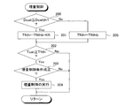
- This routine is a routine that is started every predetermined period.
- step 200 it is determined whether or not the catalyst use degree Dcat is less than or equal to the first degree Dcatth1 (Dcat ⁇ Dcatth1).
- Dcat ⁇ Dcatth1 the catalyst use degree Dcat is less than or equal to the first degree Dcatth1 (Dcat ⁇ Dcatth1).
- Dcat ⁇ Dcatth1 the catalyst use degree Dcat is less than or equal to the first degree Dcatth1
- step 201 a temperature that is higher than the reference temperature Tfitb of the execution permission temperature by a predetermined temperature Kfi is set as the execution permission temperature Tfith, and the routine proceeds to step 202.
- step 205 the reference temperature Tfitb of the execution permission temperature is set to the execution permission temperature Tfit, and the routine proceeds to step 202.
- Step 202 it is determined whether or not the catalyst temperature Tcat is equal to or higher than the execution permission temperature Tfit (Tcat ⁇ Tfit).
- Tcat ⁇ Tfit the routine proceeds to step 203.
- the routine ends.
- the routine proceeds from step 201 to step 202, the execution permission temperature Tfith set in step 201 is used in step 202, and when the routine proceeds from step 205 to step 202, step 202 includes step 205.
- the execution permission temperature Tfith set in is used.
- step 203 it is determined whether or not the increase control condition (that is, the specific condition described in the second embodiment) is satisfied. If it is determined that the increase control condition is satisfied, the routine proceeds to step 204 where the increase control is executed, and then the routine ends. On the other hand, when it is determined that the increase control condition is not satisfied, the routine ends.
- the increase control condition that is, the specific condition described in the second embodiment
- execution prohibition temperature is “execution prohibition temperature described in relation to the first embodiment”.
- the execution prohibition temperature is set to a temperature lower than the reference temperature while the catalyst use degree is equal to or less than a predetermined degree (hereinafter, this degree is referred to as “first degree”). While the degree of catalyst use is less than or equal to another predetermined degree (hereinafter referred to as “second degree”) that is greater than the first degree and greater than the first degree, A temperature higher than the reference temperature is set.
- first degree a predetermined degree
- second degree another predetermined degree
- the following effects can be obtained. That is, in the third embodiment, while the degree of catalyst use is greater than the first degree and less than or equal to the second degree, the execution prohibition temperature is set to a temperature higher than the reference temperature. According to this, since the opportunity for executing the fuel supply stop control increases, the aggregation of the complex oxide is promoted. For this reason, the effect that the precipitation rate of an active element can be reduced is acquired. In addition, when such an effect is acquired, for example, the active element solid solubility (that is, the ratio of the active element that is dissolved in the composite oxide among the active elements) is set as the target solid solubility (that is, the target active element).
- the active element solid solubility that is, the ratio of the active element that is dissolved in the composite oxide among the active elements
- the first degree in the third embodiment may be the same as or different from the first degree in the first embodiment. Further, in the third embodiment, after the degree of catalyst use becomes greater than the second degree, for example, the execution prohibition temperature is set to the reference temperature.
- the increase control of the second embodiment may be adopted.
- the catalyst use degree is equal to or lower than the first degree mentioned in the second embodiment
- the execution permission temperature is set to a temperature higher than the reference temperature.
- the first degree used for the increase control at this time may be the same as or different from the first degree used for the FC control of the third embodiment.
- This routine is a routine that is started every predetermined period.
- step 300 it is determined whether or not the catalyst usage degree Dcat is equal to or less than the first degree Dcatth1 (Dcat ⁇ Dcatth1).
- Dcat ⁇ Dcatth1 the catalyst usage degree Dcat is equal to or less than the first degree Dcatth1
- step 305 it is determined whether or not the catalyst usage degree Dcat is equal to or less than the second degree Dcatth2 (Dcat ⁇ Dcatth2). If it is determined that Dcat ⁇ Dcatth2, the routine proceeds to step 306. On the other hand, if it is determined that Dcat ⁇ Dcatth2, the routine proceeds to step 307.
- step 301 a temperature that is lower than the reference temperature Tfcthb of the execution prohibition temperature by a predetermined temperature Kfc1 is set as the execution prohibition temperature Tfcth, and the routine proceeds to step 302.
- step 306 a temperature that is higher by a predetermined temperature Kfc2 than the reference temperature Tfcthb of the execution prohibition temperature is set as the execution prohibition temperature Tfcth, and the routine proceeds to step 302.
- step 307 the execution prohibition temperature reference temperature Tfcthb is set to the execution prohibition temperature Tfcth, and the routine proceeds to step 302.
- the predetermined temperature Kfc2 may be the same value as the predetermined temperature Kfc1 or a different value.
- step 302 it is determined whether or not the catalyst temperature Tcat is equal to or higher than the execution prohibition temperature Tfcth (Tcat ⁇ Tfcth).
- Tcat ⁇ Tfcth the execution prohibition temperature Tfcth set at step 301 is used.
- step 306 the execution prohibition temperature Tfcth set in step 307 is used and the routine proceeds from step 307 to step 302, the execution prohibition temperature Tfcth set in step 307 is used in step 302.
- step 303 it is determined whether the FC control condition (that is, the specific condition described in the first embodiment) is satisfied.
- the routine proceeds to step 304, where FC control is executed, and then the routine ends.
- the routine ends.
- active element solid solubility means “a proportion of active elements that are dissolved in a composite oxide among active elements”.
- the execution prohibition temperature is set to a temperature lower than the reference temperature while the catalyst usage level is below a predetermined level (hereinafter, this level is referred to as “first level”). While the catalyst use degree is less than or equal to another predetermined degree (hereinafter referred to as “the third degree”) that is greater than the first degree and greater than the first degree, A temperature higher than the reference temperature is set. Then, after the degree of catalyst use becomes greater than the second degree, the catalyst inflow exhaust air-fuel ratio is controlled to be leaner than the stoichiometric air-fuel ratio so that the active element solid solubility is controlled to the target solid solubility. Alternatively, control for controlling the catalyst inflow exhaust air-fuel ratio to an air-fuel ratio richer than the stoichiometric air-fuel ratio (hereinafter, this air-fuel ratio control is referred to as “solid solubility control”) is executed.
- the catalyst temperature becomes equal to or higher than a predetermined solid solution temperature or reaches a predetermined precipitation temperature.
- the catalyst inflow exhaust air-fuel ratio may be temporarily leaner than the stoichiometric air-fuel ratio or richer than the stoichiometric air-fuel ratio.
- the catalyst inflow exhaust air-fuel ratio becomes leaner than the stoichiometric air-fuel ratio when the catalyst temperature is equal to or higher than the predetermined solid solution temperature, the internal atmosphere of the catalyst becomes an oxidizing atmosphere.
- the active element When the active element has a property of being dissolved in the composite oxide when the temperature is higher than the solid solution temperature and the internal atmosphere of the catalyst is an oxidizing atmosphere, the active element is dissolved in the composite oxide.
- the catalyst inflow exhaust air-fuel ratio becomes richer than the stoichiometric air-fuel ratio when the catalyst temperature is equal to or higher than the predetermined deposition temperature, the internal atmosphere of the catalyst becomes a reducing atmosphere.
- the active element has the property of precipitating from the composite oxide when the internal atmosphere of the catalyst is a reducing atmosphere, the active element is precipitated from the composite oxide.
- the amount of the precipitated active element changes due to the change in the catalyst temperature and the change in the catalyst inflow exhaust air-fuel ratio during engine operation, and consequently the catalyst purification capacity changes.
- the active element usage ie, the degree to which the active element is used to activate the components in the exhaust gas
- the active element may degrade, resulting in the active ability of the active element (ie, The ability of the active element to increase the oxidation reaction activity or the reduction reaction activity of the components in the exhaust gas may decrease.
- the catalyst purification capacity may decrease.
- the catalyst purification ability also changes due to the change in the active ability of the active element during engine operation.
- the internal combustion engine in order for the internal combustion engine to exhibit the desired performance, it is used for engine control so that the internal combustion engine can exhibit the expected performance in consideration of changes in the catalyst purification capacity during engine operation. It is necessary to construct a control logic that can be controlled and to perform engine control. However, since the change in the catalyst purification capacity during engine operation varies depending on the engine operation mode and the degree of catalyst use, it is very complicated to construct a control logic or perform engine control as described above. It can be said that. On the other hand, the control logic can be constructed relatively easily and engine control can be performed relatively easily if the change in the catalyst purification capacity is assumed regardless of the mode of engine operation and the degree of catalyst use. Can do.
- the active element solid solubility is controlled to the target solid solubility.
- the catalyst inflow exhaust air-fuel ratio is controlled to be an air-fuel ratio leaner than the stoichiometric air-fuel ratio, or the catalyst inflow exhaust air-fuel ratio is controlled to be richer than the stoichiometric air-fuel ratio.
- the catalyst inflow exhaust air-fuel ratio is controlled to an air-fuel ratio leaner than the stoichiometric air-fuel ratio
- the catalyst temperature is equal to or higher than the predetermined solid solution temperature
- the precipitated active element is dissolved in the composite oxide, and as a result
- the active element solid solubility increases.
- the catalyst inflow exhaust air-fuel ratio is controlled to an air-fuel ratio richer than the stoichiometric air-fuel ratio
- the internal atmosphere of the catalyst becomes a reducing atmosphere, so that the solid solution active element Precipitates from the composite oxide, and as a result, the solid solubility of the active element decreases.
- the active element solid solubility is controlled to the target solid solubility by appropriately controlling the inflow exhaust air-fuel ratio depending on whether the active element solid solubility is larger or smaller than the target solid solubility.
- the amount of the precipitated active element is kept constant, so that the catalyst purification capability during engine operation can be easily assumed.
- the control logic used for engine control can be constructed relatively easily after the degree of catalyst use becomes relatively large, and the degree of catalyst use becomes relatively large. Even after this, the engine control can be performed relatively easily and the catalyst can exhibit the desired purification ability.
- the first degree in the fourth embodiment may be the same degree as or different from the first degree in the first embodiment, and may be the same degree as the first degree in the second embodiment. May be of different degrees.
- the second degree in the fourth embodiment may be the same degree as the second degree in the second embodiment or a different degree. Further, in the fourth embodiment, after the degree of use of the catalyst becomes larger than the second degree, for example, the execution prohibition temperature is set to the reference temperature.
- the increase control of the second embodiment may be adopted.
- the catalyst use degree is equal to or lower than the first degree mentioned in the second embodiment
- the execution permission temperature is set to a temperature higher than the reference temperature.
- the first degree used for the increase control at this time may be the same as or different from the first degree used for the FC control of the fourth embodiment.
- the fuel injection amount is made smaller than the target fuel injection amount.
- the fuel injection amount may be made larger than the target fuel injection amount.
- the throttle valve opening is set larger than the target throttle valve opening.
- the throttle valve opening is set to the target throttle valve opening. (That is, the amount of intake air may be reduced).
- the catalyst inflow exhaust air-fuel ratio is made leaner than the stoichiometric air-fuel ratio.
- the catalyst inflow exhaust air-fuel ratio is controlled to be richer than the stoichiometric air-fuel ratio, and the active element solid solubility matches the target solid solubility. In this case, the catalyst inflow exhaust air-fuel ratio is controlled to the stoichiometric air-fuel ratio.
- the condition that the catalyst inflow exhaust air / fuel ratio is controlled to be an air / fuel ratio leaner than the stoichiometric air / fuel ratio is that the catalyst temperature is equal to or higher than a predetermined solid solution temperature. It is preferable to add. That is, in this case, when the active element solid solubility is smaller than the target solid solubility and the catalyst temperature is equal to or higher than the predetermined solid solution temperature, the catalyst inflow exhaust air-fuel ratio is controlled to a lean air-fuel ratio than the stoichiometric air-fuel ratio.
- the catalyst inflow exhaust air-fuel ratio is controlled to the stoichiometric air-fuel ratio.
- the catalyst temperature is equal to or higher than the predetermined precipitation temperature. It is preferable.
- the catalyst inflow exhaust air-fuel ratio is controlled to be richer than the stoichiometric air-fuel ratio
- the catalyst inflow exhaust air-fuel ratio is controlled to the stoichiometric air-fuel ratio
- the fuel injection amount when the method of reducing the fuel injection amount to be smaller than the target fuel injection amount in order to control the catalyst inflow exhaust air / fuel ratio to an air / fuel ratio leaner than the stoichiometric air / fuel ratio, the fuel injection amount is set to the target fuel injection amount.
- the air-fuel ratio of the air-fuel mixture that is, the air-fuel ratio of the air-fuel mixture formed in the combustion chamber
- the fuel injection amount is controlled from the target fuel injection amount in order to control the catalyst inflow exhaust air / fuel ratio to an air / fuel ratio leaner than the stoichiometric air / fuel ratio in the fourth embodiment.
- the fuel injection amount is preferably close to the target fuel injection amount.
- the fuel injection amount is set to the target fuel injection amount.
- the target fuel injection amount is set to control the catalyst inflow exhaust air / fuel ratio to an air / fuel ratio richer than the stoichiometric air / fuel ratio in the fourth embodiment.
- the fuel injection amount is preferably close to the target fuel injection amount.
- the catalyst inflow exhaust air-fuel ratio is controlled to be an air-fuel ratio leaner than the stoichiometric air-fuel ratio.
- the target active element solid solubility range as the active element solid solubility is set as the target solid solubility range, and the active element solid solubility is lower than the lower limit of the target solid solubility range. May be controlled to an air-fuel ratio leaner than the stoichiometric air-fuel ratio.
- the active element solid solubility is within the target solid solubility range, the catalyst inflow exhaust air-fuel ratio is controlled to the stoichiometric air-fuel ratio.
- the catalyst inflow exhaust air-fuel ratio is controlled to be richer than the stoichiometric air-fuel ratio.
- the target active element solid solubility range as the active element solid solubility is set as the target solid solubility range, and the active element solid solubility is higher than the upper limit of the target solid solubility range. May be controlled to a richer air-fuel ratio than the stoichiometric air-fuel ratio.
- the catalyst inflow exhaust air-fuel ratio is controlled to the stoichiometric air-fuel ratio.
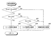
- FIG. 6 An example of a routine for executing the solid solubility control of the fourth embodiment will be described.
- This routine is a routine that is started every predetermined period.
- the routine shown in FIG. 6 can be adopted.
- step 400 it is determined whether or not the catalyst usage degree Dcat is larger than the second degree Dcatth2 (Dcat> Dcatth2).
- Dcat> Dcatth2 the routine proceeds to step 401.
- Dcat> Dcatth2 the routine proceeds to step 405.
- step 401 it is determined whether or not the active element solid solubility Ds is smaller than the target solid solubility Dst (Ds ⁇ Dst). If it is determined that Ds ⁇ Dst, the routine proceeds to step 402. On the other hand, when it is determined that Ds ⁇ Dst is not satisfied, the routine proceeds to step 403.
- step 403 it is determined whether or not the active element solid solubility Ds is larger than the target solid solubility Dst (Ds> Dst). If it is determined that Ds> Dst, the routine proceeds to step 404. On the other hand, when it is determined that Ds> Dst is not satisfied, the routine proceeds to step 405.
- step 402 the catalyst inflow exhaust air-fuel ratio is controlled to an air-fuel ratio that is leaner than the stoichiometric air-fuel ratio, and then the routine ends.
- step 404 the catalyst inflow exhaust air-fuel ratio is controlled to be richer than the stoichiometric air-fuel ratio, and then the routine ends.
- step 405 the catalyst inflow exhaust air-fuel ratio is controlled to the stoichiometric air-fuel ratio, and then the routine ends.
- this invention is internal combustion engines other than a spark ignition type internal combustion engine, for example,
- the present invention is also applicable to a compression self-ignition internal combustion engine (so-called diesel engine).
- the above-described embodiment is an embodiment in which the present invention is applied to a three-way catalyst, but the present invention is when the air-fuel ratio of the exhaust gas flowing in is leaner than the stoichiometric air-fuel ratio.
- the present invention can also be applied to a so-called NOx catalyst that can purify nitrogen oxide (NOx) in exhaust gas at a high purification rate.
- NOx nitrogen oxide
Landscapes
- Engineering & Computer Science (AREA)
- Chemical & Material Sciences (AREA)
- Combustion & Propulsion (AREA)
- Mechanical Engineering (AREA)
- General Engineering & Computer Science (AREA)
- Chemical Kinetics & Catalysis (AREA)
- Exhaust Gas After Treatment (AREA)
- Electrical Control Of Air Or Fuel Supplied To Internal-Combustion Engine (AREA)
- Combined Controls Of Internal Combustion Engines (AREA)
Abstract
Description
Qt=Qb×Kf …(2)
Claims (3)
- 排気ガス中の成分を浄化する触媒であって、排気ガス中の成分の酸化反応または還元反応を活性化する活性元素と該活性元素を担持する複合酸化物とを有する触媒を排気通路に備え、前記触媒の温度が予め定められた温度である所定固溶温度以上であり且つ前記触媒の内部雰囲気が酸化雰囲気であるときに前記活性元素が前記複合酸化物に固溶し、前記触媒の温度が予め定められた温度である所定析出温度以上であり且つ前記触媒の内部雰囲気が還元雰囲気であるときに前記活性元素が前記複合酸化物から析出する内燃機関の排気浄化装置において、
前記内燃機関が燃焼室への燃料の供給を停止する燃料供給停止制御を実行可能であって、前記触媒の温度が予め定められた温度である実行禁止温度以上であるときに前記燃料供給停止制御の実行が禁止されるとともに前記触媒の温度が前記実行禁止温度よりも低いときに前記燃料供給停止制御の実行が許可される場合において、前記触媒の使用度合が予め定められた度合以下である間は前記実行禁止温度がその基準温度よりも低い温度に設定され、
前記内燃機関が燃焼室への燃料の供給量を基準量よりも増量する燃料供給増量制御を実行可能であって、前記触媒の温度が予め定められた温度である実行許可温度以上であるときに前記燃料供給増量制御の実行が許可されるとともに前記触媒の温度が前記実行許可温度よりも低いときに前記燃料供給増量制御の実行が禁止される場合において、前記触媒の使用度合が予め定められた度合以下である間は前記実行許可温度がその基準温度よりも高い温度に設定される内燃機関の排気浄化装置。 - 請求項1に記載の内燃機関の排気浄化装置において、
前記内燃機関が前記燃料供給停止制御を実行可能である場合において、前記予め定められた度合を第1度合と称したとき、前記触媒の使用度合が前記第1度合よりも大きく且つ該第1度合よりも大きい予め定められた度合である第2度合以下である間は前記実行禁止温度がその基準温度よりも高い温度に設定される内燃機関の排気浄化装置。 - 請求項2に記載の内燃機関の排気浄化装置において、
前記内燃機関が前記燃料供給停止制御を実行可能である場合において、前記触媒の使用度合が前記第2度合よりも大きくなった後は前記活性元素のうち前記複合酸化物に固溶している活性元素の割合を表す活性元素固溶度が目標とする活性元素固溶度である目標固溶度に制御されるように前記触媒に流入する排気ガスの空燃比が理論空燃比よりもリーンな空燃比に制御し或いは前記触媒に流入する排気ガスの空燃比が理論空燃比よりもリッチな空燃比に制御する内燃機関の排気浄化装置。
Priority Applications (4)
| Application Number | Priority Date | Filing Date | Title |
|---|---|---|---|
| PCT/JP2011/078237 WO2013084307A1 (ja) | 2011-12-07 | 2011-12-07 | 内燃機関の排気浄化装置 |
| EP11877010.6A EP2789820A4 (en) | 2011-12-07 | 2011-12-07 | EXHAUST GAS CLEANING DEVICE FOR A COMBUSTION ENGINE |
| CN201180075354.7A CN103987933A (zh) | 2011-12-07 | 2011-12-07 | 内燃机的排气净化装置 |
| US14/362,444 US9097167B2 (en) | 2011-12-07 | 2011-12-07 | Exhaust gas purification device of internal combustion engine |
Applications Claiming Priority (1)
| Application Number | Priority Date | Filing Date | Title |
|---|---|---|---|
| PCT/JP2011/078237 WO2013084307A1 (ja) | 2011-12-07 | 2011-12-07 | 内燃機関の排気浄化装置 |
Publications (1)
| Publication Number | Publication Date |
|---|---|
| WO2013084307A1 true WO2013084307A1 (ja) | 2013-06-13 |
Family
ID=48573712
Family Applications (1)
| Application Number | Title | Priority Date | Filing Date |
|---|---|---|---|
| PCT/JP2011/078237 Ceased WO2013084307A1 (ja) | 2011-12-07 | 2011-12-07 | 内燃機関の排気浄化装置 |
Country Status (4)
| Country | Link |
|---|---|
| US (1) | US9097167B2 (ja) |
| EP (1) | EP2789820A4 (ja) |
| CN (1) | CN103987933A (ja) |
| WO (1) | WO2013084307A1 (ja) |
Cited By (2)
| Publication number | Priority date | Publication date | Assignee | Title |
|---|---|---|---|---|
| WO2015118856A1 (en) * | 2014-02-10 | 2015-08-13 | Toyota Jidosha Kabushiki Kaisha | Control device for internal combustion engine |
| US9458781B2 (en) | 2013-05-07 | 2016-10-04 | Toyota Jidosha Kabushiki Kaisha | Control device of internal combustion engine and method of controlling the same |
Families Citing this family (2)
| Publication number | Priority date | Publication date | Assignee | Title |
|---|---|---|---|---|
| JP6468255B2 (ja) * | 2016-07-04 | 2019-02-13 | トヨタ自動車株式会社 | 排気センサ |
| JP6593561B1 (ja) * | 2019-02-20 | 2019-10-23 | トヨタ自動車株式会社 | 内燃機関の触媒暖機処理監視装置、内燃機関の触媒暖機処理監視システム、データ解析装置、および内燃機関の制御装置 |
Citations (8)
| Publication number | Priority date | Publication date | Assignee | Title |
|---|---|---|---|---|
| JPH0368451A (ja) * | 1989-08-09 | 1991-03-25 | Toyota Motor Corp | 排気浄化用触媒の製造方法 |
| JP2005066559A (ja) | 2003-08-28 | 2005-03-17 | Mitsubishi Heavy Ind Ltd | 排ガス処理触媒および排ガス処理方法 |
| JP2006075748A (ja) * | 2004-09-10 | 2006-03-23 | Toyota Motor Corp | 排ガス浄化用触媒 |
| JP2006183624A (ja) | 2004-12-28 | 2006-07-13 | Mazda Motor Corp | エンジンの空燃比制御装置及び空燃比制御方法 |
| JP2008012480A (ja) | 2006-07-07 | 2008-01-24 | Cataler Corp | 排ガス浄化用触媒 |
| JP2008051063A (ja) | 2006-08-28 | 2008-03-06 | Toyota Motor Corp | 内燃機関の制御装置 |
| WO2008096575A1 (ja) | 2007-02-08 | 2008-08-14 | Daihatsu Motor Co., Ltd. | 触媒組成物 |
| JP2011098258A (ja) * | 2009-11-04 | 2011-05-19 | Toyota Motor Corp | 排ガス浄化用触媒およびその製造方法 |
Family Cites Families (15)
| Publication number | Priority date | Publication date | Assignee | Title |
|---|---|---|---|---|
| US5570575A (en) * | 1993-10-06 | 1996-11-05 | Nissan Motor Co., Ltd. | Fuel delivery control apparatus for use with internal combustion engine |
| JPH09248458A (ja) * | 1996-03-18 | 1997-09-22 | Toyota Central Res & Dev Lab Inc | 排ガス浄化用触媒及び排ガス浄化方法 |
| US6059057A (en) * | 1997-06-02 | 2000-05-09 | Toyota Jidosha Kabushiki Kaisha | Catalyst temperature control apparatus for hybrid vehicle |
| JP3739223B2 (ja) * | 1998-09-02 | 2006-01-25 | トヨタ自動車株式会社 | 排ガス浄化用触媒 |
| JP3575307B2 (ja) * | 1998-12-28 | 2004-10-13 | トヨタ自動車株式会社 | 排ガス浄化用触媒及びその製造方法 |
| WO2002062468A1 (fr) * | 2001-02-02 | 2002-08-15 | Hitachi, Ltd. | Catalyseur de traitement des gaz d'émission et moteur à combustion interne pourvu d'un tel catalyseur |
| US6892527B2 (en) * | 2002-07-16 | 2005-05-17 | Mitsubishi Jidosha Kogyo Kabushiki Kaisha | Catalyst deterioration suppressing apparatus and method |
| JP4192791B2 (ja) * | 2004-01-16 | 2008-12-10 | トヨタ自動車株式会社 | 排ガス浄化用触媒 |
| CN100479920C (zh) * | 2004-03-11 | 2009-04-22 | 卡塔勒公司 | 排气净化催化剂 |
| DE602005001030T2 (de) * | 2004-07-20 | 2008-01-03 | Toyota Jidosha Kabushiki Kaisha | Steuervorrichtung eines Verbrennungsmotors |
| JP4321485B2 (ja) * | 2005-04-12 | 2009-08-26 | トヨタ自動車株式会社 | 排ガス浄化装置およびその方法 |
| EP2335823B8 (en) * | 2008-08-27 | 2015-11-18 | Umicore Shokubai Japan Co., Ltd. | Exhaust gas purification catalyst and exhaust gas purification method using same |
| JP5692594B2 (ja) | 2011-05-16 | 2015-04-01 | トヨタ自動車株式会社 | 排ガス浄化用触媒 |
| JP5569653B2 (ja) * | 2011-08-30 | 2014-08-13 | トヨタ自動車株式会社 | 内燃機関の排気浄化装置 |
| JP5867450B2 (ja) * | 2013-05-07 | 2016-02-24 | トヨタ自動車株式会社 | 内燃機関の制御装置 |
-
2011
- 2011-12-07 EP EP11877010.6A patent/EP2789820A4/en not_active Withdrawn
- 2011-12-07 WO PCT/JP2011/078237 patent/WO2013084307A1/ja not_active Ceased
- 2011-12-07 US US14/362,444 patent/US9097167B2/en not_active Expired - Fee Related
- 2011-12-07 CN CN201180075354.7A patent/CN103987933A/zh active Pending
Patent Citations (8)
| Publication number | Priority date | Publication date | Assignee | Title |
|---|---|---|---|---|
| JPH0368451A (ja) * | 1989-08-09 | 1991-03-25 | Toyota Motor Corp | 排気浄化用触媒の製造方法 |
| JP2005066559A (ja) | 2003-08-28 | 2005-03-17 | Mitsubishi Heavy Ind Ltd | 排ガス処理触媒および排ガス処理方法 |
| JP2006075748A (ja) * | 2004-09-10 | 2006-03-23 | Toyota Motor Corp | 排ガス浄化用触媒 |
| JP2006183624A (ja) | 2004-12-28 | 2006-07-13 | Mazda Motor Corp | エンジンの空燃比制御装置及び空燃比制御方法 |
| JP2008012480A (ja) | 2006-07-07 | 2008-01-24 | Cataler Corp | 排ガス浄化用触媒 |
| JP2008051063A (ja) | 2006-08-28 | 2008-03-06 | Toyota Motor Corp | 内燃機関の制御装置 |
| WO2008096575A1 (ja) | 2007-02-08 | 2008-08-14 | Daihatsu Motor Co., Ltd. | 触媒組成物 |
| JP2011098258A (ja) * | 2009-11-04 | 2011-05-19 | Toyota Motor Corp | 排ガス浄化用触媒およびその製造方法 |
Non-Patent Citations (1)
| Title |
|---|
| See also references of EP2789820A4 |
Cited By (2)
| Publication number | Priority date | Publication date | Assignee | Title |
|---|---|---|---|---|
| US9458781B2 (en) | 2013-05-07 | 2016-10-04 | Toyota Jidosha Kabushiki Kaisha | Control device of internal combustion engine and method of controlling the same |
| WO2015118856A1 (en) * | 2014-02-10 | 2015-08-13 | Toyota Jidosha Kabushiki Kaisha | Control device for internal combustion engine |
Also Published As
| Publication number | Publication date |
|---|---|
| US9097167B2 (en) | 2015-08-04 |
| EP2789820A1 (en) | 2014-10-15 |
| US20140331652A1 (en) | 2014-11-13 |
| CN103987933A (zh) | 2014-08-13 |
| EP2789820A4 (en) | 2015-08-26 |
Similar Documents
| Publication | Publication Date | Title |
|---|---|---|
| JP3684934B2 (ja) | 内燃機関の排気浄化装置 | |
| US10072545B2 (en) | Exhaust purification system of internal combustion engine | |
| JP5278454B2 (ja) | 多気筒内燃機関の気筒間空燃比ばらつき異常検出装置 | |
| JP5569653B2 (ja) | 内燃機関の排気浄化装置 | |
| JP5664884B2 (ja) | 内燃機関の空燃比制御装置 | |
| CN106089461A (zh) | 内燃机 | |
| US8997458B2 (en) | Air/fuel ratio control device for internal-combustion engine | |
| WO2013084307A1 (ja) | 内燃機関の排気浄化装置 | |
| CN106460692B (zh) | 内燃机的控制系统 | |
| US10378466B2 (en) | Control system of internal combustion engine | |
| US10087864B2 (en) | Control device of internal combustion engine | |
| JPWO2013084307A1 (ja) | 内燃機関の排気浄化装置 | |
| JP7605147B2 (ja) | 内燃機関の排気浄化装置 | |
| US10781765B2 (en) | Control system of internal combustion engine | |
| JP2019065797A (ja) | 内燃機関の排気浄化装置 | |
| JP2013096336A (ja) | 内燃機関の制御装置 | |
| JP2007071090A (ja) | 内燃機関の制御装置 | |
| JP2004346862A (ja) | 内燃機関 | |
| JP2001050084A (ja) | 排気浄化装置 |
Legal Events
| Date | Code | Title | Description |
|---|---|---|---|
| 121 | Ep: the epo has been informed by wipo that ep was designated in this application |
Ref document number: 11877010 Country of ref document: EP Kind code of ref document: A1 |
|
| ENP | Entry into the national phase |
Ref document number: 2013547995 Country of ref document: JP Kind code of ref document: A |
|
| WWE | Wipo information: entry into national phase |
Ref document number: 14362444 Country of ref document: US Ref document number: 2011877010 Country of ref document: EP |
|
| NENP | Non-entry into the national phase |
Ref country code: DE |