WO2013088491A1 - 列車情報管理装置および列車情報管理方法 - Google Patents
列車情報管理装置および列車情報管理方法 Download PDFInfo
- Publication number
- WO2013088491A1 WO2013088491A1 PCT/JP2011/078678 JP2011078678W WO2013088491A1 WO 2013088491 A1 WO2013088491 A1 WO 2013088491A1 JP 2011078678 W JP2011078678 W JP 2011078678W WO 2013088491 A1 WO2013088491 A1 WO 2013088491A1
- Authority
- WO
- WIPO (PCT)
- Prior art keywords
- packet
- information
- control information
- train control
- train
- Prior art date
- Legal status (The legal status is an assumption and is not a legal conclusion. Google has not performed a legal analysis and makes no representation as to the accuracy of the status listed.)
- Ceased
Links
Images



Classifications
-
- H—ELECTRICITY
- H04—ELECTRIC COMMUNICATION TECHNIQUE
- H04L—TRANSMISSION OF DIGITAL INFORMATION, e.g. TELEGRAPHIC COMMUNICATION
- H04L47/00—Traffic control in data switching networks
- H04L47/10—Flow control; Congestion control
- H04L47/34—Flow control; Congestion control ensuring sequence integrity, e.g. using sequence numbers
-
- B—PERFORMING OPERATIONS; TRANSPORTING
- B61—RAILWAYS
- B61L—GUIDING RAILWAY TRAFFIC; ENSURING THE SAFETY OF RAILWAY TRAFFIC
- B61L15/00—Indicators provided on the vehicle or train for signalling purposes
- B61L15/0018—Communication with or on the vehicle or train
- B61L15/0036—Conductor-based, e.g. using CAN-Bus, train-line or optical fibres
-
- B—PERFORMING OPERATIONS; TRANSPORTING
- B61—RAILWAYS
- B61L—GUIDING RAILWAY TRAFFIC; ENSURING THE SAFETY OF RAILWAY TRAFFIC
- B61L25/00—Recording or indicating positions or identities of vehicles or trains or setting of track apparatus
- B61L25/02—Indicating or recording positions or identities of vehicles or trains
- B61L25/028—Determination of vehicle position and orientation within a train consist, e.g. serialisation
-
- B—PERFORMING OPERATIONS; TRANSPORTING
- B61—RAILWAYS
- B61L—GUIDING RAILWAY TRAFFIC; ENSURING THE SAFETY OF RAILWAY TRAFFIC
- B61L99/00—Subject matter not provided for in other groups of this subclass
Definitions
- the present invention relates to a train information management device and a train information management method.
- equipment such as a brake and an air conditioner and individually controls the operation of each equipment.
- This train information management device is composed of, for example, a central device and a terminal device.
- equipment operation state information is collected, and the collected operation state information is transmitted from the terminal device to the central device.
- management and control of devices are performed based on collected operation state information.
- the central device is connected to a control operation device such as a master controller (master controller), performs arithmetic processing based on notch information and the like input from the control operation device, and is a control command signal for controlling the entire train.
- a control operation device such as a master controller (master controller)
- the terminal device transmits the train control information received from the central device to each device, and each device operates according to the data (device data) related to the device in the train control information.
- the efficient operation of the train is realized by transmitting the device data from the central device to each device. Therefore, increasing the reliability of the transmission system including the train information management device is an important issue from the viewpoint of realizing comfortable and efficient operation of the train.
- the secondary (second system) central device is triggered by the fact that the central device is duplicated and transmission from the primary (first system) central device is interrupted. Is configured to start transmitting train control information.
- Patent Document 1 has a problem that switching from the 1-system central device to the 2-system central device cannot be performed instantaneously.
- the system 1 central unit which is a regular master station and the system 2 central unit which is a backup master station are connected to the transmission line and the system 1 central device is not out of order
- Data transmission is performed on the transmission line from the system 1 central device.
- the data transmission is interrupted due to the failure of the system 1 central device, data transmission is performed on the transmission line from the system 2 central device that detects the failure.
- the present invention has been made in view of the above, and an object of the present invention is to obtain a train information management device and a train information management method capable of transmitting train control information without increasing traffic on a duplex trunk transmission line. To do.
- the present invention provides a first backbone transmission line disposed across a plurality of vehicles constituting a train formation and a plurality of trains constituting a train formation.
- a control command signal for a receiver mounted on the vehicle based on control input information that is connected to a second trunk transmission line that is disposed over the vehicle and forms a redundant system of the first trunk transmission line.
- the first train control information generation unit that generates the first train control information as the first train control information, and the first train control information that is given to the first train control information each time the first train control information is generated
- a first packet generator that alternately sends the first packet to the first trunk transmission path and the second trunk transmission path for each predetermined period.
- a first information sending unit; and the first base The control input information starting from the time when a predetermined period is multiplied by 1/2 from the time when the first train control information is sent and connected to the transmission line and the second backbone transmission line
- a second train control information generating unit that generates second train control information that is the same or different from the first train control information based on the first train control information, and each time the second train control information is generated
- a second packet having a sequence number assigned to the second train control information is generated, and the second packet is opposite to the backbone transmission path from which the first packet was sent at each predetermined period.
- a second information transmission unit including a second packet generation unit to be transmitted to the main transmission line on the side.
- the train control information packet with the sequence number alternately assigned is sent from the two train information central units to the duplexed trunk transmission line, the traffic on the duplexed trunk transmission line is increased. There is an effect that it is possible to transmit the train control information without making it.
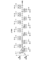
- FIG. 1 is a diagram schematically illustrating a train information management apparatus according to the first embodiment of the present invention.
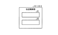
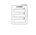
- FIG. 2 is a diagram showing the configuration of the 1-system transmission control unit and the 2-system transmission control unit shown in FIG.
- FIG. 3 is a diagram schematically illustrating a packet transmitted from the central apparatus to the basic transmission path.
- FIG. 4 is a diagram for explaining the operation of the train information management apparatus according to the first embodiment of the present invention.
- FIG. 5 is a diagram for explaining a packet transmitted when an abnormality occurs in the system 1 central apparatus.
- FIG. 6 is a diagram for explaining a packet transmitted when an abnormality occurs in the 1-system trunk transmission line.
- FIG. 7 is a diagram for explaining the operation of the train information management apparatus according to the second embodiment of the present invention.
- FIG. 1 is a diagram schematically illustrating a train information management apparatus according to the first embodiment of the present invention.
- FIG. 2 is a diagram showing the configuration of the 1-system transmission control unit and the 2-system transmission control unit shown in
- FIG. 8 is a diagram for explaining a packet transmitted when an abnormality occurs in the first-system central apparatus according to the second embodiment.
- FIG. 9 is a diagram for explaining a packet transmitted when an abnormality occurs in the first-system trunk transmission line according to the second embodiment.
- FIG. 10 is a diagram illustrating another configuration row of the 1-system transmission control unit and the 2-system transmission control unit.
- FIG. 1 is a diagram schematically showing a train information management apparatus according to a first embodiment of the present invention.
- FIG. 1 shows a first-system trunk transmission line (first trunk transmission line) that is a main trunk transmission line. (Transmission path) 40-1 and a secondary trunk transmission path (second trunk transmission path) 40-2 which is a secondary trunk transmission path.
- the 1-system trunk transmission line 40-1 and the 2-system trunk transmission line 40-2 constitute a trunk network, and are LAN (local area network) trunk lines using, for example, Ethernet (registered trademark).
- the number of vehicles is not limited to the illustrated example.
- the first vehicle includes a first-system central device 11-1 that is a main central device that constitutes a train information management device, and a second-system central device 11-2 that is a subordinate central device that constitutes a train information management device. Is installed.
- the system 1 central device 11-1 and the system 2 central device 11-2 are connected to the system 1 backbone transmission line 40-1 and the system 2 backbone transmission line 40-2 via the hub 22-1 and the hub 22-2, respectively.
- the 1-system central device 11-1 has a 1-system transmission control unit 12-1, and the 2-system central device 11-2 has a 2-system transmission control unit 12-2. Details of the 1-system transmission control unit 12-1 and the 2-system transmission control unit 12-2 will be described later.
- Vehicles other than the leading vehicle are equipped with a terminal device 16-1 and a terminal device 16-2 that constitute a train information management device.
- the terminal devices 16-1 and 16-2 include a hub 23-1 and a hub 23-2. Are connected to the 1-system trunk transmission line 40-1 and the 2-system trunk transmission line 40-2, respectively.
- two systems such as the second system central device 11-2 and the terminal device 16-2 are one redundant system such as the first system central device 11-1 and the terminal device 16-1.
- the same operation is performed under the same configuration.
- information from devices such as VVVF, SIV, brakes, air conditioners, etc. is sent to the 1-system trunk transmission path 40-1 and the 2-system trunk transmission path.
- 40-2 is increased in redundancy and higher reliability can be obtained.
- the train information management device manages various types of train information such as train operation information, train position information, power running commands, brake commands, door opening / closing commands, etc. To do.
- the 1-system central device 11-1, the 2-system central device 11-2, the terminal device 16-1, and the terminal device 16-2 operate in cooperation with each other, collect information on the devices connected thereto, This information is shared via the 1-system trunk transmission line 40-1 and the 2-system trunk transmission line 40-2.
- FIG. 2 is a diagram showing the configuration of the 1-system transmission control unit 12-1 and the 2-system transmission control unit 12-2 shown in FIG.
- the 1-system transmission control unit 12-1 and the 2-system transmission control unit 12-2 have a train control information generation unit 51 and a packet generation unit 52, respectively, as main components.
- the train control information generation unit (first train control information generation unit) 51 in the 1-system transmission control unit 12-1 is based on the control input information described above, and each device and each terminal device 16-1, 16-2. 1st train control information which is a control command signal to is generated.
- the packet generation unit (first packet generation unit) 52 in the 1-system transmission control unit 12-1 performs a sequence to the first train control information.
- a first packet A1 to which a number is assigned is generated. This sequence number is a cyclic number for uniquely identifying the first train control information. Then, the first packet A1 is sent out to, for example, the 1-system trunk transmission line 40-1.
- the packet generation unit 52 in the 1-system transmission control unit 12-1 sets 1 to the previous sequence number in the first train control information.
- a first packet A2 is generated by giving the added number.
- the first packet A2 is sent to the opposite side (for example, the second-system backbone transmission line 40-2) from the backbone transmission line from which the first packet A1 was sent.
- the packet generation unit 52 in the 1-system transmission control unit 12-1 increments the sequence number by 1 each time the first train control information is generated, and the sequence number is set to the first train control. Packets added to the information are generated as first packets A1 and A2 and transmitted to the first-system trunk transmission line 40-1 or the second-system trunk transmission path 40-2.
- the packet generation unit 52 in the 1-system transmission control unit 12-1 generates the first packet A1 to which a number obtained by adding 1 to the previous sequence number is assigned.
- A2 are generated, and the generated first packets A1 and A2 are sent to the main transmission path opposite to the main transmission path from which the first packets A1 and A2 were sent last time.
- the period from when the first packet A1 is sent to when the first packet A2 is sent and the period from when the first packet A2 is sent to when the first packet A1 is sent are: , A predetermined cycle T1.
- the train control information generation unit (second train control information generation unit) 51 in the second-system transmission control unit 12-2 performs a period of 1 ⁇ 2 of the period T1 from the time when the first packet A1 is transmitted.
- the second train control information which is the same information as the first train control information, is generated based on the control input information.
- the packet generation unit (second packet generation unit) 52 in the second-system transmission control unit 12-2 performs a sequence to the second train control information.
- a second packet B2 to which a number is assigned is generated. This second packet B2 is sent out to, for example, the second-system trunk transmission line 40-2.
- the previous sequence number is set to 1 in the second train control information.
- the added number is assigned to generate the second packet B1.
- the second packet B1 is sent out to the main transmission line (for example, the 1-system main transmission line 40-1) opposite to the main transmission line from which the second packet B2 was sent out.
- the packet generation unit 52 in the second-system transmission control unit 12-2 increments the sequence number by one every time the second train control information is generated, and the second train control Packets added to the information are generated as second packets B1 and B2 and transmitted to the first-system trunk transmission line 40-1 or the second-system trunk transmission path 40-2.
- the packet generator 52 in the second transmission control unit 12-2 generates the second packet B1 to which a number obtained by adding 1 to the previous sequence number is added.
- B2 are generated, and the second packets B1 and B2 are sent to the main transmission path opposite to the main transmission path from which the second packets B1 and B2 were sent last time. Note that the period from when the second packet B2 is transmitted until the second packet B1 is transmitted and the period from when the second packet B1 is transmitted until the second packet B2 is transmitted. , A predetermined period T2.
- Control input information (for example, notch information of the master controller) is transmitted to the 1-system central apparatus 11-1 and the 2-system central apparatus 11-2.
- the system 1 transmission control unit 12-1 generates first train control information based on the control input information
- the system 2 transmission control unit 12-2 similarly controls the second train control information based on the control input information.
- Information is generated.
- the first train control information and the second train control information are information relating to, for example, the distribution of the brake force to the brake control device and the distribution of the power running torque to the VVVF inverter.
- a sequence number is assigned to each of the first train control information and the second train control information, and the packet to which the sequence number is assigned passes through the 1-system trunk transmission line 40-1 and the 2-system trunk transmission line 40-2. Are transmitted to the terminal device 16-1 and the terminal device 16-2. These packets are transmitted to a device (not shown) via the transmission path 40-1 and the transmission path 40-2.
- the terminal devices 16-1 and 16-2 that have received the packet transmit, for example, the train control information in the packet to each device (not shown).
- the terminal devices 16-1 and 16-2 collect operation state information data output from each device (not shown), and periodically store these data in the 1-system central device 11-1 and the 2-system central device. Transmit to the device 11-2 or the like.
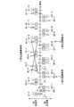
- FIG. 3 is a diagram schematically showing a packet sent from the central apparatus to the basic transmission line.
- FIG. 3 shows the 1-system central apparatus 11-1 and the 2-system central apparatus 11-2 shown in FIG. 1, and the first packets A1, A2 from the 1-system central apparatus 11-1 are transmitted. 2 and a path through which the second packets B1 and B2 from the second system central apparatus 11-2 are transmitted.
- These routes include, for example, a hub 23-1, a hub 23-2, a 1-system trunk transmission line 40-1, a 2-system trunk transmission path 40-2, a hub 23-1, and a hub 23-2. .
- the first packet A1 from the first-system central apparatus 11-1 is transmitted to the first-system trunk transmission line 40-1, and the second packet B1 from the second-system central apparatus 11-2 is transmitted.
- the first packet A2 from the first system central apparatus 11-1 is transmitted to the second system trunk transmission line 40-2, and the second packet B2 from the second system central apparatus 11-2 is transmitted.
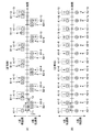
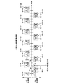
- FIG. 4 is a diagram for explaining the operation of the train information management apparatus according to the first embodiment of the present invention.
- FIG. 4A shows first packets A1 and A2 and second packets B1 and B2 generated by the train information management apparatus according to the first embodiment.
- the upper side of FIG. 4A shows the first packet A1 and the second packet B1 transmitted to the system 1 trunk transmission line 40-1
- the lower side of FIG. A second packet B2 and a first packet A2 transmitted to the second-system trunk transmission line 40-2 are shown.
- the first system central device 11-1 generates a first packet A1-1 in which the sequence number “1” is added to the first train control information “1” generated at a predetermined time, and this first packet A1-1 is sent to, for example, the 1-system trunk transmission line 40-1.
- the second train control information "2" when the time obtained by multiplying the period T1 by 1/2 has elapsed from the time when the first packet A1-1 was transmitted, the second train control information "2" And the second packet B2-1 is generated in which the same sequence number “1” as the sequence number of the first packet A1-1 is added to the second train control information “2”.
- the second train control information “2” has the same contents as the first train control information of the first packet A1-1.
- the second packet B2-1 is sent out to the main transmission line (second-system main transmission line 40-2) on the opposite side to the main transmission line from which the first packet A1-1 was sent out.
- the first-system central unit 11-1 generates the first train control information “2” after the elapse of the cycle T1 from the time when the first packet A1-1 is generated, and the first train A first packet A2-2 is generated by adding the sequence number “2” obtained by adding 1 to the sequence number “1” of the first packet A1-1 to the control information “2”.
- the first train control information “2” is newly generated based on the control input information.
- the first packet A2-2 is sent to the main transmission line (system 2 main transmission line 40-2) opposite to the main transmission line from which the first packet A1-1 was sent before the period T1. Is done.
- the second system central device 11-2 generates the second train control information “1” after the elapse of the period T2 from the time when the second packet B2-1 is generated, and the second train A second packet B1-2 is generated by adding a sequence number “2” obtained by adding 1 to the sequence number of the second packet B2-1 to the control information “1”.
- the second train control information “1” has the same contents as the first train control information of the first packet A2-2.
- the second packet B1-2 is sent to the main transmission line (for example, the 1-system main transmission line 40-1) opposite to the main transmission line of the second packet B2-1 sent before the period T2. Sent out.
- the 1st central apparatus 11-1 and 2nd central apparatus 11-2 generate the first packet (A1-3 to A1-13) and the second packet (B2-3 to B1-12). Then, these packets are sent out to the 1-system trunk transmission line 40-1 and the 2-system trunk transmission line 40-2.
- the terminal device 16-1 receives a packet surrounded by a dotted frame and transmits train control information in the packet to each device (not shown). More specifically, the terminal device 16-1 performs a process of adopting the first received packet when the same sequence number is assigned when each transmitted packet is received. For example, when the terminal device 16-1 receives the first packet A2-2 and the second packet B1-2 with the same sequence number, the first packet A2-2 that arrives first is adopted, The second packet B1-2 that has arrived second is discarded.
- FIG. 4B shows the first packets A1-1 to A1-13 transmitted to the 1-system trunk transmission line and the 2-system trunk transmission line by the conventional technique represented by Patent Document 1. .
- the upper side of FIG. 4B shows the first packets A1-1 to A1-13 transmitted to the system 1 backbone transmission line 40-1, and the lower side of FIG. Shown are first packets A2-1 to A2-13 transmitted to the trunk transmission line 40-2.
- the 1-system central apparatus 11-1 as the master station is used regularly, and the 2-system central apparatus 11-2 is treated as a spare. Therefore, when the 1-system central apparatus 11-1 is not out of order, the 1-system trunk transmission line 40-1 and the 2-system trunk transmission line 40-2 have the first system Only packets A1 and A2 are transmitted.
- the receiving apparatus side transmits the first packet A1, which is transmitted via the 1-system trunk transmission path 40-1, Of A2, only the first packet A1 is adopted.
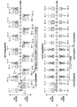
- FIG. 5 is a diagram for explaining a packet transmitted when an abnormality occurs in the system 1 central unit.
- FIG. 5A shows the first packets A1, A2 and second packets sent from the train information management apparatus according to the first embodiment to the first-system trunk transmission path 40-1 and the second-system trunk transmission path 40-2. Packets B1 and B2 are shown. However, FIG. 5A shows that, for example, immediately after the second packet B1-2 is sent out (time t1), a certain abnormality has occurred in the first-system central apparatus 11-1, so that the first-system trunk transmission line 40 A state in which the first packets A1 and A2 are not transmitted to the -1 and 2 system trunk transmission lines 40-2 is shown.
- the first packet (A1-3, A2-4, etc.) after the second packet B1-2 is not transmitted, but the second packet (B2-3, B1-4, etc.) is not transmitted. ) Is continuously transmitted.
- the terminal device 16-1 receives a packet surrounded by a dotted frame, and transmits train control information in the packet to each device (not shown).
- the second packet (B2-3, B1-4, B2-5, etc.) after the first packet A2-2 is employed.
- the second packet B2-3 is transmitted when a time obtained by multiplying the period T1 by 3/2 has elapsed since the time when the first packet A2-2 was transmitted. Then, a packet that arrives at such a time exceeding the period T1 is also adopted.
- FIG. 5B shows the first packets A1 and A2 transmitted by the above-described conventional method.
- an abnormality occurs in the 1-system central apparatus 11-1 immediately after the first packet A1-2 and the first packet A2-2 are transmitted, so that the 1-system backbone A state in which the first packet A1-3 and the packets after the first packet A2-3 are not sent to the transmission line 40-1 and the second-system trunk transmission line 40-2 is shown.
- the second-system central apparatus 11-2 cannot receive data from the first-system central apparatus 11-1 (time t1) and a certain time elapses (time t2) ) Starts transmission of packets from the second system central apparatus 11-2 (in the example of FIG.
- the train information management apparatus since the train information management apparatus according to the first embodiment alternately sends packets with sequence numbers to the duplexed trunk transmission line, the time lag as described above does not occur, and mutual In addition, a transmission line or the like for monitoring the soundness is unnecessary, and traffic is not increased.
- FIG. 6 is a diagram for explaining a packet transmitted when an abnormality occurs in the 1-system trunk transmission line.
- FIG. 6 shows the first packets A1, A2 and the second packet B1 sent from the train information management apparatus according to the first embodiment to the first-system trunk transmission path 40-1 and the second-system trunk transmission path 40-2.
- B2 is indicated and, for example, the first packet A1-3 is transmitted (time t1) immediately after (time t1), an abnormality occurs in the 1-system trunk transmission line 40-1, for example, the second packet B1-4
- the state where the first packet A1-5 and the like cannot be transmitted is shown.
- a packet (such as the second packet B1-4) to be transmitted to the first-system trunk transmission line 40-1 is not transmitted, but the second-system trunk transmission path 40- 2 can be transmitted continuously.
- the terminal device 16-1 receives a packet surrounded by a dotted frame, and transmits train control information in the packet to each device (not shown).
- the second packet B2-5, the first packet A2-6, the second packet B2-7, and the first packet A2-8 are employed after the first packet A2-4.
- the terminal device 16-1 employs the first packets A1-9, A2-10, and the like. Since the second packet B2-9 transmitted after restoration is assigned the same number as the sequence number of the first packet A1-9, the second packet B2-9 is discarded.
- the second packet B2-5 is generated when a time period obtained by multiplying the period T1 by 3/2 has elapsed since the time when the first packet A2-4 was transmitted. Then, a packet that arrives at such a time exceeding the period T1 is also adopted.
- control input information input to the 1-system central device 11-1 and the 2-system central device 11-2 includes, for example, operation control information of the electromagnetic valve of the brake control device, It may be information about the route on which the train operates.
- the train information management apparatus configures a train formation with the 1-system trunk transmission line 40-1 disposed over a plurality of vehicles that form the train formation.
- a device mounted on a vehicle based on control input information including notch information, which is connected to a second-system trunk transmission line 40-2 that is arranged over a plurality of vehicles and forms a redundant system of the first-system trunk transmission line 40-1.
- a first train control information generating unit (train control information generating unit 51 in the 1-system transmission control unit 12-1) that generates first train control information as a control command signal for the first train control information Each time it is generated, the first packets A1 and A2 with the sequence numbers assigned to the first train control information are generated, and the first packets A1 and A2 are sent to the 1-system trunk transmission line 40- at every predetermined period T1.
- system transmission line 40-2 1-system central apparatus 11-1 having a first packet generation section (packet generation section 52 in 1-system transmission control section 12-1) and 1-system trunk transmission lines 40-1 and 2 Based on the control input information, starting from the time when the predetermined period T1 is multiplied by 1/2 from the time when the first train control information is sent and connected to the main trunk transmission line 40-2.
- a second train control information generation unit (train control information generation unit 51 in the second transmission control unit 12-2) that generates second train control information that is the same train control information as the first train control information; Each time the second train control information is generated, the second packets B1 and B2 with the sequence numbers assigned to the second train control information are generated, and the second packets B1 and B2 are generated at every predetermined period T2.
- a backbone transmission path (for example, a 1-system base) from which one packet A1, A2 is sent
- a second packet generation unit (packet generation unit 52 in the second transmission control unit 12-2) to be sent to the main transmission line (for example, the second transmission system transmission line 40-2) opposite to the transmission line 40-1) Therefore, there is a time lag when the main body of data transmission is switched from the 1-system central device to the 2-system central device as in the prior art.
- Embodiment 2 Although the train information management device according to the first embodiment is configured such that the sequence number is incremented every cycle T1, the train information management device according to the second embodiment needs to increase the control frequency of the equipment. When certain control input information (for example, notch information from the master controller, operation control information of the solenoid valve of the brake control device, etc.) is input, the sequence number is incremented every half time of the period T1. It is configured.
- the train information management device according to the second embodiment has the same configuration as the components shown in FIG. 1 and FIG. 2, and is the same as the train information management device according to the first embodiment in the same parts. The description will be omitted with reference numerals, and only different parts will be described here.
- the train control information generation unit 51 in the 1-system central device 11-1 generates first train control information based on the control input information.
- the packet generation unit 52 in the first-system transmission control unit 12-1 when the first first train control information is generated, the packet generation unit 52 in the first-system transmission control unit 12-1 generates a first packet in which a sequence number is assigned to the first train control information. A1 is generated. The first packet A1 is sent out to, for example, the 1-system trunk transmission line 40-1.
- the packet generation unit 52 in the 1-system transmission control unit 12-1 sets the previous sequence number to 2 in the first train control information.
- a first packet A2 is generated by giving the added number.
- the first packet A2 is sent to the opposite side (for example, the second-system backbone transmission line 40-2) from the backbone transmission line from which the first packet A1 was sent.
- the packet generation unit 52 in the 1-system transmission control unit 12-1 generates the first packet A1 to which a number obtained by adding 2 to the previous sequence number is added.
- A2 are generated, and the first packets A1 and A2 are sent to the main transmission line on the opposite side of the main transmission line from which the first packets A1 and A2 were sent last time.
- the train control information generation unit 51 in the second-system transmission control unit 12-2 starts the control input starting from the time when 1 ⁇ 2 of the period T1 has elapsed from the time when the first packet A1 is transmitted. Based on the information, second train control information that is different from the first train control information is generated.
- the packet generation unit 52 in the second-system transmission control unit 12-2 when the first second train control information is generated, the packet generation unit 52 in the second-system transmission control unit 12-2 generates a second packet in which a sequence number is assigned to the second train control information. B2 is generated. This second packet B2 is sent out to, for example, the second-system trunk transmission line 40-2.
- the second train control information is generated for the second train control unit 52 in the 2 system transmission control unit 12-2, 2 is added to the previous sequence number in the second train control information.
- the added number is assigned to generate the second packet B1.
- the second packet B1 is sent out to the main transmission line (for example, the 1-system main transmission line 40-1) opposite to the main transmission line from which the second packet B2 was sent out.
- the packet generation unit 52 in the second transmission control unit 12-2 generates the second packet B1 to which a number obtained by adding 2 to the previous sequence number is added. , B2 are generated, and the second packets B1 and B2 are sent to the main transmission path opposite to the main transmission path from which the second packets B1 and B2 were sent last time.
- FIG. 7 is a diagram for explaining the operation of the train information management apparatus according to the second embodiment of the present invention.
- FIG. 7 shows a packet transmitted when the central apparatus and the main transmission path are normal.
- the upper side of FIG. 7 shows the first packet A1 and the second packet B1 transmitted to the system 1 backbone transmission line 40-1, and the lower side of FIG. 7 shows the system 2 backbone transmission line 40-2.
- the second packet B2 and the first packet A2 to be transmitted are shown.
- the first system central device 11-1 generates a first packet A1-1 in which the sequence number “1” is added to the first train control information “1” generated at a predetermined time, and this first packet A1-1 is sent to, for example, the 1-system trunk transmission line 40-1.
- the second train control information "2" is generated, and the second packet B2-2 is generated by adding the sequence number “2” obtained by adding 1 to the sequence number of the first packet A1-1 to the second train control information “2”. Is done.
- the second train control information “2” is different from the first train control information of the first packet A1-1.
- the second packet B2-2 is sent out to the main transmission line (second-system main transmission line 40-2) on the opposite side to the main transmission line from which the first packet A1-1 was sent out.
- the first-system central unit 11-1 generates the first train control information “2” after the elapse of the cycle T1 from the time when the first packet A1-1 is generated, and the first train A first packet A2-3 is generated by adding a sequence number “3” obtained by adding 2 to the sequence number “1” of the first packet A1-1 to the control information “2”.
- the first train control information “2” is newly generated based on the control input information.
- the first packet A2-3 is sent to the main transmission line (system 2 main transmission line 40-2) opposite to the main transmission line from which the first packet A1-1 was sent before the period T1. Is done.
- the second system central device 11-2 generates the second train control information “1” after the elapse of the cycle T2 from the time when the second packet B2-2 is generated, and this second train A second packet B1-4 in which a sequence number “4” obtained by adding 2 to the sequence number of the second packet B2-2 is added to the control information “1” is generated.
- the second train control information “1” is different from the first train control information of the first packet A2-3.
- the second packet B1-4 is sent to the main transmission line (for example, the 1-system main transmission line 40-1) opposite to the main transmission line of the second packet B2-2 sent before the period T2. Sent out.
- first-system central apparatus 11-1 and second-system central apparatus 11-2 generate first packets (A1-5 to A1-25) and second packets (B2-6 to B1-24). Then, these packets are sent out to the 1-system trunk transmission line 40-1 and the 2-system trunk transmission line 40-2.
- the terminal device 16-1 receives the first packet and the second packet surrounded by a dotted frame, and transmits train control information in the packet to each device (not shown).
- FIG. 8 is a diagram for explaining a packet transmitted when an abnormality occurs in the first-system central apparatus according to the second embodiment.
- FIG. 8 shows the first packets A1, A2 and the second packet B1 sent from the train information management apparatus according to the second embodiment to the first-system trunk transmission path 40-1 and the second-system trunk transmission path 40-2.
- B2 is indicated, and for example, immediately after the second packet B1-4 is transmitted (time t1), the occurrence of any abnormality in the 1-system central apparatus 11-1 causes the 1-system trunk transmission line 40-1 and A state in which the first packets A1 and A2 are not transmitted to the second-system trunk transmission line 40-2 is shown.
- the first packet (A1-5, A2-7, etc.) after time t1 is not transmitted, but the second packet (B2-6, B1-8, etc.) continues. Is being transmitted.
- the terminal device 16-1 receives the packet surrounded by the dotted frame, and transmits the train control information in the packet to the devices 18, 19, and 20.
- the second packet (B2-6, B1-8, etc.) after the first packet A1-5 is employed.
- the second packet B2-6 is transmitted when a time obtained by multiplying the period T1 by 3/2 has elapsed since the time when the first packet A2-3 was transmitted. Then, a packet that arrives at such a time exceeding the period T1 is also adopted.
- FIG. 9 is a diagram for explaining a packet that is transmitted when an abnormality occurs in the first-system trunk transmission line according to the second embodiment.
- FIG. 9 shows the first packets A1, A2 and the second packet B1 sent from the train information management apparatus according to the second embodiment to the first-system trunk transmission path 40-1 and the second-system trunk transmission path 40-2.
- B2 and for example, the occurrence of an abnormality in the 1-system trunk transmission line 40-1 immediately after the transmission of the first packet A2-7 (time t1), for example, the second packet B1-8, A state in which the first packet A1-9 and the like cannot be transmitted is shown.
- a packet (such as the second packet B1-8) to be transmitted to the first-system trunk transmission line 40-1 is not transmitted, but the second-system trunk transmission path 40- 2 can be transmitted continuously.
- the terminal device 16-1 receives a packet surrounded by a dotted frame and transmits train control information in this packet to each device (not shown).
- the second packet B2-10, the first packet A2-11, the second packet B2-14, the first packet A2-15, etc. are employed.
- the terminal device 16-1 employs the first packet A1-17, the second packet B2-18, and the like.
- the second packet B2-10 is generated when the time obtained by multiplying the period T1 by 3/2 has elapsed since the time when the first packet A2-7 was transmitted. Then, a packet that arrives at such a time exceeding the period T1 is also adopted.
- control input information As an example of the control input information, the case where the control input information that needs to increase the control frequency is input has been described. However, the control input used in the train information management device according to the second embodiment is described.
- the information may be information that does not need to increase the control frequency.
- the second train control information “2” generated when a time obtained by multiplying the period T1 by 1/2 has elapsed since the time when the first packet A1-1 was transmitted is the first packet A1-
- the same content as 1st 1st train control information may be sufficient.
- the second train control information “1” generated after the elapse of the period T2 from the time when the second packet B2-2 is generated is the same as the first train control information of the first packet A2-3. It may be content. Even if comprised in this way, there exists an effect similar to the above-mentioned.
- the packet generation unit (first packet generation unit) 52 in the 1-system transmission control unit 12-1 Each time it is generated, the sequence number is incremented by 2 and a packet in which this sequence number is added to the first train control information is generated as the first packets A1 and A2, and the first packet is generated every predetermined period T1.
- A1 and A2 are alternately sent to the 1-system trunk transmission path 40-1 and the 2-system trunk transmission path 40-2, and the packet generation section (second packet generation section) 52 in the 2-system transmission control section 12-2
- the sequence number is incremented by two, and packets with this sequence number added to the second train control information are designated as second packets B1 and B2.
- the train information management device Since the second packets B1 and B2 are sent to the backbone transmission path opposite to the trunk transmission path from which the first packets A1 and A2 are sent at every predetermined period T2, The sequence number is incremented every half time.
- the control input information is information (for example, notch information from the master controller) that needs to increase the control frequency of the device
- the train information management device has a shorter cycle than the first embodiment. It is possible to control a device (eg VVVF).
- the train information management apparatus can improve the operation accuracy of the device in addition to the same effects as those of the first embodiment.
- the first-system central apparatus 11-1 transmits the first packets A1 and A2 obtained by assigning the sequence numbers to the first train control information to the first-system trunk transmission line 40-1.
- the second system central unit 11-2 according to the first and second embodiments is configured to be alternately sent to the second system trunk transmission line 40-2, and the second train control information is assigned a second sequence number. Packets B1 and B2 are sent out to the main transmission line opposite to the main transmission line from which the first packets A1 and A2 were sent out.
- the 1-system central device 11-1 and the 2-system central device 11-2 according to the first and second embodiments configured as described above may be configured as follows.
- FIG. 10 is a diagram showing another configuration row of the 1-system transmission control unit 12-1 and the 2-system transmission control unit 12-2.
- the 1-system transmission control unit 12-1 and the 2-system transmission control unit 12-2 shown in FIG. 10 have a packet generation method selection unit 53 in addition to the train control information generation unit 51 and the packet generation unit 52 shown in FIG. Configured. Only the parts different from FIG. 2 will be described below.
- the packet generation method selection unit 53 is based on the control input information input to the first-system central device 11-1 and the second-system central device 11-2, and the packet generation method (first operation) of the train information management device according to the first embodiment. 1 packet generation method) and the packet generation method (second packet generation method) of the train information management apparatus according to the second embodiment are selected. That is, the packet generation method selection unit 53 is a control input input to the train control information generation unit 51 in the 1-system transmission control unit 12-1 and the train control information generation unit 51 in the 1-system transmission control unit 12-2.
- the information is the first information that does not need to increase the control frequency of the equipment (for example, the setting information of the air conditioning temperature from the cab), the sequence number is set to 1 each time the first train control information is generated.
- the first packet generation method is selected in which the sequence number is incremented by one and the sequence number is incremented by one each time the second train control information is generated.
- the packet generation method selection unit 53 is a control input that is input to the train control information generation unit 51 in the 1-system transmission control unit 12-1 and the train control information generation unit 51 in the 1-system transmission control unit 12-2. If the information is second information (information that is directly related to train travel control, for example, notch information from the master controller) that needs to increase the control frequency of the device, the first train control A second packet generation method is selected in which the sequence number is incremented by 2 each time information is generated and the sequence number is incremented by 2 each time second train control information is generated.
- the packet generation method selection unit 53 determines whether the control input information is second information that is first information. When the control input information is the second information, the packet generation method selection unit 53 selects the second packet generation method. That is, the packet generation method selection unit 53 controls the packet generation unit 52 so that the sequence number is incremented every half time of the period T1. As a result, the sequence numbers are incremented as shown in FIG. 7, and the device (for example, VVVF) that has received the packets with these sequence numbers is controlled every half of the period T1.
- the packet generation method selection unit 53 selects the first packet generation method. That is, the packet generation method selection unit 53 controls the packet generation unit 52 so that the sequence number is incremented at intervals of the period T1. As a result, the sequence number is incremented as shown in FIG. 4A, and the device (for example, air conditioner) that has received the packets with these sequence numbers is controlled every period T1. Further, a switching trigger may be used when there is a lot of noise (such as during power running) or where there is a lot of vibration (a curve or the like is acquired from the route information).
- the information that the control input information needs to increase the control frequency of the equipment is, for example, speed limit information included in the route information related to the route on which the train operates,
- the speed limit information from the ground equipment may be used.
- the first-system central apparatus 11-1 when the control input information is information that does not need to increase the control frequency of the equipment, the first-system central apparatus 11-1 according to the first and second embodiments newly generates the first train control information.
- the sequence number is incremented by 1 every time period (every period T1), and the packet having this sequence number added to the first train control information is transmitted as the first packets A1 and A2, and the center of the second system
- the device 11-2 increments the sequence number by 1 every time new second train control information is generated (every period T2), and sends a packet in which this sequence number is added to the second train control information.
- the second packets B1 and B2 are transmitted.
- the 1-system central apparatus 11-1 when the control input information is information that needs to increase the control frequency of the device, the 1-system central apparatus 11-1 according to the first and second embodiments generates a new first train control information ( The system is configured to increment the sequence number by 2 every cycle T1) and to send out the packets with the sequence number added to the first train control information as the first packets A1 and A2. -2 increments the sequence number by 2 every time the second train control information is newly generated (every period T2), and the second packet is added to the second train control information. Packets B1 and B2 are transmitted.
- first and second embodiments an example in which the first-system central device 11-1 and the second-system central device 11-2 are mounted on the first vehicle in train formation has been described.
- the mounting location of the second system central device 11-2 is not limited to this.
- the train information management apparatus is connected to a duplex transmission path (for example, transmission paths 70-1 and 70-2 from the leading vehicle to vehicles other than the leading vehicle) between the vehicles. And it is connected to the duplexed in-vehicle transmission line. For this reason, by outputting information from each device to these transmission lines, redundancy is increased and higher reliability is obtained.
- a duplex transmission path for example, transmission paths 70-1 and 70-2 from the leading vehicle to vehicles other than the leading vehicle
- the device that receives train control information includes the terminal device 16-2, Any device (not shown) may be used.
- the 1-system central device 11-1 shown in FIG. 1 is regarded as a first information transmission unit
- the 2-system central device 11-2 shown in FIG. 1 is regarded as a second information transmission unit.
- the terminal device 16-1 or the terminal device 16-2 shown in FIG. 1 is a receiving device
- the transmission sources of the first packet A1 and the second packet B2 are set as the first system central device 11-1 and the second system.
- the example has been described in which the central device 11-2 is used and the transmission destinations of the first packet A1 and the second packet B2 are the terminal device 16-1 or the terminal device 16-2.
- the present invention is not limited to this.
- a combination of a transmission source and a transmission destination will be described.
- the train information management apparatus assumes that the terminal device 16-1 shown in FIG. 1 is a first information transmission unit, and the terminal device 16-2 shown in FIG. Considering each device (not shown) as a receiving device, considering the information transmitting unit, the transmission source may be the terminal device 16-1 and the terminal device 16-2, and the transmission destination may be each device.
- the transmission source is the terminal device 16-1 and the terminal device 16-2, for example, the terminal device 16-1 generates the first train control information generation unit (train control information generation in the 1-system transmission control unit 12-1). Unit 51) and a first packet generation unit (packet generation unit 52 in the 1-system transmission control unit 12-1).
- the terminal device 16-2 includes a second train control information generation unit (2-system transmission).
- a train control information generation unit 51) in the control unit 12-2 and a second packet generation unit (a packet generation unit 52 in the 2-system transmission control unit 12-2) are provided.
- the device is a security device such as an ATC device, and this security device is duplicated in the same manner as the first system central device 11-1 and the second system central device 11-2.
- One security device is the first device
- the other security device is the second device.
- the train information management device according to the first and second embodiments, for example, considers the first device as a first information transmission unit and the second device as a second information transmission unit. Assuming each terminal device 16-1 and terminal device 16-2 shown in FIG.
- the transmission source is the first device and the second device, and the transmission destination is the terminal device 16-1.
- the terminal device 16-2 may be used.
- the transmission source is the first device and the second device
- the first device includes a first train control information generation unit and a first packet generation unit
- the second device And a second train control information generation unit and a second packet generation unit.
- the transmission source may be each device (not shown), and the transmission destination may be the first system central apparatus 11-1 or the second system central apparatus 11-2.
- the transmission source in this case is the first device and the second device, as in the second combination.
- the first device includes a first train control information generation unit and a first packet generation unit
- the second device includes a second train control information generation unit and a second packet generation unit.
- the transmission source is the terminal device 16-1 and the terminal device 16-2
- the transmission destination is the first system central device 11-1 or the second system central device 11-2.
- the transmission sources in this case are the terminal device 16-1 and the terminal device 16-2, as in the first combination.
- the terminal device 16-1 includes a first train control information generation unit and a first packet generation unit
- the terminal device 16-2 includes a second train control information generation unit and a second packet generation unit.
- the transmission source may be the terminal device 16-1 and the terminal device 16-2 shown in FIG. 1, and the transmission destination may be a terminal device not shown.
- the terminal device that is the transmission destination is, for example, a terminal device equivalent to the terminal device 16-1 and the terminal device 16-2 shown in FIG. 1, and a hub equivalent to the hub 23-1 and the hub 23-2 (not shown). 2) are respectively connected to the 1-system trunk transmission line 40-1 and the 2-system trunk transmission line 40-2.
- the terminal device 16-1 includes a first train control information generation unit and a first packet generation unit
- the terminal device 16-2 includes a second train control information generation unit and a second packet generation unit.
- the train information management apparatus is shown in FIG. 1, assuming that the central devices 11-1 and 11-2 shown in FIG. 1 are terminal devices (16-1 and 16-2), for example.
- the terminal devices 16-1 and 16-2 as the first device and the second device described above, the terminal device (16-1) is used as the first information transmission unit, and the terminal device (16-2) is used.
- the terminal device (16-1) is used as the first information transmission unit, and the terminal device (16-2) is used.
- Is a second information transmission unit, and the first device and the second device are reception devices.
- the transmission source may be the terminal device (16-1, 16-2), and the transmission destination may be the first device and the second device.
- the terminal device (16-1) transmits the first train control information generation unit (in the 1-system transmission control unit 12-1).
- a generation unit (train control information generation unit 51 in the second transmission control unit 12-2) and a second packet generation unit (packet generation unit 52 in the second transmission control unit 12-2) are provided.
- the seventh combination will be described.
- the train information management apparatus according to the first and second embodiments is shown in FIG. 1, assuming that the central devices 11-1 and 11-2 shown in FIG. 1 are terminal devices (16-1 and 16-2), for example.
- the terminal devices 16-1 and 16-2 are the first device and the second device described above, the first device is the first information transmission unit, and the second device is the second information.
- the transmitting device is used, and the terminal devices (16-1, 16-2) are used as receiving devices.
- the transmission source may be the first device and the second device, and the transmission destination may be the terminal devices (16-1, 16-2).
- the first device is the first train control information generation unit (the train control information generation unit in the 1-system transmission control unit 12-1).
- 12-2 includes a train control information generation unit 51) and a second packet generation unit (packet generation unit 52 in the 2-system transmission control unit 12-2).
- Embodiments 1 and 2 shows an example of the contents of the present invention, and can be combined with another known technique. Of course, it is possible to change and configure such as omitting a part without departing from the scope.
- the present invention can be applied to a train information management device applied to a train in which a trunk transmission line is duplicated, and in particular, train control information can be transmitted without increasing traffic on the trunk transmission path. It is useful as an invention.
Landscapes
- Engineering & Computer Science (AREA)
- Mechanical Engineering (AREA)
- Computer Security & Cryptography (AREA)
- Computer Networks & Wireless Communication (AREA)
- Signal Processing (AREA)
- Train Traffic Observation, Control, And Security (AREA)
- Electric Propulsion And Braking For Vehicles (AREA)
- Small-Scale Networks (AREA)
Abstract
Description
図1は、本発明の実施の形態1にかかる列車情報管理装置を模式的に示した図であり、図1には、主系の基幹伝送路である1系基幹伝送路(第1の基幹伝送路)40-1と、従系の基幹伝送路である2系基幹伝送路(第2の基幹伝送路)40-2とが配設されている。この1系基幹伝送路40-1および2系基幹伝送路40-2は、基幹ネットワークを構成し、例えばイーサネット(登録商標)を使用したLAN(ローカルエリアネットワーク)幹線である。なお、車両台数は図示例に限定されない。
実施の形態1にかかる列車情報管理装置は、周期T1毎にシーケンス番号がインクリメントされるように構成されていたが、実施の形態2にかかる列車情報管理装置は、機器の制御頻度を高める必要がある制御入力情報(例えば、マスターコントローラからのノッチ情報や、ブレーキ制御装置の電磁弁の動作制御情報など)が入力されたとき、周期T1の1/2の時間毎にシーケンス番号をインクリメントするように構成されている。実施の形態2にかかる列車情報管理装置は、図1および図2に示される構成要素と同一の構成を有しており、以下、実施の形態1にかかる列車情報管理装置と同一部分には同一符号を付してその説明を省略し、ここでは異なる部分についてのみ述べる。
11-2 2系中央装置
12-1 1系伝送制御部
12-2 2系伝送制御部
16-1、16-2 端末装置
22-1、22-2、23-1、23-2 ハブ
40-1 1系基幹伝送路(第1の基幹伝送路)
40-2 2系基幹伝送路(第2の基幹伝送路)
51 列車制御情報生成部(第1の列車制御情報生成部、第2の列車制御情報生成部)
52 パケット生成部(第1のパケット生成部、第2のパケット生成部)
53 パケット生成方式選択部
A1、A2 第1のパケット
B1、B2 第2のパケット
Claims (10)
- 列車の編成を構成する複数台の車両にわたって配設された第1の基幹伝送路と、列車の編成を構成する複数台の車両にわたって配設され前記第1の基幹伝送路の冗長系を成す第2の基幹伝送路とに接続され、ノッチ情報を含む制御入力情報に基づいて前記車両に搭載された受信装置に対する制御指令信号としての第1の列車制御情報を生成する第1の列車制御情報生成部と、前記第1の列車制御情報が生成される毎に、シーケンス番号を前記第1の列車制御情報に付与した第1のパケットを生成し、前記所定周期毎に、前記第1のパケットを前記第1の基幹伝送路と前記第2の基幹伝送路とに交互に送出する第1のパケット生成部と、を備えた第1の情報送出部と、
前記第1の基幹伝送路と前記第2の基幹伝送路とに接続され、前記第1の列車制御情報が送出された時点から所定周期に1/2を乗じた時間が経過したときを起点として、前記制御入力情報に基づいて前記第1の列車制御情報と同じまたは異なる列車制御情報である第2の列車制御情報を生成する第2の列車制御情報生成部と、前記第2の列車制御情報が生成される毎に、シーケンス番号を前記第2の列車制御情報に付与した第2のパケットを生成し、前記所定周期毎に、前記第2のパケットを前記第1のパケットが送出された基幹伝送路とは反対側の基幹伝送路に送出する第2のパケット生成部と、を備えた第2の情報送出部と、
を備えたことを特徴とする列車情報管理装置。 - 前記第1のパケット生成部は、
前記第1の列車制御情報が生成される毎にシーケンス番号を1ずつインクリメントすると共に、このシーケンス番号を前記第1の列車制御情報に付与したパケットを前記第1のパケットとして生成し、
前記第2のパケット生成部は、
前記第2の列車制御情報が生成される毎にシーケンス番号を1ずつインクリメントすると共に、このシーケンス番号を前記第2の列車制御情報に付与したパケットを前記第2のパケットとして生成することを特徴とする請求項1に記載の列車情報管理装置。 - 前記第1のパケット生成部は、
前記第1の列車制御情報が生成される毎にシーケンス番号を2ずつインクリメントすると共に、このシーケンス番号を前記第1の列車制御情報に付与したパケットを前記第1のパケットとして生成し、
前記第2のパケット生成部は、
前記第2の列車制御情報が生成される毎にシーケンス番号を2ずつインクリメントすると共に、このシーケンス番号を前記第2の列車制御情報に付与したパケットを前記第2のパケットとして生成することを特徴とする請求項1に記載の列車情報管理装置。 - 前記第1の情報送出部および前記第2の情報送出部は、
前記第1の列車制御情報生成部および前記第2の列車制御情報生成部に入力される制御入力情報が、前記受信装置の制御頻度を高める必要がない第1の情報の場合、前記第1の列車制御情報が生成される毎にシーケンス番号を1ずつインクリメントさせ、かつ、前記第2の列車制御情報が生成される毎にシーケンス番号を1ずつインクリメントさせる第1のパケット生成方式を選択し、前記第1の列車制御情報生成部および前記第2の列車制御情報生成部に入力される制御入力情報が、前記機器の制御頻度を高める必要がある第2の情報の場合、前記第1の列車制御情報が生成される毎にシーケンス番号を2ずつインクリメントさせ、かつ、前記第2の列車制御情報が生成される毎にシーケンス番号を2ずつインクリメントさせる第2のパケット生成方式を選択するパケット生成方式選択部を備え、
前記第1のパケット生成部は、
前記制御入力情報が前記第1の情報の場合、前記第1の列車制御情報が生成される毎にシーケンス番号を1ずつインクリメントすると共に、このシーケンス番号を前記第1の列車制御情報に付与したパケットを前記第1のパケットとして生成し、
前記制御入力情報が前記第2の情報の場合、前記第1の列車制御情報が生成される毎にシーケンス番号を2ずつインクリメントすると共に、このシーケンス番号を前記第1の列車制御情報に付与したパケットを前記第1のパケットとして生成し、
前記第2のパケット生成部は、
前記制御入力情報が前記第1の情報の場合、前記第2の列車制御情報が生成される毎にシーケンス番号を1ずつインクリメントすると共に、このシーケンス番号を前記第2の列車制御情報に付与したパケットを前記第2のパケットとして生成し、
前記制御入力情報が前記第2の情報の場合、前記第2の列車制御情報が生成される毎にシーケンス番号を2ずつインクリメントすると共に、このシーケンス番号を前記第2の列車制御情報に付与したパケットを前記第2のパケットとして生成することを特徴とする請求項1に記載の列車情報管理装置。 - 前記パケット生成方式選択部は、
前記第1の列車制御情報生成部および前記第2の列車制御情報生成部に入力される制御入力情報が、前記第1の情報の場合、前記所定周期の間隔毎にシーケンス番号がインクリメントされるように前記第1のパケット生成部および前記第2のパケット生成部を制御し、
前記第1の列車制御情報生成部および前記第2の列車制御情報生成部に入力される制御入力情報が、前記第2の情報の場合、前記所定周期の1/2の時間毎にシーケンス番号がインクリメントされるように前記第1のパケット生成部および前記第2のパケット生成部を制御することを特徴とする請求項4に記載の列車情報管理装置。 - 前記第1の情報送出部および前記第2の情報送出部は、車両間に渡る二重化された伝送路に接続され、かつ、二重化された車両内伝送路に接続されていることを特徴とする請求項1に記載の列車情報管理装置。
- 列車の編成を構成する複数台の車両にわたって配設された第1の基幹伝送路と、列車の編成を構成する複数台の車両にわたって配設され前記第1の基幹伝送路の冗長系を成す第2の基幹伝送路とに接続された第1の情報送出部と、前記第1の基幹伝送路と前記第2の基幹伝送路とに接続された第2の情報送出部とに適用可能な列車情報管理方法であって、
ノッチ情報を含む制御入力情報に基づいて前記車両に搭載された受信装置に対する制御指令信号としての第1の列車制御情報を生成する第1の列車制御情報生成ステップと、
前記第1の列車制御情報が生成される毎に、シーケンス番号を前記第1の列車制御情報に付与した第1のパケットを生成する第1のパケット生成ステップと、
所定周期毎に、前記第1のパケットを前記第1の基幹伝送路と前記第2の基幹伝送路とに交互に送出するステップと、
前記第1の列車制御情報が送出された時点から前記所定周期に1/2を乗じた時間が経過したときを起点として、前記制御入力情報に基づいて前記第1の列車制御情報と同じまたは異なる列車制御情報である第2の列車制御情報を生成する第2の列車制御情報生成ステップと、
前記第2の列車制御情報が生成される毎に、シーケンス番号を前記第2の列車制御情報に付与した第2のパケットを生成する第2のパケット生成ステップと、
前記所定周期毎に、前記第2のパケットを前記第1のパケットが送出された基幹伝送路とは反対側の基幹伝送路に送出するステップと、
を含むことを特徴とする列車情報管理方法。 - 前記第1のパケット生成ステップには、前記第1の列車制御情報が生成される毎にシーケンス番号を1ずつインクリメントすると共に、このシーケンス番号を前記第1の列車制御情報に付与したパケットを前記第1のパケットとして生成するステップが含まれ、
前記第2のパケット生成ステップには、前記第2の列車制御情報が生成される毎にシーケンス番号を1ずつインクリメントすると共に、このシーケンス番号を前記第2の列車制御情報に付与したパケットを前記第2のパケットとして生成するステップが含まれることを特徴とする請求項7に記載の列車情報管理方法。 - 前記第1のパケット生成ステップには、前記第1の列車制御情報が生成される毎にシーケンス番号を2ずつインクリメントすると共に、このシーケンス番号を前記第1の列車制御情報に付与したパケットを前記第1のパケットとして生成するステップが含まれ、
前記第2のパケット生成ステップには、前記第2の列車制御情報が生成される毎にシーケンス番号を2ずつインクリメントすると共に、このシーケンス番号を前記第2の列車制御情報に付与したパケットを前記第2のパケットとして生成するステップが含まれることを特徴とする請求項7に記載の列車情報管理方法。 - 前記第1のパケット生成ステップおよび前記第2のパケット生成ステップの前には、
前記制御入力情報が前記受信装置の制御頻度を高める必要がない第1の情報の場合、前記第1の列車制御情報が生成される毎にシーケンス番号を1ずつインクリメントさせ、かつ、前記第2の列車制御情報が生成される毎にシーケンス番号を1ずつインクリメントさせる第1のパケット生成方式を選択し、前記制御入力情報が、前記受信装置の制御頻度を高める必要がある第2の情報の場合、前記第1の列車制御情報が生成される毎にシーケンス番号を2ずつインクリメントさせ、かつ、前記第2の列車制御情報が生成される毎にシーケンス番号を2ずつインクリメントさせる第2のパケット生成方式を選択するパケット生成方式選択ステップが含まれ、
前記第1のパケット生成ステップには、
前記制御入力情報が前記第1の情報の場合、前記所定周期の間隔毎にシーケンス番号をインクリメントすると共に、このシーケンス番号を前記第1の列車制御情報に付与したパケットを前記第1のパケットとして生成するステップが含まれ、前記制御入力情報が前記第2の情報の場合、前記所定周期の1/2の時間毎にシーケンス番号をインクリメントすると共に、このシーケンス番号を前記第1の列車制御情報に付与したパケットを前記第1のパケットとして生成するステップが含まれ、
前記第2のパケット生成ステップには、
前記制御入力情報が前記第1の情報の場合、前記所定周期の間隔毎にシーケンス番号をインクリメントすると共に、このシーケンス番号を前記第2の列車制御情報に付与したパケットを前記第2のパケットとして生成するステップが含まれ、前記制御入力情報が前記第2の情報の場合、前記所定周期の1/2の時間毎にシーケンス番号をインクリメントすると共に、このシーケンス番号を前記第2の列車制御情報に付与したパケットを前記第2のパケットとして生成するステップが含まれることを特徴とする請求項7に記載の列車情報管理方法。
Priority Applications (5)
| Application Number | Priority Date | Filing Date | Title |
|---|---|---|---|
| CN201180075421.5A CN103987609B (zh) | 2011-12-12 | 2011-12-12 | 列车信息管理装置以及列车信息管理方法 |
| US14/359,348 US9515944B2 (en) | 2011-12-12 | 2011-12-12 | Train information management apparatus and train information management method |
| EP11877316.7A EP2792572B1 (en) | 2011-12-12 | 2011-12-12 | Train information management device and train information management method |
| JP2012524013A JP5058398B1 (ja) | 2011-12-12 | 2011-12-12 | 列車情報管理装置および列車情報管理方法 |
| PCT/JP2011/078678 WO2013088491A1 (ja) | 2011-12-12 | 2011-12-12 | 列車情報管理装置および列車情報管理方法 |
Applications Claiming Priority (1)
| Application Number | Priority Date | Filing Date | Title |
|---|---|---|---|
| PCT/JP2011/078678 WO2013088491A1 (ja) | 2011-12-12 | 2011-12-12 | 列車情報管理装置および列車情報管理方法 |
Publications (1)
| Publication Number | Publication Date |
|---|---|
| WO2013088491A1 true WO2013088491A1 (ja) | 2013-06-20 |
Family
ID=47189556
Family Applications (1)
| Application Number | Title | Priority Date | Filing Date |
|---|---|---|---|
| PCT/JP2011/078678 Ceased WO2013088491A1 (ja) | 2011-12-12 | 2011-12-12 | 列車情報管理装置および列車情報管理方法 |
Country Status (5)
| Country | Link |
|---|---|
| US (1) | US9515944B2 (ja) |
| EP (1) | EP2792572B1 (ja) |
| JP (1) | JP5058398B1 (ja) |
| CN (1) | CN103987609B (ja) |
| WO (1) | WO2013088491A1 (ja) |
Cited By (2)
| Publication number | Priority date | Publication date | Assignee | Title |
|---|---|---|---|---|
| WO2015152167A1 (ja) * | 2014-03-31 | 2015-10-08 | 日本信号株式会社 | 冗長系制御装置及びその系切替方法 |
| WO2023105720A1 (ja) * | 2021-12-09 | 2023-06-15 | 三菱電機株式会社 | 列車情報管理支援装置、中央装置、表示装置、列車情報管理システム、列車情報管理支援方法および列車情報管理支援プログラム |
Families Citing this family (5)
| Publication number | Priority date | Publication date | Assignee | Title |
|---|---|---|---|---|
| US10311665B2 (en) * | 2017-10-09 | 2019-06-04 | Gentex Corporation | System and method for training a transmitter |
| JP6865904B2 (ja) * | 2018-11-14 | 2021-04-28 | 三菱電機株式会社 | 機器管理装置、機器管理方法および機器管理プログラム |
| CN111824092B (zh) * | 2019-04-15 | 2021-12-28 | 湖南中车智行科技有限公司 | 一种多主实时热备冗余制动力分配方法和系统 |
| CN110775100A (zh) * | 2019-09-18 | 2020-02-11 | 浙江众合科技股份有限公司 | 一种点式列车控制系统的列车速度监控系统及方法 |
| EP4117155A1 (en) | 2021-07-07 | 2023-01-11 | GE Energy Power Conversion Technology Ltd | Power converter systems |
Citations (4)
| Publication number | Priority date | Publication date | Assignee | Title |
|---|---|---|---|---|
| JPH01175338A (ja) | 1987-12-28 | 1989-07-11 | Fuji Electric Co Ltd | 伝送系の二重化方法 |
| JP2002247037A (ja) * | 2001-02-22 | 2002-08-30 | Toshiba Corp | 監視制御システム |
| JP2005039783A (ja) * | 2003-06-26 | 2005-02-10 | Toshiba Corp | 鉄道車両用伝送装置 |
| WO2011074147A1 (ja) * | 2009-12-16 | 2011-06-23 | 三菱電機株式会社 | 二重系制御装置 |
Family Cites Families (19)
| Publication number | Priority date | Publication date | Assignee | Title |
|---|---|---|---|---|
| JPH0671270B2 (ja) * | 1982-01-26 | 1994-09-07 | 株式会社日立製作所 | データ伝送ネットワーク |
| JPS61169040A (ja) | 1985-01-22 | 1986-07-30 | Yokogawa Electric Corp | 通信制御システム |
| JPH0556048A (ja) | 1991-08-22 | 1993-03-05 | Toshiba Corp | 多重化バス間中継システム |
| JP3412836B2 (ja) * | 1992-05-29 | 2003-06-03 | 帝都高速度交通営団 | 運行管理システム |
| DE4332824C1 (de) | 1993-09-27 | 1995-03-16 | Siemens Ag | Verfahren und Schaltungsanordnung zum Übertragen von Nachrichtenzellen über virtuelle Pfade eines ATM-Kommunikationssystems |
| JPH0826114A (ja) * | 1994-07-19 | 1996-01-30 | Nippon Signal Co Ltd:The | 列車運行管理装置 |
| JPH08223185A (ja) | 1995-02-08 | 1996-08-30 | Toshiba Corp | 二重化伝送路切換方式 |
| JPH09162904A (ja) | 1995-12-11 | 1997-06-20 | Toshiba Corp | 多重系lanの伝送ルート自動切替方式 |
| JP3316165B2 (ja) * | 1997-07-09 | 2002-08-19 | 株式会社日立製作所 | 列車運行管理システム及びその通信方法 |
| JP2002026934A (ja) | 2000-07-11 | 2002-01-25 | Oki Electric Ind Co Ltd | 無瞬断切替方法及び装置 |
| JP2002335251A (ja) | 2001-05-11 | 2002-11-22 | Meidensha Corp | データ通信方式 |
| US20040252688A1 (en) * | 2001-08-28 | 2004-12-16 | May George Anthony | Routing packets in frame-based data communication networks |
| JP3808824B2 (ja) * | 2002-11-20 | 2006-08-16 | 株式会社日立製作所 | 情報伝送システム及び情報伝送方法 |
| CN101094149B (zh) * | 2003-06-26 | 2010-09-01 | 株式会社东芝 | 铁路车厢的传输装置 |
| JP4358608B2 (ja) * | 2003-11-25 | 2009-11-04 | 株式会社日立製作所 | 情報伝送システム及び情報伝送方法 |
| TWI351852B (en) * | 2003-12-19 | 2011-11-01 | Ibm | System and method for communicating on a virtual r |
| JP5025581B2 (ja) | 2008-07-04 | 2012-09-12 | 株式会社日立製作所 | 通信システム及び通信装置 |
| JP5238570B2 (ja) * | 2009-03-25 | 2013-07-17 | 株式会社東芝 | 鉄道車両用伝送システム |
| JP5458904B2 (ja) * | 2010-01-20 | 2014-04-02 | 富士電機株式会社 | 通信システムの同期方法、通信システム、マスタ局 |
-
2011
- 2011-12-12 WO PCT/JP2011/078678 patent/WO2013088491A1/ja not_active Ceased
- 2011-12-12 EP EP11877316.7A patent/EP2792572B1/en active Active
- 2011-12-12 US US14/359,348 patent/US9515944B2/en active Active
- 2011-12-12 JP JP2012524013A patent/JP5058398B1/ja active Active
- 2011-12-12 CN CN201180075421.5A patent/CN103987609B/zh not_active Expired - Fee Related
Patent Citations (4)
| Publication number | Priority date | Publication date | Assignee | Title |
|---|---|---|---|---|
| JPH01175338A (ja) | 1987-12-28 | 1989-07-11 | Fuji Electric Co Ltd | 伝送系の二重化方法 |
| JP2002247037A (ja) * | 2001-02-22 | 2002-08-30 | Toshiba Corp | 監視制御システム |
| JP2005039783A (ja) * | 2003-06-26 | 2005-02-10 | Toshiba Corp | 鉄道車両用伝送装置 |
| WO2011074147A1 (ja) * | 2009-12-16 | 2011-06-23 | 三菱電機株式会社 | 二重系制御装置 |
Non-Patent Citations (1)
| Title |
|---|
| See also references of EP2792572A4 |
Cited By (6)
| Publication number | Priority date | Publication date | Assignee | Title |
|---|---|---|---|---|
| WO2015152167A1 (ja) * | 2014-03-31 | 2015-10-08 | 日本信号株式会社 | 冗長系制御装置及びその系切替方法 |
| JP2015194971A (ja) * | 2014-03-31 | 2015-11-05 | 日本信号株式会社 | 冗長系制御装置 |
| CN106233260A (zh) * | 2014-03-31 | 2016-12-14 | 日本信号株式会社 | 冗余系统控制装置及其系统切换方法 |
| WO2023105720A1 (ja) * | 2021-12-09 | 2023-06-15 | 三菱電機株式会社 | 列車情報管理支援装置、中央装置、表示装置、列車情報管理システム、列車情報管理支援方法および列車情報管理支援プログラム |
| JPWO2023105720A1 (ja) * | 2021-12-09 | 2023-06-15 | ||
| JP7483158B2 (ja) | 2021-12-09 | 2024-05-14 | 三菱電機株式会社 | 列車情報管理支援装置、中央装置、表示装置、列車情報管理システム、列車情報管理支援方法および列車情報管理支援プログラム |
Also Published As
| Publication number | Publication date |
|---|---|
| US20140301400A1 (en) | 2014-10-09 |
| US9515944B2 (en) | 2016-12-06 |
| CN103987609B (zh) | 2016-08-24 |
| JP5058398B1 (ja) | 2012-10-24 |
| EP2792572B1 (en) | 2016-11-16 |
| EP2792572A4 (en) | 2015-08-12 |
| CN103987609A (zh) | 2014-08-13 |
| JPWO2013088491A1 (ja) | 2015-04-27 |
| EP2792572A1 (en) | 2014-10-22 |
Similar Documents
| Publication | Publication Date | Title |
|---|---|---|
| JP5058398B1 (ja) | 列車情報管理装置および列車情報管理方法 | |
| US10069330B2 (en) | Unit having a switching function for Ethernet | |
| CN109561006B (zh) | 基于以太网的列车通信网络拓扑结构 | |
| CN108476159B (zh) | 用于在机动车的多个车辆部件之间传输通信数据的方法 | |
| CN107878468B (zh) | 列车、列车编组运行系统和方法 | |
| CN105452049B (zh) | 铁道车辆用制动系统、铁道车辆用制动控制装置以及铁道车辆用制动控制方法 | |
| RU2523869C2 (ru) | Коммуникационная сеть для связанного с колеей транспортного средства | |
| US8380413B2 (en) | Method and system for rail vehicle control | |
| EP2705994B1 (en) | Control arrangement for a rail vehicle | |
| CN114872756B (zh) | 应用于轨道车辆的融合控制系统及控制方法 | |
| CN104040955B (zh) | 列车信息管理装置 | |
| WO2005102018A3 (en) | On-board message repeater for railroad train communications system | |
| CN100413243C (zh) | 信息传输系统 | |
| JP2018172053A (ja) | 列車運行制御システム | |
| CN105829181B (zh) | 轨道车辆组 | |
| CN103744401A (zh) | 一种机车无线重联数据通信方法及系统 | |
| JP2009267772A (ja) | 列車内ネットワーク制御方法 | |
| JP4358608B2 (ja) | 情報伝送システム及び情報伝送方法 | |
| JP5701197B2 (ja) | 列車情報管理装置及び列車情報管理方法 | |
| JP2013051605A (ja) | 送信装置および伝送システム | |
| JP2013255177A (ja) | 情報変換装置 | |
| CN108352996B (zh) | 用于运行数据传输系统的方法和数据传输系统 | |
| CN110214108B (zh) | 用于传输消息的方法和铁路部件 | |
| JP7257922B2 (ja) | 車両情報制御システム | |
| JP2009142083A (ja) | 列車制御装置 |
Legal Events
| Date | Code | Title | Description |
|---|---|---|---|
| ENP | Entry into the national phase |
Ref document number: 2012524013 Country of ref document: JP Kind code of ref document: A |
|
| 121 | Ep: the epo has been informed by wipo that ep was designated in this application |
Ref document number: 11877316 Country of ref document: EP Kind code of ref document: A1 |
|
| WWE | Wipo information: entry into national phase |
Ref document number: 14359348 Country of ref document: US |
|
| NENP | Non-entry into the national phase |
Ref country code: DE |
|
| REEP | Request for entry into the european phase |
Ref document number: 2011877316 Country of ref document: EP |
|
| WWE | Wipo information: entry into national phase |
Ref document number: 2011877316 Country of ref document: EP |