WO2013098038A2 - Dispositif de refroidissement comprenant un mécanisme de verrouillage - Google Patents
Dispositif de refroidissement comprenant un mécanisme de verrouillage Download PDFInfo
- Publication number
- WO2013098038A2 WO2013098038A2 PCT/EP2012/074088 EP2012074088W WO2013098038A2 WO 2013098038 A2 WO2013098038 A2 WO 2013098038A2 EP 2012074088 W EP2012074088 W EP 2012074088W WO 2013098038 A2 WO2013098038 A2 WO 2013098038A2
- Authority
- WO
- WIPO (PCT)
- Prior art keywords
- cover
- cooling device
- guide
- latch
- disposed
- Prior art date
- Legal status (The legal status is an assumption and is not a legal conclusion. Google has not performed a legal analysis and makes no representation as to the accuracy of the status listed.)
- Ceased
Links
Images


Classifications
-
- F—MECHANICAL ENGINEERING; LIGHTING; HEATING; WEAPONS; BLASTING
- F25—REFRIGERATION OR COOLING; COMBINED HEATING AND REFRIGERATION SYSTEMS; HEAT PUMP SYSTEMS; MANUFACTURE OR STORAGE OF ICE; LIQUEFACTION SOLIDIFICATION OF GASES
- F25D—REFRIGERATORS; COLD ROOMS; ICE-BOXES; COOLING OR FREEZING APPARATUS NOT OTHERWISE PROVIDED FOR
- F25D23/00—General constructional features
- F25D23/02—Doors; Covers
- F25D23/025—Secondary closures
-
- F—MECHANICAL ENGINEERING; LIGHTING; HEATING; WEAPONS; BLASTING
- F25—REFRIGERATION OR COOLING; COMBINED HEATING AND REFRIGERATION SYSTEMS; HEAT PUMP SYSTEMS; MANUFACTURE OR STORAGE OF ICE; LIQUEFACTION SOLIDIFICATION OF GASES
- F25D—REFRIGERATORS; COLD ROOMS; ICE-BOXES; COOLING OR FREEZING APPARATUS NOT OTHERWISE PROVIDED FOR
- F25D23/00—General constructional features
- F25D23/02—Doors; Covers
- F25D23/028—Details
Definitions
- the present invention relates to a cooling device comprising a cover providing access into at least one of the compartments thereof and a locking mechanism providing the cover to remain closed.
- the fresh food compartment and the freezing compartment are provided, that are at different temperatures from each other.
- the fresh food compartment and the freezing compartment open into the same volume.
- at least one of the compartments is closed by a heat insulated cover so that the airs of the two compartments do not mix with each other. Since the fresh food compartment is used more frequently by users, utilization of the cover in the fresh food compartment is not preferred.
- the covers which are generally used for accessing the freezing compartment, are mounted to the body rotatably from one side. Some covers are hinged in prestressed manner to eliminate the probability of being forgotten open or being damaged when the door is closed and when released in the open position, change to the closed position automatically. Difficulty of utilization arises since the covers of this configuration should be held by the user continuously during use of the freezing compartment. In embodiments wherein locking mechanisms are used, the cover cannot be opened easily thereby causing consumer dissatisfaction.
- German Patent Application No. DE3613439 a single door refrigerator comprising two compartments at different temperatures is described.
- the fresh food compartment and the freezing compartment are separated by an intermediate shelf and the freezing compartment opening is closed by a cover that can be opened from the top downwards so as to be rotatable around the axis parallel to the ground.
- the cover is mounted on the intermediate shelf and closes by itself when released from the open position by means of the spring fitted on the pin providing rotation.
- a compartment cover comprising a locking mechanism is described.
- a protrusion is disposed at the side of the cover and a housing on the side wall of the body so as to clasp the protrusion.
- the protrusion enters into the housing and locks the cover.
- the cover is pulled, the protrusion is released from the housing and provides the cover to be opened.
- a compartment cover having a locking mechanism is described.
- an S shaped latch that can function as a spring is placed into a housing arranged on the side of the cover. While the cover is closed, the latch stretches and crosses over the protrusion disposed on the body and provides the cover to be locked.
- the aim of the present invention is the realization of a cooling device comprising a cover that can be opened/closed easily and which provides an effective leak-proofing when in the closed position.
- the cooling device realized in order to attain this aim of the present invention, explicated in the first claim and the respective claims thereof, comprises a cover providing access into a compartment disposed inside the body and a locking mechanism that provides the cover to be locked.
- the locking mechanism comprises a guide disposed on one of the compartment walls so as to correspond to the side of the cover and a latch mounted rotatably on one of the side walls of the cover and which provides the door to be closed by being seated behind the guide when the cover is closed.
- the guide is preferably triangular shaped, with the base facing the base of the compartment and the peak point facing the compartment ceiling.
- the latch is of a structure that suddenly widens just after the rotation point. While the cover is closed, the wide portion of the latch moves over the surface of the guide facing the outside of the compartment and a while later is seated on the surface of the guide facing the inside of the compartment by crossing over the peak point. While the latch is in this position, the cover remains closed as long as there is no intervention from the outside.
- the corners of the guide and the latch contacting each other are rounded.
- the latch moves more easily over the guide and the cover is opened/closed more easily.
- the guide is shaped triangularly with rounded corners.
- the base of the guide faces the compartment base and the peak point faces the ceiling of the compartment.
- the latch has a concave portion that is seated on the peak point of the guide when the cover is closed and a head portion that bears against the rear side of the guide from the end of the concave portion when seated on the peak point of the guide.
- the cover can be easily closed and opened.
- the locking mechanism comprises a biasing means that provides the latch to resume the initial position after the rotational movement thereof.
- the biasing means which is preferably a spring, is connected to the cover from one end and to the latch from the other end.
- a support member is used in order to mount the components of the locking mechanism to the cover more easily.
- the support member is shaped like a rectangular prism with one surface removed.
- the latch and the biasing means are grouped on the support member and mounted to the housing disposed on the cover.
- the housing is disposed on the side wall of the cover. The housing is configured to be seated into the support member almost without any gaps.
- the support member is detachably mounted into the housing.
- At least one recess is arranged on the housing and at least one detent means on the outer surface of the support member.
- the detent means is like a triangular prism that extends outwards from the outer surface of the support member.
- the recess is disposed on the housing so as to be aligned with the detent means when the support member is mounted to the housing.
- the base cross-section of the detent means is almost the same size as the cross-section of the recess. While the support member is mounted to the housing, the detent means is placed into the recess and is not dislodged due to the triangular shape of the detent means.
- a protrusion is disposed on the rear side of the guide providing it to be mounted to the body.
- the protrusion is produced from resilient material and is placed into a housing inside the body.
- the guide is provided to be mounted to the body without any connection members.
- the cover is mounted on the body rotatably from one side.
- the locking mechanism is on the side which is opposite to the side where the rotational axis of the cover is located.
- the cover and the door open in the same direction.
- the door does not damage the cover and provides the closing of the cover by rotating it with its own weight.
- the cooling device is a single door refrigerator comprising the fresh food compartment and the freezing compartment.
- the compartment cover is provided to be opened and closed more easily. Furthermore, the cover presses on the body more tightly by means of the locking mechanism and thus the insulation of the air inside the body is improved. Production and maintenance costs are decreased due to the modular structure of the locking mechanism.
- Figure 1 – is the perspective view of a cooling device, the door of which is open.
- Figure 2 – is the partial perspective view of the cooling device.
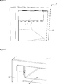
- Figure 3 — is the partial perspective view of the body and the compartment.
- Figure 4 – is the perspective view of the cover and the locking mechanism.
- Figure 5 — is the exploded view of the cover.
- the cooling device (1) comprises a body (2), at least one door (3) providing access into the body (2), at least one compartment (4) situated inside the body (2) wherein foodstuffs are placed for cooling, a cover (5) providing access into the compartment (4) and a locking mechanism (6) that provides the cover (5) to remain in the locked position by locking.
- the cover (5) remains inside the body (2) and is not seen from the outside.
- the cover (5) is opened in order to reach into the compartment (4).
- the door (3) and the cover (5) are in parallel positions with respect to one another.
- the cover (5) while open, can remain in this position and when closed, is prevented from opening automatically by being locked by means of the locking mechanism (6) ( Figure 1, Figure 2).
- the locking mechanism (6) comprises a guide (7) disposed on the body (2) so as to correspond to one side of the cover (5) while the cover (5) is closed and a latch (8) rotatably mounted on the side of the cover (5), that passes behind the guide (7) by rotating when the cover (5) is closed and prevents dislodgement of the cover (5) from the body (2).
- the latch (8) first impacts the guide (7), afterwards passes behind the guide (7) by crossing over the guide (7) with the effect of the force applied on the cover (5).
- the cover (5) is locked in the closed position and the air inside the compartment (4) is provided to be insulated effectively.
- the cover (5) is pulled slightly to the front when desired to be opened and meanwhile the latch (8) changes the cover (5) to the free position by crossing over the guide (7). Since there is no connection member that directs the cover (5) towards the closed position, the cover (5) does not have to be held to remain open. And, this provides ease of utilization (Figure 3, Figure 4).
- the latch (8) and the guide (7) have curved surfaces that make moving over one another easy.
- the corner points of the latch (8) and the guide (7) are rounded.
- the guide (7) is configured in triangle shape with rounded corners such that the base thereof is positioned to be almost parallel to the base of the compartment (4).
- the latch (8) moves between the front side and the rear side of the guide (7).
- the latch (8) moves over inclined surfaces while the cover (5) is both opened and closed by means of the triangle shape of the guide (7).
- the latch (8) comprises a head portion (16) that moves over the guide (7) while the cover (5) is opened/closed and a concave portion (17) wherein the guide (7) is seated when the cover (5) is closed.
- the head portion (16) extends downwards starting from the end of the concave portion (17) and thus when the concave portion (17) is seated on the peak point of the guide (7), the head portion (16) prevents the cover (5) from opening by bearing against the side of the guide (7) facing the rear wall of the compartment (4).
- the concave portion (17) is released from the peak point of the guide (7) and the head portion (16) crosses over the peak point by going backwards from the side borne against and resumes its free position.
- the locking mechanism (6) comprises a biasing means (9), connected to the cover (5) from one end and to the latch (8) from the other end, applying pressure on the latch (8) at the moment the latch (8) starts to rotate so as to change the latch (8) to its initial position.
- the biasing means (9) is actuated from the moment the latch (8) starts rotating from its initial position and tries to change the latch (8) back to its initial position.
- the latch (8) that becomes free after crossing over the guide (7) changes to the initial position by effect of the prestress mean (9) and provides locking by being seated behind the guide (7) ( Figure 3).
- the locking mechanism (6) comprises a support member (10) whereon the latch (8) and the biasing means (9) are disposed.
- the cooling device (1) comprises a housing (11) arranged on the cover (5) wherein the support member (10) is seated.
- the latch (8) and the biasing means (9) are grouped into the support member (10), afterwards the support member (10) is seated into the housing (11). Consequently, the locking mechanism (6) does not have to be produced together with the cover (5) and thus both ease of production is provided and also cost advantage is maintained due to decreasing molding costs (Figure 5).
- the support member (10) is detachably disposed into the housing (11).
- the latch (8) and the biasing means (9) are also detachably mounted into the support member (10). Due to this modular structure, maintenance of the locking mechanism (6) is facilitated.
- the cooling device (1) comprises at least one detent means (12) disposed on the support member (10) and at least one recess (13) arranged on the housing (11), wherein the detent means (12) is placed for providing the support member (10) to be fixed to the cover (5).
- the detent means (12) is ramp shaped and of resilient configuration. While the support member (10) is being placed into the housing (11), the detent means (12) moves along the recess (13) from the place whereat the slope begins until the maximum section and is seated into the recess (13) by being released from the surface of the housing (11) at the point of exact alignment with the recess (13).
- the detent means (12) prevents dislodgment of the support member (10) after the support member (10) is disposed into the housing (11) by means of its ramp shape and thus a strong connection is maintained (Figure 5).
- the cooling device (1) comprises a resilient protrusion (15) disposed at the rear surface of the guide (7) that provides the guide (7) to be fixed to the body (2). While the guide (7) is mounted to the body (2), the protrusion (15) is compressed from both sides and is inserted into the housing wherein it will be disposed. When released, the protrusion (15) presses on the walls of the housing wherein it is disposed by returning to its initial position due to its resilient structure and provides the guide (7) to be fixed.
- the guide (7) and the protrusion (15) are produced from different materials.
- the cover (5) is rectangular that opens and closes by rotating around one of its sides.
- the locking mechanism (6) is disposed on the side opposite to the side where the rotational axis of the cover (5) passes.
- the cover (5) is fixed rotatably to the body (2) preferably from one of its short sides and the locking mechanism (6) is disposed at the center section of the other short side.
- the cover (5) opens in the same direction as the door (3).
- the door (3) when closed, provides to close the cover (5) by applying force thereon. Consequently, damaging of the cover (5) and/or the compartment (4) remaining open is prevented.
- the cooling device (1) comprises the compartment (4) having freezing features, disposed at the upper part of the body (2), wherein objects to be frozen are placed, a fresh food compartment (14) disposed under the compartment (4), wherein objects to be cooled are placed, a cover (5) providing access into the compartment (4) and a door (3) providing access into the body (2).
- the cooling device (1) is a single door refrigerator.
- the fresh food compartment (14) and the compartment (4) having temperature difference therebetween are used effectively inside the same body (2) by means of the cover (5) ( Figure 1).
- the cover (5) is closed firmly and the compartment (4) air is prevented from mixing into other sections inside the body (2).
- the locking mechanism (6) configuration the cover (5) is opened/closed easily and can remain open while the compartment (4) is used, without requiring any intervention.(6).
Landscapes
- Engineering & Computer Science (AREA)
- Chemical & Material Sciences (AREA)
- Combustion & Propulsion (AREA)
- Physics & Mathematics (AREA)
- Mechanical Engineering (AREA)
- Thermal Sciences (AREA)
- General Engineering & Computer Science (AREA)
- Devices That Are Associated With Refrigeration Equipment (AREA)
- Cold Air Circulating Systems And Constructional Details In Refrigerators (AREA)
Abstract
La présente invention concerne un dispositif de refroidissement (1) comprenant un corps (2), au moins une porte (3) qui permet d'accéder dans le corps (2), au moins un compartiment (4) disposé à l'intérieur du corps (2) et dans lequel sont placés des aliments à refroidir, un portillon (5) permettant d'accéder au compartiment (4) et un mécanisme de verrouillage (6) qui permet au portillon (5) de rester en position verrouillée, le portillon (5) pouvant être ainsi utilisé de manière efficace au moyen du mécanisme de verrouillage (6).
Priority Applications (1)
| Application Number | Priority Date | Filing Date | Title |
|---|---|---|---|
| EP12799113.1A EP2798287B1 (fr) | 2011-12-26 | 2012-11-30 | Dispositif de refroidissement comprenant un mécanisme de verrouillage |
Applications Claiming Priority (2)
| Application Number | Priority Date | Filing Date | Title |
|---|---|---|---|
| TR201112957 | 2011-12-26 | ||
| TRA2011/12957 | 2011-12-26 |
Publications (2)
| Publication Number | Publication Date |
|---|---|
| WO2013098038A2 true WO2013098038A2 (fr) | 2013-07-04 |
| WO2013098038A3 WO2013098038A3 (fr) | 2013-09-12 |
Family
ID=47351598
Family Applications (1)
| Application Number | Title | Priority Date | Filing Date |
|---|---|---|---|
| PCT/EP2012/074088 Ceased WO2013098038A2 (fr) | 2011-12-26 | 2012-11-30 | Dispositif de refroidissement comprenant un mécanisme de verrouillage |
Country Status (3)
| Country | Link |
|---|---|
| EP (1) | EP2798287B1 (fr) |
| PL (1) | PL2798287T3 (fr) |
| WO (1) | WO2013098038A2 (fr) |
Cited By (1)
| Publication number | Priority date | Publication date | Assignee | Title |
|---|---|---|---|---|
| US10101078B2 (en) | 2013-07-10 | 2018-10-16 | Arcelik Anonim Sirketi | Refrigerator comprising an ice cream making machine |
Citations (3)
| Publication number | Priority date | Publication date | Assignee | Title |
|---|---|---|---|---|
| DE8530507U1 (de) | 1985-10-28 | 1985-12-12 | Bosch-Siemens Hausgeräte GmbH, 8000 München | Schließvorrichtung für eine Gefrierfachtür |
| DE3613439A1 (de) | 1986-04-21 | 1987-10-22 | Bosch Siemens Hausgeraete | Kuehlgeraet, insbesondere zweitemperaturen-kuehlschrank |
| WO2003018943A1 (fr) | 2001-08-24 | 2003-03-06 | Arcelik, A.S. | Mecanisme de verrouillage |
Family Cites Families (4)
| Publication number | Priority date | Publication date | Assignee | Title |
|---|---|---|---|---|
| DE7631103U1 (de) * | 1976-10-05 | 1977-06-30 | Bosch-Siemens Hausgeraete Gmbh, 7000 Stuttgart | Verschluss fuer eine an einem kastenfoermigen behaelter angeordnete tuer, insbesondere gefrierfachtuer fuer einen kuehlschrank o.dgl. |
| DE9017146U1 (de) * | 1990-12-19 | 1991-03-14 | BSH Bosch und Siemens Hausgeräte GmbH, 81669 München | Verschlußvorrichtung für eine an einem kastenartigen Behälter angeordnete Tür |
| IT240884Y1 (it) * | 1996-09-16 | 2001-04-11 | Candy Spa | Dispositivo di bloccaggio per una porta di un vano di unelettrodomestico,particolarmente per la sportello dello scomparto |
| DE202006007722U1 (de) * | 2006-05-15 | 2006-07-13 | BSH Bosch und Siemens Hausgeräte GmbH | Kältegerät |
-
2012
- 2012-11-30 WO PCT/EP2012/074088 patent/WO2013098038A2/fr not_active Ceased
- 2012-11-30 PL PL12799113T patent/PL2798287T3/pl unknown
- 2012-11-30 EP EP12799113.1A patent/EP2798287B1/fr active Active
Patent Citations (3)
| Publication number | Priority date | Publication date | Assignee | Title |
|---|---|---|---|---|
| DE8530507U1 (de) | 1985-10-28 | 1985-12-12 | Bosch-Siemens Hausgeräte GmbH, 8000 München | Schließvorrichtung für eine Gefrierfachtür |
| DE3613439A1 (de) | 1986-04-21 | 1987-10-22 | Bosch Siemens Hausgeraete | Kuehlgeraet, insbesondere zweitemperaturen-kuehlschrank |
| WO2003018943A1 (fr) | 2001-08-24 | 2003-03-06 | Arcelik, A.S. | Mecanisme de verrouillage |
Cited By (1)
| Publication number | Priority date | Publication date | Assignee | Title |
|---|---|---|---|---|
| US10101078B2 (en) | 2013-07-10 | 2018-10-16 | Arcelik Anonim Sirketi | Refrigerator comprising an ice cream making machine |
Also Published As
| Publication number | Publication date |
|---|---|
| PL2798287T3 (pl) | 2017-11-30 |
| WO2013098038A3 (fr) | 2013-09-12 |
| EP2798287A2 (fr) | 2014-11-05 |
| EP2798287B1 (fr) | 2017-06-21 |
Similar Documents
| Publication | Publication Date | Title |
|---|---|---|
| US10126041B2 (en) | Refrigerator | |
| EP3333518B1 (fr) | Réfrigérateur | |
| EP2770284B1 (fr) | Réfrigérateur | |
| KR101618128B1 (ko) | 냉장고 | |
| KR101774070B1 (ko) | 냉장고 | |
| CA1311789C (fr) | Casier pour refrigerateur | |
| EP2613114B1 (fr) | Réfrigérateur doté d'un récipient de stockage | |
| EP3008268B1 (fr) | Dispositif de fixation | |
| EP3150946B1 (fr) | Réfrigérateur comportant un dispositif de verrouillage pour seau à glace et procédé pour installer un tel dispositif | |
| WO2009061092A2 (fr) | Récipient pour réfrigérateur | |
| EP2798287B1 (fr) | Dispositif de refroidissement comprenant un mécanisme de verrouillage | |
| US9316429B2 (en) | Cooling device comprising a door opening mechanism | |
| KR101637351B1 (ko) | 얼음보관함 어셈블리 및 이를 구비하는 냉장고 | |
| KR101696817B1 (ko) | 아이스버킷 록킹장치를 갖는 냉장고 및 아이스버킷 록킹장치의 설치 방법 | |
| CN222480904U (zh) | 冰箱 | |
| JPH0486473A (ja) | 冷凍冷蔵ショーケース | |
| KR19990029032U (ko) | 냉장고 | |
| KR20070041003A (ko) | 밀폐 기구용 도어의 개방 각도 정지 장치 | |
| KR20160148967A (ko) | 아이스버킷 록킹장치를 갖는 냉장고 및 아이스버킷 록킹장치의 설치 방법 | |
| KR20120061505A (ko) | 냉장고용 전판커버 |
Legal Events
| Date | Code | Title | Description |
|---|---|---|---|
| WWE | Wipo information: entry into national phase |
Ref document number: 2014/05628 Country of ref document: TR |
|
| REEP | Request for entry into the european phase |
Ref document number: 2012799113 Country of ref document: EP |
|
| WWE | Wipo information: entry into national phase |
Ref document number: 2012799113 Country of ref document: EP |
|
| 121 | Ep: the epo has been informed by wipo that ep was designated in this application |
Ref document number: 12799113 Country of ref document: EP Kind code of ref document: A2 |