WO2013100546A1 - 센서장치 및 이를 포함하는 냉각설비의 성능 평가장치 - Google Patents
센서장치 및 이를 포함하는 냉각설비의 성능 평가장치 Download PDFInfo
- Publication number
- WO2013100546A1 WO2013100546A1 PCT/KR2012/011442 KR2012011442W WO2013100546A1 WO 2013100546 A1 WO2013100546 A1 WO 2013100546A1 KR 2012011442 W KR2012011442 W KR 2012011442W WO 2013100546 A1 WO2013100546 A1 WO 2013100546A1
- Authority
- WO
- WIPO (PCT)
- Prior art keywords
- sensor
- space
- sensor device
- housing
- fluid
- Prior art date
- Legal status (The legal status is an assumption and is not a legal conclusion. Google has not performed a legal analysis and makes no representation as to the accuracy of the status listed.)
- Ceased
Links
Images




Classifications
-
- G—PHYSICS
- G01—MEASURING; TESTING
- G01M—TESTING STATIC OR DYNAMIC BALANCE OF MACHINES OR STRUCTURES; TESTING OF STRUCTURES OR APPARATUS, NOT OTHERWISE PROVIDED FOR
- G01M99/00—Subject matter not provided for in other groups of this subclass
-
- B—PERFORMING OPERATIONS; TRANSPORTING
- B05—SPRAYING OR ATOMISING IN GENERAL; APPLYING FLUENT MATERIALS TO SURFACES, IN GENERAL
- B05B—SPRAYING APPARATUS; ATOMISING APPARATUS; NOZZLES
- B05B15/00—Details of spraying plant or spraying apparatus not otherwise provided for; Accessories
- B05B15/50—Arrangements for cleaning; Arrangements for preventing deposits, drying-out or blockage; Arrangements for detecting improper discharge caused by the presence of foreign matter
-
- G—PHYSICS
- G01—MEASURING; TESTING
- G01L—MEASURING FORCE, STRESS, TORQUE, WORK, MECHANICAL POWER, MECHANICAL EFFICIENCY, OR FLUID PRESSURE
- G01L1/00—Measuring force or stress, in general
- G01L1/02—Measuring force or stress, in general by hydraulic or pneumatic means
-
- G—PHYSICS
- G01—MEASURING; TESTING
- G01L—MEASURING FORCE, STRESS, TORQUE, WORK, MECHANICAL POWER, MECHANICAL EFFICIENCY, OR FLUID PRESSURE
- G01L19/00—Details of, or accessories for, apparatus for measuring steady or quasi-steady pressure of a fluent medium insofar as such details or accessories are not special to particular types of pressure gauges
- G01L19/0007—Fluidic connecting means
- G01L19/0046—Fluidic connecting means using isolation membranes
-
- B—PERFORMING OPERATIONS; TRANSPORTING
- B05—SPRAYING OR ATOMISING IN GENERAL; APPLYING FLUENT MATERIALS TO SURFACES, IN GENERAL
- B05B—SPRAYING APPARATUS; ATOMISING APPARATUS; NOZZLES
- B05B12/00—Arrangements for controlling delivery; Arrangements for controlling the spray area
- B05B12/004—Arrangements for controlling delivery; Arrangements for controlling the spray area comprising sensors for monitoring the delivery, e.g. by displaying the sensed value or generating an alarm
- B05B12/006—Pressure or flow rate sensors
-
- B—PERFORMING OPERATIONS; TRANSPORTING
- B05—SPRAYING OR ATOMISING IN GENERAL; APPLYING FLUENT MATERIALS TO SURFACES, IN GENERAL
- B05B—SPRAYING APPARATUS; ATOMISING APPARATUS; NOZZLES
- B05B12/00—Arrangements for controlling delivery; Arrangements for controlling the spray area
- B05B12/08—Arrangements for controlling delivery; Arrangements for controlling the spray area responsive to condition of liquid or other fluent material to be discharged, of ambient medium or of target ; responsive to condition of spray devices or of supply means, e.g. pipes, pumps or their drive means
- B05B12/082—Arrangements for controlling delivery; Arrangements for controlling the spray area responsive to condition of liquid or other fluent material to be discharged, of ambient medium or of target ; responsive to condition of spray devices or of supply means, e.g. pipes, pumps or their drive means responsive to a condition of the discharged jet or spray, e.g. to jet shape, spray pattern or droplet size
-
- B—PERFORMING OPERATIONS; TRANSPORTING
- B22—CASTING; POWDER METALLURGY
- B22D—CASTING OF METALS; CASTING OF OTHER SUBSTANCES BY THE SAME PROCESSES OR DEVICES
- B22D11/00—Continuous casting of metals, i.e. casting in indefinite lengths
- B22D11/16—Controlling or regulating processes or operations
- B22D11/22—Controlling or regulating processes or operations for cooling cast stock or mould
- B22D11/225—Controlling or regulating processes or operations for cooling cast stock or mould for secondary cooling
Definitions
- Slab manufactured by a continuous casting process and subjected to a heating furnace is produced as a thick plate material having a predetermined thickness through rough rolling (R M) and finish rolling (FM).
- slabs (Slab) produced by the continuous casting process is heated to the target temperature according to the steel grade in the furnace 310, and the furnace After passing the raw material, the raw material is rolled to a predetermined thickness, for example, the thickness of the final product through the rolling step 320 of rough rolling and finish rolling to produce a thick plate material.
- a predetermined thickness for example, the thickness of the final product through the rolling step 320 of rough rolling and finish rolling to produce a thick plate material.
- the thick plate material (S) rolled to a predetermined plate thickness through the rolling passes through the accelerated cooler 200 for the control of grain refinement or transformation structure.
- the optimization conditions are set from the heating furnace 310 to the accelerated cooler 200, and the facility management and the temperature unevenness of the rolled material (thick plate material) S are caused.
- the process of removing the factor is required, and among the factors causing such temperature unevenness, it is related to the material temperature control in the accelerated cooler 200 shown in FIGS.
- the accelerated cooler 200 although schematically shown in the drawing is composed of four to seven banks (210a to 210d), each of the unit banks each of 4-6 It is composed of a cooling header, that is, upper and lower headers 220 and 230.
- the nozzles 240 forming the liquid column are arranged in a line with about 1000 intervals.
- the nozzles 240 provided in the headers of the accelerated cooler 200 are likely to cause clogging of the nozzles and the injection holes (spray holes) due to the ionization difference of the components and the heating and cooling.
- clogging of the nozzle of the header is caused by the scale mainly caused by deterioration blocking the hole.
- the thick plate S is cooled to the target cooling temperature (FCT). This becomes difficult or results in poor cooling.
- the internal pressure of the equipment of the accelerated cooler is increased to cause a failure of related components such as a pipe, a meter, and a pump.
- the nozzle liquid column was photographed using a camera, and the image was analyzed, or the length of the liquid column poured from the nozzle by manual measurement was measured to evaluate whether the nozzle was operating normally.
- the applicant of the present invention has proposed the present invention that makes it possible to easily grasp the performance of the facility in a quick and quantitative manner in the cooling water in particular, the header nozzle state of the header nozzle of the accelerated cooler.
- the sensor device which enables the evaluation of the water injection state of the present invention described below is not necessarily applied only to a cooling facility, but generates a qualitative or quantitative signal upon application of pressure due to the impact of harmful liquid or gas. Since it is a structure, it is also possible to use it for confirmation of a gas leak or a liquid leak. However, the following description of the present invention will be described with reference to the header nozzle of the accelerated cooler.
- a housing including a fluid space
- a membrane member which is provided in the housing and induces a volume change of the fluid space upon impact or contact of a pressure applying material
- Sensor means provided in a housing in communication with the fluid space
- It provides a sensor device configured to include.
- the present invention as another technical aspect, the sensor mounting means provided on the cooling header side provided on the movement path of the material to be cooled and the nozzle;
- the sensor device provided in the sensor mounting means to be arranged corresponding to the nozzle;
- It provides a performance evaluation device of the cooling installation comprising a sensor device configured to include.
- a sensor configuration that enables the construction of a quantitative signal and data, as well as a qualitative response to pressure applied during a collision (contact) of a liquid, a gas, a liquid column of the nozzle, or a jet of the nozzle. make it possible.
- the present invention implements the temperature control of the working fluid, that is, the gas or air, which transmits the applied pressure to the sensor, so as to prevent the measurement error (error) by making the density change of the gas constant according to the coolant or the ambient air temperature.
- the measurement error error
- the present invention is to fill the operating space with an incompressible fluid (liquid) without a density change with temperature to enable a stable and quantitative evaluation without being affected by temperature.
- 1 is a process diagram showing a known thick plate manufacturing process
- FIG. 2 is a schematic view of a cooler (accelerator cooler) in FIG.
- FIG. 3 is a configuration diagram showing a use state and an operating state of the sensor device of the first embodiment according to the present invention
- FIG. 4 is a partially cutaway perspective view of the inventive device of FIG.
- FIG. 5 is a block diagram showing the sensor device of the present invention of FIG.
- 6a to 6c are schematic diagrams and graphs showing the operation concept of the sensor device of the present invention.
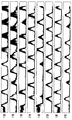
- FIG. 7 is a graph showing measurement data as an example of use of the sensor device of the present invention.
- 13 to 14 is an assembled state and exploded view showing a sensor block based on the sensor devices of the present invention
- 15a to 15b is a block diagram showing the performance evaluation device of the cooling equipment using the sensor block of the present invention and a block diagram showing the M-type sensor mounting means
- 16a and 16b is an operational state diagram and a front view showing a deployment type sensor mounting means is mounted on the sensor block of the present invention
- 17 to 19 is an overall configuration diagram showing the masking type sensor mounting means mounted on the sensor block of the present invention and front and planar configuration diagram
- 26 to 30 show various forms of the sensor device of the third embodiment according to the present invention.
- FIGS. 1 to 19 show various forms of sensor mounting means based on the sensor device of the first embodiment and the sensor device of the first embodiment according to the present invention
- FIGS. 20 to 25 show the second embodiment of the present invention
- Various forms of the sensor device of the embodiment are shown
- FIGS. 26 to 30 show various forms of the sensor device of the third embodiment.
- the sensor device 1 of the first embodiment since the basic structure of the sensor device is the same, the sensor device 1 of the first embodiment will be described in detail, and the description of the sensor devices of the second and third embodiments will be described. In the following, description of the components described in the sensor device of the first embodiment is brief.
- FIGS. 3 to 5 show the sensor device 1 of the first embodiment according to the present invention.
- the sensor device 1 of the first embodiment according to the present invention includes an incompressible gas (air), a compressible gas, or an incompressible fluid (liquid, water,
- a housing 10 including a fluid space 12 for receiving a working fluid such as oil, mercury, etc., and a membrane member 30 provided to seal the fluid space to the housing, and to which a pressure applying material is applied (collides).
- a sensor means 50 provided in the housing so as to communicate with the fluid space 12 and provided to measure pressure when the membrane member collides with the pressure applying material.
- the pressure applying substance is applied to the cooling header, that is, the upper header 220 of the gas, liquid, cooling facility, that is, the accelerated cooler 200. It may be provided as a liquid column (W) or sprayed water injected from the nozzle 240 provided.
- the pressure-applying material is a liquid column (W) to be injected from the nozzle 240 of the upper header 220 of the accelerated cooler 200 described above, as shown in Figure 3 and 5 ( It demonstrates only to water column) (or injection water).
- the sensor means is described as a pressure sensor 50.
- the working fluid filled in the fluid space 12 provided in the housing 10 as long as it is possible to measure the pressure (change amount) via the pressure sensor 50 in response to the volume change, for example
- an incompressible gas that can be applied to the sensor device of the first and second embodiments that is, gas or air, preferably air, or an incompressible fluid that can be applied to the sensor device of the third embodiment, that is, water, oil, mercury, etc.
- a specific compressible gas for a particular purpose may be filled in the fluid space 12.
- the sensor device 1 of the present invention when the liquid column (W) is normally watered from the upper header 220, collide with the membrane member 30 of the sensor device, at this time Since the membrane member 30 is a thin film. Concave in the opposite direction of the collision.
- the impact force of the liquid column is determined whether the liquid column is normally being poured in the nozzle 240, or as described above, the liquid bottle is not pumped at a normal flow rate while the nozzle 240 is partially or entirely blocked, or the liquid bottle itself is the membrane member 30. ), The measured value measured by the pressure sensor 50 is different.
- the pressure sensor 50 has a quick reaction time, as shown in FIG. 7 below, the pressure change amount can be measured precisely.
- the fluid in the fluid space 12 depends on the degree of sagging of the membrane member 30. That is, the flow amount of air or water increases, and the pressure sensor measures the pressure value (generates a voltage signal).
- the membrane member 30 of the sensor device 1 of the present invention is preferable that the material and thickness is appropriate, for example, may be provided in urethane, silicon or stainless steel, the preferred thickness of the membrane member is 0.5 It is in the range of 1.5 mm.
- the sensor's reaction sensitivity is excellent, but durability is lowered.
- the thickness of the membrane member 30 is thicker than 1.5mm, the durability is secured, but the deflection amount is small when the pressure-inducing substance collides. Speed or sensitivity will drop.
- the overall life may be a short problem.
- the membrane member 30 may be advantageous in view of securing durability and repeated return to the initial position after the liquid column impact, such as repeated collision of the liquid column.
- the housing 10 includes a sensor space 14 in which the pressure sensor 50 is embedded.
- an upper plate 16 for pressing the membrane member 30 from the upper side of the housing 10 is assembled, and the upper plate 16 provides a space where the liquid column W collides with the membrane member 30.
- the opening 16a is provided.
- bolt fastening holes 16b are formed around the opening 16a of the upper plate 16, and bolt fastening holes 16c are formed in the housing 10.
- the upper plate is assembled to the housing in a pressing state surrounding the membrane member (30).
- the membrane member is pressed around the opening of the top plate, the membrane member is actually provided as a single member (see 30 'in FIG. 14), and the structure is exposed only at the opening of the top plate, thus providing uniform operating performance. to provide.
- the membrane member 30 As shown in FIGS. 4 and 5, when the pressure-applying material, that is, the liquid column W injected from the nozzle of the upper header collides with the membrane member 30, the membrane member 30 sag momentarily, and at this time, the fluid As the volume of the space 12 changes, the fluid, for example, air or water, is compressed to allow the pressure to be measured by the pressure sensor 50 in the lower portion.
- the fluid for example, air or water
- the substrate 52 on which the pressure sensor 50 is mounted may be mounted under the housing, and the connection cable 54 may be connected to an external device, that is, the controller C, through the socket 56.
- a circuit board 52 on which pressure sensors 50 are mounted is provided between the lower plate 18 and the pressure sensor seating part 14 of the housing 10. It may be connected to the connector 56 to enable an external electrical connection. Alternatively, the cables 54 may be connected to the connector 56.
- the sensor device 1 of the present invention is capable of continuously measuring the minute pressure difference caused by the collision of the membrane member of the liquid column.
- the fluid space 12 is provided between the fluid space 12 and the pressure sensor 50 provided in the housing 10 of the sensor device 1 of the present invention. It is to form a passage (12a) is reduced in volume (cross-sectional area) compared to).
- the liquid column W when the liquid column W is normally poured in the upper header 220, the liquid column continuously collides normally with the membrane member 30 of the sensor device 1 of the present invention. Therefore, in the graph, the voltage per hour, that is, the electrical signal generated by the pressure sensor 50 generates a straight line output signal.
- the cooling system It is possible to evaluate the performance state of the nozzle, that is, the performance state of the nozzle.
- the sensor device 1 of the present invention can evaluate the normal liquid column W, the abnormal liquid column W ', and the like which are fed through the nozzle 240 of the cooling header 220.
- the liquid column is pumped normally, the water flow direction is not normal (FIG. 6C), so there is no reaction through the sensor device 1, and as a result, as shown in FIGS. 5 and 6C, only the membrane member is pumped.
- the liquor may collide with the 30.
- the sensor device 1 of the present invention makes it possible to evaluate the complete blockage of the nozzle depending on whether the liquid column W normally collides with the membrane member 30 of the sensor device 1, and even if the liquid column is water-filled. The case where the flow rate is not normal or forms a discontinuous liquid column can also be evaluated.
- Figure 7 shows a quantitative evaluation state of the cooling equipment through the sensor device 1 of the present invention in a graph.
- the sensor device 1 of the present invention it is possible to evaluate the performance state of the nozzles of the header and, as a result, to enable the performance evaluation of the cooling equipment, for example, an acceleration cooler.
- the sensor device 1 of the present invention and the sensor block 1 'including a plurality of them will enable the optimal design of the control cooling of the cooling equipment in accordance with the material and cooling conditions of the thick plate.
- the measured values for moving the sensor blocks 1 ′ in which the sensor devices 1 are arranged in two rows under the cooling header 220 are shown in a graph.
- the arrangement of the sensor devices of such a sensor block can be adjusted appropriately.
- the fluid space 12 will be described as a gas space 12 filled with air or gas.
- the operating tube 20 may actually have a structure in which the outer tube is connected to a passage (hole) formed through the housing, the air in the gas space 12 in the operating tube It may be provided with a control valve for sucking the air into a vacuum atmosphere, or on the contrary to supply air for the return of the membrane member.
- operation tube 20 may be configured in conjunction with a vacuum pump or air blowing (not shown).
- the gas body space 12 provided in the housing 10 may be filled with the compressible gas G to improve the reaction sensitivity of the sensor.
- the compressible gas G For example, when helium (He) or nitrogen (N 2 ) is filled, when the liquid column (W) collides with the membrane member 30 may improve the reaction sensitivity of the pressure sensor 50.
- the sealing means 80 provided in the sensor device of the third embodiment described in FIGS. It is desirable to maintain the sealability.
- the sealing member may be formed in the seating groove 10a of the housing around the gas space, and the sealing member of the pating or the O-ring may be mounted to prevent gas leakage between the membrane member 30 and the housing.
- the partition member 32 may be integrally provided in the lower portion of the membrane member 30 to the inside of the gas space 12 of the present invention.
- the strength of the central portion 30a where the liquid column W mainly collides is made of a material that is harder than the outer edge portion 30b that is integrated with the outer edge and is assembled between the housing 10 and the upper plate 16.
- the hard center portion 30a of the hard column collision sags while having a flat area, and the outer edge portion 30b that is softer or thinner than the central portion stretches elastically, 30b) facilitates the deflection, which will increase the gas (air) compressibility of the gas space 12 to increase the reaction sensitivity of the pressure sensor.
- the membrane member is quickly returned to the initial position by the elastic outer edge portion 30b.
- one or more volume reducing units 12b are formed integrally with the fluid space 12 of the housing 10.
- FIGS. 13 and 14 show various types of sensor mounting means 110, 130, 150 provided in the apparatus 100 for evaluating the performance of the cooling system according to the present invention described in FIGS. 15 to 19.
- the sensor block 1 'mounted on the top is shown in the assembled state and the disassembled state.
- the sensor block 1 ′ of FIGS. 13 and 14 is also applied to the sensor device of the second embodiment described with reference to FIGS. 20 through 25 and the sensor device of the third embodiment described with reference to FIGS. 26 through 30. It is possible.
- the housing 10 is provided as a housing block 10 ′ having a plurality of gas spaces 12, and the housing block of the present invention has a plurality of fluid spaces.
- a plurality of sensor spaces 14 in communication with 12 are provided.
- a plurality of pressure sensors 50 are embedded in the housing, these pressure sensors 50 are assembled and set in one substrate 52, and the substrate 52 is mounted at the bottom of the housing, An elongated lower plate 18 'is assembled to the housing block 10'.
- the extended membrane member 30 ' is attached to the upper portion of the housing block 10' to seal the spaces 12 of air, gas, or incompressible fluid, and the openings 16a are formed thereon.
- An elongated top plate 16 ' is assembled, which compresses while surrounding the membrane member 30' with the exposed area.
- the membrane member is assembled to the housing as bolts B are fastened to the housing block 10 '. .
- the elongated lower plate 18 ' is fastened as a nut N through the housing block 10' at both ends thereof, and in particular, the assembly of the housing block 10 'and the lower plate 18' is assembled.
- O-rings are interposed at least on both sides to prevent water from penetrating between at least the housing block and the lower plate.
- the sensor block 1 ' is used in the performance evaluation apparatus 100 of the cooling facility such as the accelerated cooler 200, the water density of the housing block 10' and the upper and lower plates 16 'and 18'. need.
- the upper plate 16 ' is fastened to the housing block with the upper portion of the sensor block, and the bolt B for pressing and fixing the membrane members 30' is also interposed with a packing for watertightness. It is preferable to make it so that it may be assembled, and it is preferable to set it as the structure which makes water as possible as possible the head part.
- the performance evaluation device 100 of the cooling installation of the present invention one or more sensor blocks (1 ') in which a plurality of units of the sensor device 1 described above is arranged. It may include a sensor mounting means (110).
- the pressure sensor 50-> substrate 52 of the sensor block 1 ' is mounted on a sensor mounting means (see 110 in FIG. 15) in which one or more sensor blocks 1' are mounted.
- FIGS. 15B and 16 to 19 illustrate various forms of sensor mounting means in which at least one sensor block 1 ′ is mounted in the performance evaluation apparatus 100 of the cooling system according to the present invention and moved below the upper header. It is shown.
- the L-type sensor mounting means 110 of the present invention is seated on an L guide 112 connected to the upper header 220, and a screw bar driven by a motor (not shown).
- 116 includes a moving block 114 is fastened, the moving block 114 is connected to the sensor mounting block 118 is mounted at least one sensor block (1 '), the sensor mounting block 118 is the upper It extends in correspondence with the width length of the header, and the sensor mounting block is equipped with one or more pre-designed sensor blocks 1 '.
- the moving block 114 moves in the longitudinal direction from the lower portion of the upper header along the LM guide 112, and the sensor device 1 of the sensor blocks 1 '
- the pressure is continuously measured to evaluate the performance of the nozzle of the cooling system.
- the sensor-mounted blocks of the deployment type sensor mounting means 130 further includes guide rollers (134a) (136a) provided to facilitate the movement for deployment and overlap of the blocks.
- Guides 142 are provided in the center of the blocks.
- the driving source 140 ie, the horizontal driving cylinder
- the connected front sensor mounting block 136 sequentially deploys the trailing sensor mounting blocks and reverses them, and deploys the sensor block 1 ′.
- Quantitative evaluation of the liquid column through the sensor block 1 ′ is performed according to the deployment or overlap of the sensor mounting blocks 132, 134, 136.
- deployment type sensor mounting means 130 of FIG. 16 since a plurality of sensor blocks 1 ′ are mounted in multiple stages, it is advantageous to apply to a large capacity cooling facility, and the deployment type sensor mounting means 130 is illustrated. Not shown movement means, for example, can be moved by itself in connection with the L-type transfer unit and the like not shown.
- FIGS. 17 to 19 show another type of sensor mounting means, that is, a masking type sensor mounting means 150 provided in the performance evaluation apparatus 100 of the cooling system according to the present invention.
- the masking-type sensor mounting means 150 of the present invention known masking means 170 to block the water in both sides in response to the width of the thick plate in the cooling equipment in the header Is provided in conjunction with
- the masking plate of the masking means 170 is not shown.
- the masking sensor mounting means 150 is provided in such a manner that the cylinders 152 and 154 of the multi-stage are horizontally mounted and movable in association with the vertical moving plate 178 of the edge masking means 170.
- the edge masking means 170 blocks the liquid column W injected in the longitudinal direction of the upper header 220 corresponding to the width of the steel sheet, and is disposed on the upper portion of the upper header 220.
- a moving plate 178 extending downward is connected to a moving block 176 that is elongated and provided in two stages and fastened to a screw bar 174 that is rotationally driven as a motor 172, and the moving plate 178 is Rollers 177 may be provided to move along the rail 175 provided in the upper header.
- the base 152 of the masking sensor mounting means 150 is connected to the lower end of the moving plate 178, and the base is provided with two-stage cylinders and a sensor mounting plate.
- the second cylinder 158 connected as the moving plate 156 to the tip rod is advanced, and corresponds to the stroke of the first cylinder.
- the second cylinder 158 which has been advanced in length, is advanced again, and as a result, the sensor block 1 'provided to the upper sensor block mounting plate 160 associated with the second cylinder has a liquid column membrane member 30 of the sensor device. Collide with ') and deploy to the location where performance is evaluated.
- the first and second cylinders are retracted and returned on the base to their original positions, and the moving plate 178 of the edge masking means 170 moves, as shown in FIG. 17. At the end of the cooling header, it is waiting to move.
- the construction of the first and second cylinders of the second stage is to provide a sufficient forward stroke of the sensor block, since the operating stroke of one cylinder is limited.
- the base 152 of the masking sensor mounting means 150 may be provided as a blocking plate function to block the radiant heat from affecting the sensor block 1 '.
- the sensor block 1 ′ is cooled through the various types of sensor mounting means shown in FIGS. 15 to 19, that is, the upper header 220 in the width direction of the upper header 220. Quantitative and precise, based on the state of the liquid column and jet water injected or sprayed from the nozzle, that is, the nozzle state, and consequently, the performance of the cooling system in real time. It can be evaluated.
- the sensor device 1 of the second embodiment may be provided to the sensor mounting means 110, 130, 150.
- the sensor device 1 of the second embodiment of the present invention may be blocked.
- the sensor block 1 ′ may be mounted and used in the sensor mounting means, and such a sensor mounting means 110 is as described above with reference to FIGS. 15B to 19, and the detailed description thereof is briefly described in the present embodiment.
- the fluid space 12 described above is limited to the gas space 12.
- the sensor device 1 of the second embodiment of the present invention like the sensor device 1 of the first embodiment, has a functional gas (air, such as air or gas of other specific components).
- a housing 10 having a gas space 12 and a sensor space 14 accommodated therein, a membrane member 30 to which the gas space 12 is sealed, and a pressure applying material collide with each other, and a sensor. It may be provided including a sensor 50 mounted in the space 14 provided to measure the pressure generated during the impact or contact of the membrane member of the pressure applying material.
- the basic operation of the sensor device 1 of the second embodiment of the present invention is the same as the operation of the sensor device of the first embodiment described above, and the detailed description thereof is brief in this embodiment.
- the sensor device 1 of the second embodiment of the present invention is provided in the housing 10 so as to surround at least a portion of the gas space 12 and the sensor space 14 as will be described in detail below.
- Temperature control means provided to prevent measurement errors.
- the air (gas) density of the gas space 12 changes with the change of the cooling water or the air temperature of the external atmosphere, even if the liquid column under the same conditions collides with the membrane member 30, the same deflection amount is formed,
- the measurement error (error) occurs due to the air (gas) density change in the gas space 12.
- the temperature control means provided in the sensor device of the second embodiment of the present invention is provided in the housing 10 in a form surrounding at least a portion of the gas space 12 and the sensor space 14, so that the temperature changes. It is provided to prevent measurement errors.
- the temperature control means provided in the sensor device 1 of the second embodiment of the present invention, the gas space 12 and the sensor space 14 provided in the housing 10 The housing 10 may be provided with a heat pipe 70 or a heating wire (not shown) provided to the housing 10 while surrounding at least a portion thereof to control the air (gas) temperature.
- the heat pipe 70 or the heating wire of the temperature control means surrounds both the gas space 12 and the sensor space 14 and is provided adjacent to the housing gas space surface, the passage surface, and the sensor space surface. Will be.
- the heat pipe 70 (or hot wire) of the present invention is provided in the housing 10 in a multi-layer or multi-row structure.
- the heat pipe 70 or the heating wire (not shown) of the present invention is arranged at the side and the bottom of the gas space 12 and at the top and the side of the sensor space 14, Temperature control of the internal air (gas) in the sensor space can be rapidly performed.
- the internal air temperature of at least one or both of the gas space 12 and the sensor space 14 of the sensor device 1 of the present invention is kept constant, and the air density of the gas space is not affected by the external temperature conversion. Can be kept constant, so that the sensor device can solve the measurement error (error).
- the temperature control means of the present invention corresponds to the internal space 12 (14) of the housing 10, the standard (diameter)
- the heat pipe having a large diameter is installed in multiple rows around the passage 12a, and the heat pipes 70 having a small diameter are installed in multiple layers around the gas space and the sensor space.
- the heat pipes 70 which is the temperature control means of the present invention may be provided along the lower plate 18 (unit length or extended form) of the sensor device 1, the heat pipe Lines L1 to L4, such as hot water, hot water, steam, or a heat medium, which are distributed through 70, may be provided in connection.
- the heat pipes 70 which is the temperature control means of the present invention may be provided along the lower plate 18 (unit length or extended form) of the sensor device 1, the heat pipe Lines L1 to L4, such as hot water, hot water, steam, or a heat medium, which are distributed through 70, may be provided in connection.
- this is merely an embodiment and not necessarily limited thereto.
- the temperature control means of the present invention that is, the heat pipe 70 or the heating wire, may be provided integrally planted in the housing 10, for example, when the housing 10 is molded into a heat resistant resin product,
- the heat pipe 70 of the resin pipe can be integrally inserted and manufactured.
- the housing 10 when the housing 10 is made of a non-corrosive metal material such as stainless steel, unit plates are stacked in a multi-layered manner and heat to a heat pipe or a hot wire receiving groove 71 formed in a proper arrangement. It may be possible to receive and provide the pipe 70 or the hot wire.
- the heat transfer is generated whether the housing 10 is a resin product or a stainless steel material, it is preferable to arrange the heat pipe 70 or the heat wire adjacent to the possible gas space 12 or the sensor space 14. Do.
- the housing 10 of the multilayer structure as shown in FIG. 2 may be assembled by compressing each of the unit housings with an assembly bolt B 'having an elongated length, and the bolts may be formed on the substrate 52 of the pressure sensor 50. Can penetrate through the lower plate 18.
- the heat transfer magnification provided in at least some or both of the housing surface of the gas space 12 and the sensor space 14 adjacent to the heat control device of the heat pipe 10 or the heating wire of the present invention. It may further include wealth.
- the heat transfer enlargement portion of the present invention may be provided in the form of a serrated cross-section of the riblet face 72, that is, provided in the housing wall surface of the gas space 12 or the sensor space 14, so that the gas may be provided. Increase the efficiency of keeping the temperature of the space or sensor space constant.
- the temperature control means of the present invention at least a portion of the gas space 12 and the sensor space 14, the heat insulating material 74 provided on the housing surface, and the gas inside the heat insulating material
- the temperature control means provided in the space or the sensor space, that is, the heat pipe 70 may be provided including a heating wire.
- the heat pipe 70 or the heating wire may be appropriately provided in the gas space 12 and the sensor space 14 through a suitable support.
- FIGS. 26 to 30 show the sensor device 1 according to the third embodiment of the present invention.
- the sensor device 1 of the third embodiment of the present invention is incompressible, such as water, while the space provided in the sensor device 1 of the first and second embodiments is the gas space 12 (air space). It is characterized by having a fluid space 12 in which the fluid F is at least partially filled.
- the sensor device 1 like the first and second sensor devices, includes a housing 10 having a sensor space 14 in addition to the fluid space 12, and the housing 10. It is provided to seal the fluid space (12) on the membrane member 30, the pressure application material, that is, the liquid column (W) collide, and mounted in the sensor space 14 of the housing to communicate with the fluid space 12 It may basically include a pressure sensor 50 provided to measure the pressure generated during the impact or contact of the membrane member of the pressure applying material, such as liquid column.
- the fluid space 12 provided in the sensor device of the third embodiment of the present invention basically fills at least a part of an incompressible fluid F.
- the liquid column collides with the membrane member 30.
- To form a volume change in the constant fluid space 12 to provide pressure (volume change) to the pressure sensor 50 can be provided as water, mercury, oil, etc. On the side, water is the most suitable.
- the membrane member 30 sags from the center at a pressure applied to the pressure-applying material, that is, the liquid column W while falling and colliding, and thus the sealed space.
- a volume change occurs in the phosphorus fluid space 12, and the fluid is sensed by transmitting a differential pressure to the pressure sensor 50.
- the collision force of the liquid column W makes it possible to determine whether the liquid column is normally injected in the nozzle 240 of the upper cooling header 220 of the cooler, as described above.
- the sensor device 1 of the third embodiment of the present invention is as shown in Figs. It is characterized in that it comprises a sealing means 80 or a fluid receiving means 90 provided in the housing at the boundary between the fluid space 12 and the membrane member 30.
- the sensor device 1 of the third embodiment of the present invention basically fills the fluid space 12 with the incompressible fluid F, that is, water, etc., the sealing means 80 for blocking leakage of the fluid and the like, It includes a fluid receiving means (90).
- the sensor device 1 of the third embodiment of the present invention fills the space 12 with at least a portion of an incompressible fluid F such as water, instead of gas.
- an incompressible fluid F such as water
- the sensor device 1 of the third embodiment of the present invention is the same in the basic structure as the first and second sensor devices described above.
- the housing 10 has a passage provided with a reduced volume between the fluid space 12 and the sensor space 14 to improve the sensitivity of the pressure sensor. 12a), a sensor means, that is, a pressure sensor 50, is mounted on the substrate 52 in the sensor space 14 below the passage, the substrate is assembled under the housing, and the lower plate 18 is provided below the substrate. It is assembled.
- the sensor device 1 of the third embodiment of the present invention is not shown in detail in FIGS. 26 to 30, as described in the description of the sensor device of the first embodiment, it is mounted on the sensor mounting means 110 and is equipped with a cooling device. It can be used to measure the performance evaluation of (nozzle of the upper header).
- the sensor space 14 of the housing 10 is filled.
- the inclined side may further include a first sensor sealing part 13 inclined to be in close contact with the pressure applying part 50a of the pressure sensor 50.
- the inclined surface of the pressure applying unit 50a of the pressure sensor 50 and the first sensor sealing portion 13 are in close contact with each other so that the fluid F, that is, water moves toward the sensor means. The leak to the sensor space 14 is blocked.
- the pressure sensor 50 since the sensor means of the present invention, that is, the pressure sensor 50 may be used in a very humid environment, since the outer surface is coated for waterproofing, the fluid F toward the sensor space 14 side. Even small leaks do not cause problems with sensor operation.
- the second sensor sealing portion 15 provided to be in close contact with the body 50b of the sensor means on the sensor space 14 side of the housing. ) May be further included.
- a sealing member 15a for example, a packing may be further interposed between the second sensor sealing portion 15 and the sensor body 50b.
- the internal fluid F of the fluid space 12 is externally leaked through the sealing means 80 or the fluid receiving means 90 provided on the housing 10 toward the membrane member 30. This is blocked, and the leak is blocked by the first and second sensor sealing parts 13 and 15 on the sensor space side.
- the second sensor sealing unit 15 may be integrally manufactured with the housing, and the housing may be manufactured from a metal workpiece in consideration of temperature and the like.
- the ring structure may be assembled by welding (laser welding) or the like.
- the sealing means 70 is intimately connected to at least one mounting portion 10a integrally formed in the housing 10. It may be provided as an O-ring that is filled or inserted.
- the fluid receiving means 90 may be formed as a fluid insertion groove which is sequentially provided to one or more housings adjacent to the fluid space 12.
- the fluid receiving means 90 of the fluid insertion groove has an annular ring shape at least outside the fluid space.
- One or more may be integrally formed concave in the housing.
- the fluid space 12 is not necessarily filled with an incompressible fluid F, that is, water, but only partially filled with water.
- an incompressible fluid F that is, water, but only partially filled with water.
- the rest is provided to the air space 12 'or gas space filled with air or gas, there is no problem in the operation of the sensor.
- the pressure value is adjusted through the sensor device according to the water level control, or the water level is constantly maintained in the fluid space 12. Since the operation of the sensor is constant, the fluid (water) supply and discharge passages 17a and 17b communicating with the fluid space 12 are formed in the housing 10 so that the water level is constant in the fluid space 12. It will be possible to keep it.
- the level sensor (SE) for detecting the water level of the water filled in the fluid space 12 is disposed, it is provided on the side of the fluid space, the valve of the supply line (not shown) connected to the fluid supply passage (17a) By interlocking with the control unit, the water level in the space may be more precisely maintained.
- the fluid space 12 may be filled with oil (O) or mercury instead of air and water. Do.
- a sensor structure capable of constructing qualitative signals and data as well as qualitatively corresponding to the pressure applied during a collision (contact) of a liquid, a gas, a liquid column of the nozzle, or the injection water of the nozzle. Let's do it.
Landscapes
- Physics & Mathematics (AREA)
- General Physics & Mathematics (AREA)
- Measuring Fluid Pressure (AREA)
- Testing Or Calibration Of Command Recording Devices (AREA)
Abstract
기체, 노즐에서 주수되거나 분사되는 액주 또는 분사수 등의 압력 인가체의 충돌(접촉)시 인가되는 압력에 대응하는 정성적 신호는 물론, 정량적 신호를 발생시키는 센서장치와 이를 포함하는 냉각설비의 성능 평가장치가 제공된다. 이와 같은 본 발명은 액체, 기체, 노즐의 액주 또는 노즐의 분사수 등의 충돌(접촉)시 인가되는 압력에 대응하는 정성적 신호는 물론, 정량적 신호와 데이터 구축을 가능하게 하고, 추가로 온도 변화에 따른 측정 에러를 방지시키고, 이를 기반으로 냉각설비의 성능(주수 또는 분사 상태)를 최소한 정량적으로 정밀하게 평가 가능하게 하여, 궁극적으로 냉각설비의 보수-유지와 가동성을 향상시키는 개선된 효과를 얻을 수 있다.
Description
본 발명은 센서장치 및 이를 포함하는 냉각설비의 성능 평가장치에 관한 것이며, 더욱 상세하게는 액체, 기체, 노즐의 물기둥(이하,'액주') 또는 노즐의 분사수 등의 충돌(접촉)시 인가되는 압력에 대응하는 정성적 신호는 물론, 정량적 신호와 데이터 구축을 가능하게 하고, 추가로 온도 변화에 따른 측정 오류(에러)를 방지하고, 이를 기반으로 냉각설비의 성능(주수 또는 분사 상태)를 최소한 정량적으로 정밀하게 평가 가능하게 하여, 궁극적으로 냉각설비의 보수-유지와 가동성을 향상시킨 센서장치 및 이를 포함하는 냉각설비의 성능 평가장치에 관한 것이다.
연속 주조 공정에 의해서 제조되고 가열로를 거친 슬라브(Slab)는 조압연(R M)과 마무리 압연(FM)을 거쳐 소정 두께의 후판재로 생산된다.
예를 들어, 도 1 및 도 2에서 도시한 바와 같이, 연속주조 공정에 의해서 제조된 주편 예를 들어, 슬라브(Slab)는 가열로(310)에서 강종에 따른 목표 온도까지 가열되고, 가열로를 통과한 소재는, 조압연와 마무리 압연의 압연단계(320)를 거쳐 일정한 두께 예컨대, 최종 제품의 지시 두께까지 소재를 압연하여 후판재를 생산한다.
한편, 압연을 통하여 소정의 판 두께로 압연된 후판재(S)는 결정립 미세화나 변태조직의 제어를 위하여 가속냉각기(200)를 거친다.
그리고, 압연제품(후판 제품)의 질을 높이기 위하여 교정기(330)를 통하여 열간 교정되고, 냉각대(340)에서 최종 제품으로 완성된다.
한편, 무교정 및 무변형 제품을 생산하기 위해서는 가열로(310)부터 가속냉각기(200)에 이르기까지 최적화 조건을 설정하고 설비의 관리 및 압연소재(후판재)(S)의 온도 불균일을 초래하는 인자를 제거하는 과정이 필요한데, 이와 같은 온도 불균일을 초래하는 인자 중, 도 1,2에서 도시한 가속 냉각기(200)에서의 소재 온도 제어와 관련된다.
이때, 도 2에서 도시한 바와 같이, 가속 냉각기(200)는, 도면에서는 개략적으로 도시하였지만, 4~7개의 뱅크(210a 내지 210d)들로 구성되고, 각각의 단위 뱅크들에는 각각 4~6개의 냉각헤더 즉, 상,하부 헤더(header)(220)(230)들로 구성된다.
한편, 단위 헤더 예를 들어, 상부 헤더(220)에는 액주를 형성하는 노즐(도 6c의 240)들이 대략 1000개 정도 간격과 열을 맞추어 배열되어 있다.
그런데, 이와 같은 가속냉각기(200)의 헤더들에 제공된 노즐(240)들은 그 구성성분의 이온화 차이, 가열과 냉각에 따른 노즐 내부와 출구부위(분사구멍)의 막힘 현상이 발생하기 쉽다.
예를 들어, 이와 같은 헤더의 노즐의 막힘현상은, 주로 열화로 발생된 스케일이 구멍을 막아서 발생된다.
따라서, 하나의 단위 헤더에만 상당한 양으로 설치된 노즐들 중 일부만 막히거나, 기타 이물질이나 부식 등으로 노즐의 구멍이 좁아지는 경우, 목표 냉각온도(Finish Cooling Temperature,FCT)까지 후판재(S)의 냉각이 어렵게 되거나, 냉각불량을 초래한다.
그리고, 노즐의 구멍이 막히거나 좁아지면, 가속냉각기의 설비 내부압력이 증가하여 연계된 배관, 계측기 및 펌프 등의 관련 부품의 고장을 발생시키게 된다.
따라서, 가속 냉각기의 헤더의 노즐 직경, 재질, 노즐 간격, 배관 디자인 등의 구조 개선에 대한 연구가 진행되고 있으나, 그 실효성은 크지 않은 실정이었다.
특히, 가속 냉각기의 주수상태 즉, 노즐에서부터 정상적인 액주가 형성되고 있는 지를, 자동화를 기반으로 파악하는 것은 더 어려운 문제가 있었다.
예를 들어, 종래의 경우, 카메라를 이용하여 노즐 액주를 촬영하고, 촬영된 이미지 분석이나, 수작업으로 노즐에서 주수되는 액주의 길이를 측정하여 노즐이 정상적으로 작동되고 있는 지를 평가하였다.
결국, 종래의 경우 노즐 들의 주수상태를 파악하는 데에 상당한 시간이 필요함은 물론, 실제 가속 냉각기들이 구축된 라인에서 그 작업공간이 매우 협소하고 수작업으로 이루어 지기 때문에, 정밀한 주수상태의 판단은 어려운 것이다.
이에 따라서, 본 발명의 출원인은 냉각설비 특히, 가속 냉각기의 헤더 노즐의 주수상태를 신속하고 정량적인 방법으로 설비의 성능을 쉽게 파악 가능하게 한 본 발명을 제안하게 되었다.
그러나, 다음에 설명하는 본 발명의 주수상태의 평가를 가능하게 하는 센서장치는 반드시 냉각설비에만 적용되어야 하는 것은 아니고, 유해한 액체나 기체 등의 충돌에 의한 압력 인가시 정성적 또는 정량적 신호를 발생시키는 구조이므로 가스 누출이나 액체 누출 등의 확인을 위하여 사용하는 것도 충분히 가능하다. 다만, 이하의 본 발명 설명에서는 가속 냉각기의 헤더 노즐과 관련하여 설명한다.
따라서, 당 기술분야에서는 (누출되거나 누수되는)기체, 액체 또는, 노즐에서 주수되거나 분사되는 액주와 분사수 등의 압력 인가체의 충돌(접촉)시 인가되는 압력에 대응하는 정성적 신호는 물론, 정량적 신호를 발생시키는 센서 구축을 가능하게 한 센서장치가 요구되어 왔다.
더하여, 인가되는 압력을 센서에 전달하는 기체(공기)의 온도제어를 구현하여, 냉각수나 주변 대기온도에 따른 기체의 밀도변화를 일정하게 하여 측정오류(에러)를 방지하도록 하여, 측정 정밀성 확보를 가능하게 한 센서장치가 요구되어 왔다.
추가로, 온도에 따른 밀도변화가 적거나 없는 비압축성 유체(액체, 물 등)를 작동공간에 충진시켜 온도 영향을 받지않고 안정적이고 정량적인 평가를 가능하게 한 센서장치가 요구되어 왔다.
따라서, 상기와 같은 본 발명의 센서장치를 기반으로 냉각설비의 성능(주수상태)를 정량적으로 신속하고 정밀하게 평가 가능하게 하여, 냉각 불량을 방지하고, 특히 열악하고 좁은 환경에서 자동화를 기반으로 냉각설비의 노즐상태를 파악하는 것을 가능하게 하여, 설비의 보수 및 유지 관리를 용이하게 한 냉각설비의 성능 평가장치를 제공하는 것이다.
상기와 같은 요구 사항을 달성하기 위한 기술적인 일 측면으로서 본 발명, 유체공간을 포함하는 하우징;
상기 하우징에 구비되고 압력인가물질의 충돌 또는 접촉시 유체공간의 체적변화를 유도하는 멤브레인부재; 및,
상기 유체공간과 연통하여 하우징에 제공되는 센서수단;
을 포함하여 구성된 센서장치를 제공한다.
더하여, 다른 기술적인 측면으로서 본 발명은, 냉각 대상소재의 이동경로 상에 제공되고 노즐들이 구비된 냉각헤더 측에 제공된 센서탑재수단; 및,
상기 센서 탑재수단에 상기 노즐에 대응하여 배열되도록 제공된 상기 센서 장치;
를 포함하여 구성된 센서장치를 포함하는 냉각설비의 성능 평가장치를 제공한다.
이와 같은 본 발명에 의하면, 액체, 기체, 노즐의 액주 또는 노즐의 분사수 등의 충돌(접촉)시 인가되는 압력에 대응하는 정성은 물론, 정량적 신호와 데이터 구축을 가능하게 하는 센서 구성의 구축을 가능하게 한다.
더하여, 본 발명은 인가되는 압력을 센서에 전달하는 작동유체 즉, 기체나 공기의 온도제어를 구현하여, 냉각수나 주변 대기온도에 따른 기체의 밀도변화를 일정하게 하여 측정오류(에러)를 방지하도록 하여, 측정 정밀성 확보를 가능하게 하는 것이다.
또한, 본 발명은 온도에 따른 밀도변화가 없는 비압축성 유체(액체)를 작동공간에 충진시켜 온도 영향을 받지않고 안정적이고 정량적인 평가를 가능하게 하는 것이다.
따라서, 본 발명의 센서장치를 기반으로 냉각설비의 성능(주수 또는 분사 상태)을 정량적으로 정밀하게 평가 가능하기 때문에, 열악하고 좁은 환경에서 자동화를 기반으로 냉각설비의 노즐 상태는 물론, 전체적인 냉각능력의 평가 및 파악에 매우 유리한 것이다.
결국, 본 발명은 냉각설비의 보수-유지를 용이하게 하고, 가동율을 극대화시킴은 물론, 궁극적으로 냉각 품질과 제품 품질과 생산성을 향상시키는 것이다.
도 1은 알려진 후판 제조공정을 도시한 공정도
도 2는 도 1에서 냉각기(가속 냉각기)를 도시한 개략도
도 3은 본 발명에 따른 제1 실시예의 센서장치의 사용상태와 작동상태를 도시한 구성도
도 4는 도 3의 본 발명 장치를 도시한 일부 절개 사시도
도 5는 도 3의 본 발명 센서장치를 도시한 구성도
도 6a 내지 도 6c는 본 발명 센서장치의 작동 개념을 도시한 모식도와 그래프
도 7은 본 발명 센서장치의 사용예로서 측정 데이터를 나타낸 그래프
도 8 내지 도 12는 본 발명에 따른 제 1 실시예의 센서장치의 여러 변형예들을 도시한 구성도
도 13 내지 도 14는 본 발명 센서장치들을 기반으로 한 센서블록을 도시한 조립 상태도 및 분해도
도 15a 내지 도 15b는 본 발명 센서블록을 이용한 냉각설비의 성능 평가장치를 도시한 구성도 및 엘엠형 센서탑재수단을 도시한 구성도
도 16a 및 도 16b는 본 발명 센서블록이 탑재되는 전개형 센서탑재수단을 도시한 작동 상태도 및 정면도
도 17 내지 도 19는 본 발명 센서블록이 탑재되는 마스킹형 센서탑재수단을 도시한 전체 구성도 및 정면 및 평면 구성도
도 20 내지 도 25는 본 발명에 따른 제2 실시예의 센서장치의 여러 형태를 도시한 도면
도 26 내지 도 30은 본 발명에 따른 제3 실시예의 센서장치의 여러 형태를 도시한 도면
이하, 본 발명을 상세하게 설명한다.
먼저, 도 1 내지 도 19에서는 본 발명에 따른 제1 실시예의 센서장치 및 제1 실시예의 센서장치를 기반으로 하는 센서탑재수단의 여러 형태들을 도시하고 있고, 도 20 내지 25는 본 발명의 제2 실시예의 센서장치의 여러 형태들을 도시하고 있고, 도 26 내지 도 30에서는 제3 실시예의 센서장치의 여러 형태들을 도시하고 있다.
따라서, 본 발명의 제1 내지 제3 실시예의 센서장치에서, 센서장치의 기본 구조는 동일하므로 제1 실시예의 센서장치(1)에서 상세하게 설명하고, 제2 및 제 3 실시예의 센서장치들의 설명에서는 제1 실시예의 센서장치에서 설명한 구성요소의 설명은 간략한다.
먼저, 도 3 내지 도 5에서는 본 발명에 따른 제1 실시예의 센서장치(1)를 도시하고 있다.
즉, 도 3 내지 도 5에서 도시한 바와 같이, 본 발명에 따른 제1 실시예의 센서장치(1)는, 다음에 상세하게 설명하는 비압축성 기체(공기), 압축성 가스 또는 비압축성 유체(액체, 물, 오일, 수은 등) 등의 작동유체가 수용되는 유체공간(12)을 포함하는 하우징(10)과, 상기 하우징에 유체공간을 밀폐토록 제공되되, 압력인가물질이 인가(충돌)되는 멤브레인부재(30) 및, 상기 유체공간(12)과 연통하도록 상기 하우징에 제공되고, 압력인가물질의 멤브레인부재 충돌시 압력을 측정토록 제공된 센서수단(50)을 포함하여 구성 일 예로 제공될 수 있다.
이때, 제1 실시예의 센서장치 및 다음의 제2,3 실시예의 센서장치에서, 압력인가물질은, 기체, 액체, 냉각설비 즉, 가속 냉각기(200)의 냉각헤더 즉, 상부헤더(220)에 구비된 노즐(240)에서 주수되는 액주(W) 또는 분사수 등으로 제공될 수 있다.
다만, 이하의 본 실시예에서 상기 압력인가물질은 도 3 및 도 5에서 도시한 바와 같이, 앞에서 설명한 가속 냉각기(200)의 상부헤더(220)의 노즐(240)에서 주수되는 액주(W)(물기둥)(또는 분사수)로 한정하여 설명한다.
또한, 센서수단을 이하의 설명에서는 압력센서(50)로 설명한다.
한편, 상기 하우징(10)에 제공되는 상기 유체공간(12)에 채워지는 작동유체는, 체적변화시 응답하는 압력센서(50)를 매개로 압력(변화량)의 측정을 가능하게 하는 것이면 가능한데, 예를 들어 제1,2 실시예의 센서장치에 적용될 수 있는 비압축성 기체 즉, 기체나 공기중 바람직하게는 공기나, 다음의 제3 실시예의 센서장치에 적용될 수 있는 비압축성 유체 즉, 물, 오일, 수은 등일 수 있다. 물론, 특정 목적을 위한 특정 압축성 가스를 유체공간(12)에 채워질 수 있다.
따라서, 본 발명의 센서장치(1)는 도 3 및 도 5에서 도시한 바와 같이, 상부헤더(220)에서부터 정상적으로 액주(W)가 주수되면, 센서장치의 멤브레인부재(30)에 충돌하고, 이때 멤브레인부재(30)는 얇은 막이므로. 충돌 반대방향으로 오목하게 들어간다.
결국, 액주의 충돌력은 액주가 노즐(240)에서 정상적으로 주수되고 있는지, 또는 앞에서 설명한 바와 같이, 노즐(240)이 일부 또는 전체가 막히면서 액주가 정상적인 유량으로 주수되지 않거나 액주 자체가 멤브레인부재(30)에 충돌하는 정도에 따라, 압력센서(50)에서 측정되는 측정값이 다르게 된다.
그런데, 이와 같은 압력센서(50)는, 반응시간이 빠르기 때문에, 다음의 도 7에서 알 수 있듯이, 압력 변화량을 정밀하게 측정할 수 있다.
예를 들어, 도 5에서 도시한 바와 같이, 상부헤더에서 주수되는 액주(W)가 멤브레인부재(30)에 낙하하면서 충돌하면, 멤브레인부재(30)가 처지는 정도에 따라 유체공간(12)의 유체 즉, 공기나 물의 유동량은 커지고, 압력센서에서는 압력값을 측정(전압 신호를 발생)하게 된다.
이때, 멤브레인부재(30)에 압력이 인가되지 않은 기준 압력 값을 미리 설정하면, 측정된 압력값과의 차압을 제어부에서 비교하면, 다음의 도 7과 같은 정량적인 측정 데이터의 구축도 가능하게 하는 것이다.
한편, 본 발명 센서장치(1)의 상기 멤브레인부재(30)는 그 재질과 두께가 적정한 것이 바람직한데, 예를 들어 우레탄, 실리콘 또는 스테인리스 스틸 등으로 제공될 수 있고, 멤브레인부재의 바람직한 두게께는 0.5 ∼ 1.5mm 범위이다.
즉, 상기 멤브레인부재(30)의 두께가 0.5mm 보다 얇으면 센서의 반응감도는 우수하게 되지만, 내구성이 떨어지고, 반대로 1.5mm 보다 두꺼우면, 내구성은 확보되지만 압력인가물질의 충돌시 처짐량이 적어 반응속도나 감도는 떨어지게 된다.
또한, 상기 멤브레인부재의 두께가 0.5mm 보다 작으면, 멤브레인부재의 수명이나 액주 충돌후 원래 위치로의 복귀하는 탄력성도 적어, 전반적으로 수명도 짧은 문제가 발생될 수 있다.
한편, 상기 멤브레인부재(30)는 액주의 반복 충돌에 따른 내구성의 확보와 액주 충돌후 초기 위치로의 복귀 등을 고려하면, 스테인레스 재질이 유리할 수도 있다.
다음, 도 3 내지 도 5에서 도시한 바와 같이, 본 발명 센서장치(1)에서 상기 하우징(10)에는 압력센서(50)가 내장되는 센서공간(14)를 포함한다.
그리고, 하우징(10)의 상측에는 멤브레인부재(30)를 위에서 압박하는 상부 판(16)이 조립되고, 상부판(16)에는 액주(W)가 멤브레인부재(30)에 충돌하는 공간을 제공하는 개구부(16a)가 구비되어 있다.
예를 들어, 도 27에서 도시한 바와 같이, 상기 상부판(16)의 개구부(16a)의 주변으로 볼트 체결구멍(16b)들이 형성되고, 하우징(10)에도 볼트 체결구멍(16c)들이 형성되어, 상부판은 멤브레인부재(30)를 포위하면서 압박하는 상태로 하우징에 조립되는 것이다.
물론, 상기 상부판의 개구부 주변으로 멤브레인부재를 압박하기 때문에, 멤브레인 부재는 실제로는 하나의 부재(도 14의 30' 참조)로 제공되고, 상부판의 개구부에서만 노출되는 구조이므로 균일한 작동성능을 제공한다.
도 4 및 도 5에서 도시한 바와 같이, 압력인가물질 즉, 상부헤더의 노즐에서 주수되는 액주(W)가 멤브레인부재(30)에 충돌하면, 멤브레인부재(30)는 순간적으로 처지고, 이때 유체공간(12)의 체적변화에 따라 유체 예를 들어, 공기나 물 등이 압축되면서 하부의 압력센서(50)에서 압력을 측정 가능하게 한다.
그리고, 압력센서(50)가 탑재되는 기판(52)은 하우징 하부에 장착되고, 연결 케이블(54)은 소켓(56)을 통하여 외부 기기 즉, 제어부(C)와 연계될 수 있다.
바람직하게는, 도 4와 같이, 상기 하부판(18)과 하우징(10)의 압력센서 안착부(14)사이에는 압력센서(50)들이 탑재되는 회로기판(52)이 제공되고, 상기 회로기판은 외부 전기적 연결을 가능하게 하는 콘넥터(56)와 연결될 수 있다. 또는, 케이블(54)들이 콘넥터(56)와 연결될 수 있다.
결국, 본 발명의 센서장치(1)는 액주의 멤브레인부재 충돌에 따른 미세한 압력차도 연속적으로 측정 가능하게 하는 것이다.
한편, 바람직하게는 도 4 및 도 5에서 도시한 바와 같이, 본 발명의 센서장치(1)의 상기 하우징(10)에 구비된 유체공간(12)과 압력센서(50)사이에는 유체공간(12)에 비하여 체적(단면적)이 감소되는 통로(12a)를 형성하는 것이다.
따라서, 상기 통로(12a)는 유체공간(12)에 비하여 체적이 감소되므로, 멤브레인부재(12)에 압력인가물질 즉, 액주(W)가 충돌하면 공간에 채워진 유체 즉, 공기는 공간의 체적변화로 유동되고 상기 좁아진 통로(12a)를 통과하면서 집중되어 압력센서(50)의 반응감도가 더 우수하게 되는 것이다.
물론, 이와 같은 통로 대신에 압력센서와 맞닿는 튜브 등을 설치하는 것도 가능할 것이다.
다음, 도 6a 내지 도 6c에서는 본 발명에 따른 센서장치(1)의 기본 작동에 대하여 설명하고 있고, 도 7에서는 본 발명 센서장치(1)를 통한 정량적 측정 데이터를 그래프로 도시하고 있다.
예를 들어, 도 6a에서 도시한 바와 같이, 상부헤더(220)에서 정상적으로 액주(W)가 주수되면, 본 발명의 센서장치(1)의 멤브레인부재(30)에는 연속적으로 액주가 정상적으로 충돌하고, 따라서 그래프로 보면 시간당 전압 즉, 압력센서(50)에서 발생시키는 전기적 신호는 직선의 출력신호를 발생시킨다.
그러나, 도 6b에서 도시한 바와 같이, 헤더의 노즐(240)이 일부가 막히어 정상적인 액주가 주수되지 않고 불연속 액주(W')가 주수되면, 압력센서(50)로부터 전달되는 전압신호가 단락되게 된다.
따라서, 본 발명 센서장치(1)의 경우 정상 액주(W) 또는 불량 액주(W')가 멤브레인부재(30)에 충돌함에 따른 유체공간(12)의 체적벽화에 따른 신호를 연속 측정하면 냉각설비의 성능 상태 즉, 노즐의 성능 상태를 평가할 수 있는 것이다.
즉, 도 6a 내지 도 6c와 같이, 본 발명 센서장치(1)는, 냉각헤더(220)의 노즐(240)을 통하여 주수되는 정상액주(W), 비정상 액주(W') 등을 평가할 수 있고, 액주가 정상적으로 주수되어도 그 주수방향이 정상적이지 않을 경우(도 6c)에는 센서장치(1)를 통한 반응은 없기 때문에, 결과적으로 도 5 및 도 6c와 같이, 정상적인 액주를 주수하는 경우에만 멤브레인부재(30)에 액주가 충돌할 수 있다.
이에 본 발명의 센서장치(1)는, 액주(W)가 정상적으로 센서장치(1)의 멤브레인부재(30)와 충돌하는지에 따라, 노즐의 완전 막힘을 평가하는 것을 가능하게 하고, 액주가 주수되어도 그 유량이 정상적이지 않거나 불연속 액주를 형성하는 경우도 평가할 수 있다.
한편, 도 7에서는 본 발명 센서장치(1)를 통한 냉각설비의 정량적인 평가상태를 그래프로 나타내고 있다.
예를 들어, 다음의 도 13 및 도 14에서 도시하고 설명하는, 센서장치(1)들을 포함하는 센서블록(1')이 상부헤더(220)의 하부를 통과하면, 실제 주수되는 액주(W)는 멤브레인부재(30)의 끝부분에서 중앙부분으로 이동하여 신호의 피크값을 나타내고, 다시 끝부분으로 이동하므로, 도 7과 같이 신호(전압)는 산형으로 연속하여 나타나게 된다.
이때, 도 7에서 신호값이 발생되지 않은 2번째와 3번째 1열에서 신호가 없는 부분은 노즐에 이상이 있음을 나타내는 것이다.
따라서, 본 발명의 센서장치(1)를 이용하면 헤더의 노즐 들의 성능상태를 평가할 수 있고, 결과적으로 냉각설비 예컨대, 가속냉각기의 성능 평가를 가능하게 하는 것이다.
결국, 본 발명의 센서장치(1)와 이들을 다수 포함하는 센서블록(1')은 냉각설비의 제어냉각을 후판의 소재나 냉각조건에 맞추어 최적으로 설계하는 것을 가능하게 할 것이다.
예를 들어, 앞에서 설명한 도 7의 경우 센서장치(1)들이 2열로 배열된 센서블록(1')을 냉각헤더(220)의 하부에서 이동시키는 측정값을 그래프로 나타낸 것이다. 이와 같은 센서블록의 센서장치의 배열은 적정하게 조정할 수 있다.
다음, 도 8 내지 도 12에서는 지금까지 설명한 본 발명의 제1 실시예의 센서장치(1)의 다른 변형예들을 도시하고 있다.
다만, 이하의 본 실시예 설명에서는 유체공간(12)을 공기나 기체가 채워지는 기체공간(12)으로 설명한다.
즉, 도 8에서 도시한 바와 같이, 본 발명의 센서장치(1)에 제공되는 하우징(10)에 구비된 기체공간(12)과 연통되어 제공되고, 기체공간의 진공분위기 또는 공기분위기를 제어토록 구성된 작동관(20)을 더 설치하는 것도 가능할 것이다.
이때, 별도의 도면으로 도시하지 않았지만, 상기 작동관(20)은 실제로는 하우징을 관통하여 형성된 통로(구멍)에 외부관이 연결되는 구조일 수 있고, 상기 작동관에는 기체공간(12)내의 공기를 흡입하여 공간을 진공분위기로 하거나, 반대로 멤브레인부재의 복귀를 위하여 공기를 공급하는 제어밸브가 제공될 수 있다.
물론, 작동관(20)은 진공펌프나 공기 블로잉(미도시)과 연계되어 구성될 수 있다.
다음, 도 9에서 도시한 바와 같이, 상기 하우징(10)에 구비된 기체체공간(12)에는 센서의 반응감도를 향상토록 압축성 가스(G)가 채워지는 것도 가능하다. 예를 들어, 헬륨(He) 또는 질소(N2) 등이 채워지면, 멤브레인부재(30)에 액주(W)가 충돌하는 경우 압력센서(50)의 반응감도를 향상시킬 수 있을 것이다.
따라서, 액주 유량이 작은 경우에도 정밀하게 정량적으로 압력센서(50)를 통한 냉각설비의 성능(주수상태)를 평가 가능하게 하는 것이다.
한편, 도 9의 압축성 가스를 기체공간(12)에 채우는 경우, 다음의 도 26 내지 27에서 설명하는 제3 실시예의 센서장치에 구비되는 실링수단(80)을 더 포함시키어 기체공간(12)의 밀봉성을 유지하도록 하는 것이 바람직하다.
예를 들어, 실링부재는 기체공간의 주변으로 하우징의 안착홈(10a)에 형성시키고 패팅이나 오링의 실링부재는 장착하여 멤브레인부재(30)와 하우징 사이의 가스 누출을 방지하도록 할 수 있다.
다음, 도 10에서 도시한 바와 같이, 본 발명의 상기 기체공간(12)의 내측으로 상기 멤브레인부재(30)의 하부에 일체로 격벽부재(32)를 제공할 수 있다,
따라서, 도 10과 같이, 멤브레인부재(30)에 액주(W)가 충돌하면, 멤브레인부재는 오목하게 들어가고 이때, 격벽부재(32)는 압력센서(50)와 연통하는 통로(12a)를 밀폐하면서 그 내부의 유체(공기)의 압축을 구현하고, 압축된 공기는 압력센서의 측정 감도를 강화시키어 보다 응답이 빠르고 정밀한 측정을 가능하게 하는 것이다.
다음, 도 11에서 도시한 바와 같이, 본 발명의 멤브레인부재(30)를 서로 다른 강도를 갖는 이중 구조로 제공하는 것이다.
즉, 액주(W)가 주로 충돌하는 중앙부(30a)의 강도를, 그 외연에 일체로 되고, 하우징(10)과 상부판(16)사이에 조립되는 외연부(30b)보다 경질의 재질로 하거나 또는, 두께를 두껍게 하면, 액주 충돌시 경질의 중앙부(30a)는 평탄하게 면적을 가지면서 처지고, 중앙부 보다는 연질이거나 두께가 얇은 외연부(30b)는 탄력적으로 늘어나면서, 액주 충돌시 외연부(30b)에 의한 처짐을 용이하게 하고, 이는 기체공간(12)의 기체(공기) 압축성을 높여 압력센서의 반응 감도를 높이게 할 것이다.
따라서, 정밀한 압력 측정을 유도하고, 압력인가가 없어지면 탄력적인 외연부(30b)에 의하여 초기 위치로 멤브레인부재는 신속하게 복귀되는 것이다.
그리고, 도 11의 경우, 액주가 충돌하는 중앙부(30a)는 외연부 보다는 경질이거나 두께가 두껍기 때문에, 마모가 적고, 반대로 외연부(30b)는 탄력을 갖고 있어 더 많은 멤브레인부재의 변위량을 제공하여, 압력센서의 측정 감도를 강화시키는 것이다.
다음, 도 12에서 도시한 바와 같이, 상기 하우징(10)의 유체공간(12)에 일체로 형성되는 하나 이상의 체적감소부(12b)를 구비하도록 하는 것이다.
즉, 하우징(10)의 유체공간(12)측에 압력센서로 갈수록 좁아지는 경사면의 체적 감소부(12b)를 제공하는 것이다.
이 경우, 액주가(W)가 멤브레인부재(30)에 충돌하면 오목하게 들어가고, 이때 유체공간(12)의 내부공기는 좁아지는 체적감소부(12b)에 의하여 내부 공기의 압축력이 증대되고, 따라서 압력센서의 측정감도를 향상시키는 것이다.
다음, 도 13 및 도 14에서는 다음의 도 15 내지 도 19에서 설명하는 본 발명에 따른 냉각설비의 성능 평가장치(100)에 제공되는 여러 형태의 센서탑재수단(110)(130)(150)들에 탑재되는 센서블록(1')을 조립 상태 및 분해 상태로 도시하고 있다.
한편, 이와 같은 도 13 및 도 14의 센서블록(1')은 다음의 도 20 내지 도 25에서 설명하는 제2 실시예의 센서장치 및 도 26 내지 도 30에서 설명하는 제3 실시예의 센서장치에도 적용 가능하다.
즉, 도 13 및 도 14에서 도시한 바와 같이, 하우징(10)은 복수의 기체공간(12)을 구비하는 하우징 블록(10')으로 제공되고, 이와 같은 본 발명의 하우징블록에는 복수의 유체공간(12)과 연통하는 복수의 센서공간(14)이 제공된다.
따라서, 복수의 압력센서(50)들이 하우징에 내장되고, 이들 압력센서(50)들은 하나의 기판(52)에 조립되어 세트화되고, 기판(52)은 하우징의 하부에 장착되고, 그 하부로 길게 신장된 하부판(18')이 하우징블록(10')에 조립된다.
이때, 하우징블록(10')의 상부에는 신장된 멤브레인부재(30')가 공기, 기체 또는 비압축성 유체의 공간(12)들을 밀폐토록 밀착되고, 그 위로 개구부(16a)들이 기체공간(12)의 노출부위로 멤브레인부재(30')를 포위하면서 압박하는 신장된 상부판(16')이 조립되는데, 예를 들어 볼트(B)들이 하우징블록(10')에 체결되면서 멤브레인부재는 하우징에 조립된다.
그리고, 상기 신장된 하부판(18')은 양단부에서 볼트(B)가 하우징블록(10')을 관통하여 너트(N)로서 체결되고, 특히 하우징블록(10')과 하부판(18')의 조립시에는 적어도 양측으로 오링(OR)들이 개재되어 적어도 하우징블록과 하부판 사이로 물이 침투되지 않도록 한다.
즉, 센서블록(1')은 가속 냉각기(200)와 같은 냉각설비의 성능 평가장치(100)에서 사용되므로, 하우징블록(10')과 상,하부 판(16')(18')의 수밀도 필요하다.
그리고, 도 14에서 도시한 바와 같이, 센서블록의 상부로 상부판(16')을 하우징블록에 체결하고, 멤브레인부재(30')들을 압착 고정하는 볼트(B)도 수밀을 위한 패킹물을 개재하여 조립되는 것이 바람직하고, 그 헤드 부분도 가능한 물이 고이지 않게 하는 구조로 하는 것이 바람직하다.
한편, 도 13에서 도시한 센서블록(1')에서 센서장치(1)들의 장착 패턴은 쉽게 조정할 수 있음은 물론이다.
다음, 도 15 내지 도 19에서는 본 발명에 따른 냉각설비의 성능(주수상태) 평가장치(100)를 도시하고 있는데, 기본적으로 본 발명의 냉각설비의 성능 평가장치(100)는 앞의 도 13 및 도 14에서 설명한 바와 같이, 단위의 센서장치(1)들이 적당한 열로 제공되어 예를 들어, 상부헤더(220)의 노즐(240)의 배열에 대응되어 구비되는 하나 이상의 센서블록(1')을 이용하는 것이다.
예를 들어, 도 15에서 도시한 바와 같이, 본 발명의 냉각설비의 성능 평가장치(100)는, 앞에서 설명한 복수의 단위의 센서장치(1)들이 배열된 센서블록(1')이 하나 이상 탑재되는 센서탑재수단(110)을 포함할 수 있다.
이와 같은 센서블록(1')은, 도 15에서 도시한 바와 같이, 상부헤더(220)의 폭방향으로 가로질러 신장된 상태에서 상부헤더(220)의 길이방향으로 이동하면서 상부헤더의 노즐의 액주 주수상태를 평가할 수 있고, 도 7에서와 같은 연속적인 정량적 측정을 통하여 실시간으로 평가 가능하고, 디스플레이하면서, 제어냉각을 구현할 수 있으며, 적어도 막힌 노즐의 위치 파악을 자동화를 기반으로 평가하는 것을 가능하게 한다.
한편, 도 15a에서 도시한 바와 같이, 센서블록(1')이 하나 이상 탑재되는 센서탑재수단(도 15의 110 참조)에 센서블록(1')의 압력센서(50)->기판(52)->케이블(54)->컨넥터(56)의 경로로 수집된 정량적 전기적 신호를 수집하는 평가 장치(100)측의 제1 제어부(C1)를 구축하고, 여기어 무선 송수신기(M)를 연계시키고, 무선 송수신 기능을 갖는 무선처리 제어부(C2)와 무선으로 연계되는 메인 제어부(C3)로 하나의 장치 제어부를 구축하면, 자동화를 기반으로 상부헤더(220)의 액주(W)의 주수 상태를 정밀하게 측정, 평가할 수 있는 것이다.
다음, 도 15b, 도 16 내지 19에서는 본 발명에 따른 냉각설비의 성능 평가장치(100)에서 센서블록(1')이 하나 이상 탑재되어 상부 헤더의 하부에서 이동하게 되는 센서 탑재수단들의 여러 형태를 도시하고 있다.
먼저, 도 15b에서 도시한 바와 같이, 본 발명의 엘엠형 센서 탑재수단(110)은, 상부헤더(220)에 연계된 엘엠 가이드(112)에 안착되고, 모터(미도시) 구동되는 스크류바아(116)가 체결되는 이동블록(114)을 포함하고, 상기 이동블록(114)에는 센서블록(1')이 하나 이상 탑재되는 센서탑재블록(118)이 연결되고, 센서탑재블록(118)은 상부헤더의 폭 길이에 대응하여 신장되어 있고, 센서탑재블록에는 하나 이상의 미리 설게된 센서블록(1')들이 탑재된다.
따라서, 상기 스크류바아(116)의 작동에 따라 이동블록(114)은 엘엠 가이드(112)를 따라 상부헤더의 하부에서 그 길이방향으로 이동하고, 센서블록(1')들의 센서장치(1)는 액주가 멤브레인부재에 충돌하면 연속적으로 압력을 측정하여 냉각설비의 노즐의 성능 평가를 구현한다.
다음, 도 16a 및 도 16b에서 도시한 바와 같이, 본 발명의 냉각설비의 성능 평가장치(100)의 센서탑재수단인 전개형 센서탑재수단(130)을 도시하고 있다.
즉, 도 16에서 도시한 바와 같이, 하나 이상의 센서블록(1')이 탑재되고, 서로 순차로 전개 가능하게 중첩되는 다단의 전개형 센서탑재블록(132)(134)(136)들을 포함하고, 상기 센서탑재블록들 중 선단 블록에는 연결대(38)를 매개로 구동원(140) 즉, 수평 구동 실린더가 연계되어 냉각헤더를 따라 전개토록 제공되는 것이다.
이때, 상기 전개형 센서탑재수단(130)의 센서탑재블록들에는 블록들의 전개 및 중첩을 위한 이동을 용이토록 제공되는 가이드롤러(134a)(136a)들을 더 포함하고. 상기 블록들의 중앙에는 가이드(142)가 제공된다.
따라서, 상기 구동원(140) 즉, 수평 구동실린더가 전진 또는 후진하면 연결된 선단 센서탑재블록(136)이 순차로 후행 센서탑재블록들을 전개시키고 반대로 후진시키고, 센서블록(1')이 배열된 전개형 센서탑재블록(132)(134)(136)들의 전개 또는 중첩에 따라 센서블록(1')을 통한 액주의 정량적 평가가 이루어지는 것이다.
그리고, 상기 블록들은 단면상 선단부가 좁아지는 형상이므로, 각각 선행 블록들이 후행 센서 탑재블록에서 탈락되지 않고, 이때, 도 16a에서 도면부호 'C'는 제어부를 포괄적으로 나타낸다.
한편, 도 16의 전개형 센서탑재수단(130)의 경우 다수의 센서블록(1')들이 다단으로 장착되므로, 대용량 냉각설비에 적용하는 것이 유리하고, 상기 전개형 센서탑재수단(130)은 도시하지 않은 이동수단 예를 들어, 도시하지 않은 엘엠형 이송유닛등과 연계되어 자체적으로 이동될 수 있다.
다음, 도 17 내지 도 19에서는 본 발명에 따른 냉각설비의 성능 평가장치(100)에 구비되는 다른 형태의 센서탑재수단 즉, 마스킹형 센서 탑재수단(150)을 도시하고 있다,
즉, 도 17 내지 도 19에서 도시한 바와 같이, 본 발명의 마스킹형 센서 탑재수단(150)은, 냉각설비에서 헤더의 주수를 후판의 폭에 대응하여 양측의 주수를 차단하는 알려진 마스킹수단(170)과 연계하여 제공되는 것이다.
다만, 도 17에서는 마스킹수단(170)의 마스킹 판은 도시하지 않은 것이다.
예를 들어, 상기 마스킹형 센서 탑재수단(150)은, 다단의 실린더(152)(154)가 수평 장착되고 에지 마스킹수단(170)의 수직한 이동판(178)과 연계되어 이동 가능하게 제공되는 판상의 베이스(152)를 포함한다.
이때, 도 17과 같이, 상기 에지 마스킹수단(170)은, 강판의 폭에 대응하여 상부헤더(220)의 길이방향으로 주수되는 액주(W)를 차단하는 것으로서, 상부헤더(220)의 상부에 길게 신장되고 2단으로 제공되어 모터(172)로서 회전 구동되는 스크류바아(174)에 체결된 이동블록(176)에 하방으로 신장된 이동판(178)이 연결되고, 상기 이동판(178)은 상부헤더에 제공된 레일(175)을 따라 이동하는 롤러(177)들이 구비될 수 있다.
그리고, 상기 이동판(178)의 하단부에 도 17 및 도 18과 같이, 마스킹형 센서탑재수단(150의 베이스(152)가 연결되고, 상기 베이스에는 2단 실린더들과 센서 탑재판이 제공되는 것이다.
즉, 상기 베이스(152)에 한쌍으로 장착되는 제1 실린더(154)가 전진하면 그 선단 로드에 이동판(156)으로서 연결된 제2 실린더(158)가 전진하고, 제1 실린더의 스트로크에 대응하는 길이로 전진된 제2 실린더(158)가 다시 전진하여, 결과적으로 제2 실린더와 연계된 상측 센서블록 탑재판(160)에 제공되는 센서블록(1')은 액주가 센서장치의 멤브레인부재(30')에 충돌하여 성능이 평가되는 위치로 전개된다.
그리고, 냉각설비의 성능 평가가 필요없는 경우에는 상기 제1,2 실린더들은 후진하여 원래의 위치로 베이스 상에서 복귀되고, 에지 마스킹수단(170)의 이동판(178)이 이동하여, 도 17과 같이, 냉각헤더의 일측 끝부분에 이동 대기된다.
한편, 2단의 제1,2 실린더를 구축한 것은 하나의 실린더의 작동 스트로크가 제한되므로, 센서블록의 충분한 전진 스크로크를 제공하기 위한 것이다.
이때, 상기 마스킹형 센서탑재수단(150)의 베이스(152)는 복사열이 센서블록(1')에 영향을 미치는 것을 차단하는 차단판 기능으로 제공되기도 한다.
이에 따라서, 도 15 내지 도 19에서 도시한 여러 형태의 센서 탑재수단들을 통하여 센서블록(1')은 냉각헤더 즉, 상부헤더(220)의 폭방향(만약 센서탐재수단들의 위치만 조정하면 상부헤더의 폭방향도 충분하게 가능)으로 이동되거나 전개되면서, 노즐에서 주수되거나 또는 분사되는 액주와 분사수의 상태 즉, 노즐 상태를 통하여 결과적으로 냉각설비의 성능 상태를 실시간으로 자동화를 기반으로 정량적이면서 정밀하게 평가할 수 있는 것이다.
다음, 도 20 내지 도 25에서는 본 발명에 따른 제2 실시예의 센서장치(1)의 여러 형태들을 도시하고 있다.
이와 같은 제2 실시예의 센서장치(1)는, 센서탑재수단(110)(130)(150)들에 제공될 수 있는데, 예를 들어 본 발명의 제2 실시예의 센서장치(1)를 블록화한 센서블록(1')이 센서탑재수단들에 탑재되어 사용될 수 있고, 이와 같은 센서탑재수단(110)은, 앞의 도 15b 내지 도 19에서 설명한 바와 같고 본 실시예에서는 그 상세한 설명은 간략한다.
다만, 이하의 본 실시예 설명에서는 앞에서 설명한 유체공간(12)을 기체공간(12)으로 한정하여 설명한다.
따라서, 도 20 내지 도 25에서 설명하는 본 발명 제2 실시예의 센서장치(1)는, 액체 또는 기체 특히, 노즐에서 주수되는 액주 또는 고압의 분사수 등의 충돌(접촉) 면적이나 세기에 대응하는 전기신호를 발생시키는 센서장치를 제공하되, 특히 인가되는 압력을 센서에 전달하는 기체(공기)의 온도제어를 구현하여, 냉각수나 주변 대기온도에 따른 기체의 밀도변화를 일정하게 하여 측정오류(에러)를 방지하도록 함으로써, 측정 정밀성의 확보를 가능하게 하고, 이를 토대로 고온(압연) 소재 냉각설비의 정밀한 정량적 평가를 가능하게 하는 것이다.
즉, 도 20 및 도 21에서 도시한 바와 같이, 본 발명의 제2 실시예의 센서장치(1)는 제1 실시예의 센서장치(1)와 마찬가지로 공기, 기타 특정 성분의 가스와 같은 작용기체(공기)가 수용되는 기체공간(12)과 센서공간(14)을 구비하는 하우징(10)과, 상기 기체공간(12)을 밀폐토록 제공되되, 압력인가물질이 충돌하는 멤브레인부재(30) 및, 센서공간(14)에 탑재되어 압력인가물질의 멤브레인부재 충돌이나 접촉시 발생하는 압력을 측정토록 제공된 센서(50)를 포함하여 제공될 수 있다.
한편, 본 발명 제2 실시예의 센서장치(1)의 기본 작동은 앞에서 설명한 제 1 실시예의 센서장치의 작동과 같고, 본 실시예에서는 상세한 설명은 간략한다.
특히, 본 발명의 제2 실시예의 센서장치(1)는, 다음에 상세하게 설명하듯이, 상기 기체공간(12)과 센서공간(14)의 적어도 일부를 포위토록 상기 하우징(10)에 구비되어 측정 오류를 방지토록 제공된 온도제어수단을 포함한다.
예를 들어, 기체공간(12)의 공기(기체) 밀도는, 냉각수나 외부 대기의 공기온도 변화에 따라 변화하기 때문에, 동일한 조건의 액주가 멤브레인부재(30)에 충돌하여 동일한 처짐량이 형성되어도, 상기 기체공간(12)에서의 공기(기체) 밀도 변화에 따른 측정에러(오류)가 발생하게 된다.
따라서, 본 발명 제2 실시예의 센서장치에 제공되는 상기 온도제어수단은, 기체공간(12)과 센서공간(14)의 적어도 일부를 포위하는 형태로 상기 하우징(10)에 구비되어 온도변화에 따른 측정 에러를 방지하도록 제공되는 것이다.
다음, 이하에서는, 이와 같은 본 발명 제2 실시예의 센서장치(1)에 구비된 온도제어수단의 여러 형태들을 설명한다.
먼저, 도 20 및 도 21에서 도시한 바와 같이, 본 발명 제2 실시예의 센서장치(1)에 제공되는 온도제어수단은, 하우징(10)에 제공된 기체공간(12)과 센서공간(14)의 적어도 일부를 포위하면서 하우징(10)에 제공되어 공기(기체) 온도를 제어토록 구성된 히트 파이프(70) 또는 열선(미도시)으로 제공될 수 있다.
이때, 바람직하게는 상기 온도제어수단의 히트 파이프(70)나 열선은 상기 기체공간(12)과 센서공간(14) 모두를 포위하면서, 하우징 기체공간 면과 통로 면 및 센서공간 면에 인접하여 제공되는 것이다.
더 바람직하게는, 본 발명의 히트 파이프(70)(또는 열선)은 하우징(10)에 다층 또는 다열 구조로 제공되는 것이다.
이때, 본 발명의 히트 파이프(70) 또는 열선(미도시)은, 기체공간(12)의 측면과 하부에서, 그리고 센서공간(14)의 상부와 측면에서 배열되기 때문에, 좁은 공간의 기체공간이나 센서공간의 내부 공기(기체)의 온도제어를 급속하게 할 수 있다.
따라서, 본 발명 센서장치(1)의 기체공간(12)과 센서공간(14)중 적어도 하나 또는 이들 모두의 내부 공기 온도는 일정하게 유지되고, 외부 온도 변환에 영향을 받지않고 기체공간의 공기 밀도를 일정하게 유지할 수 있고, 따라서 센서장치는 측정에러(오류)를 해소할 수 있는 것이다.
한편, 도 20 및 도 21에서 도시한 바와 같이, 본 발명의 온도제어수단 즉, 히트파이프(70)는, 하우징(10)의 내부 공간(12)(14)에 대응하여 그 규격(직경)을 적당하게 조정하는데, 예를 들어 통로(12a) 주위에는 직경이 큰 히트 파이프를 다열로 설치하고, 기체공간과 센서공간의 주위에는 직경이 작은 히트 파이프(70)들을 다층으로 설치하는 것이다.
이때, 도 23에서 도시한 바와 같이, 본 발명의 온도제어수단인 히트 파이프(70)들은 센서장치(1)의 하부판(18)(단위 길이 또는 신장된 형태)을 따라 제공될 수 있는데, 히트 파이프(70)를 통하여 유통되는 온수, 고온수, 스팀 또는 열매체 등의 라인 L1 내지 L4들이 연계되어 제공될 수 있다. 물론, 이는 실시예일뿐 반드시 이에 한정되는 것은 아니다.
예를 들어, 히트 파이프(70)들을 연결하고, 도 5와 같이 센서블록(1')인 경우, 블록 양측에서 히트파이프(70)의 인,출입 라인을 제공하는 것도 가능할 것이다.
다음, 본 발명의 온도제어수단 즉, 히트 파이프(70) 또는 열선은, 상기 하우징(10)에 일체로 심어져 제공될 수 있는데, 예를 들어 하우징(10)을 내열성 수지제품으로 성형하는 경우, 수지 파이프의 히트 파이프(70)을 일체로 삽입하여 제작할 수 있다.
또는, 도 22에서 도시한 바와 같이, 상기 하우징(10)을 스테인리스와 같은 부식이 안되는 금속재질로 하는 경우, 단위 판들이 다층으로 적층되면서 적당한 배열로 형성된 히트 파이프나 열선 수용홈부(71)에 히트 파이프(70)나 열선을 수용하여 제공하는 것도 가능할 것이다.
이때, 앞에서 설명한 바와 같이, 하우징(10)이 수지 제품이든 스테인리스 재질이든 열전달이 발생되므로, 히트 파이프(70)나 열선을 가능한 기체공간(12)이나 센서공간(14)에 인접하여 배치하는 것이 바람직하다.
이와 같은 도 2의 다층 구조의 하우징(10)은 각각의 단위 하우징들이 길이가 신장된 조립볼트(B')로 압착되어 조립될 수 있고, 상기 볼트는 압력센서(50)의 기판(52)을 관통하여 하부판(18)에 체결될 수 있다.
다음, 도 24에서 도시한 바와 같이, 본 발명의 히트 파이프(10)나 열선의 온도제어수단과 인접한 기체공간(12)과 센서공간(14)의 하우징 면 중 적어도 일부 또는 이들 모두에 제공된 열전달 확대부를 더 포함할 수 있다.
예를 들어, 이와 같은 본 발명의 열전달 확대부는 기체공간(12)이나 센서공간(14)의 하우징 벽면에 일체로 제공되는 리블렛 면(72) 즉, 단면상 톱니 형상으로 제공될 수 있고, 따라서 기체공간이나 센서공간의 온도를 일정하게 유지하는 효율을 높이게 한다.
다음, 도 25에서 도시한 바와 같이, 본 발명의 온도제어수단은, 상기 기체공간(12)과 센서공간(14)의 적어도 일부로, 하우징 면에 제공된 단열재(74) 및, 상기 단열재의 내측으로 기체공간이나 센서공간에 제공되는 온도제어수단 즉, 히트 파이프(70) 또는 열선을 포함하여 제공될 수 있다.
즉, 도 25의 경우, 단열재(90)가 제공되기 때문에, 그 내부에 히트 파이프나 열선이 배치되는 구조이기 때문에, 기체 공간이나 센서 공간의 내부 온도 제어가 더 정밀하거나 확실하게 될 수 있을 것이다.
이때, 도 25에서 도시한 바와 같이, 단열재(72)를 이용하는 경우 그 내부 공간에 히트 파이프(70)나 열선이 배치되기 때문에 공간의 온도 유지가 더 유리하고, 이때 바람직하게는 기체공간(12) 보다는 넓은 센서공간(14)에 히트 파이프(70)나 열선을 더 많이 배치하는 것이다.
한편, 도 25에서는 개략적으로 도시하였지만, 히트 파이프(70)나 열선은 적당한 지지구 등을 통하여 기체공간(12)과 센서공간(14)내에 적당하여 제공될 수 있을 것이다.
다음, 도 26 내지 도 30에서는 본 발명의 제3 실시예의 센서장치(1)를 도시하고 있다.
예를 들어, 본 발명 제3 실시예의 센서장치(1)는, 제1,2 실시예의 센서장치(1)에 구비된 공간이 기체공간(12)(공기공간)인 것에 반하여, 물과 같은 비압축성 유체(F)가 적어도 일부 채워지는 유체공간(12)을 구비한 것에 그 특징이 있다.
물론, 이와 같은 본 발명 제3 실시예의 센서장치(1)는, 제1,2 센서장치와 마찬가지로 유체공간(12)외에 센서공간(14)을 구비하는 하우징(10)과, 상기 하우징(10)상에 유체공간(12)을 밀폐토록 제공되되, 압력인가물질 즉, 액주(W)가 충돌하는 멤브레인부재(30) 및, 상기 유체공간(12)과 연통하도록 하우징의 센서공간(14)에 탑재되어 액주 등의 압력인가물질의 멤브레인부재 충돌이나 접촉시 발생하는 압력을 측정토록 제공된 압력센서(50)를 기본적으로 포함할 될 수 있다.
한편, 본 발명 제3 실시예의 센서장치에 제공되는 유체공간(12)에는 기본적으로 비압축성 유체(F)가 적어도 일부에 채워지면 되는데, 이와 같은 유체(F)는 액주가 멤브레인부재(30)에 충돌하여 일정한 유체공간(12)에서의 체적변화를 형성하여 압력센서(50)에 압력(체적 변화량)이 전달되는 것을 가능하게 하는 물, 수은, 오일(oil) 등으로 제공될 수 있는데, 물론 비용적인 측면에서는 물이 가장 적당하다.
따라서, 본 발명 제3 실시예의 센서장치(1)의 경우에는, 압력인가물질 즉, 액주(W)가 낙하 충돌하면서 인가되는 압력으로 멤브레인부재(30)는 중앙을 기점으로 처지게 되고, 밀폐공간인 유체공간(12)의 내부에는 체적변화가 발생되고, 유체는 압력센서(50)로 차압을 전달하여 감지하게 한다.
즉, 액주(W)의 충돌력은 도 6c와 같이, 냉각기의 상부 냉각헤더(220)의 노즐(240)에서 정상적으로 액주가 주수되고 있는지를 판단 가능하게 하고, 이는 앞에서 설명한 바 있다.
이때, 본 발명 제3 실시예의 센서장치(1)는, 도 26 내지 도 30에서 도시한 바와 같이. 상기 유체공간(12)과 멤브레인부재(30)의 경계부위로 하우징에 제공되는 실링수단(80) 또는 유체 수용수단(90)을 포함하는 것에 그 특징이 있다.
즉, 본 발명 제 3 실시예의 센서장치(1)는 기본적으로 유체공간(12)에 비압축성 유체(F) 즉, 물 등이 채워지기 때문에, 유체의 누수 등을 차단하기 위한 실링수단(80)과 유체 수용수단(90)을 포함하는 것이다.
따라서, 본 발명 제3 실시예의 센서장치(1)는 앞에서 설명한 제1,2 실시예의 센서장치와는 다르게, 공간(12)에 기체 대신에 적어도 일부는 물 등의 비압축성 유체(F)를 채우기 때문에, 외부의 온도나 냉각수 접촉에 따른 온도변화에 따른 유체의 밀도변화가 공기에 비하여 거의 발생하지 않는다.
즉, 본 발명의 경우에는 공기(기체) 대신에, 비압축성 유체(F)인 물 등을 공간(12)에 채우고, 그 수밀을 위하여 실링수단(80)이나 유체 수용수단(90)을 제공하기 때문에, 외부 온도에 따른 밀도 변화가 크지 않아 측정 오류를 방지하거나 최소화할 수 있는 것이다.
다음, 이와 같은 본 발명 제3 실시예의 센서장치(1)는, 앞에서 설명한 제1,2 센서장치와 기본 구조에서는 동일하다.
예를 들어, 본 발명 제3 실시예의 센서장치(1)에서 하우징(10)에는 유체공간(12)과 센서공간(14)사이에 압력센서의 반응감도를 향상토록 체적이 감소하여 제공되는 통로(12a)가 구비되고, 통로 하부의 센서공간(14)에 센서수단 즉, 압력센서(50)가 기판(52)상에 탑재되고, 기판은 하우징 하부에 조립되고, 기판 하측에 하부판(18)이 조립되는 것이다.
따라서, 도 26 내지 도 30에서 도시한 바와 같이, 냉각헤더에서 주수되는 액주(W)가 멤브레인부재(30)에 충돌하면, 멤브레인부재(30)는 아래로 처지게 되고, 유체공간(12)의 체적변화에 따라 비압축성 유체(F) 즉 물에 가해지는 압력이 압력센서(50)에 전달되어 센서장치의 측정이 가능하게 된다.
그리고, 본 발명 제3 실시예의 센서장치(1)는 도 26 내지 도 30에서는 상세하게 도시하지 않았지만, 제1 실시예의 센서장치의 설명에서 설명한 바와 같이, 센서탑재수단(110)에서 탑재되어 냉각설비(상부헤더의 노즐)의 성능평가를 측정하는 데에 사용될 수 있다.
다음, 도 26 및 도 27에서 도시한 바와 같이, 본 발명 제3 실시예의 센서장치(1)에서는, 유체공간에 물 등의 비압축성 유체(F)가 채워지므로, 하우징(10)의 센서공간(14)측에 압력센서(50)의 압력 인가부(50a)와 밀착되는 경사진 제1 센서 실링부(13)를 더 포함할 수 있다.
따라서, 센서장치(1)의 조립시 압력센서(50)의 압력 인가부(50a)의 경사면과 상기 제1 센서 실링부(13)는 긴밀하게 밀착되면서 유체(F) 즉, 물이 센서수단 측으로 센서공간(14)에 누출되는 것을 차단한다.
한편, 본 발명의 센서수단 즉, 압력센서(50)는 사실상 습기가 매우 많은 환경에서 사용될 수도 있기 때문에, 외부면에는 방수를 위한 코팅 처리를 하기 때문에, 센서공간(14)측으로 유체(F)가 미세하게 누출되어도 센서 작동에는 문제는 없다.
동시에, 도 26 및 도 27에서 도시한 바와 같이, 본 발명의 센서장치(1)에서는 하우징의 센서공간(14)측에 센서수단의 바디(50b)와 밀착토록 제공되는 제2 센서 실링부(15)를 더 포함할 수 있다.
특히, 상기 제2 센서 실링부(15)와 센서 바디(50b)사이에는 실링부재(15a) 예를 들어, 패킹이 더 개재되어 제공될 수 있다.
따라서, 본 발명의 경우 유체공간(12)의 내부 유체(F)는, 멤브레인부재(30)측으로는 하우징(10)에 제공되는 실링수단(80) 또는 유체 수용수단(90)을 통하여 외부 누출 등이 차단되고, 센서공간 측에서는 제1,2 센서 실링부(13)(15)를 통하여 누출을 차단하는 것이다.
이때, 도 26 및 도 27에서와 같이, 상기 제2 센서 실링부(15)는, 하우징이 수지 성형물인 경우에는 하우징과 일체로 제작될 수 있고, 온도 등을 고려하여 금속 가공물로 하우징을 제작하는 경우에는 점선으로 나타낸 바와 같이 별도 링 구조물을 용접(레이져 용접) 등으로 조립하는 구조일 수 있다.
다음, 도 26 및 도 27에서 도시한 바와 같이, 본 발명 제3 실시예의 센서장치(1)에서 상기 실링수단(70)은 상기 하우징(10)에 일체로 형성된 적어도 하나의 장착부(10a)에 긴밀하게 채워지거나 삽입되는 오링으로 제공될 수 있다.
또는, 도 30에서 도시한 바와 같이, 상기 유체 수용수단(90)은 상기 유체공간(12)에 인접하여 하우징에 순차로 하나 이상 제공되는 유체 삽입홈으로 형성될 수 있다.
물론, 도 27과 같이 상기 유체공간(12)과 센서공간(14)은 실질적으로는 평면상 원형이므로, 상기 유체 삽입홈의 유체 수용수단(90)은 환형의 링 형태로 유체공간의 외곽에 적어도 하나 이상이 하우징에 오목하게 일체로 형성될 수 있다.
다음, 도 28에서 도시한 바와 같이, 본 발명 제3 실시예의 센서장치(1)에서 상기 유체공간(12)에 전체 공간을 비압축성 유체(F) 즉, 물로 반드시 채워야 하는 것은 아니고, 일부만 물을 채우고, 나머지는 공기나 기체가 채워지는 공기공간(12') 또는 기체공간으로 제공되는 것도 센서작동에는 문제가 없다.
즉, 도 28과 같이, 물을 유체공간(12)의 전체 높이의 3/4 정도만 채우고 나머지공간에는 공기를 채우면, 상기 공기공간으로의 멤브레인부재(30)의 처짐을 원활하게 할 것이다.
다만, 도 28에서 도시한 바와 같이, 유체공간(1)에 일부만 물을 채우는 경우, 물의 수위 조절에 따라 센서장치를 통한 압력값이 조정되거나, 물이 유체공간(12)에 일정하게 수위가 유지되는 것이 센서 작동을 일정하게 하기 때문에, 하우징(10)에 유체공간(12)과 연통되는 유체(물) 공급 및 배출 통로(17a)(17b)를 형성하여 물의 수위를 유체공간(12)에서 일정하게 유지하는 것도 가능할 것이다.
이때, 상기 유체공간(12)에 채워지는 물의 수위를 감지하는 레벨센서(SE)를 배치하면, 유체공간의 측부에 제공하고, 상기 유체 공급통로(17a)와 연결된 공급라인(미도시)의 밸브와 제어부를 통하여 연동하도록 하면, 공간 내부의 수위를 더 정밀하게 일정하게 유지시킬 수 있을 것이다.
다음, 도 29에서 도시한 바와 같이, 본 발명 제3 실시예의 센서장치(1)에서 상기 유체공간(12)에는, 공기와 물 대신에, 오일(O)(또는 수은)과 물을 채우는 것도 가능하다.
즉, 도 29와 같이, 밀도가 다른 물(F)과 오일(O)을 채우면 물과 오일의 밀도차를 이용하여 멤브레인부재에 액주가 충돌하는 경우 압축력이 물만 채워진 경우도 크기 때문에, 센서수단 즉, 압력센서에서의 감지 정밀성은 더 높아지게 될 것이다.
따라서, 본 발명 제3 실시예의 센서장치(1)와, 이와 같은 센서장치(1)를 기반으로 하는 냉각설비의 성능평가 장치(100)의 경우에는, 유체공간(12)에 물을 전부 또는 일부를 채우고, 또는 나머지 공간에 오일이나 수은을 채우기 때문에, 공기(기체)만으로 유체공간(120을 형성하는 제1,2 실시예의 센서장치에 비하여 온도 변화에 따른 측정 오류를 최대한 억제할 수 있는 것이다.
지금까지 설명한 본 발명에 의하면, 액체, 기체, 노즐의 액주 또는 노즐의 분사수 등의 충돌(접촉)시 인가되는 압력에 대응하는 정성은 물론, 정량적 신호와 데이터 구축을 가능하게 하는 센서 구조를 구축하게 한다.
따라서, 본 발명의 센서장치를 기반으로 냉각설비의 성능(주수 또는 분사 상태)을 정량적으로 정밀하게 평가 가능하기 때문에, 열악하고 좁은 환경에서 자동화를 기반으로 냉각설비의 노즐 상태는 물론, 전체적인 냉각능력의 평가 및 파악에 매우 유리한 것이다.
Claims (24)
- 유체공간을 포함하는 하우징;상기 하우징에 구비되고 압력인가물질의 충돌 또는 접촉시 유체공간의 체적변화를 유도하는 멤브레인부재; 및,상기 유체공간과 연통하여 하우징에 제공되는 센서수단;을 포함하여 구성된 센서장치.
- 제1항에 있어서,상기 센서수단은 압력센서로 제공되고,상기 유체공간에는 체적변화에 응답하여 압력센서의 압력 측정을 가능토록 제공되는 기체, 공기 및 비압축성 유체 중 어느 하나 또는 이들이 복합적으로 채워지는 것을 특징으로 하는 센서 장치.
- 제1항에 있어서,상기 하우징에 센서수단을 내장토록 제공되는 센서공간; 및,상기 하우징의 상,하측으로 멤브레인부재와 센서수단 측에 조립되는 상,하부 판;을 더 포함하는 것을 특징으로 하는 센서장치.
- 제1항에 있어서,상기 하우징에 유체공간과 센서수단 사이에 센서 반응감도를 향상토록 체적이 감소하여 제공되는 통로;를 더 포함하는 것을 특징으로 하는 센서장치.
- 제3항에 있어서,상기 상부판에는 압력인가물질의 멤브레인부재 충돌이나 접촉을 위한 개구부가 구비되어 멤브레인부재를 포위하면서 하우징에 조립되고,상기 하부판과 하우징사이에는 센서수단이 탑재되는 기판이 더 구비된 것을 특징으로 하는 센서장치.
- 제1항에 있어서,상기 하우징에 유체공간과 연통되어 제공되면서 센서수단의 반응감도를 향상토록 유체공간의 분위기를 제어토록 구성된 작동관;을 더 포함하는 것을 특징으로 하는 센서장치.
- 제2항에 있어서,상기 유체공간에는 센서수단의 반응감도를 향상토록 압축성 가스가 채워지는 것을 특징으로 하는 센서장치.
- 제1항에 있어서,상기 유체공간의 내측으로 멤브레인부재의 하부에 센서수단으로의 유체집중을 가능토록 제공되는 격벽부재;를 더 포함하는 것을 특징으로 하는 센서장치.
- 제1항에 있어서,상기 멤브레인부재는, 서로 다른 강도를 갖는 이중 구조로 제공된 것을 특징으로 하는 센서장치.
- 제1항에 있어서,상기 하우징의 유체공간측 내면에 형성되어 유체 압축력을 증대토록 제공되는 체적감소부;를 더 포함하는 것을 특징으로 하는 센서장치.
- 제2항에 있어서,상기 유체공간에는 기체나 공기가 채워지고, 상기 유체공간의 적어도 일부를 포위토록 하우징에 구비되는 온도제어수단;을 더 포함하여 구성된 것을 특징으로 하는 센서장치.
- 제11항에 있어서,상기 온도제어수단은, 상기 센서공간의 적어도 일부를 더 포위토록 제공되고, 상기 온도제어수단은 상기 유체공간의 기체나 공기의 온도를 제어토록 상기 하우징에 제공되는 히트 파이프 또는 열선으로 제공되는 것을 특징으로 하는 센서장치.
- 제12항에 있어서,상기 온도제어수단은, 상기 하우징에 다층 또는 다열 구조로 제공된 것을 특징으로 하는 센서장치.
- 제11항에 있어서,상기 온도제어수단과 인접한 유체공간과 센서공간의 하우징 면 중 적어도 일부에 제공되는 열전달 확대부;를 더 포함하는 것을 특징으로 하는 센서장치.
- 제12항에 있어서,상기 온도제어수단은, 상기 유체공간과 센서공간의 적어도 일부로, 하우징 면에 제공된 단열재를 더 포함하고, 상기 히트 파이프 또는 열선은 상기 단열재의 내측으로 상기 유체공간과 센서공간에 제공되는 것을 특징으로 센서장치.
- 제2항에 있어서,상기 유체공간에는 비압축성 유체가 적어도 일부에 채워지고,상기 유체공간과 멤브레인부재의 경계부위로 상기 하우징에 제공되는 실링수단과 유체 수용수단 중 적어도 하나;를 더 포함하여 구성된 것을 특징으로 하는 센서장치.
- 제16항에 있어서,상기 실링수단은 상기 하우징에 형성된 장착부에 제공되는 오링으로 제공되고, 상기 유체 수용수단은 상기 유체공간에 인접하여 하우징에 제공되는 하나 이상의 유체 삽입홈으로 구성된 것을 특징으로 하는 센서장치.
- 제16항에 있어서,상기 유체공간에는 비압축성 유체가 모두 채워지거나,또는 일부만 채워져 나머지 공간은 기체 또는 공기공간으로 형성되는 것을 특징으로 하는 센서장치.
- 제16항에 있어서,상기 유체공간과 연계되어 공간 내에서의 유체 레벨을 조절토록 상기 하우징에 제공되는 유체 공급과 배출 통로 또는 라인;을 더 포함하는 것을 특징으로 하는 센서장치.
- 제16항에 있어서,상기 비압축성 유체는 물, 오일, 수은 중 선택된 하나 또는 이들이 복합적으로 채워지는 것을 특징으로 하는 센서장치.
- 제2항에 있어서,상기 압력인가물질은, 기체, 액체, 주수되는 액주 또는 분사수로 이루어져, 입력인가물질의 멤브레인부재 충돌이나 접촉시 유체공간의 체적변화에 따른 유체의 압력을 압력센서로서 측정하여 정량적 신호를 발생토록 구성된 것을 특징으로 하는 센서장치.
- 냉각 대상소재의 이동경로상에 제공되고 노즐들이 구비된 냉각헤더 측에 제공된 센서탑재수단; 및,상기 센서 탑재수단에 상기 노즐에 대응하여 배열되도록 제공된 제1항 내지 제21항 중 어느 하나의 항에서 기재된 센서장치;를 포함하여 구성된 센서장치를 포함하는 냉각설비의 성능 평가장치.
- 제22항에 있어서,상기 센서장치에 구비된 하우징은 복수의 유체공간들을 구비하는 하우징블록으로 제공되고, 상기 하우징블록에는 복수의 압력센서들이 내장되고, 상기 하우징 블록에는 신장된 멤브레인부재와 상,하부 판들이 조립되어 제공되는 하나 이상의 센서블록이 상기 센서 탑재수단에 탑재되는 것을 특징으로 하는 냉각설비의 성능 평가장치.
- 제22항에 있어서,상기 센서 탑재수단은, 엘엠형 센서탑재수단, 전개형 탑재수단 및, 마스킹형 센서탑재수단 중 하나로 제공되는 것을 특징으로 하는 냉각설비의 성능 평가장치.
Priority Applications (3)
| Application Number | Priority Date | Filing Date | Title |
|---|---|---|---|
| EP12861411.2A EP2799830B1 (en) | 2011-12-28 | 2012-12-26 | Cooling system performance evaluation apparatus comprising a sensor device |
| CN201280064656.9A CN104024817B (zh) | 2011-12-28 | 2012-12-26 | 传感器设备及包括其的冷却设备的性能评估装置 |
| JP2014549986A JP5868523B2 (ja) | 2011-12-28 | 2012-12-26 | センサー装置及びそれを含む冷却設備の性能評価装置 |
Applications Claiming Priority (6)
| Application Number | Priority Date | Filing Date | Title |
|---|---|---|---|
| KR1020110144742A KR101382679B1 (ko) | 2011-12-28 | 2011-12-28 | 센서장치 및 이를 포함하는 냉각설비의 성능 평가장치 |
| KR10-2011-0144742 | 2011-12-28 | ||
| KR1020120118283A KR101406397B1 (ko) | 2012-10-24 | 2012-10-24 | 센서장치 및 이를 포함하는 냉각설비의 성능 평가장치 |
| KR10-2012-0118283 | 2012-10-24 | ||
| KR1020120149658A KR101449179B1 (ko) | 2012-12-20 | 2012-12-20 | 센서장치 및 이를 포함하는 냉각설비의 성능 평가장치 |
| KR10-2012-0149658 | 2012-12-20 |
Publications (1)
| Publication Number | Publication Date |
|---|---|
| WO2013100546A1 true WO2013100546A1 (ko) | 2013-07-04 |
Family
ID=48697913
Family Applications (1)
| Application Number | Title | Priority Date | Filing Date |
|---|---|---|---|
| PCT/KR2012/011442 Ceased WO2013100546A1 (ko) | 2011-12-28 | 2012-12-26 | 센서장치 및 이를 포함하는 냉각설비의 성능 평가장치 |
Country Status (4)
| Country | Link |
|---|---|
| EP (1) | EP2799830B1 (ko) |
| JP (1) | JP5868523B2 (ko) |
| CN (1) | CN104024817B (ko) |
| WO (1) | WO2013100546A1 (ko) |
Cited By (3)
| Publication number | Priority date | Publication date | Assignee | Title |
|---|---|---|---|---|
| CN104458109A (zh) * | 2015-01-07 | 2015-03-25 | 绵阳富林岚科技有限责任公司 | 一种高温测压装置 |
| CN109411604A (zh) * | 2017-08-15 | 2019-03-01 | 京东方科技集团股份有限公司 | 传感器及其制备方法、阵列基板、显示面板、显示装置 |
| CN114195377A (zh) * | 2021-12-28 | 2022-03-18 | 安徽燕龙基新能源科技有限公司 | 一种光伏玻璃生产所使用的多级传输生产线 |
Families Citing this family (7)
| Publication number | Priority date | Publication date | Assignee | Title |
|---|---|---|---|---|
| CN105032954B (zh) * | 2015-08-31 | 2017-07-28 | 南京钢铁股份有限公司 | 一种轧钢冷却区冲击压力单点测试装置及其测试方法 |
| DE102015121462A1 (de) * | 2015-12-09 | 2017-06-14 | Endress + Hauser Flowtec Ag | Anschlußvorrichtung zum mechanischen Verbinden eines Elektronik-Gehäuses und eines Meßwandler-Gehäuses, Meßwandler mit einer einer solchen Anschlußvorrichtung bzw. damit gebildetes Feldgerät |
| KR101758519B1 (ko) * | 2015-12-23 | 2017-07-17 | 주식회사 포스코 | 교정 시스템 및 교정 방법 |
| CN108367324B (zh) | 2015-12-23 | 2020-03-31 | 株式会社Posco | 矫正系统及矫正方法 |
| KR101746985B1 (ko) * | 2015-12-23 | 2017-06-14 | 주식회사 포스코 | 냉각장치 및 냉각방법 |
| CN105547867B (zh) * | 2015-12-30 | 2019-05-24 | 重庆精榜高分子材料有限公司 | 一种橡胶低温测试设备及其测试方法 |
| WO2020217524A1 (ja) | 2019-04-26 | 2020-10-29 | 株式会社資生堂 | 液状体検出装置及び液状体検出方法 |
Citations (6)
| Publication number | Priority date | Publication date | Assignee | Title |
|---|---|---|---|---|
| JPS54117283U (ko) * | 1978-02-06 | 1979-08-16 | ||
| KR930007637B1 (ko) * | 1990-12-10 | 1993-08-14 | 미쓰비시덴키가부시키갸이샤 | 압력센서 |
| JPH0771688B2 (ja) * | 1991-03-27 | 1995-08-02 | 株式会社神戸製鋼所 | 水冷用ノズルの詰まり検出方法 |
| US5438876A (en) * | 1993-08-05 | 1995-08-08 | The Foxboro Company | Modular diaphragm pressure sensor with peripheral mounted electrical terminals |
| JP2008196858A (ja) * | 2007-02-08 | 2008-08-28 | Dainippon Screen Mfg Co Ltd | 圧力センサ、差圧式流量計、流量コントローラおよび基板処理装置 |
| JP2010172921A (ja) * | 2009-01-29 | 2010-08-12 | Jfe Steel Corp | 連続鋳造機のスプレーノズル詰まり検知方法及び検知装置 |
Family Cites Families (29)
| Publication number | Priority date | Publication date | Assignee | Title |
|---|---|---|---|---|
| JPS5931432A (ja) * | 1982-08-17 | 1984-02-20 | Toshiba Corp | 差圧伝送器 |
| JPS6059132U (ja) * | 1983-09-29 | 1985-04-24 | 横河電機株式会社 | 受圧カプセル |
| JPS62201035U (ko) * | 1986-06-13 | 1987-12-22 | ||
| US5027005A (en) * | 1989-01-20 | 1991-06-25 | Fujitsu Limited | Logic circuit which can be selected to function as a d or t type flip-flop |
| KR930011091B1 (ko) * | 1990-06-08 | 1993-11-20 | 미쯔비시 덴끼 가부시끼가이샤 | 압력 센서 |
| JP2621636B2 (ja) * | 1990-10-26 | 1997-06-18 | 富士電機株式会社 | 水圧センサの製造方法 |
| JPH04210812A (ja) * | 1990-12-12 | 1992-07-31 | Kawasaki Steel Corp | 圧延機冷却・潤滑関連装置のノズル詰り検出方法 |
| DE4112309A1 (de) * | 1991-04-15 | 1992-10-22 | Mitsubishi Electric Corp | Sensor fuer druckimpulse |
| JP3015828B2 (ja) * | 1991-05-14 | 2000-03-06 | 株式会社小野測器 | 半導体差圧変換器 |
| JPH05172670A (ja) * | 1991-12-26 | 1993-07-09 | Eagle Ind Co Ltd | 圧力センサ |
| JP2607340B2 (ja) * | 1993-05-06 | 1997-05-07 | 株式会社神戸製鋼所 | 水冷用ノズルの冷却水噴射状況診断装置 |
| US5461922A (en) * | 1993-07-27 | 1995-10-31 | Lucas-Novasensor | Pressure sensor isolated within housing having integral diaphragm and method of making same |
| JPH08178778A (ja) * | 1994-12-27 | 1996-07-12 | Mitsubishi Electric Corp | 半導体圧力検出装置 |
| IT1296419B1 (it) * | 1997-11-28 | 1999-06-25 | Procomac Spa | Procedimento e dispositivo per il controllo di ugelli, in particolare per ugelli spruzzatori in macchina sciacquatrice. |
| EP1207379A1 (de) * | 2000-11-15 | 2002-05-22 | Endress + Hauser GmbH + Co. KG | Drucksensor und Verfahren zu dessen Montage |
| DE10116666A1 (de) * | 2001-04-04 | 2002-10-10 | Voith Paper Patent Gmbh | Spritzdüsen |
| JP2004020545A (ja) * | 2002-06-20 | 2004-01-22 | Fuji Electric Holdings Co Ltd | 圧力センサ装置 |
| CN1515887A (zh) * | 2003-01-07 | 2004-07-28 | 唐崇铭 | 压力表的膜片结合构造 |
| DE10349008A1 (de) * | 2003-10-17 | 2005-05-25 | Gneuß Kunststofftechnik GmbH | Sensor |
| US6962070B1 (en) * | 2004-04-28 | 2005-11-08 | Spraying Systems Co. | Apparatus and method for measuring characteristics of fluid spray patterns |
| DE102004048367B4 (de) * | 2004-10-01 | 2010-10-28 | Endress + Hauser Gmbh + Co. Kg | Verfahren zur Befüllung eines Druckmessaufnehmers |
| DE102004051219B4 (de) * | 2004-10-20 | 2013-03-14 | Endress + Hauser Gmbh + Co. Kg | Druckmessaufnehmer |
| US20060237556A1 (en) * | 2005-04-26 | 2006-10-26 | Spraying Systems Co. | System and method for monitoring performance of a spraying device |
| JP2007121196A (ja) * | 2005-10-31 | 2007-05-17 | Denso Corp | 圧力センサ |
| JP4867559B2 (ja) * | 2006-10-04 | 2012-02-01 | 株式会社デンソー | 圧力センサおよび圧力センサの取付構造 |
| JP5123578B2 (ja) * | 2007-06-18 | 2013-01-23 | 日本電産コパル電子株式会社 | 圧力センサ及びその製造方法 |
| JP2009133838A (ja) * | 2007-11-06 | 2009-06-18 | Canon Anelva Technix Corp | 静電容量型隔膜式圧力センサ |
| CN101738281B (zh) * | 2008-11-20 | 2013-09-11 | 昆山双桥传感器测控技术有限公司 | 改进型风载荷压力传感器 |
| US8413517B2 (en) * | 2010-03-10 | 2013-04-09 | Ford Global Technologies, Llc | Fuel cell system and heated pressure sensor |
-
2012
- 2012-12-26 WO PCT/KR2012/011442 patent/WO2013100546A1/ko not_active Ceased
- 2012-12-26 JP JP2014549986A patent/JP5868523B2/ja active Active
- 2012-12-26 EP EP12861411.2A patent/EP2799830B1/en active Active
- 2012-12-26 CN CN201280064656.9A patent/CN104024817B/zh active Active
Patent Citations (6)
| Publication number | Priority date | Publication date | Assignee | Title |
|---|---|---|---|---|
| JPS54117283U (ko) * | 1978-02-06 | 1979-08-16 | ||
| KR930007637B1 (ko) * | 1990-12-10 | 1993-08-14 | 미쓰비시덴키가부시키갸이샤 | 압력센서 |
| JPH0771688B2 (ja) * | 1991-03-27 | 1995-08-02 | 株式会社神戸製鋼所 | 水冷用ノズルの詰まり検出方法 |
| US5438876A (en) * | 1993-08-05 | 1995-08-08 | The Foxboro Company | Modular diaphragm pressure sensor with peripheral mounted electrical terminals |
| JP2008196858A (ja) * | 2007-02-08 | 2008-08-28 | Dainippon Screen Mfg Co Ltd | 圧力センサ、差圧式流量計、流量コントローラおよび基板処理装置 |
| JP2010172921A (ja) * | 2009-01-29 | 2010-08-12 | Jfe Steel Corp | 連続鋳造機のスプレーノズル詰まり検知方法及び検知装置 |
Non-Patent Citations (1)
| Title |
|---|
| See also references of EP2799830A4 * |
Cited By (5)
| Publication number | Priority date | Publication date | Assignee | Title |
|---|---|---|---|---|
| CN104458109A (zh) * | 2015-01-07 | 2015-03-25 | 绵阳富林岚科技有限责任公司 | 一种高温测压装置 |
| CN109411604A (zh) * | 2017-08-15 | 2019-03-01 | 京东方科技集团股份有限公司 | 传感器及其制备方法、阵列基板、显示面板、显示装置 |
| CN109411604B (zh) * | 2017-08-15 | 2021-01-08 | 京东方科技集团股份有限公司 | 传感器及其制备方法、阵列基板、显示面板、显示装置 |
| CN114195377A (zh) * | 2021-12-28 | 2022-03-18 | 安徽燕龙基新能源科技有限公司 | 一种光伏玻璃生产所使用的多级传输生产线 |
| CN114195377B (zh) * | 2021-12-28 | 2023-08-29 | 安徽燕龙基新能源科技有限公司 | 一种光伏玻璃生产所使用的多级传输生产线 |
Also Published As
| Publication number | Publication date |
|---|---|
| EP2799830A1 (en) | 2014-11-05 |
| JP2015503749A (ja) | 2015-02-02 |
| CN104024817B (zh) | 2016-09-07 |
| CN104024817A (zh) | 2014-09-03 |
| JP5868523B2 (ja) | 2016-02-24 |
| EP2799830B1 (en) | 2019-11-20 |
| EP2799830A4 (en) | 2015-08-26 |
Similar Documents
| Publication | Publication Date | Title |
|---|---|---|
| WO2017111243A1 (ko) | 교정 시스템 및 교정 방법 | |
| WO2015072745A1 (ko) | 가스 누출 검출장치 | |
| WO2018110953A1 (en) | Substrate processing apparatus and method using the same | |
| CN104024817B (zh) | 传感器设备及包括其的冷却设备的性能评估装置 | |
| WO2013089422A1 (ko) | 연속 소둔라인 급냉대의 스트립 온도제어 방법 및 장치 | |
| WO2017111451A1 (ko) | 웨이퍼 수납용기 | |
| WO2019194327A1 (ko) | 웨이퍼 수납용기 | |
| WO2023140536A1 (ko) | 마스크 어셈블리와 이의 제조 방법 및 마스크 어셈블리를 이용한 표시 패널 제조 방법 | |
| WO2015141918A1 (ko) | 실시간 영점조절이 가능한 색차계모듈 및 이를 이용한 색상계측기 | |
| WO2017034057A1 (ko) | 기판처리장치와 기판처리방법 | |
| WO2018117510A2 (ko) | 방향성 전기강판의 자구미세화 방법과 그 장치 | |
| WO2018016863A1 (ko) | 마찰저감장치 및 이를 포함하는 선박 | |
| WO2014182088A9 (ko) | 가스 공급 장치 | |
| WO2019066126A1 (en) | CURVED DISPLAY PANEL CONNECTING APPARATUS | |
| WO2022015032A1 (ko) | 잉크젯 다파장 경화기 | |
| WO2021091313A1 (ko) | 케미컬 샘플링 장치 | |
| WO2025249796A1 (ko) | 고정식 롤 정렬 상태 검출 측정 시스템 | |
| KR101220710B1 (ko) | 압력 인가형 센서장치 및 이를 이용한 냉각설비의 주수상태 평가장치 | |
| WO2022173115A1 (ko) | 변압기용 냉각 핀 | |
| WO2019054654A1 (ko) | 단층 점토의 전단 시험 장치 | |
| WO2023182665A1 (ko) | 적외선 흡수 스펙트럼을 이용한 토출량 측정 센서 및 이를 포함하는 연속식 유량 측정 시스템 | |
| WO2021210833A1 (en) | Pressure transmitter | |
| WO2014010953A1 (ko) | 부식억제 이온 수처리장치용 아연판 및 이의 제조 방법 | |
| WO2022203146A1 (ko) | 표시 장치의 제조 장치, 이를 이용한 표시 장치의 제조 방법, 및 이에 의해 제조된 표시 장치 | |
| WO2021167145A1 (ko) | 증착 장치 시스템 |
Legal Events
| Date | Code | Title | Description |
|---|---|---|---|
| 121 | Ep: the epo has been informed by wipo that ep was designated in this application |
Ref document number: 12861411 Country of ref document: EP Kind code of ref document: A1 |
|
| ENP | Entry into the national phase |
Ref document number: 2014549986 Country of ref document: JP Kind code of ref document: A |
|
| NENP | Non-entry into the national phase |
Ref country code: DE |
|
| WWE | Wipo information: entry into national phase |
Ref document number: 2012861411 Country of ref document: EP |