WO2013102959A1 - Barillet de lentilles - Google Patents
Barillet de lentilles Download PDFInfo
- Publication number
- WO2013102959A1 WO2013102959A1 PCT/JP2012/001877 JP2012001877W WO2013102959A1 WO 2013102959 A1 WO2013102959 A1 WO 2013102959A1 JP 2012001877 W JP2012001877 W JP 2012001877W WO 2013102959 A1 WO2013102959 A1 WO 2013102959A1
- Authority
- WO
- WIPO (PCT)
- Prior art keywords
- frame
- rectilinear
- groove
- peripheral surface
- engaged
- Prior art date
- Legal status (The legal status is an assumption and is not a legal conclusion. Google has not performed a legal analysis and makes no representation as to the accuracy of the status listed.)
- Ceased
Links
Images







Classifications
-
- G—PHYSICS
- G02—OPTICS
- G02B—OPTICAL ELEMENTS, SYSTEMS OR APPARATUS
- G02B7/00—Mountings, adjusting means, or light-tight connections, for optical elements
- G02B7/02—Mountings, adjusting means, or light-tight connections, for optical elements for lenses
- G02B7/04—Mountings, adjusting means, or light-tight connections, for optical elements for lenses with mechanism for focusing or varying magnification
- G02B7/10—Mountings, adjusting means, or light-tight connections, for optical elements for lenses with mechanism for focusing or varying magnification by relative axial movement of several lenses, e.g. of varifocal objective lens
- G02B7/102—Mountings, adjusting means, or light-tight connections, for optical elements for lenses with mechanism for focusing or varying magnification by relative axial movement of several lenses, e.g. of varifocal objective lens controlled by a microcomputer
Definitions
- the technology disclosed herein relates to a lens barrel provided with an optical system.
- the lens barrel disclosed herein includes a cylindrical fixed frame, a cylindrical first rectilinear frame, a cylindrical first rotating frame, a cylindrical second rectilinear frame, and a second rotating frame, A third rectilinear frame.
- the fixed frame has a first rectilinear groove and a first cam groove on the inner peripheral surface.
- the first rectilinear frame is disposed on the radially inner side of the fixed frame, and has a first rectilinear protrusion that is engaged with the first rectilinear groove on the outer peripheral surface and a second rectilinear groove on the inner peripheral surface.
- the first rotating frame is disposed radially inward of the first rectilinear frame, and has a first cam follower engaged with the first cam groove on the outer peripheral surface and a second cam groove penetrating from the inner peripheral surface to the outer peripheral surface. And a through groove and a third rectilinear groove on the inner peripheral surface.
- the second rectilinear frame is disposed on the radially inner side of the rotating frame.
- the second rotary frame has a second rectilinear protrusion that is engaged with the second rectilinear frame and the first bayonet mechanism on the radially inner side of the second rectilinear frame, and that is engaged with the third rectilinear groove on the outer peripheral surface.
- the third rectilinear frame is engaged with the second rotary frame and the second bayonet mechanism on the radially inner side of the second rotary frame.
- One of the second rectilinear frame or the third rectilinear frame has a rectilinear cam follower engaged with the second rectilinear groove on the outer peripheral surface via the second cam groove.
- the other of the second rectilinear frame or the third rectilinear frame has a third rectilinear protrusion that is engaged with the second rectilinear groove on the outer peripheral surface via the through groove.
- a digital camera will be described as an example of the imaging device.
- the subject side is “front”, the opposite side of the subject is “rear”, the vertical upper side is “up”, the vertical lower side is “lower”, and the subject is facing the subject, with a digital camera in landscape orientation as a reference.
- the right side is expressed as “right”, and the left side toward the subject is expressed as “left”.
- the landscape orientation is a kind of orientation of the digital camera. When photographing in the landscape orientation, the long side direction of the horizontally long rectangular image substantially coincides with the horizontal direction in the image.
- FIG. 1 is a perspective view of the digital camera 1.
- FIG. 2 is a perspective view of the lens barrel 20.
- the digital camera 1 includes a housing 10 and a lens barrel 20.
- the housing 10 includes a front plate 11, a rear plate 12, and a side plate 13.
- the front plate 11 has an opening 10S.
- the lens barrel 20 includes a three-stage retractable zoom mechanism.
- the lens barrel 20 is housed in the housing 10 when not photographing, and is drawn forward from the opening 10S when photographing.
- the lens barrel 20 includes a first movable barrel portion 21, a second movable barrel portion 22, a third movable barrel portion 23, and a fixed barrel portion 24.
- the first movable barrel portion 21 can be extended with respect to the fixed barrel portion 24.
- the second movable lens barrel portion 22 can be extended with respect to the first movable lens barrel portion 21.
- the third movable lens barrel portion 23 can be extended with respect to the second movable lens barrel portion 22.
- the fixed barrel portion 24 is fixed in the housing 10. When the lens barrel 20 is extended, the third movable lens barrel portion 23 is located in the foremost position among the first to third movable lens barrel portions 21 to 23.
- FIG. 3 is an exploded perspective view of the lens barrel 20.
- the first to third movable lens barrel portions 21 to 23 of the lens barrel 20 are extended from the fixed barrel portion 24 along the optical axis AX of the optical system.
- the optical system includes first to fourth lens groups L1 to L4.
- the direction parallel to the optical axis AX is “optical axis direction”
- the direction perpendicular to the optical axis direction is “radial direction”
- the direction along the circle centered on the optical axis AX is “circumferential direction”.
- the optical axis AX substantially coincides with the axis of each frame constituting the lens barrel 20.
- “straight forward” means moving in the optical axis direction without rotating in the circumferential direction.
- “Move” is a concept including moving in the optical axis direction while rotating in the circumferential direction.
- the first movable lens barrel unit 21 includes a first rectilinear frame 110, a first rotating frame 210, and a first decorative frame 301.
- the first rectilinear frame 110 is a cylindrical resin member disposed on the inner side in the radial direction of the fixed frame 100 described later.
- the first rotating frame 210 is a cylindrical resin member disposed on the radially inner side of the first rectilinear frame 110.
- the first decorative frame 301 is a cylindrical sheet metal member that covers the outer periphery of the first rectilinear frame 110.
- the second movable lens barrel 22 includes a second rectilinear frame 120, a second rotating frame 220, a third rectilinear frame 130, a second lens group frame 320, a second lens group L2, a third lens group frame 330, and a third lens. It has a group L3, a shutter frame 335, and a second decorative frame 302.
- the second rectilinear frame 120 is a cylindrical resin member disposed on the radially inner side of the first rotating frame 210.
- the second rotating frame 220 is a cylindrical resin member disposed on the radially inner side of the second rectilinear frame 120.
- the third rectilinear frame 130 is a cylindrical resin member disposed on the radially inner side of the second rotating frame 220.
- the second lens group frame 320 is disposed on the radially inner side of the third rectilinear frame 130 and supports the second lens group L2 for zooming.
- the third lens group frame 330 is housed in the shutter frame 335 and supports the third lens group L3 for image blur correction.
- the third lens group frame 330 is supported by a shutter frame 335 so as to be swingable in the radial direction, and constitutes an image blur correction mechanism together with the third lens group L3.
- the shutter frame 335 is disposed on the radially inner side of the third rectilinear frame 130 and incorporates a shutter mechanism.
- the shutter frame 335 supports the third lens group frame 330 so as to be swingable in the radial direction.
- a flexible control wire 335 a is connected to the shutter frame 335.
- the control flexible wiring 335a is disposed along the inner peripheral surface of the fixed frame 100, and is connected to a control device (not shown).
- the control flexible wiring 335a transmits a control signal to a shutter mechanism and an image blur correction mechanism described later.
- the second decorative frame 302 is a cylindrical sheet metal member that covers the outer periphery of the second rectilinear frame 120.
- the third movable lens barrel unit 23 includes a first lens group frame 310, a first lens group L 1, and a third decorative frame 303.
- the first lens group frame 310 is disposed between the second rectilinear frame 120 and the second rotation frame 220.
- the first lens group frame 310 supports the first lens group L ⁇ b> 1 for taking light into the lens barrel 20.
- the third decorative frame 303 is a cylindrical sheet metal member that covers the outer periphery of the first lens group frame 310.
- the fixed barrel portion 24 includes a fixed frame 100, a fourth lens group frame 340, a fourth lens group L4, a zoom motor 241, a zoom gear 242, a focus motor 243, a master flange 244, an image sensor 245, and an image sensor flexible wiring 245a.
- the fixed frame 100 is a cylindrical resin member disposed on the radially outer side of the first rectilinear frame 110 and the first rotating frame 210.
- the fourth lens group frame 340 is attached to the master flange 244 and is driven in the optical axis direction by the focus motor 243.
- the fourth lens group frame 340 supports the fourth lens group L4 for focus adjustment.
- the zoom motor 241 is a drive source for extending the first to third movable lens barrel portions 21 to 23, and is attached to the side surface of the fixed frame 100.
- the zoom gear 242 transmits the driving force of the zoom motor 241 to the first rotation frame 210.
- the front end of the zoom gear 242 is supported by the fixed frame 100, and the rear end of the zoom gear 242 is supported by the master flange 244.
- the focus motor 243 is a drive source for driving the fourth lens group frame 340 in the optical axis direction, and is attached to the master flange 244.
- the master flange 244 is a plate-like resin member that covers the rear of the fixed frame 100.
- the image sensor 245 is fitted in the center of the master flange 244.
- the imaging element flexible wiring 245a is attached to the rear surface of the master flange 244.
- the imaging element flexible wiring 245a is connected to a control device (not shown) and transmits a signal from the imaging element 245.
- each frame which comprises the lens-barrel 20 is demonstrated, referring drawings. Specifically, the fixed frame 100, the first rectilinear frame 110, the first rotating frame 210, the second rectilinear frame 120, the second rotating frame 220, the third rectilinear frame 130, the first lens group frame 310, and the second lens group. After sequentially describing the configuration of the frame 320 and the shutter frame 335, the engagement state between the frames will be described.
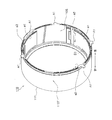
- FIG. 4 is a perspective view of the fixed frame 100.
- the fixed frame 100 includes a fixed frame main body 101 and a zoom gear support portion 102.
- the fixed frame main body 101 is formed in a cylindrical shape, and has an inner peripheral surface 100S and an outer peripheral surface 100T.
- the front support portion 102 is provided so as to protrude from the outer peripheral surface 100T.
- the front support unit 102 rotatably supports the front end of the zoom gear 242.
- the front support portion 102 is covered with the front plate 11 and thus is not exposed to the outside of the housing 10 (see FIG. 1). Note that the tooth portion of the zoom gear 242 protrudes inside the fixed frame main body 101.
- the fixed frame 100 has five rectilinear grooves a1 and three cam grooves b1. However, in FIG. 4, three rectilinear grooves a1 and two cam grooves b1 are shown.
- the five rectilinear grooves a1 are formed on the inner peripheral surface 100S along the optical axis direction, and are arranged at appropriate intervals in the circumferential direction.
- the three cam grooves b1 are formed on the inner peripheral surface 100S so as to intersect the optical axis direction, and are arranged at substantially equal pitches in the circumferential direction.
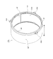
- FIG. 5 is a perspective view of the first rectilinear frame 110.
- the first rectilinear frame 110 includes a rectilinear frame body 111, five rectilinear projections A1, three rectilinear grooves a2, a bayonet groove e1, and a bayonet projection E0.
- the rectilinear frame main body 111 is formed in a cylindrical shape, and has an inner peripheral surface 110S and an outer peripheral surface 110T.
- the five rectilinear protrusions A1 are erected on the rear end portion of the outer peripheral surface 110T.
- the five rectilinear protrusions A1 are engaged with the five rectilinear grooves a1 of the fixed frame 100.
- the three rectilinear grooves a2 are formed on the inner peripheral surface 110S along the optical axis direction.
- the bayonet groove e1 is formed in an arc shape along the circumferential direction at the rear end portion of the inner peripheral surface 110S.
- the bayonet groove e1 intersects with the three rectilinear grooves a2.
- the bayonet protrusion E0 is disposed at the front end portion of the inner peripheral surface 110S.
- the bayonet protrusion E0 is formed in an arc shape along the circumferential direction. In the present embodiment, the bayonet protrusion E0 is divided into a plurality of pieces in the circumferential direction.
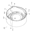
- FIG. 6 is a perspective view of the first rotating frame 210.
- the first rotating frame 210 includes a first rotating frame main body 211 and a gear portion 212.
- the first rotating frame body 211 is formed in a cylindrical shape and has an inner peripheral surface 210S and an outer peripheral surface 210T.
- the gear portion 212 is erected at the rear end portion of the outer peripheral surface 210T, and is formed along the circumferential direction.
- the gear unit 212 When the gear unit 212 is engaged with the zoom gear 242, the first rotating frame 210 is rotated in the circumferential direction by the driving force of the zoom motor 241.
- the gear portion 212 is located behind the rectilinear protrusion A1 of the first rectilinear frame 110.
- the first rotating frame 210 includes three cam followers B1, three bayonet protrusions E1, three cam grooves b2, a bayonet groove e0, three through grooves d, and three rectilinear grooves a3.
- the three cam followers B1 are erected at the rear end portion of the outer peripheral surface 210T, and are arranged at a substantially equal pitch in the circumferential direction.
- Two of the three cam followers B ⁇ b> 1 are disposed at both ends of the gear portion 212.
- the three cam followers B1 are engaged with the three cam grooves b1 of the fixed frame 100.
- the bayonet protrusion E1 is formed along the circumferential direction at the rear end portion of the outer peripheral surface 210T.
- the bayonet protrusion E1 is disposed in front of the gear portion 212.
- the bayonet protrusion E1 is engaged with the bayonet groove e1 of the first rectilinear frame 110.
- the bayonet protrusion E1 and the bayonet groove e1 constitute a bayonet mechanism for rotatably engaging the first rotating frame 210 with the first rectilinear frame 110.
- the three cam grooves b2 penetrate the first rotating frame main body 211 from the inner peripheral surface 210S to the outer peripheral surface 210T.
- the three cam grooves b2 are arranged at a substantially equal pitch in the circumferential direction.
- the bayonet groove e0 is formed at the front end portion of the outer peripheral surface 210T.
- the bayonet groove e0 is formed in an arc shape along the circumferential direction.
- the bayonet groove e0 intersects with the three cam grooves b2.
- a bayonet protrusion E0 is engaged with the bayonet groove e0.
- the three through grooves d penetrate the first rotating frame main body 211 from the inner peripheral surface 210S to the outer peripheral surface 210T.
- the three through grooves d are arranged at a substantially equal pitch in the circumferential direction.
- the three through grooves d function as a part of a cam mechanism for driving the third rectilinear frame 130.
- the three cam grooves b2 and the three through grooves d are alternately arranged in the circumferential direction.
- the three rectilinear grooves a3 are formed along the optical axis direction on the inner peripheral surface 210S. Two of the three rectilinear grooves a3 are close to each other, and the other one is formed 120 ° to 180 ° apart.
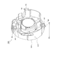
- FIG. 7 is a perspective view of the second rectilinear frame 120.
- the second rectilinear frame 120 includes a rectilinear frame main body 121, and the second rectilinear frame 120 includes three rectilinear cam followers AB2, three rectilinear grooves a4, and a bayonet groove e2.
- the rectilinear frame main body 121 is formed in a cylindrical shape, and has an inner peripheral surface 120S and an outer peripheral surface 120T.
- the three rectilinear cam followers AB2 are erected at the rear end portion of the outer peripheral surface 120T, and are arranged at substantially equal pitches in the circumferential direction.
- the three rectilinear cam followers AB2 are engaged with the three cam grooves b2 of the first rotating frame 210.
- the three rectilinear cam followers AB2 are inserted into the three cam grooves b2 and engaged with the three rectilinear grooves a2 of the first rectilinear frame 110.
- the three rectilinear grooves a4 are formed on the inner peripheral surface 120S along the optical axis direction.
- the three rectilinear grooves a4 are arranged at a substantially equal pitch in the circumferential direction.
- the bayonet groove e2 is formed at the rear end portion of the inner peripheral surface 120S along the circumferential direction.
- the bayonet groove e2 intersects with the three rectilinear grooves a4.
- FIG. 8 is a perspective view of the second rotating frame 220.
- the second rotating frame 220 includes a second rotating frame main body 221, three rectilinear protrusions A3, three bayonet protrusions E2, two bayonet grooves e3, three cam grooves b3, and three cam grooves. b4 and three cam grooves b5. However, in FIG. 8, two cam grooves b3, cam grooves b4, and cam grooves b5 are shown.
- the second rotary frame main body 221 is formed in a cylindrical shape and has an inner peripheral surface 220S and an outer peripheral surface 220T.
- the three rectilinear protrusions A3 are erected at the rear end portion of the outer peripheral surface 220T, and two of the three rectilinear protrusions A3 are close to each other in the circumferential direction, and the other one is the two adjacent rectilinear protrusions A3 to 120. Formed apart by more than °.
- the three rectilinear protrusions A3 are engaged with the three rectilinear grooves a3 of the first rotating frame 210.
- the three bayonet protrusions E2 are formed along the circumferential direction at the rear end portion of the outer peripheral surface 220T.
- the three bayonet protrusions E2 are disposed in front of the three rectilinear protrusions A3.
- the bayonet protrusion E2 is engaged with the bayonet groove e2 of the second rectilinear frame 120.
- the bayonet protrusion E2 and the bayonet groove e2 constitute a bayonet mechanism for rotatably engaging the second rotary frame 220 with the second rectilinear frame 120.
- the two bayonet grooves e3 are formed in the substantially central portion of the inner peripheral surface 220S along the circumferential direction.
- the two bayonet grooves e3 are formed in parallel to each other.
- the two bayonet grooves e3 intersect with the cam groove b4 and the cam groove b5.
- the three cam grooves b3 are formed on the outer peripheral surface 220T so as to intersect the optical axis direction, and are arranged at substantially equal pitches in the circumferential direction.
- the cam groove b4 and the cam groove b5 are formed on the inner peripheral surface 220S.
- the cam groove b4 and the cam groove b5 intersect each other.
- FIG. 9 is a perspective view of the third rectilinear frame 130.
- the third rectilinear frame 130 includes a rectilinear frame main body 131, a flange portion 132, and three through protrusions AD.
- the rectilinear frame main body 131 is formed in a cylindrical shape, and has an inner peripheral surface 130S and an outer peripheral surface 130T.
- the flange portion 132 is formed in an annular shape and is erected on the rear end portion of the outer peripheral surface 130T.
- the three penetrating protrusions AD are erected on the outer surface of the flange portion 132 and are arranged at a substantially equal pitch in the circumferential direction.
- the three through protrusions AD are inserted into the three through grooves d of the first rotary frame 210 and are engaged with the three rectilinear grooves a2 of the first rectilinear frame 110.
- the three through protrusions AD function as a cam mechanism for driving the third rectilinear frame 130 together with the three through grooves d.
- the third rectilinear frame 130 includes two bayonet protrusions E3, three rectilinear grooves a5, and three rectilinear grooves a6. However, in FIG. 9, only two bayonet protrusions E3 are shown.
- the two bayonet protrusions E3 are formed along the circumferential direction at a substantially central portion of the outer peripheral surface 130T.
- the two bayonet protrusions E3 are formed in parallel to each other.
- the two bayonet protrusions E3 are engaged with the two bayonet grooves e3 of the second rotation frame 220.
- the bayonet protrusion E3 and the bayonet groove e3 constitute a bayonet mechanism for rotatably engaging the third rectilinear frame 130 with the second rotation frame 220.
- the three rectilinear grooves a5 penetrate the rectilinear frame main body 131 from the inner peripheral surface 130S to the outer peripheral surface 130T.
- the three rectilinear grooves a5 extend along the optical axis direction and are arranged at substantially equal pitches in the circumferential direction.
- the three rectilinear grooves a6 penetrate the rectilinear frame main body 131 from the inner peripheral surface 130S to the outer peripheral surface 130T.
- the three rectilinear grooves a6 extend along the optical axis direction and are arranged at substantially equal pitches in the circumferential direction.
- the three rectilinear grooves a5 and the three rectilinear grooves a6 are alternately arranged in the circumferential direction.
- FIG. 10 is a perspective view of the first lens group frame 310.
- the first lens group frame 310 includes a first lens group frame main body 311, three rectilinear projections A4, and three cam projections B3.
- the first lens group frame body 311 is formed in a cylindrical shape, and has an inner peripheral surface 310S and an outer peripheral surface 310T.
- the first lens group frame main body 311 is formed with three projecting portions 311a projecting rearward.
- the three rectilinear protrusions A4 are erected on the outer peripheral surface 310T of the protruding portion 311a, and are arranged at a substantially equal pitch in the circumferential direction.
- the three rectilinear protrusions A4 are engaged with the three rectilinear grooves a4 of the second rectilinear frame 120.
- the three cam protrusions B3 are erected on the inner peripheral surface 310S of the protruding portion 311a, and are arranged at a substantially equal pitch in the circumferential direction.
- the three cam protrusions B3 are engaged with the three cam grooves b3 of the second rotating frame 220.
- the three rectilinear protrusions A4 and the three cam protrusions B3 are disposed substantially opposite to each other with the protrusion 311a interposed therebetween.
- FIG. 11 is a perspective view of the second lens group frame 320.
- the second lens group frame 320 includes a second lens group frame main body 321, three rectilinear projections A5, and three cam projections B4.
- the second lens group frame main body 321 is formed in a cup shape and has an outer peripheral surface 320T.
- the three rectilinear protrusions A5 are formed on the rear end portion of the outer peripheral surface 320T, and are arranged at a substantially equal pitch in the circumferential direction.
- the three rectilinear protrusions A5 are engaged with the three rectilinear grooves a5 of the third rectilinear frame 130.
- the three cam protrusions B4 are formed on the three rectilinear protrusions A5.
- the three cam protrusions B4 are engaged with the three cam grooves b4 of the second rotating frame 220.
- FIG. 12 shows a state in which the third lens group frame 330 is housed inside the shutter frame 335.
- the configuration of the third lens group frame 330 will be described with reference to FIG.
- the third lens group frame 330 that is, an OIS (Optical Image Stabilizer) unit mainly includes an OIS frame 400, a retractable lens frame 401, and a third lens group L3 for image blur correction.
- OIS Optical Image Stabilizer
- the OIS frame 400 is attached to the shutter frame 335. Specifically, the OIS frame 400 is movable in a plane perpendicular to the optical axis. More specifically, a magnet (not shown) is fixed to the OIS frame 400, and a coil (not shown) is fixed to the shutter frame 335 at a position facing the magnet. In this state, when electric power is supplied from a camera circuit (not shown) to the coil of the shutter frame, a current flows through the coil to generate a magnetic field. The magnetic field drives the magnet of the OIS frame 400, and the driving force moves the OIS frame 400 in a plane perpendicular to the optical axis.
- the retraction lens frame 401 is held by the OIS frame 400 so as to be movable around a retraction axis substantially parallel to the optical axis.
- the retractable lens frame 401 moves from a correctable position (first posture) where the third lens unit L3 can perform image blur correction to a retracted position (second posture) where the third lens unit L3 is retracted from the optical axis. Its position can be changed.
- the retractable lens frame 401 holds a third lens unit L3 including at least one lens.
- the shutter frame 335 includes a shutter frame main body 336, three rectilinear protrusions A6, and three cam protrusions B5.
- the shutter frame body 336 is formed in a cylindrical shape and has an outer peripheral surface 335T.
- the three rectilinear protrusions A6 are formed on the outer peripheral surface 335T, and are arranged at a substantially equal pitch in the circumferential direction.
- the three rectilinear protrusions A6 are engaged with the three rectilinear grooves a6 of the third rectilinear frame 130.
- the three cam protrusions B5 are erected on the front end portions of the three rectilinear protrusions A6.
- the three cam protrusions B5 are engaged with the three cam grooves b5 of the second rotating frame 220.
- FIGS. 13 to 15 are sectional views of the lens barrel 20.
- FIGS. 13 to 15 are schematic diagrams in which a plurality of cut surfaces passing through the optical axis AX are combined. 13 illustrates the retracted state of the lens barrel 20, FIG. 14 illustrates the wide state of the lens barrel 20, and FIG. 15 illustrates the tele state of the lens barrel 20.
- the shootable state of the digital camera 1 means the state of the lens barrel 20 from the wide state to the tele state.
- the gear portion 212 of the first rotating frame 210 is meshed with the zoom gear 242 (not shown).
- the cam follower B1 of the first rotating frame 210 is engaged with the cam groove b1 of the fixed frame 100. Therefore, the first rotating frame 210 can move in the optical axis direction while rotating in the circumferential direction by the driving force of the zoom motor 241.
- the rectilinear projection A1 of the first rectilinear frame 110 is engaged with the rectilinear groove a1 of the fixed frame 100.
- the bayonet protrusion E1 of the first rotating frame 210 is engaged with the bayonet groove e1 of the first rectilinear frame 110. Therefore, the first rectilinear frame 110 can go straight in the optical axis direction together with the first rotating frame 210.
- the rectilinear cam follower AB2 of the second rectilinear frame 120 is inserted into the cam groove b2 of the first rotating frame 210 and is engaged with the rectilinear groove a2 of the first rectilinear frame 110. Therefore, the second rectilinear frame 120 can go straight in the optical axis direction according to the rotation of the first rotating frame 210.
- the rectilinear protrusion A3 of the second rotating frame 220 is engaged with the rectilinear groove a3 of the first rotating frame 210.
- the bayonet protrusion E ⁇ b> 2 of the second rotating frame 220 is engaged with the bayonet groove e ⁇ b> 2 of the second rectilinear frame 120. Therefore, the second rotating frame 220 is movable in the optical axis direction together with the second rectilinear frame 120 while rotating in the circumferential direction together with the first rotating frame 210.
- the through protrusion AD of the third rectilinear frame 130 is inserted into the through groove d of the first rotating frame 210 and is engaged with the rectilinear groove a2 of the first rectilinear frame 110. Further, the bayonet protrusion E3 of the third rectilinear frame 130 is engaged with the bayonet groove e3 of the second rotary frame 220. Therefore, the third rectilinear frame 130 can go straight in the optical axis direction according to the rotation of the second rotating frame 220.
- the rectilinear projection A4 of the first lens group frame 310 is engaged with the rectilinear groove a4 of the second rectilinear frame 120.
- the cam protrusion B3 of the first lens group frame 310 is engaged with the cam groove b3 of the second rotation frame 220. Therefore, the first lens group frame 310 can go straight in the optical axis direction according to the rotation of the second rotation frame 220.
- the rectilinear protrusion A5 of the second lens group frame 320 is engaged with the rectilinear groove a5 of the third rectilinear frame 130. Further, the cam protrusion B4 of the second lens group frame 320 is engaged with the cam groove b4 of the second rotation frame 220. Therefore, the second lens group frame 320 can go straight in the optical axis direction according to the rotation of the second rotation frame 220.
- the rectilinear protrusion A6 of the shutter frame 335 is engaged with the rectilinear groove a6 of the third rectilinear frame 130. Further, the cam projection B5 of the shutter frame 335 is engaged with the cam groove b5 of the second rotation frame 220. Therefore, the shutter frame 335 can go straight in the optical axis direction in accordance with the rotation of the second rotation frame 220.
- a third lens group frame 330 is attached to the shutter frame 335, and when the shutter frame 335 moves straight in the optical axis direction with respect to the third rectilinear frame 130, the retractable lens frame 401 of the third lens group frame 330 is It is rotated by a retracting mechanism (not shown).
- a retracting mechanism not shown
- the retractable lens frame 401 moves from the retracted position to the correctable position.
- the retractable lens frame 401 moves from the correctable position to the retracted position.
- the third lens unit L3 is movable in a plane perpendicular to the optical axis. That is, in this state, image blur correction can be performed.
- the first to third rectilinear frames 110 to 130 and the lens group frames 310, 320, and 335 move straight by the rotation of the first rotating frame 210 and the second rotating frame 220 by the driving force of the zoom motor 241. It has been realized.
- FIG. 16 is an enlarged view of a region R in FIG.
- the digital camera 1 includes a first light shielding member 510 and a second light shielding member 520.
- the first light shielding member 510 is an annular member disposed between the first moving lens barrel portion 21 and the second moving lens barrel portion 22.
- the first light blocking member 510 prevents external light from entering the inside through the gap between the first movable lens barrel portion 21 and the second movable lens barrel portion 22.
- the first light shielding member 510 includes a first rotating frame 210, a front covering portion 301a that covers the front of the first rotating frame 210 among the first decorative frame 301 that is bonded and fixed to the first rectilinear frame 110, and It is arranged between.
- the first light shielding member 510 is sandwiched between the front end surface 210R of the first rotating frame 210 and the rear surface 301R of the front covering portion 301a. Further, on the outer side in the radial direction of the front end surface 210R of the first rotary frame 210, a side surface 210U is provided to stand in the optical axis direction. For this reason, the position of the first light shielding member 510 in the radial direction is restricted.
- the first light shielding member 510 is fitted on the outer periphery of the second decorative frame 302.
- the first light shielding member 510 when the second decorative frame 302 is extended, the first light shielding member 510 is brought into contact with the rear surface 301R of the front covering portion 301a due to contact friction with the outer periphery of the second decorative frame 302, so that the second decorative frame 302 is brought into contact. Is stored in contact with the front end surface 210 ⁇ / b> R of the first rotating frame 210. That is, the first light-shielding member 510 is always in contact with the outer periphery of the second decorative frame 302 or intermittently in contact with the outer surface of the front covering portion 301a while maintaining a small gap, and the front end surface 210R of the first rotating frame 210. Move slightly between the gaps. Therefore, the first light blocking member 510 prevents external light from entering the inside through the gap between the first moving lens barrel portion 21 and the second moving lens barrel portion 22.
- the second light shielding member 520 is an annular member disposed between the second movable lens barrel portion 22 and the third movable lens barrel portion 23.
- the second light shielding member 520 suppresses external light from entering through the gap between the second moving barrel portion 22 and the third moving barrel portion 23.
- the second light shielding member 520 includes a second rectilinear frame 120 and a front covering portion 302a that covers the front of the second rectilinear frame 120 of the second decorative frame 302 that is bonded and fixed to the second rectilinear frame 120; It is arranged between. That is, the second light shielding member 520 is disposed between the front end surface 120R of the second rectilinear frame 120 and the rear surface 302R of the front covering portion 302a.
- the second light shielding member 520 is fitted on the outer periphery of the third decorative frame 303, and when the third decorative frame 303 is extended, the second light shielding member 520 is brought into contact with the outer periphery of the third decorative frame 303.
- the third decorative frame 303 When the third decorative frame 303 is housed, it is brought into contact with the front end surface 120R of the second rectilinear frame 120.
- FIG. 17 is an enlarged cross-sectional view of the first light shielding member 510. Since the second light shielding member 520 has the same configuration as the first light shielding member 510, only the configuration of the first light shielding member 510 will be described. As shown in FIG. 17, the first light shielding member 510 includes a light shielding layer 501, a support layer 502, and an elastic layer 503.
- the light shielding layer 501 is configured by forming a light shielding layer on the surface of a resin film, for example.
- the light shielding layer 501 is disposed so as to face the front end face 210 ⁇ / b> R of the first rotation frame 210.
- the inner diameter of the light shielding layer 501 is substantially the same as or smaller than the outer diameter of the second decorative frame 302.
- the support layer 502 is made of a material having a relatively high rigidity, that is, a hard material having a large elastic modulus, such as a PET (Poly-Ethylene-Terephthalate) resin, in order to ensure the rigidity of the light shielding member 520 as a whole.
- the PET layer 502 supports the light shielding layer 501 so that the light shielding layer 501 is not bent.
- the support layer 502 is attached to the front surface 501R side of the light shielding layer 501 via the first adhesive layer 500a.
- the elastic layer 503 is made of a material having relatively low rigidity, that is, soft and low elastic modulus, such as neoprene rubber.
- the elastic layer 503 is attached to the front surface 502R side of the support layer 502 via the second adhesive layer 500b.
- the elastic layer 503 is sandwiched between the support layer 502 and the front covering portion 301a of the first decorative frame 301 (see FIG. 16). Therefore, the elastic layer 503 contacts the rear surface 301R of the front covering portion 301a when the second decorative frame 302 is drawn out.
- the conventional light shielding member is an annular member, and a light shielding layer such as a rubber material, an adhesive layer, and a support layer such as a PET resin are formed in layers from the rear side in the optical axis direction.
- the light-shielding member is in contact with each other when the cylinder fitted to the inner diameter moves, and thus vibrates or swings when the moving direction is reversed.
- the light-shielding member May come into contact with surrounding members and generate abnormal noise.
- a support layer such as a PET resin comes into contact with surrounding members, a large abnormal noise may occur.
- the inventor considered reduction of vibration of the light shielding member or reduction of impact force of the contact portion in order to suppress abnormal noise.
- the light shielding member should be made of a viscous material having a damper effect.
- the light shielding member may be made of a soft material, that is, a material having a small elastic coefficient. Since the support layer is a material having a relatively small viscosity and a large elastic coefficient, the damper effect for suppressing vibration is small and the impact force is difficult to suppress. For this reason, when a light shielding member having a conventional configuration is used, abnormal noise may occur due to vibration or swinging of the light shielding member during zooming.
- the support layer is made of a material having a damper effect viscosity and softness, that is, a low elastic modulus, similar to the light shielding layer, vibration or swinging of the light shielding member can be suppressed.
- the elastic layer 503 of the first light shielding member 510 is disposed between the rear surface 301R of the front covering portion 301a and the support layer 502.
- the light shielding layer 501 and the elastic layer 503 are bonded to the front and back of the support layer 502 made of a material having a large elastic coefficient.
- the light shielding layer 501 and the elastic layer 503 are both made of a material having viscosity and a small elastic coefficient. Therefore, the first light shielding member 510 has a damper effect and can suppress the impact force of the contact portion. Therefore, the first light shielding member 510 can suppress the generation of noise due to the support layer 502 rubbing against the rear surface 301R of the front covering portion 301a.
- the support layer 502 is made of a material having a large elastic coefficient
- the entire first light shielding member 510 can maintain a state having a large elastic coefficient. Accordingly, it is possible to prevent the first light blocking member 510 from protruding outside the gap between the first decorative frame 301 and the second decorative frame 302 during zooming.
- the elastic layer 503 of the first light shielding member 510 may not be attached to the support layer 502 and may be attached to the rear surface 301R of the front covering portion 301a. However, if the elastic layer 503 and the light shielding layer 501 are attached to both surfaces of the support layer 502, the vibration or swinging of the entire first light shielding member 510 can be suppressed by the damper effect of the elastic layer 503. ,preferable.
- the light shielding layer 501 may be made of a material having a relatively low rigidity such as neoprene rubber, that is, a soft material having a small elastic coefficient and having a light shielding property.
- a material having a viscosity having a damper effect and a small elastic coefficient is suitable.
- a material having an elastic coefficient of about 0.001 to 0.2 Gpa such as rubber, foamed polyurethane, or foamed polymer can be used.
- a material having a larger elastic coefficient than the materials of the light shielding layer 501 and the elastic layer 503 is suitable.
- a material having an elastic modulus of about 1.0 to 500.0 GPa such as PET, PC (Polycarbonate), PS (Polystyrene), nylon, acrylic, polyimide, aluminum alloy, iron, stainless steel, etc. Can be used.
- the lens barrel The first frame; A cylindrical second frame disposed outside the first frame; A cylindrical third frame that is disposed outside the second frame and has a front covering portion that covers the front of the second frame; An annular light shielding member disposed between the front end surface of the second frame and the opposing surface of the front covering portion facing the front end surface, and attached to the outer periphery of the first frame; With The light shielding member is A light shielding layer facing the front end surface of the second frame; A support layer attached to the opposite surface side of the light shielding layer; An elastic layer disposed between the support layer and the facing surface; Including The light shielding layer and the elastic layer have a smaller elastic coefficient than the support layer.
- the third rectilinear frame 130 is inserted from the rear of the second rotating frame 220. Subsequently, the third rectilinear frame 130 is rotated in the circumferential direction to be in the tele state. Next, the second lens group frame 320 is inserted from the rear of the third rectilinear frame 130. Next, the retractable lens frame 401 is inserted from the front of the OIS frame 400, and the OIS frame 400 is rotatably attached to the retractable lens frame 401.
- the OIS frame 400 is inserted from the front of the shutter frame 335.
- the shutter frame 335 is inserted from the rear of the third rectilinear frame 130.
- the second lens group frame 320 is rotated in the circumferential direction to be in a retracted state.
- the second rotating frame 220 is inserted from the rear of the first lens group frame 310.
- the second rectilinear frame 120 is covered from the front of the first lens group frame 310.
- first rotating frame 210 is inserted from the rear of the first rectilinear frame 110.
- second rectilinear frame 120 is inserted from the rear of the first rotating frame 210.
- first rectilinear frame 110 is inserted from the rear of the fixed frame 100.
- each frame is rotated to be in the retracted state.
- the lens barrel 20 includes a cylindrical fixed frame 100, a cylindrical first rectilinear frame 110, a cylindrical first rotating frame 210, a cylindrical second rectilinear frame 120, and a second rotation.
- a frame 220 and a third rectilinear frame 130 are provided.
- the fixed frame 100 has a rectilinear groove a1 (an example of a first rectilinear groove) and a cam groove b1 (an example of a first cam groove) formed on the inner peripheral surface 100S.
- the first rectilinear frame 110 is disposed on the radially inner side of the fixed frame 100.
- the first rectilinear frame 110 is formed on the outer circumferential surface 110T, and the rectilinear projection A1 (an example of the first rectilinear projection) engaged with the rectilinear groove a1, and the rectilinear groove a2 (second rectilinear advance) formed on the inner peripheral surface 110S.
- An example of a groove An example of a groove.
- the first rotating frame 210 is disposed on the radially inner side of the first rectilinear frame 110.
- the first rotating frame 210 is formed on the outer peripheral surface 210T and penetrates the first rotating frame main body 211 from the inner peripheral surface 210S to the outer peripheral surface 210T, and a cam follower B1 (an example of a first cam follower) that is engaged with the cam groove b1.
- Cam groove b2 (an example of a second cam groove), a through groove d that penetrates the first rotary frame main body 211 from the inner peripheral surface 210S to the outer peripheral surface 210T, and a rectilinear groove b3 (a first groove formed on the inner peripheral surface 210S) An example of three straight grooves).
- the second rectilinear frame 120 is disposed on the radially inner side of the first rotating frame 210.
- the second rotary frame 220 is disposed on the radially inner side of the second rectilinear frame 120.
- the second rotary frame 220 is engaged with the second rectilinear frame 120 by a bayonet mechanism (an example of the bayonet protrusion E2, the bayonet groove e2, and the first bayonet mechanism).
- the second rotary frame 220 has a rectilinear projection A3 (an example of a second rectilinear projection) that is engaged with the rectilinear groove a3 on the outer peripheral surface 220T.
- the third rectilinear frame 130 is disposed on the radially inner side of the second rotating frame 220.
- the third rectilinear frame 130 is engaged with the second rotating frame 220 by a bayonet mechanism (an example of a bayonet protrusion E3 and a bayonet groove e3, a second bayonet mechanism).
- the second rectilinear frame 120 is formed on the outer peripheral surface 120T and includes a rectilinear cam follower AB2 (an example of a rectilinear cam follower) that is engaged with the rectilinear groove a2 of the first rectilinear frame 110 via the cam groove b2 of the first rotating frame 210.
- a rectilinear cam follower AB2 an example of a rectilinear cam follower
- the third rectilinear frame 130 is formed on the outer peripheral surface 130T, and is a through protrusion AD (an example of a third rectilinear protrusion) that is engaged with the rectilinear groove a2 of the first rectilinear frame 110 via the through groove d of the first rotating frame 210. ).
- the cam follower B1 of the first rotating frame 210 is located behind the first rectilinear protrusion A1 of the first rectilinear frame 110 in the optical axis direction. Can be placed.
- the overall length of the lens barrel 20 in the optical axis direction is not increased, and the cam follower B1 of the first rotating frame 210 is engaged.
- the wall of the front end portion in the optical axis direction of the first rectilinear groove a1 of the fixed frame 100 to be combined can be thickened. Accordingly, the lens barrel 20 can be made compact while maintaining the amount of movement of the first rotating frame 210 relative to the fixed frame 100, that is, maintaining the zoom magnification, and the strength against external force such as dropping can be improved.
- each of the second rectilinear frame 120 and the third rectilinear frame 130 is linearly guided independently of the first rectilinear frame 110.
- the rotation angle of the second rotary frame 220 can be increased as compared with the case where the relative rotation of each other is suppressed by locking the second rectilinear frame 120 and the third rectilinear frame 130 in the optical axis direction.
- the zoom magnification can be further increased in the compact lens barrel 20.
- the through groove d and the through protrusion AD are engaged by a cam mechanism. Accordingly, since the external force applied to the third rectilinear frame 130 can be received by the through protrusion AD engaged with the through groove d, the connection between the third rectilinear frame 130 and the second rotary frame 220 can be strengthened. it can.
- the through groove d and the through protrusion AD are engaged by the cam mechanism, but the present invention is not limited to this.
- the through protrusion AD is spaced from the inner surface of the through groove d, and the through protrusion AD need only be inserted through the through groove d.
- the second linear frame 120 has the rectilinear cam follower AB2.
- the third linear frame 130 may have the rectilinear cam follower AB2 instead of the second linear frame 120.
- the second linear frame 120 may have the penetrating protrusion AD instead of the third linear frame 130.
- the lens barrel 20 is a three-stage retractable type, but is not limited thereto.
- the lens barrel 20 may be a retractable type having four or more stages.
- the cam groove b is formed in one of the two frames and the cam projection B is formed in the other frame, but the present invention is not limited to this.
- the cam projection B may be formed on one of the two frames, and the cam groove b may be formed on the other frame.
- the cam groove b and the cam protrusion B may be formed in each of the two frames.
- the rectilinear groove a is formed in one of the two frames and the rectilinear projection A is formed in the other frame, but the present invention is not limited to this.
- the rectilinear protrusion A may be formed on one of the two frames, and the rectilinear groove a may be formed on the other frame.
- channel a and the rectilinear advance protrusion A may be formed in each of two frames.
- the bayonet groove e is formed in one of the two frames and the bayonet protrusion E is formed in the other frame, but this is not restrictive.
- the bayonet protrusion E may be formed in one of the two frames, and the bayonet groove e may be formed in the other frame.
- channel e and the bayonet protrusion E may be formed in each of two frames.
- the third lens group frame 330 is retracted to the side of the second lens group frame 320 in the retracted state, but the present invention is not limited to this.
- the third lens group frame 330 may be disposed behind the second lens group frame 320 in the retracted state.
- a lens barrel that can be made compact can be provided, and can be applied to, for example, a camera, a mobile phone with a camera, a portable terminal with a camera, and the like.
Landscapes
- Physics & Mathematics (AREA)
- Engineering & Computer Science (AREA)
- General Engineering & Computer Science (AREA)
- General Physics & Mathematics (AREA)
- Optics & Photonics (AREA)
- Lens Barrels (AREA)
- Structure And Mechanism Of Cameras (AREA)
- Blocking Light For Cameras (AREA)
Abstract
L'invention concerne un barillet de lentilles (20) dans lequel un second cadre rectiligne (120) comprend un suiveur de came rectiligne (AB2) inséré dans une gorge rectiligne (a2) via une gorge de came (b2) d'un premier cadre rotatif (210) sur une surface périphérique externe (120T). Un troisième cadre rectiligne (130) comprend une protubérance pénétrante (AD) insérée dans la gorge rectiligne (a2) via une gorge de pénétration (d) sur une surface périphérique externe (130T).
Priority Applications (1)
| Application Number | Priority Date | Filing Date | Title |
|---|---|---|---|
| JP2013552337A JP5958773B2 (ja) | 2012-01-06 | 2012-03-16 | レンズ鏡筒 |
Applications Claiming Priority (2)
| Application Number | Priority Date | Filing Date | Title |
|---|---|---|---|
| JP2012001687 | 2012-01-06 | ||
| JP2012-001687 | 2012-01-06 |
Publications (1)
| Publication Number | Publication Date |
|---|---|
| WO2013102959A1 true WO2013102959A1 (fr) | 2013-07-11 |
Family
ID=48745037
Family Applications (1)
| Application Number | Title | Priority Date | Filing Date |
|---|---|---|---|
| PCT/JP2012/001877 Ceased WO2013102959A1 (fr) | 2012-01-06 | 2012-03-16 | Barillet de lentilles |
Country Status (2)
| Country | Link |
|---|---|
| JP (1) | JP5958773B2 (fr) |
| WO (1) | WO2013102959A1 (fr) |
Citations (3)
| Publication number | Priority date | Publication date | Assignee | Title |
|---|---|---|---|---|
| JPH0637811Y2 (ja) * | 1989-07-24 | 1994-10-05 | 株式会社クラレ | モツプ基布 |
| JP2010039286A (ja) * | 2008-08-06 | 2010-02-18 | Canon Inc | 撮像装置 |
| JP2011215279A (ja) * | 2010-03-31 | 2011-10-27 | Canon Inc | レンズ鏡筒及び撮像装置 |
Family Cites Families (4)
| Publication number | Priority date | Publication date | Assignee | Title |
|---|---|---|---|---|
| JP3406671B2 (ja) * | 1994-02-10 | 2003-05-12 | ペンタックス株式会社 | レンズ鏡筒の遮光装置 |
| JPH08146501A (ja) * | 1994-11-25 | 1996-06-07 | Canon Inc | シール装置 |
| JP4129283B2 (ja) * | 1997-04-18 | 2008-08-06 | オリンパス株式会社 | レンズ鏡筒 |
| JP2011145373A (ja) * | 2010-01-13 | 2011-07-28 | Panasonic Corp | レンズ鏡筒およびそれを用いた撮像装置 |
-
2012
- 2012-03-16 JP JP2013552337A patent/JP5958773B2/ja active Active
- 2012-03-16 WO PCT/JP2012/001877 patent/WO2013102959A1/fr not_active Ceased
Patent Citations (3)
| Publication number | Priority date | Publication date | Assignee | Title |
|---|---|---|---|---|
| JPH0637811Y2 (ja) * | 1989-07-24 | 1994-10-05 | 株式会社クラレ | モツプ基布 |
| JP2010039286A (ja) * | 2008-08-06 | 2010-02-18 | Canon Inc | 撮像装置 |
| JP2011215279A (ja) * | 2010-03-31 | 2011-10-27 | Canon Inc | レンズ鏡筒及び撮像装置 |
Also Published As
| Publication number | Publication date |
|---|---|
| JPWO2013102959A1 (ja) | 2015-05-11 |
| JP5958773B2 (ja) | 2016-08-02 |
Similar Documents
| Publication | Publication Date | Title |
|---|---|---|
| JP6524414B2 (ja) | レンズ鏡筒 | |
| JP5105186B2 (ja) | レンズ鏡筒および撮像装置 | |
| JP5448630B2 (ja) | レンズ鏡筒及びそれを有する光学機器 | |
| CN102486568A (zh) | 镜筒装置和成像设备 | |
| WO2013114907A1 (fr) | Barillet d'objectif | |
| JP6020938B2 (ja) | レンズ鏡筒 | |
| JP6099924B2 (ja) | 光学機器およびそれを備えた撮像装置 | |
| JP5958773B2 (ja) | レンズ鏡筒 | |
| JP6135933B2 (ja) | レンズ鏡筒 | |
| WO2013114905A1 (fr) | Barillet d'objectif | |
| JP6435518B2 (ja) | レンズ鏡筒 | |
| JP5854255B2 (ja) | レンズ鏡胴、撮像装置および情報装置 | |
| JP2011215279A (ja) | レンズ鏡筒及び撮像装置 | |
| JP6057258B2 (ja) | レンズ鏡筒 | |
| JP6229163B2 (ja) | レンズ鏡筒 | |
| JP6078926B2 (ja) | レンズ鏡筒 | |
| JP4710340B2 (ja) | レンズ鏡筒 | |
| US9465188B2 (en) | Lens barrel | |
| JP6108277B2 (ja) | レンズ鏡筒 | |
| JP2015079016A (ja) | レンズ鏡筒 | |
| JP2010197719A (ja) | レンズ駆動装置及び撮像装置 | |
| JP2014145881A (ja) | 監視カメラ | |
| JP2011227328A (ja) | レンズ鏡筒及び撮影装置 | |
| JP6493785B2 (ja) | レンズ鏡筒及び撮像装置 | |
| JP2012108551A (ja) | レンズ鏡筒用支持枠、レンズ保持構造、レンズ鏡筒およびカメラ |
Legal Events
| Date | Code | Title | Description |
|---|---|---|---|
| 121 | Ep: the epo has been informed by wipo that ep was designated in this application |
Ref document number: 12864129 Country of ref document: EP Kind code of ref document: A1 |
|
| ENP | Entry into the national phase |
Ref document number: 2013552337 Country of ref document: JP Kind code of ref document: A |
|
| NENP | Non-entry into the national phase |
Ref country code: DE |
|
| 122 | Ep: pct application non-entry in european phase |
Ref document number: 12864129 Country of ref document: EP Kind code of ref document: A1 |