WO2013103131A1 - パネル支持架台 - Google Patents
パネル支持架台 Download PDFInfo
- Publication number
- WO2013103131A1 WO2013103131A1 PCT/JP2012/083987 JP2012083987W WO2013103131A1 WO 2013103131 A1 WO2013103131 A1 WO 2013103131A1 JP 2012083987 W JP2012083987 W JP 2012083987W WO 2013103131 A1 WO2013103131 A1 WO 2013103131A1
- Authority
- WO
- WIPO (PCT)
- Prior art keywords
- panel
- support
- plate member
- plate
- column
- Prior art date
- Legal status (The legal status is an assumption and is not a legal conclusion. Google has not performed a legal analysis and makes no representation as to the accuracy of the status listed.)
- Ceased
Links
Images





Classifications
-
- H—ELECTRICITY
- H02—GENERATION; CONVERSION OR DISTRIBUTION OF ELECTRIC POWER
- H02S—GENERATION OF ELECTRIC POWER BY CONVERSION OF INFRARED RADIATION, VISIBLE LIGHT OR ULTRAVIOLET LIGHT, e.g. USING PHOTOVOLTAIC [PV] MODULES
- H02S20/00—Supporting structures for PV modules
-
- F—MECHANICAL ENGINEERING; LIGHTING; HEATING; WEAPONS; BLASTING
- F24—HEATING; RANGES; VENTILATING
- F24S—SOLAR HEAT COLLECTORS; SOLAR HEAT SYSTEMS
- F24S25/00—Arrangement of stationary mountings or supports for solar heat collector modules
- F24S25/10—Arrangement of stationary mountings or supports for solar heat collector modules extending in directions away from a supporting surface
- F24S25/12—Arrangement of stationary mountings or supports for solar heat collector modules extending in directions away from a supporting surface using posts in combination with upper profiles
-
- F—MECHANICAL ENGINEERING; LIGHTING; HEATING; WEAPONS; BLASTING
- F24—HEATING; RANGES; VENTILATING
- F24S—SOLAR HEAT COLLECTORS; SOLAR HEAT SYSTEMS
- F24S25/00—Arrangement of stationary mountings or supports for solar heat collector modules
- F24S25/60—Fixation means, e.g. fasteners, specially adapted for supporting solar heat collector modules
- F24S25/65—Fixation means, e.g. fasteners, specially adapted for supporting solar heat collector modules for coupling adjacent supporting elements, e.g. for connecting profiles together
-
- F—MECHANICAL ENGINEERING; LIGHTING; HEATING; WEAPONS; BLASTING
- F24—HEATING; RANGES; VENTILATING
- F24S—SOLAR HEAT COLLECTORS; SOLAR HEAT SYSTEMS
- F24S25/00—Arrangement of stationary mountings or supports for solar heat collector modules
- F24S25/70—Arrangement of stationary mountings or supports for solar heat collector modules with means for adjusting the final position or orientation of supporting elements in relation to each other or to a mounting surface; with means for compensating mounting tolerances
-
- Y—GENERAL TAGGING OF NEW TECHNOLOGICAL DEVELOPMENTS; GENERAL TAGGING OF CROSS-SECTIONAL TECHNOLOGIES SPANNING OVER SEVERAL SECTIONS OF THE IPC; TECHNICAL SUBJECTS COVERED BY FORMER USPC CROSS-REFERENCE ART COLLECTIONS [XRACs] AND DIGESTS
- Y02—TECHNOLOGIES OR APPLICATIONS FOR MITIGATION OR ADAPTATION AGAINST CLIMATE CHANGE
- Y02E—REDUCTION OF GREENHOUSE GAS [GHG] EMISSIONS, RELATED TO ENERGY GENERATION, TRANSMISSION OR DISTRIBUTION
- Y02E10/00—Energy generation through renewable energy sources
- Y02E10/40—Solar thermal energy, e.g. solar towers
- Y02E10/47—Mountings or tracking
-
- Y—GENERAL TAGGING OF NEW TECHNOLOGICAL DEVELOPMENTS; GENERAL TAGGING OF CROSS-SECTIONAL TECHNOLOGIES SPANNING OVER SEVERAL SECTIONS OF THE IPC; TECHNICAL SUBJECTS COVERED BY FORMER USPC CROSS-REFERENCE ART COLLECTIONS [XRACs] AND DIGESTS
- Y02—TECHNOLOGIES OR APPLICATIONS FOR MITIGATION OR ADAPTATION AGAINST CLIMATE CHANGE
- Y02E—REDUCTION OF GREENHOUSE GAS [GHG] EMISSIONS, RELATED TO ENERGY GENERATION, TRANSMISSION OR DISTRIBUTION
- Y02E10/00—Energy generation through renewable energy sources
- Y02E10/50—Photovoltaic [PV] energy
Definitions
- the present invention relates to a panel support frame that is installed on an installation surface while supporting a panel.
- a solar power generation panel also referred to as a solar panel or a solar battery panel
- a stand for supporting the solar power generation panel toward the sun is necessary.
- Patent Document 1 discloses a mounting frame formed in a rectangular frame shape as a frame for supporting a solar battery panel (solar power generation panel), and a mounting beam arranged in parallel at a fixed interval inside the mounting frame. And a pedestal including a support joined to each of the four corners of the mounting frame is disclosed.
- the solar cell panel is mounted in a mounting space formed by the mounting frame and the mounting beam. Since the heights of the support columns are different between the front and the back, the solar cell panel can be supported while being inclined toward the sun.
- the gantry disclosed in Patent Document 1 requires at least four struts, and each of the four struts is provided with a reinforcing member (support diagonal member) for ensuring the bonding strength with the mounting frame. It is necessary to prepare a plurality and connect the support column and the mounting frame with the reinforcing member. Therefore, the pedestal disclosed in Patent Document 1 has a problem that the number of parts increases and the cost increases, and the assembly work becomes complicated and the construction period becomes long.
- the present invention has been made in view of the above-described problems, and an object of the present invention is to provide a panel support frame that can realize cost reduction and construction time reduction.
- a panel support frame is a panel support frame that is installed on an installation surface in a state where a panel is supported, and includes a plurality of beam members bonded in a lattice shape, A panel mounting grid on which the frame is mounted; a single column standing on the installation surface; a cradle provided at the upper end of the column; and arranged so as to extend radially from the cradle when viewed in plan And a plurality of arm members that support the panel mounting grid from below, and the cradle includes a collective fixing member that collects and fixes the end portions of the plurality of arm members in one place.
- the cradle includes a first plate member joined to an upper end of the column in a state where the upper surface is orthogonal to the length direction of the column; And a second plate member bolted to the first plate member directly or with a spacer interposed therebetween in a state orthogonal to the length direction of the support column, and the assembly fixing member is made of the second plate member It may be provided on the upper surface.
- the first plate member and the second plate member may be rectangular plate members having the same dimensions.
- the assembly fixing member includes a plurality of third plate members erected so as to intersect with each other at one place on the upper surface of the second plate member; When viewed, an intersection of the plurality of third plate members exists on an extension line of a central axis of the support column; each end of the plurality of arm members is at least one of the plurality of third plate members It may be joined to.
- the pedestal is a position adjustment mechanism provided at an upper end of the column; and the upper surface of the panel support frame is perpendicular to the length direction of the column.
- a fourth plate member joined to an upper portion of the adjustment mechanism, wherein the assembly fixing member is provided on an upper surface of the fourth plate member; and the position adjustment mechanism is provided on the support plate of the fourth plate member.
- the assembly fixing member includes a plurality of fifth plate members erected so as to intersect with each other at one place on the upper surface of the fourth plate member; When viewed, an intersection of the plurality of fifth plate members is present on an extension line of a central axis of the support column; each end of the plurality of arm members is at least one of the plurality of fifth plate members It may be joined to.
- the panel mounting grid is supported from below by the arm member so that the panel is inclined with respect to the installation surface. May be.
- the installation surface may be the ground, and the lower portion of the column may be directly embedded in the ground.
- the first support beam and the second support beam may be a steel material having a shape that can be joined in surface contact with each other.
- first support beam and the second support beam may be joined to each other by bolting.
- each of the arm members is a steel material having a closed cross section or an open cross section as a cross section orthogonal to the length direction. There may be.
- the panel support frame described in (1) above a configuration is employed in which the panel mounting grid to which the panel is mounted is supported by a plurality of arm members that extend radially from a single column. Simplification of assembly work can be realized, and as a result, cost reduction and construction period reduction can be realized. Further, when such an arm member is directly joined to the support column, a large load is locally applied from the arm member to the support column, and each arm member joint portion of the support column is partially deformed, and as a result, the support column is bent.
- the panel support gantry described in the above (1) in the cradle provided at the upper end of the support column, the end portions of the plurality of arm members are gathered and fixed in one place. Since the aggregated load can be uniformly distributed and borne over the entire cross section of the column, the rigidity of the entire gantry can be efficiently increased.
- the panel mounting grid, the arm member, the collective fixing member and the second plate member can be integrally assembled in advance as a panel mounting unit at a factory or the like.
- the construction is such that a column is set up on the installation surface in the field work, the first plate is joined to the upper end of the column, and then the second plate of the panel mounting unit is bolted to the first plate to complete the mount. Since the method can be adopted, the construction efficiency can be improved (that is, the construction period can be shortened). Further, if the first plate member and the second plate member are bolted with a spacer in between, the height position of the panel mounting grid (that is, the height position of the panel) can be adjusted locally.
- the panel mounting unit when the operator bolts the second plate material of the panel mounting unit to the first plate material joined to the upper end of the column, the panel mounting unit is correctly attached. Since the direction can be easily recognized, construction efficiency can be further improved. In other words, it is possible to prevent the panel from being fixed in the wrong direction.
- the bolt holes may be formed so that the panel mounting unit (that is, the panel) faces the correct direction.
- each end of the plurality of arm members is easily fixed in a state of being assembled at one place of the cradle (second plate member). It is possible to further reduce the number of parts and shorten the construction period.
- the position adjustment of the fourth plate material in the length direction of the column and the position orthogonal to the length direction of the column are performed in the field work. Can do. That is, the three-dimensional position of the panel can be adjusted locally.
- Such a position adjustment function is particularly effective when it is necessary to arrange a plurality of panel support frames so as to be adjacent to each other.
- each end of the plurality of arm members is easily fixed in a state of being assembled at one place of the cradle (fourth plate member). It is possible to further reduce the number of parts and shorten the construction period.
- the photovoltaic power generation panel can be supported in a posture capable of receiving sunlight most efficiently at the site.
- the steel material generally embedded in the ground is used as the support column, so the procurement cost of the member can be reduced.
- a high-rigidity panel mounting grid can be obtained with a minimum number of parts, and further cost reduction and construction period reduction can be realized.
- the rigidity of the panel mounting grid can be further increased.
- the panel support strength by the plurality of arm members can be further increased.
- FIG. 11 is a cross-sectional view of the position adjustment mechanism shown in FIG. It is a figure which shows the cross-sectional shape of the 2nd support beam used in the Example.
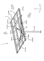
- FIG. 1 is a perspective view showing an overall configuration of a panel support frame 1 according to the present embodiment.
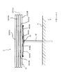
- FIG. 2 is a front view of the panel support base 1 (viewed from direction A in FIG. 1).
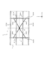
- FIG. 3 is a plan view of the panel support base 1 (viewed from the direction B in FIG. 1).
- FIG. 4 is a side view of the panel support base 1 (viewed from the direction C in FIG. 1).
- the panel support base 1 is a base that is installed on the ground G (installation surface) while supporting, for example, a photovoltaic power generation panel P as a panel.
- a direction orthogonal to the ground G is defined as a Z-axis direction
- two directions orthogonal to the Z-axis and orthogonal to each other in the same plane are defined as an X-axis direction and a Y-axis direction.
- the A direction is parallel to the Y axis direction
- the B direction is parallel to the Z axis direction
- the C direction is parallel to the X axis direction.
- the panel support frame 1 is composed of a plurality of beam members (first support beam 11 and second support beam 12 described later) joined in a lattice shape, and a panel mounting grid 10 to which a photovoltaic power generation panel P is attached, One support column 20 erected on G, a pedestal 30 provided at the upper end of the support column 20, and a plurality (in this embodiment) that extend radially from the pedestal 30 and support the panel mounting grid 10 from below. 4) arm members 40.
- first support beams 11 (11a, 11b) directly supported by the arm members 40 so that the beam members constituting the panel mounting grid 10 are parallel to each other at regular intervals.
- a plurality of (four in this embodiment) second support beams that are installed between adjacent first support beams 11 so as to be orthogonal to each of the first support beams 11 and parallel to each other at a constant interval. 12 (12a, 12b, 12c, 12d).
- the photovoltaic power generation panel P is attached to the panel attachment grid 10 so that the lower surface thereof is supported by the second support beam 12.
- the number, size, material, and the like of the first support beam 11 and the second support beam 12 may be appropriately determined according to the size, the number, etc., of the photovoltaic power generation panels P attached to the panel mounting grid 10.
- the first support beam 11 and the second support beam 12 are a steel material having a shape that can be joined in a state of surface contact with each other.
- the rigidity of the panel mounting grid 10 can be increased.
- a steel material having a rectangular cross section perpendicular to its length direction square steel material
- a cross section shape perpendicular to its length direction is trapezoidal
- Use of a hexagonal or rectangular steel material is preferable in terms of increasing the rigidity of the panel mounting grid 10, simplifying the assembly work, and shortening the construction period.
- the 1st support beam 11 and the 2nd support beam 12 are not limited to said steel material.
- first support beam 11 and the second support beam 12 are joined to each other by bolting using a connection fitting such as an L-shaped fitting (the connection fitting is not always necessary).
- connection fitting such as an L-shaped fitting
- the rigidity of the panel mounting grid 10 can be increased, and at the same time, the assembly workability can be improved.
- the first support beams 11 are arranged at positions symmetrical to each other (that is, a line symmetrical position) across the first center line L1 of the panel mounting grid 10. It is preferable (refer FIG. 3). That is, it is preferable that the first support beams 11a and 11b are arranged at equidistant positions from the first center line L1.
- the first center line L1 is a straight line orthogonal to the second support beam 12 at the center position in the length direction of the second support beam 12 when the panel mounting grid 10 is viewed in plan.
- the second support beams 12 are arranged at symmetrical positions with respect to the second center line L2 of the panel mounting grid 10 when the panel mounting grid 10 is viewed in plan (FIG. 3). reference). That is, the second support beams 12a and 12d are arranged at the same distance from the second center line L2, and the second support beams 12b and 12c are arranged at the same distance from the second center line L2. Preferably it is.
- the second center line L2 is a straight line orthogonal to the first support beam 11 at the center position in the length direction of the first support beam 11 when the panel mounting grid 10 is viewed in plan.
- the panel mounting grid 10 having such a line-symmetric structure is excellent in the weight balance of the front, rear, left and right around the intersection of the first center line L1 and the second center line L2. Accordingly, the panel mounting grid 10 (that is, the photovoltaic power generation panel P) is continuously supported stably with the minimum number of components, that is, one column 20 described later and four arm members 40 extending from the column 20. Becomes easy.
- the panel mounting grid 10 configured as described above is supported from below by an arm member 40 described later so that the photovoltaic power generation panel P is inclined with respect to the ground G (see FIG. 4).
- the inclination angle of the photovoltaic power generation panel P with respect to the ground G may be set to an angle (for example, 0 to 30 °) at which sunlight can be efficiently received according to the area where the panel support frame 1 is installed.
- the column 20 is, for example, a steel pipe pile having a circular cross section perpendicular to the length direction thereof, and is erected on the ground G directly below the panel mounting grid 10.
- the center point of the panel mounting grid 10 (intersection of the first center line L1 and the second center line L2) exists on the extended line of the center axis of the column 20 (see FIG. 3).
- the installation surface of the panel support base 1 is the ground G as in this embodiment, it is preferable that the lower portion of the support column 20 is directly embedded in the ground (see FIGS. 2 and 4). Thereby, it is not necessary to provide a concrete foundation for fixing the support column 20 on the ground surface or in the ground. Of course, it is not always necessary to embed the support column 20 directly in the ground, and a concrete foundation for fixing the support column 20 may be provided depending on the situation.
- the support 20 is not limited to the circular steel pipe pile as described above, and a steel pipe pile having a polygonal cross section, an H-shaped steel pile, a steel sheet pile, or the like may be used.
- the procurement cost of a member can be reduced by using the steel material generally embedded in the ground as the support 20.
- the column 20 is not limited to the above steel material.
- a cradle 30 is provided with a collective fixing member 31 (details will be described later with reference to FIGS. 5 to 8) for fixing the end portions of the four arm members 40 in one place. Is provided.
- the four arm members 40 (41, 42, 43, 44) are arranged so as to extend radially from the collective fixing member 31 of the cradle 30 in plan view, and support the panel mounting grid 10 from below. Yes.
- two arm members 41 and 42 are connected to the first beam member 11a using a joining method such as welding or bolting, and the remaining two members
- the arm members 43 and 44 are connected to the first beam member 11b by using a joining method such as welding or bolting. That is, the first beam member 11a is supported in an inclined state by the arm members 41 and 42, and the first beam member 11b is supported in an inclined state by the arm members 43 and 44.
- the photovoltaic panel P) is supported in an inclined state (see FIG. 4).
- Each arm member 40 is a steel material having a closed cross section (for example, a polygonal cross section such as a square cross section) or an open cross section (a groove cross section, a C cross section, a hat cross section, etc.) as a cross section orthogonal to the length direction. It is preferable.
- the hat-shaped cross section is a cross section having a pair of side wall portions facing each other, a connecting wall portion that connects one end of these side wall portions, and a flange portion that extends in a direction away from the other end of each side wall portion. Point to.
- each arm member 40 is not limited to the steel material described above.
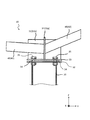
- FIG. 5 is a perspective view showing the overall configuration of the cradle 30.
- FIG. 6 is a front view of the cradle 30 (viewed from the direction A in FIG. 5).
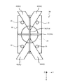
- FIG. 7 is a plan view of the cradle 30 (viewed from the direction B in FIG. 5).
- FIG. 8 is a side view of the cradle 30 (viewed from the direction C in FIG. 5).
- the cradle 30 has a first plate member 32 joined to the upper end of the support column 20 in a state where the upper surface thereof is orthogonal to the length direction (Z-axis direction) of the support column 20, and the upper surface thereof.
- a second plate member 33 bolted with a spacer 34 sandwiched between the first plate member 32 in a state orthogonal to the length direction of the support column 20 is provided.
- the first plate member 32 is preferably joined to the upper end of the support column 20 by a strong joining method such as welding, but may be joined by other joining methods. Further, the second plate member 33 is bolted to the first plate member 32 by four bolts 35, but the spacer 34 may be removed when the height adjustment is not necessary. For the reasons described later, the first plate member 32 and the second plate member 33 are preferably rectangular plate members having the same dimensions. Of course, the shape and dimension of the 1st board
- the assembly fixing member 31 is provided on the upper surface of the second plate member 33.
- the assembly fixing member 31 includes a plurality of (two in the present embodiment) third plate members 31 a and 31 b that are erected so as to intersect with each other at one place on the upper surface of the second plate member 33.
- Each end of each arm member 40 (the end opposite to the end connected to the first support beam 11) is joined to both surfaces of the third plate 31a by a strong joining method such as welding. .
- the arm members 41 and 43 are joined to both sides of the third plate 31a on both sides of the third plate 31b, and the third plate 31b is sandwiched on the other side of the third plate 31a.
- Arm members 42 and 44 are joined to both sides.
- the joining location of the arm member 40 is not limited thereto, and the arm member 40 may be joined to the third plate material 31b, or may be divided into both the third plate material 31a and the third plate material 31b. good.
- the panel support frame 1 of the present embodiment as described above, a configuration in which the panel mounting grid 10 to which the photovoltaic power generation panel P is mounted is supported by the four arm members 40 extending radially from the single column 20 is adopted. Therefore, the number of parts can be reduced and the assembly work can be simplified. As a result, the cost and the construction period can be shortened. Further, when such an arm member 40 is directly joined to the support column 20, a large load is locally applied from the arm member 40 to the support column 20, and each arm member joint portion of the support column 20 is partially deformed. However, in the panel support frame 1 of this embodiment, the end portions of the arm members 40 are gathered at one place in the cradle 30 provided at the upper end of the column 20. By fixing it, the aggregated load can be uniformly distributed and loaded on the entire cross section of the support column 20, so that the rigidity of the entire gantry can be efficiently ensured.
- the panel mounting grid 10, the arm member 40, the collective fixing member 31, and the second plate member 33 can be integrally assembled in advance as a panel mounting unit at a factory or the like.
- the column 20 is set up on the installation surface (ground G) in the field work, and the first plate member 32 is joined to the upper end of the column 20, and then the second plate member 33 of the panel mounting unit is bolted to the first plate member 32. Since the construction method of fastening and completing the gantry can be adopted, the construction efficiency can be improved (that is, the construction period can be shortened).
- the height position of the panel mounting grid 10 (that is, the height position of the photovoltaic power generation panel P) is adjusted locally by bolting the first plate member 32 and the second plate member 33 with the spacer 34 interposed therebetween. Can do.
- the panel support stand 1 of this embodiment since the 1st board
- the second plate member 33 of the panel mounting unit is bolted to the plate member 32, the correct mounting direction of the panel mounting unit can be easily recognized. Thereby, the construction efficiency of the panel support stand 1 can be improved more. In other words, it is possible to prevent the photovoltaic power generation panel P from being fixed in a wrong direction.
- each end of the arm member 40 can be easily fixed in a state where the arm members 40 are gathered in one place with a simple configuration. The number of parts and the construction period can be reduced.
- the panel support stand 1 of this embodiment since the support
- the panel support stand 1 which supports the photovoltaic power generation panel P as a panel was demonstrated, this invention is not restricted to this, The panel and antenna for weather observation, a commercial signboard, etc. It can apply to the panel support stand which supports the panel used for various uses.
- the height position (position of a Z-axis direction) of the photovoltaic power generation panel P is pinched
- a cradle 50 that can adjust the position of the solar power generation panel P in the XYZ triaxial directions may be provided.
- the cradle 50 includes a position adjustment mechanism 51 provided at the upper end of the column 20, and the position adjustment mechanism 51 with the upper surface orthogonal to the length direction of the column 20.
- a fourth plate member 52 joined to the upper portion and a collective fixing member 53 provided on the upper surface of the fourth plate member 52 are provided.
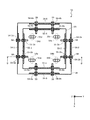
- FIG. 10 is a plan view of the position adjustment mechanism 51.
- 11 is a cross-sectional view of the position adjustment mechanism 51 shown in FIG.
- the position adjustment mechanism 51 includes a square first adjustment plate member 54, a second adjustment plate member 55 that is smaller than the first adjustment plate member 54 and also has a square shape, and four Z-direction adjustment washers. 56, four Z-direction adjusting bolts 57, four Y-direction adjusting bolts 58, and four X-direction adjusting bolts 59.
- the first adjustment plate member 54 is joined to the upper end of the support column 20 with its upper surface orthogonal to the length direction (Z-axis direction) of the support column 20.
- the first adjusting plate member 54 is preferably joined to the upper end of the support column 20 by a strong joining method such as welding, but other joining methods may be used.
- a pair of opposing sides is parallel to the X-axis direction, and the remaining pair of opposing sides is parallel to the Y-axis direction.
- Bolt holes 54a, 54b, 54c, and 54d that are long in the X-axis direction are provided in portions near the four corners of the first adjustment plate member 54, respectively.
- Bolt holes 54-1a and 54-1b that are long in the X-axis direction are provided at two locations on the first side plate 54-1.
- Bolt holes 54-2a and 54-2b that are long in the X-axis direction are provided at two locations on the first side plate 54-2.
- bolt holes 54-3a and 54-3b that are long in the Y-axis direction are provided at two locations on the first side plate 54-3, respectively.
- bolt holes 54-4a and 54-4b that are long in the Y-axis direction are provided at two locations on the first side plate 54-4.
- the second adjustment plate member 55 is bolted to the first adjustment plate member 54 with four Z-direction adjust washers 56 in a state where the upper surface thereof is orthogonal to the length direction of the support column 20.
- the pair of opposing sides is parallel to the X-axis direction, and the remaining pair of opposing sides is parallel to the Y-axis direction.
- the four sides of the second adjustment plate member 55 are second side plates 55 that are shorter than one side of the second adjustment plate member 55 and have the same length as the side plates 54-1 to 54-4 of the first adjustment plate member 54. -1, 55-2, 55-3 and 55-4 are erected.
- the bolt adjustment holes 55a, 55b, 55c, and 55d that are long in the Y-axis direction are provided in portions near the four corners of the second adjustment plate member 55, respectively.
- this state is referred to as a reference position state
- the bolt holes 55a, 55b, 55c, 55d of the second adjustment plate member 55 cross each other (see FIG. 10).
- the Z-direction adjusting bolt 57 penetrates from the lower surface of the first adjustment plate member 54 to the upper surface of the second adjustment plate member 55 via the Z-direction adjustment washer 56 at each of the four bolt hole intersections as described above. After that, it is fixed with a nut (see FIG. 11).
- Ordinary circular bolt holes 55-1a and 55-1b are provided at two locations on the second side plate 55-1.
- the center of the bolt hole 54-1a of the first side plate 54-1 and the center of the bolt hole 55-1a of the second side plate 55-1 coincide with each other on the X axis and the Z axis.
- the center of the bolt hole 54-1b of the first side plate 54-1 and the center of the bolt hole 55-1b of the second side plate 55-1 coincide with each other on the X axis and the Z axis.
- the first Y-direction adjusting bolt 58 passes through the bolt hole 54-1a and the bolt hole 55-1a from the first side plate 54-1 side, and is then fixed with a nut.
- the second Y-direction adjusting bolt 58 passes through the bolt hole 54-1b and the bolt hole 55-1b from the first side plate 54-1 side, and is then fixed with a nut.
- Ordinary circular bolt holes 55-2a and 55-2b are provided at two locations on the second side plate 55-2.
- the center of the bolt hole 54-2a of the first side plate 54-2 and the center of the bolt hole 55-2a of the second side plate 55-2 coincide with each other on the X axis and the Z axis.
- the center of the bolt hole 54-2b of the first side plate 54-2 and the center of the bolt hole 55-2b of the second side plate 55-2 coincide with each other on the X axis and the Z axis.
- the third Y-direction adjusting bolt 58 passes through the bolt hole 54-2a and the bolt hole 55-2a from the first side plate 54-2 side, and is then fixed with a nut.
- the fourth Y-direction adjusting bolt 58 passes through the bolt hole 54-2b and the bolt hole 55-2b from the first side plate 54-2 side, and is then fixed with a nut.
- Ordinary circular bolt holes 55-3a and 55-3b are provided at two locations on the second side plate 55-3, respectively.
- the center of the bolt hole 54-3a of the first side plate 54-3 and the center of the bolt hole 55-3a of the second side plate 55-3 coincide with each other on the Y axis and the Z axis.
- the center of the bolt hole 54-3b of the first side plate 54-3 and the center of the bolt hole 55-3b of the second side plate 55-3 coincide with each other on the Y axis and the Z axis.
- the first X-direction adjusting bolt 59 passes through the bolt hole 54-3a and the bolt hole 55-3a from the first side plate 54-3 side, and is then fixed with a nut.
- the second X-direction adjusting bolt 59 passes through the bolt hole 54-3b and the bolt hole 55-3b from the first side plate 54-3 side, and is then fixed with a nut.
- Ordinary circular bolt holes 55-4a and 55-4b are provided at two locations on the second side plate 55-4, respectively.
- the center of the bolt hole 54-4a of the first side plate 54-4 and the center of the bolt hole 55-4a of the second side plate 55-4 coincide with each other on the Y axis and the Z axis.
- the center of the bolt hole 54-4b of the first side plate 54-4 and the center of the bolt hole 55-4b of the second side plate 55-4 coincide with each other on the Y axis and the Z axis.
- the third X-direction adjusting bolt 59 passes through the bolt hole 54-4a and the bolt hole 55-4a from the first side plate 54-4 side, and is then fixed with a nut.
- the fourth X-direction adjusting bolt 59 passes through the bolt hole 54-4b and the bolt hole 55-4b from the first side plate 54-4 side, and is then fixed with a nut.
- the fourth plate 52 has second side plates 55-1 to 55-1 erected on the second adjustment plate 55 with the upper surface thereof orthogonal to the length direction (Z-axis direction) of the support column 20. It is joined to the upper part of 55-4 by welding or the like.
- the collective fixing member 53 is provided on the upper surface of the fourth plate member 52.
- the assembly fixing member 53 includes two fifth plate members 53 a and 53 b that are erected on the upper surface of the fourth plate member 52 so as to cross each other at a single point.
- Each end of each arm member 40 is joined to both surfaces of the fifth plate member 53a by a strong joining method such as welding. Since the joint location of the arm member 40 in the fifth plate member 53a is the same as that in the above embodiment, the detailed description is omitted.
- the position of the fourth plate member 52 on the X-axis can be adjusted by rotating the X-direction adjusting bolt 59, and the fourth direction by rotating the Y-direction adjusting bolt 58.
- the position of the plate 52 on the Y axis can be adjusted.
- the position of the fourth plate member 52 on the Z-axis can be adjusted by the presence or absence of the Z-direction adjusting washer 56.
- the three-dimensional position of the photovoltaic power generation panel P can be adjusted at the time of mounting the base on the site.
- Such a position adjustment function is particularly effective when it is necessary to arrange the plurality of panel support bases 1 so as to be adjacent to each other.
- the structure of the position adjusting mechanism 51 is not limited to the structure described in the above modification.
- the conditions in the examples are one example of conditions used for confirming the feasibility and effects of the present invention, and the present invention is based on this one example of conditions. It is not limited.
- the present invention can adopt various conditions as long as the object of the present invention is achieved without departing from the gist of the present invention.
- a panel having a vertical dimension of 990 mm and a horizontal dimension of 1650 mm was used, and 12 panels per module (horizontal 3 stages ⁇ 4 rows) were attached to the panel mounting grid.
- the speed pressure for wind load design was set to 2400 N / mm 2 .
- the second support beam has a hexagonal steel pipe (upper side: 100 mm, lower side: 40 mm, height: 75 mm, hypotenuse) as shown in FIG. (Height: 45 mm, plate thickness: 1.6 mm).
- a steel pipe cross-sectional dimension: 125 mm ⁇ 75 mm, plate thickness: 1.6 mm
- a panel mounting grid having a vertical dimension of 3100 mm and a horizontal dimension of 3100 mm when viewed in plan was produced.
- the steel pipe pile (diameter: 114.3 mm, plate
- a steel pipe having a square cross section perpendicular to the length direction (cross-sectional dimension: 50 mm ⁇ 50 mm, plate thickness: 2.3 mm) was used as the arm member.
- a panel support frame for supporting the photovoltaic power generation panel was assembled using the above-mentioned members so that the inclination angle with respect to the ground was 10 °. It took 0.5 days per module from the start of assembly to the completion of construction. Since the normal construction period (for example, in the case of Patent Document 1) is 10 days, it was confirmed that the construction period can be greatly shortened by the present invention.
- the present invention it is possible to provide a panel support frame having a simple structure, simple assembly work, low cost, a short construction period, and excellent panel support strength. Therefore, a large industrial effect can be expected by implementing the present invention.
Landscapes
- Engineering & Computer Science (AREA)
- Chemical & Material Sciences (AREA)
- Life Sciences & Earth Sciences (AREA)
- Sustainable Development (AREA)
- Sustainable Energy (AREA)
- Thermal Sciences (AREA)
- Physics & Mathematics (AREA)
- Combustion & Propulsion (AREA)
- Mechanical Engineering (AREA)
- General Engineering & Computer Science (AREA)
- Photovoltaic Devices (AREA)
- Rod-Shaped Construction Members (AREA)
- Fencing (AREA)
Abstract
Description
本願は、2012年01月06日に、日本に出願された特願2012-001482号に基づき優先権を主張し、その内容をここに援用する。
この架台において、太陽電池パネルは、取付フレームと取付ビームとで形成される取付スペースに取付けられる。支柱の高さが前後で異なっているため、太陽電池パネルを太陽に向けて傾斜させた状態で支持できる。
すなわち、
(1)本発明の一態様に係るパネル支持架台は、パネルを支持した状態で据付面に設置されるパネル支持架台であって、格子状に接合された複数の梁部材で構成され、前記パネルが取付けられるパネル取付格子と;前記据付面に立設された一本の支柱と;前記支柱の上端に設けられた受台と;平面視した場合に、前記受台から放射状に延びるように配置され、前記パネル取付格子を下方から支持する複数の腕部材と;を備え、前記受台が、前記複数の腕部材のそれぞれの端部を一箇所に集合させて固定する集合固定部材を備える。
また、このような腕部材を直接支柱に接合すると、腕部材から支柱に局所的に大きな荷重が加わって、支柱の各腕部材接合部が部分的に変形したり、その結果として支柱が折れ曲がったりする可能性があるが、上記(1)に記載のパネル支持架台では、支柱の上端に設けられた受台において、複数の腕部材のそれぞれの端部を一箇所に集合させて固定することにより、支柱の断面全体に、集約した荷重を均一に分散し負担させることができるので、架台全体としての剛性を効率的に高めることができる。
また、第1板材と第2板材とをスペーサーを挟んでボルト締めすれば、パネル取付格子の高さ位置(つまりパネルの高さ位置)を現地で調整することができる。
この場合、例えば、第1板材と第2板材とが完全に重なった状態でボルト締めした時に、パネル取付ユニット(つまりパネル)が正しい方向を向くようにボルト穴を形成しておけば良い。
図1は、本実施形態に係るパネル支持架台1の全体構成を示す斜視図である。図2は、パネル支持架台1の正面図(図1中のA方向から視た図)である。図3は、パネル支持架台1の平面図(図1中のB方向から視た図)である。図4は、パネル支持架台1の側面図(図1中のC方向から視た図)である。
図5は、受台30の全体構成を示す斜視図である。図6は、受台30の正面図(図5のA方向から視た図)である。図7は、受台30の平面図(図5のB方向から視た図)である。図8は、受台30の側面図(図5のC方向から視た図)である。
また、このような腕部材40を直接支柱20に接合すると、腕部材40から支柱20に局所的に大きな荷重が加わって、支柱20の各腕部材接合部が部分的に変形したり、その結果として支柱20が折れ曲がったりする可能性があるが、本実施形態のパネル支持架台1では、支柱20の上端に設けられた受台30において、各腕部材40のそれぞれの端部を一箇所に集合させて固定することにより、支柱20の断面全体に、集約した荷重を均一に分散し負担させることができるので、架台全体としての剛性を効率的に確保できる。
また、第1板材32と第2板材33とをスペーサー34を挟んでボルト締めすることにより、パネル取付格子10の高さ位置(つまり太陽光発電パネルPの高さ位置)を現地で調整することができる。
この場合、例えば、第1板材32と第2板材33とが完全に重なった状態でボルト締めした時に、パネル取付ユニット(つまり太陽光発電パネルP)が正しい方向を向くようにボルト穴を形成しておけば良い。
(1)例えば、上記実施形態では、第1支持梁11が腕部材40によって支持される構成を例示したが、第2支持梁12が腕部材40によって支持されても良いし、或いは、第1支持梁11及び第2支持梁12の両方が腕部材40によって支持されても良い。
一方、第1側板54-3の2箇所には、それぞれ、Y軸方向に長いボルト穴54-3a及び54-3bが設けられている。同様に、第1側板54-4の2箇所には、Y軸方向に長いボルト穴54-4a及び54-4bが設けられている。
第2調整板材55の4辺のうち、対向する一対の辺はX軸方向と平行であり、残りの対向する一対の辺はY軸方向と平行である。また、第2調整板材55の4辺には、第2調整板材55の一辺の長さより短く、且つ第1調整板材54の各側板54-1~54-4と長さの等しい第2側板55-1、55-2、55-3、55-4が立設されている。
また、本実施例では、第1支持梁として、その長さ方向に直交する断面の形状が角形(矩形)の鋼管(断面寸法:125mm×75mm、板厚:1.6mm)を用いた。
これらの第1支持梁及び第2支持梁を用いて、平面視した場合の縦寸法が3100mm、横寸法が3100mmのパネル取付格子を作製した。
また、本実施例では、支柱として、その長さ方向に直交する断面の形状が円形の鋼管杭(直径:114.3mm、板厚:2.8mm)を用いた。
また、本実施例では、腕部材として、その長さ方向に直交する断面の形状が角形の鋼管(断面寸法:50mm×50mm、板厚:2.3mm)を用いた。
10 パネル取付格子
11(11a、11b) 第1支持梁
12(11a、11b、11c、11d) 第2支持梁
20 支柱
30 受台
31 集合固定部材
31a、31b 第3板材
32 第1板材
33 第2板材
34 スペーサー
35 ボルト
40(41、42、43、44) 腕部材
50 受台
51 位置調整機構
52 第4板材
53 集合固定部材
53a、53b 第5板材
54 第1調整板材
55 第2調整板材
56 Z方向アジャストワッシャ
57 Z方向アジャストボルト
58 Y方向アジャストボルト
59 X方向アジャストボルト
P 太陽光発電パネル
Claims (13)
- パネルを支持した状態で据付面に設置されるパネル支持架台であって、
格子状に接合された複数の梁部材で構成され、前記パネルが取付けられるパネル取付格子と;
前記据付面に立設された一本の支柱と;
前記支柱の上端に設けられた受台と;
平面視した場合に、前記受台から放射状に延びるように配置され、前記パネル取付格子を下方から支持する複数の腕部材と;
を備え、
前記受台は、前記複数の腕部材のそれぞれの端部を一箇所に集合させて固定する集合固定部材を備える
ことを特徴とするパネル支持架台。 - 前記受台は、
その上面が前記支柱の長さ方向に直交した状態で、前記支柱の上端に接合された第1板材と;
その上面が前記支柱の長さ方向に直交した状態で、前記第1板材に、直接、或いはスペーサーを挟んでボルト締めされた第2板材と;
をさらに備え、
前記集合固定部材は、前記第2板材の上面に設けられている
ことを特徴とする請求項1に記載のパネル支持架台。 - 前記第1板材及び前記第2板材は、同一寸法の長方形状の板材であることを特徴とする請求項2に記載のパネル支持架台。
- 前記集合固定部材は、前記第2板材の上面において、互いに一箇所で交差するように立設された複数の第3板材を含み;
平面視した場合に、前記複数の第3板材の交差部が、前記支柱の中心軸線の延長線上に存在し;
前記複数の腕部材のそれぞれの端部が、前記複数の第3板材の少なくとも一つに接合されている;
ことを特徴とする請求項2に記載のパネル支持架台。 - 前記受台は、
前記支柱の上端に設けられた位置調整機構と;
その上面が前記支柱の長さ方向に直交した状態で、前記位置調整機構の上部に接合された第4板材と;
をさらに備え、
前記集合固定部材は、前記第4板材の上面に設けられており;
前記位置調整機構は、前記第4板材の、前記支柱の長さ方向の位置調整、及び前記支柱の長さ方向に直交する方向の位置調整を自在とする構造を有する;
ことを特徴とする請求項1に記載のパネル支持架台。 - 前記集合固定部材は、前記第4板材の上面において、互いに一箇所で交差するように立設された複数の第5板材を含み;
平面視した場合に、前記複数の第5板材の交差部が、前記支柱の中心軸線の延長線上に存在し;
前記複数の腕部材のそれぞれの端部が、前記複数の第5板材の少なくとも一つに接合されている;
ことを特徴とする請求項5に記載のパネル支持架台。 - 前記パネル取付格子は、前記パネルが前記据付面に対して傾斜するように前記腕部材によって下方から支持されていることを特徴とする請求項1~6のいずれか一項に記載のパネル支持架台。
- 前記据付面が地面であり、
前記支柱の下部が、地中に直接埋め込まれていることを特徴とする請求項1~6のいずれか一項に記載のパネル支持架台。 - 前記支柱は、その長さ方向に直交する断面の形状が円形或いは多角形の鋼管杭、H形鋼杭、または鋼矢板であることを特徴とする請求項8に記載のパネル支持架台。
- 前記梁部材は、
一定間隔で互いに平行となるように、前記複数の腕部材によって直接支持された複数の第1支持梁と;
前記第1支持梁のそれぞれと直交し、且つ一定間隔で互いに平行となるように、隣り合う前記第1支持梁の間に架設された複数の第2支持梁と;
を含み、
前記パネルは、その下面が前記第2支持梁で支持されている;
ことを特徴とする請求項1~6のいずれか一項に記載のパネル支持架台。 - 前記第1支持梁及び前記第2支持梁は、互いに面接触した状態で接合可能な形状を有する鋼材であることを特徴とする請求項10に記載のパネル支持架台。
- 前記第1支持梁及び前記第2支持梁は、ボルト締めによって互いに接合されていることを特徴とする請求項10に記載のパネル支持架台。
- 前記各腕部材は、それぞれ、その長さ方向に直交する断面として閉鎖断面或いは開放断面を有する鋼材であることを特徴とする請求項1~6のいずれか一項に記載のパネル支持架台。
Priority Applications (3)
| Application Number | Priority Date | Filing Date | Title |
|---|---|---|---|
| KR1020147017785A KR101465945B1 (ko) | 2012-01-06 | 2012-12-27 | 패널 지지 가대 |
| JP2013518881A JP5472535B2 (ja) | 2012-01-06 | 2012-12-27 | パネル支持架台 |
| PH12014501515A PH12014501515A1 (en) | 2012-01-06 | 2014-06-30 | Panel supporting mount |
Applications Claiming Priority (2)
| Application Number | Priority Date | Filing Date | Title |
|---|---|---|---|
| JP2012-001482 | 2012-01-06 | ||
| JP2012001482 | 2012-01-06 |
Publications (1)
| Publication Number | Publication Date |
|---|---|
| WO2013103131A1 true WO2013103131A1 (ja) | 2013-07-11 |
Family
ID=48745191
Family Applications (1)
| Application Number | Title | Priority Date | Filing Date |
|---|---|---|---|
| PCT/JP2012/083987 Ceased WO2013103131A1 (ja) | 2012-01-06 | 2012-12-27 | パネル支持架台 |
Country Status (5)
| Country | Link |
|---|---|
| JP (1) | JP5472535B2 (ja) |
| KR (1) | KR101465945B1 (ja) |
| MY (1) | MY173894A (ja) |
| PH (1) | PH12014501515A1 (ja) |
| WO (1) | WO2013103131A1 (ja) |
Cited By (4)
| Publication number | Priority date | Publication date | Assignee | Title |
|---|---|---|---|---|
| JP2015055111A (ja) * | 2013-09-12 | 2015-03-23 | 株式会社藤原設備 | 太陽電池パネル架台用支持体 |
| JP2015055110A (ja) * | 2013-09-12 | 2015-03-23 | 株式会社藤原設備 | 太陽電池パネル架台用支持体 |
| JP2015183363A (ja) * | 2014-03-20 | 2015-10-22 | 公益財団法人鉄道総合技術研究所 | 小口径角型棒状補強体による土構造物の耐震・耐降雨対策斜面安定化工法 |
| KR20220060427A (ko) * | 2020-11-04 | 2022-05-11 | 단국대학교 천안캠퍼스 산학협력단 | 암거형 생태통로용 관 및 이를 이용한 양서류를 위한 생태통로 조립체 |
Citations (2)
| Publication number | Priority date | Publication date | Assignee | Title |
|---|---|---|---|---|
| JPH068990U (ja) * | 1991-01-23 | 1994-02-04 | 株式会社ディー・エヌ・エー | 電飾広告装置 |
| JP2011220096A (ja) * | 2010-03-25 | 2011-11-04 | Sharp Corp | 構造物用架台、その架台の施工方法、及びその架台を用いた太陽光発電システム |
Family Cites Families (2)
| Publication number | Priority date | Publication date | Assignee | Title |
|---|---|---|---|---|
| JPH036588A (ja) * | 1989-06-05 | 1991-01-14 | Japan Radio Co Ltd | Cai装置 |
| JP2006351665A (ja) * | 2005-06-14 | 2006-12-28 | Matsushita Electric Ind Co Ltd | 太陽光発電装置 |
-
2012
- 2012-12-27 KR KR1020147017785A patent/KR101465945B1/ko active Active
- 2012-12-27 MY MYPI2014701799A patent/MY173894A/en unknown
- 2012-12-27 JP JP2013518881A patent/JP5472535B2/ja not_active Expired - Fee Related
- 2012-12-27 WO PCT/JP2012/083987 patent/WO2013103131A1/ja not_active Ceased
-
2014
- 2014-06-30 PH PH12014501515A patent/PH12014501515A1/en unknown
Patent Citations (2)
| Publication number | Priority date | Publication date | Assignee | Title |
|---|---|---|---|---|
| JPH068990U (ja) * | 1991-01-23 | 1994-02-04 | 株式会社ディー・エヌ・エー | 電飾広告装置 |
| JP2011220096A (ja) * | 2010-03-25 | 2011-11-04 | Sharp Corp | 構造物用架台、その架台の施工方法、及びその架台を用いた太陽光発電システム |
Cited By (5)
| Publication number | Priority date | Publication date | Assignee | Title |
|---|---|---|---|---|
| JP2015055111A (ja) * | 2013-09-12 | 2015-03-23 | 株式会社藤原設備 | 太陽電池パネル架台用支持体 |
| JP2015055110A (ja) * | 2013-09-12 | 2015-03-23 | 株式会社藤原設備 | 太陽電池パネル架台用支持体 |
| JP2015183363A (ja) * | 2014-03-20 | 2015-10-22 | 公益財団法人鉄道総合技術研究所 | 小口径角型棒状補強体による土構造物の耐震・耐降雨対策斜面安定化工法 |
| KR20220060427A (ko) * | 2020-11-04 | 2022-05-11 | 단국대학교 천안캠퍼스 산학협력단 | 암거형 생태통로용 관 및 이를 이용한 양서류를 위한 생태통로 조립체 |
| KR102455207B1 (ko) * | 2020-11-04 | 2022-10-14 | 단국대학교 천안캠퍼스 산학협력단 | 암거형 생태통로용 관 및 이를 이용한 양서류를 위한 생태통로 조립체 |
Also Published As
| Publication number | Publication date |
|---|---|
| PH12014501515B1 (en) | 2014-10-08 |
| JPWO2013103131A1 (ja) | 2015-05-11 |
| PH12014501515A1 (en) | 2014-10-08 |
| MY173894A (en) | 2020-02-26 |
| KR101465945B1 (ko) | 2014-11-27 |
| JP5472535B2 (ja) | 2014-04-16 |
| KR20140094029A (ko) | 2014-07-29 |
Similar Documents
| Publication | Publication Date | Title |
|---|---|---|
| JP2014034830A (ja) | 太陽電池パネルの設置架台、及び、太陽電池パネルの設置方法 | |
| JP6026131B2 (ja) | 機能パネル支持架台 | |
| JP5472535B2 (ja) | パネル支持架台 | |
| JP2017040068A (ja) | 建築構造、建築物及び建築物の工法 | |
| JP2012215067A (ja) | 太陽光パネル架台 | |
| JP2015104245A (ja) | 太陽光発電パネル架台 | |
| JP2014148822A (ja) | 折板屋根に対する太陽電池アレイの据付装置 | |
| JP2014088708A (ja) | 太陽電池モジュール用の載置架台及び太陽光発電装置 | |
| CN118581974B (zh) | 一种装配式预应力bipv空间网格结构体系 | |
| JP3181778U (ja) | 太陽光発電パネル支持架台 | |
| JP2015195701A (ja) | 太陽電池パネル架台 | |
| JP2014148820A (ja) | 太陽電池アレイの据付装置 | |
| JP2014212177A (ja) | 太陽電池アレイの据付装置 | |
| JP2013119727A (ja) | 太陽光モジュール取付架台用ユニット | |
| JP5403189B1 (ja) | パネル支持架台 | |
| JP2014148821A (ja) | 太陽電池アレイ据付装置 | |
| JP6021588B2 (ja) | 架台 | |
| JP2014212176A (ja) | 太陽電池アレイの据付装置 | |
| JP5442665B2 (ja) | 太陽電池モジュールの取付架台 | |
| JP6017261B2 (ja) | 架台 | |
| JP6739856B2 (ja) | 太陽光発電パネル設置用架台、太陽電池アレイ及び太陽光発電パネル | |
| KR20170111947A (ko) | 태양 전지판 지지 장치 | |
| JP3185699U (ja) | 太陽電池パネル用架台 | |
| JP6332589B2 (ja) | ソーラーパネルユニット | |
| JP2013204281A (ja) | 付属ユニット及びユニット建物 |
Legal Events
| Date | Code | Title | Description |
|---|---|---|---|
| ENP | Entry into the national phase |
Ref document number: 2013518881 Country of ref document: JP Kind code of ref document: A |
|
| 121 | Ep: the epo has been informed by wipo that ep was designated in this application |
Ref document number: 12864562 Country of ref document: EP Kind code of ref document: A1 |
|
| ENP | Entry into the national phase |
Ref document number: 20147017785 Country of ref document: KR Kind code of ref document: A |
|
| NENP | Non-entry into the national phase |
Ref country code: DE |
|
| 122 | Ep: pct application non-entry in european phase |
Ref document number: 12864562 Country of ref document: EP Kind code of ref document: A1 |