WO2013105206A1 - Matériau pour élément électroluminescent organique, et élément comprenant ce matériau - Google Patents
Matériau pour élément électroluminescent organique, et élément comprenant ce matériau Download PDFInfo
- Publication number
- WO2013105206A1 WO2013105206A1 PCT/JP2012/008442 JP2012008442W WO2013105206A1 WO 2013105206 A1 WO2013105206 A1 WO 2013105206A1 JP 2012008442 W JP2012008442 W JP 2012008442W WO 2013105206 A1 WO2013105206 A1 WO 2013105206A1
- Authority
- WO
- WIPO (PCT)
- Prior art keywords
- group
- ring
- substituted
- organic
- unsubstituted
- Prior art date
- Legal status (The legal status is an assumption and is not a legal conclusion. Google has not performed a legal analysis and makes no representation as to the accuracy of the status listed.)
- Ceased
Links
- 0 CC1=C(C=CC=C)C2=CI=CC=C2N1* Chemical compound CC1=C(C=CC=C)C2=CI=CC=C2N1* 0.000 description 1
Images

Classifications
-
- C—CHEMISTRY; METALLURGY
- C07—ORGANIC CHEMISTRY
- C07D—HETEROCYCLIC COMPOUNDS
- C07D491/00—Heterocyclic compounds containing in the condensed ring system both one or more rings having oxygen atoms as the only ring hetero atoms and one or more rings having nitrogen atoms as the only ring hetero atoms, not provided for by groups C07D451/00 - C07D459/00, C07D463/00, C07D477/00 or C07D489/00
- C07D491/02—Heterocyclic compounds containing in the condensed ring system both one or more rings having oxygen atoms as the only ring hetero atoms and one or more rings having nitrogen atoms as the only ring hetero atoms, not provided for by groups C07D451/00 - C07D459/00, C07D463/00, C07D477/00 or C07D489/00 in which the condensed system contains two hetero rings
- C07D491/04—Ortho-condensed systems
- C07D491/044—Ortho-condensed systems with only one oxygen atom as ring hetero atom in the oxygen-containing ring
- C07D491/048—Ortho-condensed systems with only one oxygen atom as ring hetero atom in the oxygen-containing ring the oxygen-containing ring being five-membered
-
- C—CHEMISTRY; METALLURGY
- C07—ORGANIC CHEMISTRY
- C07D—HETEROCYCLIC COMPOUNDS
- C07D209/00—Heterocyclic compounds containing five-membered rings, condensed with other rings, with one nitrogen atom as the only ring hetero atom
- C07D209/56—Ring systems containing three or more rings
- C07D209/80—[b, c]- or [b, d]-condensed
- C07D209/82—Carbazoles; Hydrogenated carbazoles
-
- C—CHEMISTRY; METALLURGY
- C07—ORGANIC CHEMISTRY
- C07D—HETEROCYCLIC COMPOUNDS
- C07D403/00—Heterocyclic compounds containing two or more hetero rings, having nitrogen atoms as the only ring hetero atoms, not provided for by group C07D401/00
- C07D403/14—Heterocyclic compounds containing two or more hetero rings, having nitrogen atoms as the only ring hetero atoms, not provided for by group C07D401/00 containing three or more hetero rings
-
- C—CHEMISTRY; METALLURGY
- C07—ORGANIC CHEMISTRY
- C07D—HETEROCYCLIC COMPOUNDS
- C07D471/00—Heterocyclic compounds containing nitrogen atoms as the only ring hetero atoms in the condensed system, at least one ring being a six-membered ring with one nitrogen atom, not provided for by groups C07D451/00 - C07D463/00
- C07D471/02—Heterocyclic compounds containing nitrogen atoms as the only ring hetero atoms in the condensed system, at least one ring being a six-membered ring with one nitrogen atom, not provided for by groups C07D451/00 - C07D463/00 in which the condensed system contains two hetero rings
- C07D471/04—Ortho-condensed systems
-
- C—CHEMISTRY; METALLURGY
- C07—ORGANIC CHEMISTRY
- C07D—HETEROCYCLIC COMPOUNDS
- C07D495/00—Heterocyclic compounds containing in the condensed system at least one hetero ring having sulfur atoms as the only ring hetero atoms
- C07D495/02—Heterocyclic compounds containing in the condensed system at least one hetero ring having sulfur atoms as the only ring hetero atoms in which the condensed system contains two hetero rings
- C07D495/04—Ortho-condensed systems
-
- C—CHEMISTRY; METALLURGY
- C09—DYES; PAINTS; POLISHES; NATURAL RESINS; ADHESIVES; COMPOSITIONS NOT OTHERWISE PROVIDED FOR; APPLICATIONS OF MATERIALS NOT OTHERWISE PROVIDED FOR
- C09K—MATERIALS FOR MISCELLANEOUS APPLICATIONS, NOT PROVIDED FOR ELSEWHERE
- C09K11/00—Luminescent materials, e.g. electroluminescent or chemiluminescent
- C09K11/06—Luminescent materials, e.g. electroluminescent or chemiluminescent containing organic luminescent materials
-
- H—ELECTRICITY
- H10—SEMICONDUCTOR DEVICES; ELECTRIC SOLID-STATE DEVICES NOT OTHERWISE PROVIDED FOR
- H10K—ORGANIC ELECTRIC SOLID-STATE DEVICES
- H10K50/00—Organic light-emitting devices
-
- H—ELECTRICITY
- H10—SEMICONDUCTOR DEVICES; ELECTRIC SOLID-STATE DEVICES NOT OTHERWISE PROVIDED FOR
- H10K—ORGANIC ELECTRIC SOLID-STATE DEVICES
- H10K50/00—Organic light-emitting devices
- H10K50/10—OLEDs or polymer light-emitting diodes [PLED]
- H10K50/11—OLEDs or polymer light-emitting diodes [PLED] characterised by the electroluminescent [EL] layers
-
- H—ELECTRICITY
- H10—SEMICONDUCTOR DEVICES; ELECTRIC SOLID-STATE DEVICES NOT OTHERWISE PROVIDED FOR
- H10K—ORGANIC ELECTRIC SOLID-STATE DEVICES
- H10K50/00—Organic light-emitting devices
- H10K50/10—OLEDs or polymer light-emitting diodes [PLED]
- H10K50/11—OLEDs or polymer light-emitting diodes [PLED] characterised by the electroluminescent [EL] layers
- H10K50/125—OLEDs or polymer light-emitting diodes [PLED] characterised by the electroluminescent [EL] layers specially adapted for multicolour light emission, e.g. for emitting white light
-
- H—ELECTRICITY
- H10—SEMICONDUCTOR DEVICES; ELECTRIC SOLID-STATE DEVICES NOT OTHERWISE PROVIDED FOR
- H10K—ORGANIC ELECTRIC SOLID-STATE DEVICES
- H10K85/00—Organic materials used in the body or electrodes of devices covered by this subclass
- H10K85/60—Organic compounds having low molecular weight
- H10K85/649—Aromatic compounds comprising a hetero atom
- H10K85/654—Aromatic compounds comprising a hetero atom comprising only nitrogen as heteroatom
-
- H—ELECTRICITY
- H10—SEMICONDUCTOR DEVICES; ELECTRIC SOLID-STATE DEVICES NOT OTHERWISE PROVIDED FOR
- H10K—ORGANIC ELECTRIC SOLID-STATE DEVICES
- H10K85/00—Organic materials used in the body or electrodes of devices covered by this subclass
- H10K85/60—Organic compounds having low molecular weight
- H10K85/649—Aromatic compounds comprising a hetero atom
- H10K85/657—Polycyclic condensed heteroaromatic hydrocarbons
-
- H—ELECTRICITY
- H10—SEMICONDUCTOR DEVICES; ELECTRIC SOLID-STATE DEVICES NOT OTHERWISE PROVIDED FOR
- H10K—ORGANIC ELECTRIC SOLID-STATE DEVICES
- H10K85/00—Organic materials used in the body or electrodes of devices covered by this subclass
- H10K85/60—Organic compounds having low molecular weight
- H10K85/649—Aromatic compounds comprising a hetero atom
- H10K85/657—Polycyclic condensed heteroaromatic hydrocarbons
- H10K85/6572—Polycyclic condensed heteroaromatic hydrocarbons comprising only nitrogen in the heteroaromatic polycondensed ring system, e.g. phenanthroline or carbazole
-
- C—CHEMISTRY; METALLURGY
- C09—DYES; PAINTS; POLISHES; NATURAL RESINS; ADHESIVES; COMPOSITIONS NOT OTHERWISE PROVIDED FOR; APPLICATIONS OF MATERIALS NOT OTHERWISE PROVIDED FOR
- C09K—MATERIALS FOR MISCELLANEOUS APPLICATIONS, NOT PROVIDED FOR ELSEWHERE
- C09K2211/00—Chemical nature of organic luminescent or tenebrescent compounds
- C09K2211/10—Non-macromolecular compounds
- C09K2211/1018—Heterocyclic compounds
- C09K2211/1025—Heterocyclic compounds characterised by ligands
- C09K2211/1029—Heterocyclic compounds characterised by ligands containing one nitrogen atom as the heteroatom
-
- C—CHEMISTRY; METALLURGY
- C09—DYES; PAINTS; POLISHES; NATURAL RESINS; ADHESIVES; COMPOSITIONS NOT OTHERWISE PROVIDED FOR; APPLICATIONS OF MATERIALS NOT OTHERWISE PROVIDED FOR
- C09K—MATERIALS FOR MISCELLANEOUS APPLICATIONS, NOT PROVIDED FOR ELSEWHERE
- C09K2211/00—Chemical nature of organic luminescent or tenebrescent compounds
- C09K2211/10—Non-macromolecular compounds
- C09K2211/1018—Heterocyclic compounds
- C09K2211/1025—Heterocyclic compounds characterised by ligands
- C09K2211/1029—Heterocyclic compounds characterised by ligands containing one nitrogen atom as the heteroatom
- C09K2211/1033—Heterocyclic compounds characterised by ligands containing one nitrogen atom as the heteroatom with oxygen
-
- C—CHEMISTRY; METALLURGY
- C09—DYES; PAINTS; POLISHES; NATURAL RESINS; ADHESIVES; COMPOSITIONS NOT OTHERWISE PROVIDED FOR; APPLICATIONS OF MATERIALS NOT OTHERWISE PROVIDED FOR
- C09K—MATERIALS FOR MISCELLANEOUS APPLICATIONS, NOT PROVIDED FOR ELSEWHERE
- C09K2211/00—Chemical nature of organic luminescent or tenebrescent compounds
- C09K2211/10—Non-macromolecular compounds
- C09K2211/1018—Heterocyclic compounds
- C09K2211/1025—Heterocyclic compounds characterised by ligands
- C09K2211/1044—Heterocyclic compounds characterised by ligands containing two nitrogen atoms as heteroatoms
-
- C—CHEMISTRY; METALLURGY
- C09—DYES; PAINTS; POLISHES; NATURAL RESINS; ADHESIVES; COMPOSITIONS NOT OTHERWISE PROVIDED FOR; APPLICATIONS OF MATERIALS NOT OTHERWISE PROVIDED FOR
- C09K—MATERIALS FOR MISCELLANEOUS APPLICATIONS, NOT PROVIDED FOR ELSEWHERE
- C09K2211/00—Chemical nature of organic luminescent or tenebrescent compounds
- C09K2211/10—Non-macromolecular compounds
- C09K2211/1018—Heterocyclic compounds
- C09K2211/1025—Heterocyclic compounds characterised by ligands
- C09K2211/1074—Heterocyclic compounds characterised by ligands containing more than three nitrogen atoms as heteroatoms
-
- C—CHEMISTRY; METALLURGY
- C09—DYES; PAINTS; POLISHES; NATURAL RESINS; ADHESIVES; COMPOSITIONS NOT OTHERWISE PROVIDED FOR; APPLICATIONS OF MATERIALS NOT OTHERWISE PROVIDED FOR
- C09K—MATERIALS FOR MISCELLANEOUS APPLICATIONS, NOT PROVIDED FOR ELSEWHERE
- C09K2211/00—Chemical nature of organic luminescent or tenebrescent compounds
- C09K2211/18—Metal complexes
- C09K2211/185—Metal complexes of the platinum group, i.e. Os, Ir, Pt, Ru, Rh or Pd
-
- H—ELECTRICITY
- H10—SEMICONDUCTOR DEVICES; ELECTRIC SOLID-STATE DEVICES NOT OTHERWISE PROVIDED FOR
- H10K—ORGANIC ELECTRIC SOLID-STATE DEVICES
- H10K2101/00—Properties of the organic materials covered by group H10K85/00
- H10K2101/10—Triplet emission
-
- H—ELECTRICITY
- H10—SEMICONDUCTOR DEVICES; ELECTRIC SOLID-STATE DEVICES NOT OTHERWISE PROVIDED FOR
- H10K—ORGANIC ELECTRIC SOLID-STATE DEVICES
- H10K50/00—Organic light-emitting devices
- H10K50/10—OLEDs or polymer light-emitting diodes [PLED]
- H10K50/11—OLEDs or polymer light-emitting diodes [PLED] characterised by the electroluminescent [EL] layers
- H10K50/125—OLEDs or polymer light-emitting diodes [PLED] characterised by the electroluminescent [EL] layers specially adapted for multicolour light emission, e.g. for emitting white light
- H10K50/13—OLEDs or polymer light-emitting diodes [PLED] characterised by the electroluminescent [EL] layers specially adapted for multicolour light emission, e.g. for emitting white light comprising stacked EL layers within one EL unit
- H10K50/131—OLEDs or polymer light-emitting diodes [PLED] characterised by the electroluminescent [EL] layers specially adapted for multicolour light emission, e.g. for emitting white light comprising stacked EL layers within one EL unit with spacer layers between the electroluminescent layers
-
- H—ELECTRICITY
- H10—SEMICONDUCTOR DEVICES; ELECTRIC SOLID-STATE DEVICES NOT OTHERWISE PROVIDED FOR
- H10K—ORGANIC ELECTRIC SOLID-STATE DEVICES
- H10K85/00—Organic materials used in the body or electrodes of devices covered by this subclass
- H10K85/30—Coordination compounds
- H10K85/341—Transition metal complexes, e.g. Ru(II)polypyridine complexes
- H10K85/342—Transition metal complexes, e.g. Ru(II)polypyridine complexes comprising iridium
Definitions
- the present invention relates to a novel compound suitable for a material for an organic electroluminescence device and an organic electroluminescence device using the same.
- Organic electroluminescence (EL) elements include a fluorescent type and a phosphorescent type, and an optimum element design has been studied according to each light emission mechanism. With respect to phosphorescent organic EL elements, it is known from their light emission characteristics that high-performance elements cannot be obtained by simple diversion of fluorescent element technology. The reason is generally considered as follows. First, since phosphorescence emission is emission using triplet excitons, the energy gap of the compound used for the light emitting layer must be large. This is because the value of the energy gap (hereinafter also referred to as singlet energy) of a compound usually refers to the triplet energy of the compound (in the present invention, the energy difference between the lowest excited triplet state and the ground state). This is because it is larger than the value of).
- a host material having a triplet energy larger than the triplet energy of the phosphorescent dopant material must first be used for the light emitting layer. I must. Furthermore, it is desirable to provide an electron transport layer and a hole transport layer adjacent to the light emitting layer, and use a compound having a triplet energy higher than that of the phosphorescent dopant material for the electron transport layer and the hole transport layer.
- a compound having a larger energy gap than the compound used for the fluorescent organic EL element is used for the phosphorescent organic EL element. The drive voltage of the entire element increases.
- hydrocarbon compounds having high oxidation resistance and reduction resistance which are useful in fluorescent elements, generally have a small energy gap because of the large spread of ⁇ electron clouds. Therefore, in a phosphorescent organic EL element, it is difficult to select such a hydrocarbon compound, and an organic compound containing a heteroatom such as oxygen or nitrogen is selected. As a result, the phosphorescent organic EL element is There is a problem that the lifetime is shorter than that of a fluorescent organic EL element.
- the exciton relaxation rate of the triplet exciton of the phosphorescent dopant material is much longer than that of the singlet exciton also greatly affects the device performance. That is, since light emitted from singlet excitons has a high relaxation rate that leads to light emission, it is difficult for excitons to diffuse into the peripheral layer of the light emitting layer (for example, a hole transport layer or an electron transport layer). Light emission is expected. On the other hand, light emission from triplet excitons is spin-forbidden and has a slow relaxation rate, so that excitons are likely to diffuse into the peripheral layer, and thermal energy deactivation occurs from other than specific phosphorescent compounds. End up. That is, control of the recombination region of electrons and holes is more important than the fluorescent organic EL element.
- Patent Documents 1 and 2 disclose, as organic EL element materials, 3,3-biscarbazole in which two carbazoles are bonded to each other at the 3-position as a mother skeleton, and the two carbazoles have a heteroaromatic ring. Compounds having substituents attached thereto are disclosed.
- Patent Document 3 discloses a compound in which biscarbazole is used as a mother skeleton, and a nitrogen-containing aromatic ring substituent is bonded to the two carbazoles.
- Patent Document 4 discloses a compound in which biscarbazole is used as a mother skeleton, and the carbazole skeleton is further bonded to the two carbazoles.
- An object of the present invention is to provide a material having a high triplet energy that can be used as a material of an organic EL element that emits phosphorescence.
- a compound represented by the following formula (1) [In Formula (1), L, Q 1 and Q 2 each represent a single bond or a linking group. A represents a substituted or unsubstituted nitrogen-containing heterocyclic group having 5 to 10 ring atoms.
- X 1 to X 8 each represent a carbon atom bonded to Q 2 , CH or N. However, at least one of X 1 to X 8 is N.
- Y represents a nitrogen atom, or NR 5 that binds O, S, the Q 2.
- R 1 to R 5 are each a substituted or unsubstituted aryl group having 6 to 18 ring carbon atoms, a substituted or unsubstituted heteroaryl group having 5 to 18 ring atoms, a substituted or unsubstituted carbon atom of 1;
- a and d each represents an integer of 0 to 4, and b and c each represents an integer of 0 to 3.
- R 1 may be the same or different.
- R 2 may be the same or different.
- R 3 may be the same or different.
- each R 4 may be the same or different.
- ] 2 The compound according to 1, wherein a to d in the formula (1) are 0. 3.
- 2. The compound according to 1, which is a compound represented by any one of the following formulas (2) to (17).
- A is a group having a substituted or unsubstituted pyridine ring, a substituted or unsubstituted pyrimidine ring, a substituted or unsubstituted triazine ring, a substituted or unsubstituted pyrazine ring, or a substituted or unsubstituted quinazoline ring. 4. The compound according to any one of 3. 5.
- An organic electroluminescence device comprising one or more organic thin film layers including a light emitting layer between a cathode and an anode, wherein at least one of the organic thin film layers comprises the compound according to any one of 1 to 4. 6).
- the organic electroluminescence device according to 5 wherein the organic thin film layer includes one or more light emitting layers, and at least one of the light emitting layers includes the compound according to any one of 1 to 4 and a phosphorescent material. 7).
- the phosphorescent material has a triplet energy of 1.8 eV or more and less than 2.9 eV. 8). 7.
- the organic electroluminescence device wherein the phosphorescent material contains a metal complex, and the metal complex has a metal atom and a ligand selected from Ir, Pt, Os, Au, Cu, Re, and Ru. . 9.
- the organic electroluminescence device 8, wherein the ligand has an ortho metal bond with the metal atom.
- 10. The organic electroluminescence device according to any one of 5 to 9, wherein the maximum value of the emission wavelength is 430 nm or more and 720 nm or less.
- the organic thin film layer includes one or more electron transport layers located between the light emitting layer and the cathode, and at least one layer of the electron transport layer includes the compound according to any one of 1 to 4, Organic electroluminescence element.
- the organic thin film layer includes two or more electron transport layers positioned between the light emitting layer and the cathode, and at least one of the electron transport layers includes the compound according to any one of 1 to 4, and the same Alternatively, the other electron transport layer includes a heteroaromatic hydrocarbon ring compound having a nitrogen-containing 6-membered ring or 5-membered ring skeleton, or a hetero-fused aromatic ring compound having a nitrogen-containing 6-membered ring or 5-membered ring skeleton.
- the organic electroluminescent element of description is positioned between the light emitting layer and the cathode, and at least one of the electron transport layers includes the compound according to any one of 1 to 4, and the same Alternatively, the other electron transport layer includes a heteroaromatic hydrocarbon ring compound having a nitrogen-containing 6-membered ring or 5-membered ring skeleton, or a hetero-fused aromatic ring compound having a nitrogen-containing 6-membered ring or 5-membered ring skeleton.
- a compound having a high triplet energy can be provided.
- the driving voltage is lowered and the luminous efficiency is also improved.
- the compound of the present invention is represented by the following formula (1).
- the compound of the formula (1) has two carbazole skeletons, a nitrogen-containing condensed heteroaromatic ring having a high triplet energy is bonded to the nitrogen atom of the carbazole, and the nitrogen atom of the other carbazole Have a nitrogen-containing aromatic ring substituent.
- the barrier of carrier injection into the light emitting layer can be reduced while maintaining a high energy level.
- the driving voltage of the element can be further reduced.
- the compound of the present invention is effective in maintaining high luminous efficiency and lowering the driving voltage in green to red phosphorescent devices and white phosphorescent devices that require high triplet energy.
- a material that confines high triplet energy is required.
- L, Q 1 and Q 2 each represent a single bond or a linking group.
- the linking group include a substituted or unsubstituted aromatic hydrocarbon ring group having 6 to 18 ring carbon atoms and a substituted or unsubstituted aromatic heterocyclic group having 5 to 18 ring atoms.
- Q 1 is preferably a single bond or a phenylene group.
- Q 2 and L are preferably a single bond, a phenylene group, or a group derived from a pyridine ring, a pyrimidine ring and a triazine ring.
- A represents a substituted or unsubstituted nitrogen-containing heterocyclic group having 5 to 10 ring atoms.
- examples thereof include a group having a substituted or unsubstituted pyridine ring, a substituted or unsubstituted pyrimidine ring, a substituted or unsubstituted triazine ring, a substituted or unsubstituted pyrazine ring, or a substituted or unsubstituted quinazoline ring.
- A is preferably a substituted or unsubstituted pyridine ring, a substituted or unsubstituted pyrimidine ring, a substituted or unsubstituted triazine ring, or a substituted or unsubstituted quinazoline ring.
- X 1 to X 8 each represent a carbon atom bonded to Q 2 , CH or N. However, at least one of X 1 to X 8 is N.
- Y represents a nitrogen atom, or NR 5 that binds O, S, the Q 2.
- One of X 1 to X 8 and Y is bonded to Q 2 or the nitrogen atom of the carbazole ring by a single bond.
- R 1 to R 5 are each a substituted or unsubstituted aryl group having 6 to 18 ring carbon atoms, a substituted or unsubstituted heteroaryl group having 5 to 18 ring atoms, a substituted or unsubstituted carbon atom of 1;
- a and d each represents an integer of 0 to 4, and b and c each represents an integer of 0 to 3.
- R 1 may be the same or different.
- R 2 may be the same or different.
- R 3 may be the same or different.
- each R 4 may be the same or different.
- a to d are preferably 0, that is, the two carbazole rings do not have a substituent. Thereby, since the conjugation of the extra electron of a substituent and an aromatic ring does not arise, a favorable triplet energy is obtained.
- Examples of the compound of the formula (1) include compounds represented by any of the following formulas (2) to (17).
- A, Q 1 , Q 2 , L, X 1 to X 8 and Y are A, Q 1 , Q 2 , L, X 1 to X 8 in the formula (1), respectively. And Y.
- a compound represented by any one of the above formulas (7), (12) and (17) is preferable.
- the aryl group includes a monocyclic aromatic hydrocarbon ring group and a condensed aromatic hydrocarbon ring group in which a plurality of hydrocarbon rings are condensed, and the heteroaryl group is a monocyclic heteroaromatic ring group. And a hetero-fused aromatic ring group in which a plurality of heteroaromatic rings are condensed, and a hetero-fused aromatic ring group in which an aromatic hydrocarbon ring and a heteroaromatic ring are condensed.
- the hydrogen atom in the compound of the present invention includes isotopes having different numbers of neutrons, that is, light hydrogen (protium), deuterium (deuterium), and tritium.
- aryl group having 6 to 18 ring carbon atoms include a phenyl group, a triphenylenyl group, a fluorenyl group, a 9,9-dimethylfluorenyl group, a biphenyl group, a terphenyl group, and preferably a phenyl group , A biphenyl group.
- the aryl group preferably has 6 to 12 ring carbon atoms.
- the “ring-forming carbon” means a carbon atom constituting a saturated ring, an unsaturated ring, or an aromatic ring.
- Examples of the aromatic hydrocarbon ring group having 6 to 18 ring carbon atoms that is a linking group include groups derived by removing a hydrogen atom from the above-described aryl group. Specifically, a benzene ring, a naphthalene ring and the like are preferable.
- heteroaryl group having 5 to 18 ring atoms include pyrrolyl group, pyrazinyl group, pyridinyl group, indolyl group, isoindolyl group, imidazolyl group, furyl group, benzofuranyl group, isobenzofuranyl group, dibenzofuranyl group Group, dibenzothiophenyl group, carbazolyl group, phenylcarbazolyl group, acridinyl group, phenothiazinyl group, phenoxazinyl group, oxazolyl group, oxadiazolyl group, furazanyl group, thienyl group, benzothiophenyl group, etc.
- the number of ring-forming atoms of the heteroaryl group is preferably 5 to 13.
- the “ring-forming atom” means an atom constituting a saturated ring, an unsaturated ring, or an aromatic ring.
- Examples of the aromatic heterocyclic group having 5 to 18 ring atoms as a linking group include groups derived by removing a hydrogen atom from the above-described heteroaryl group. Specifically, a pyridine ring, a pyrimidine ring, a triazine ring, a pyrazine ring and the like are preferable.
- alkyl group having 1 to 20 carbon atoms include a linear or branched alkyl group, and specifically include a methyl group, an ethyl group, a propyl group, an isopropyl group, an n-butyl group, and an isobutyl group.
- alkoxy group having 1 to 20 carbon atoms examples include methoxy group, ethoxy group, propoxy group, butoxy group, pentyloxy group, hexyloxy group and the like, and those having 3 or more carbon atoms are linear, cyclic or branched Among them, those having 1 to 6 carbon atoms are preferable.
- haloalkyl group having 1 to 20 carbon atoms examples include groups in which one or more halogen atoms are substituted on the above-described alkyl group having 1 to 20 carbon atoms.
- Specific examples include a fluoromethyl group, a difluoromethyl group, a trifluoromethyl group, a fluoroethyl group, a trifluoromethylmethyl group, and a pentafluoroethyl group.
- they are a trifluoromethyl group and a pentafluoroethyl group.
- haloalkoxy group having 1 to 20 carbon atoms examples include groups in which one or more halogen atoms are substituted on the above-described alkoxy group having 1 to 20 carbon atoms. Specific examples include a trifluoromethoxy group and a pentafluoroethoxy group.
- the compound of the present invention can be produced according to the synthesis examples described later.
- the compound of the present invention can be suitably used as a material for an organic thin film layer constituting an organic EL device.
- a material of a light emitting layer of an organic EL element that emits phosphorescence a layer adjacent to the light emitting layer, for example, a hole barrier layer, an electron barrier layer, an electron transport layer, or the like.
- the organic EL device of the present invention has one or more organic thin film layers including a light emitting layer between an anode and a cathode. And at least one layer of an organic thin film layer contains the organic EL element material of this invention.
- FIG. 1 is a schematic view showing a layer structure of an embodiment of the organic EL device of the present invention.
- the organic EL element 1 has a configuration in which an anode 20, a hole transport zone 30, a phosphorescent light emitting layer 40, an electron transport zone 50, and a cathode 60 are laminated on a substrate 10 in this order.
- the hole transport zone 30 means a hole transport layer or a hole injection layer.
- the electron transport zone 50 means an electron transport layer, an electron injection layer, or the like. These need not be formed, but preferably one or more layers are formed.
- the organic thin film layer is each organic layer provided in the hole transport zone 30, each phosphor layer and the organic layer provided in the electron transport zone 50.
- At least one layer contains the organic EL element material of the present invention. Thereby, the drive voltage of an organic EL element can be lowered.
- the content of this material with respect to the organic thin film layer containing the compound of the present invention (hereinafter sometimes referred to as the organic EL device material of the present invention) is preferably 1 to 100% by weight.
- the phosphorescent light emitting layer 40 preferably contains the material for the organic EL device of the present invention, and is particularly preferably used as a host material for the light emitting layer. Since the triplet energy of the material of the present invention is sufficiently large, even when a blue phosphorescent dopant material is used, the triplet energy of the phosphorescent dopant material can be efficiently confined in the light emitting layer. In addition, it can be used not only for the blue light emitting layer but also for a light emitting layer of longer wavelength light (such as green to red). In the present invention, the maximum value of the light emission wavelength of the element can be set to 430 nm or more and 720 nm or less.
- the phosphorescent light emitting layer contains a phosphorescent material (phosphorescent dopant).
- phosphorescent dopant include metal complex compounds, preferably a compound having a metal atom selected from Ir, Pt, Os, Au, Cu, Re and Ru and a ligand.
- the ligand preferably has an ortho metal bond.
- the phosphorescent dopant is preferably a compound containing a metal atom selected from Ir, Os and Pt in that the phosphorescent quantum yield is high and the external quantum efficiency of the light-emitting element can be further improved, and an iridium complex, It is more preferable that it is a metal complex such as an osmium complex and a platinum complex, among which an iridium complex and a platinum complex are more preferable, and an orthometalated iridium complex is most preferable.
- the dopant may be a single type or a mixture of two or more types.
- the triplet energy of the phosphorescent material is preferably 1.8 eV or more and less than 2.9 eV. Thereby, red to blue light emission with good color purity can be obtained.
- the addition concentration of the phosphorescent dopant in the phosphorescent light emitting layer is not particularly limited, but is preferably 0.1 to 30% by weight (wt%), more preferably 0.1 to 20% by weight (wt%).
- the material of the present invention in a layer adjacent to the phosphorescent light emitting layer 40.
- a layer containing the material of the present invention an anode side adjacent layer
- the layer functions as an electron barrier layer. It functions as an exciton blocking layer.
- the layer when a layer (cathode side adjacent layer) containing the material of the present invention is formed between the phosphorescent light emitting layer 40 and the electron transport zone 50, the layer functions as a hole blocking layer or as an exciton blocking layer. It has a function.
- the barrier layer is a layer having a function of a carrier movement barrier or an exciton diffusion barrier.
- the organic layer for preventing electrons from leaking from the light-emitting layer to the hole transport zone is mainly defined as an electron barrier layer, and the organic layer for preventing holes from leaking from the light-emitting layer to the electron transport zone is defined as a hole barrier. Sometimes defined as a layer.
- an exciton blocking layer is an organic layer for preventing triplet excitons generated in the light emitting layer from diffusing into a peripheral layer having triplet energy lower than that of the light emitting layer. It may be defined as Further, the compound of the present invention can be used for a layer adjacent to the phosphorescent light emitting layer 40 and further used for another organic thin film layer bonded to the adjacent layer.
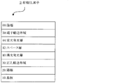
- FIG. 2 is a schematic view showing the layer structure of another embodiment of the organic EL device of the present invention.
- the organic EL element 2 is an example of a hybrid type organic EL element in which a phosphorescent light emitting layer and a fluorescent light emitting layer are laminated.
- the organic EL element 2 has the same configuration as the organic EL element 1 except that a space layer 42 and a fluorescent light emitting layer 44 are formed between the phosphorescent light emitting layer 40 and the electron transport zone 50.
- the excitons formed in the phosphorescent light emitting layer 40 are not diffused into the fluorescent light emitting layer 44, so that a space layer 42 is provided between the fluorescent light emitting layer 44 and the phosphorescent light emitting layer 40. May be provided. Since the material of the present invention has a large triplet energy, it can function as a space layer.
- a white light emitting organic EL element can be obtained by setting the phosphorescent light emitting layer to emit yellow light and the fluorescent light emitting layer to blue light emitting layer.
- the phosphorescent light-emitting layer and the fluorescent light-emitting layer are formed one by one.
- the present invention is not limited to this, and two or more layers may be formed, and can be appropriately set according to the application such as lighting and display device.
- a full color light emitting device is formed using a white light emitting element and a color filter
- a plurality of wavelength regions such as red, green, blue (RGB), red, green, blue, yellow (RGBY) are used from the viewpoint of color rendering. In some cases, it may be preferable to include luminescence.
- the organic EL element of the present invention can employ various known configurations. Further, light emission of the light emitting layer can be taken out from the anode side, the cathode side, or both sides.
- the configuration other than the layer using the organic EL element material of the present invention described above is not particularly limited, and a known material or the like can be used.
- a known material or the like can be used.
- the layer of the element of Embodiment 1 is demonstrated easily, the material applied to the organic EL element of this invention is not limited to the following.
- a glass plate, a polymer plate or the like can be used as the substrate.
- the glass plate include soda lime glass, barium / strontium-containing glass, lead glass, aluminosilicate glass, borosilicate glass, barium borosilicate glass, and quartz.
- the polymer plate include polycarbonate, acrylic, polyethylene terephthalate, polyether sulfone, and polysulfone.
- the anode is made of, for example, a conductive material, and a conductive material having a work function larger than 4 eV is suitable.
- the conductive material include carbon, aluminum, vanadium, iron, cobalt, nickel, tungsten, silver, gold, platinum, palladium, and their alloys, ITO substrate, tin oxide used for NESA substrate, indium oxide, and the like.
- examples thereof include metal oxides and organic conductive resins such as polythiophene and polypyrrole.
- the anode may be formed with a layer structure of two or more layers if necessary.
- the cathode is made of, for example, a conductive material, and a conductive material having a work function smaller than 4 eV is suitable.
- the conductive material include, but are not limited to, magnesium, calcium, tin, lead, titanium, yttrium, lithium, ruthenium, manganese, aluminum, lithium fluoride, and alloys thereof.
- the alloy include magnesium / silver, magnesium / indium, lithium / aluminum, and the like, but are not limited thereto.
- the ratio of the alloy is controlled by the temperature of the vapor deposition source, the atmosphere, the degree of vacuum, etc., and is selected to an appropriate ratio.
- the cathode may be formed with a layer structure of two or more layers, and the cathode can be produced by forming a thin film from the conductive material by a method such as vapor deposition or sputtering.
- the transmittance of the cathode for light emission is preferably greater than 10%.
- the sheet resistance as the cathode is preferably several hundred ⁇ / ⁇ or less, and the film thickness is usually 10 nm to 1 ⁇ m, preferably 50 to 200 nm.
- the phosphorescent light emitting layer is formed of a material other than the organic EL element layer material of the present invention
- a known material can be used as the material of the phosphorescent light emitting layer.
- Japanese Patent Application No. 2005-517938 may be referred to.
- the organic EL device of the present invention may have a fluorescent light emitting layer like the device shown in FIG. A known material can be used for the fluorescent light emitting layer.
- the light emitting layer may be a double host (also referred to as a host / cohost). Specifically, the carrier balance in the light emitting layer may be adjusted by combining an electron transporting host and a hole transporting host in the light emitting layer. Moreover, it is good also as a double dopant.
- each dopant emits light by adding two or more dopant materials having a high quantum yield. For example, a yellow light emitting layer may be realized by co-evaporating a host, a red dopant, and a green dopant.
- the light emitting layer may be a single layer or a laminated structure. When the light emitting layer is stacked, the recombination region can be concentrated on the light emitting layer interface by accumulating electrons and holes at the light emitting layer interface. This improves the quantum efficiency.
- the hole injection / transport layer is a layer that assists hole injection into the light emitting layer and transports it to the light emitting region, and has a high hole mobility and a small ionization energy of usually 5.6 eV or less.
- As the material for the hole injection / transport layer a material that transports holes to the light emitting layer with lower electric field strength is preferable. Further, when an electric field is applied with a hole mobility of, for example, 10 4 to 10 6 V / cm, At least 10 ⁇ 4 cm 2 / V ⁇ sec is preferable.
- the material for the hole injection / transport layer include triazole derivatives (see US Pat. No. 3,112,197) and oxadiazole derivatives (see US Pat. No. 3,189,447). ), Imidazole derivatives (see JP-B-37-16096, etc.), polyarylalkane derivatives (US Pat. Nos. 3,615,402, 3,820,989, 3,542,544) Nos. 45-555, 51-10983, 51-93224, 55-17105, 56-4148, 55-108667, 55-156953, 56-36656, etc.), pyrazoline derivatives and pyrazolone derivatives (US Pat. No. 3,180,729, No. 4) Nos.
- Gazette 55-52063, 55-52064, 55-46760, 57-11350, 57- No. 148749, JP-A-2-311591, etc.), stilbene derivatives (JP-A Nos. 61-210363, 61-228451, 61-14642, 61-72255, etc.) 62-47646, 62-36684, 62-10652, 62-30255, 60-93455, 60-94462, 60-174749, 60 -175052, etc.), silazane derivatives (US Pat. No. 4,950,950), polysilanes (JP-A-2-204996), aniline copolymers (JP-A-2-282263) Etc.
- inorganic compounds such as p-type Si and p-type SiC can also be used as the hole injection material.
- a cross-linkable material can be used as the material of the hole injection / transport layer.
- a cross-linkable hole injection / transport layer for example, Chem. Mater. 2008, 20, 413-422, Chem. Mater. Examples include a layer obtained by insolubilizing a cross-linking material such as 2011, 23 (3), 658-681, WO2008108430, WO2009102027, WO2009123269, WO2010016555, WO2010018813 by heat, light or the like.
- the electron injection / transport layer is a layer that assists the injection of electrons into the light emitting layer and transports it to the light emitting region, and has a high electron mobility.
- an electrode for example, a cathode
- the electron injecting / transporting layer is appropriately selected with a film thickness of several nm to several ⁇ m.
- the electron mobility is preferably at least 10 ⁇ 5 cm 2 / Vs or more when an electric field of V / cm is applied.
- an aromatic heterocyclic compound containing one or more heteroatoms in the molecule is preferably used, and a nitrogen-containing ring derivative is particularly preferable.
- a nitrogen-containing ring derivative a heteroaromatic hydrocarbon ring compound having a nitrogen-containing 6-membered ring or 5-membered ring skeleton, or a hetero-fused aromatic ring compound having a nitrogen-containing 6-membered ring or 5-membered ring skeleton is preferable. Examples thereof include compounds containing a pyridine ring, pyrimidine ring, triazine ring, benzimidazole ring, phenanthroline ring, quinazoline ring and the like in the skeleton.
- an organic layer having semiconductivity may be formed by doping (n) with a donor material and doping (p) with an acceptor material.
- N doping is to dope a metal such as Li or Cs into an electron transporting material
- P doping is to dope an acceptor material such as F4TCNQ into a hole transporting material ( For example, refer patent 3695714).
- one or more electron transport layers are preferably contained, and at least one of the electron transport layers preferably contains the compound of the present invention.
- an organic EL element with a low driving voltage can be realized.
- two or more electron transport layers are included, at least one of the electron transport layers includes the compound of the present invention, and the same or another electron transport layer includes the above-described nitrogen-containing six-membered ring or It is preferable to include a heteroaromatic hydrocarbon ring compound having a 5-membered ring skeleton, or a hetero-fused aromatic ring compound having a nitrogen-containing 6-membered ring or a 5-membered ring skeleton. Thereby, since an organic EL element with good electron injection can be realized, the driving voltage can be reduced.
- the organic EL device of the present invention preferably has at least one of an electron donating dopant and an organometallic complex in an interface region between the cathode and the organic thin film layer. According to such a configuration, it is possible to improve the light emission luminance and extend the life of the organic EL element.
- the electron donating dopant include at least one selected from alkali metals, alkali metal compounds, alkaline earth metals, alkaline earth metal compounds, rare earth metals, rare earth metal compounds, and the like.
- the organometallic complex include at least one selected from an organometallic complex containing an alkali metal, an organometallic complex containing an alkaline earth metal, an organometallic complex containing a rare earth metal, and the like.
- alkali metal examples include lithium (Li) (work function: 2.93 eV), sodium (Na) (work function: 2.36 eV), potassium (K) (work function: 2.28 eV), rubidium (Rb) (work Function: 2.16 eV), cesium (Cs) (work function: 1.95 eV) and the like, and those having a work function of 2.9 eV or less are particularly preferable.
- K, Rb, and Cs are preferred, Rb or Cs is more preferred, and Cs is most preferred.
- alkaline earth metal examples include calcium (Ca) (work function: 2.9 eV), strontium (Sr) (work function: 2.0 eV to 2.5 eV), barium (Ba) (work function: 2.52 eV).
- a work function of 2.9 eV or less is particularly preferable.
- the rare earth metal examples include scandium (Sc), yttrium (Y), cerium (Ce), terbium (Tb), ytterbium (Yb) and the like, and those having a work function of 2.9 eV or less are particularly preferable.
- preferred metals are particularly high in reducing ability, and by adding a relatively small amount to the electron injection region, it is possible to improve the light emission luminance and extend the life of the organic EL element.
- alkali metal compound examples include lithium oxide (Li 2 O), cesium oxide (Cs 2 O), alkali oxides such as potassium oxide (K 2 O), lithium fluoride (LiF), sodium fluoride (NaF), fluorine.
- alkali halides such as cesium fluoride (CsF) and potassium fluoride (KF), and lithium fluoride (LiF), lithium oxide (Li 2 O), and sodium fluoride (NaF) are preferable.
- alkaline earth metal compound examples include barium oxide (BaO), strontium oxide (SrO), calcium oxide (CaO), and barium strontium oxide (Ba x Sr 1-x O) (0 ⁇ x ⁇ 1), Examples thereof include barium calcium oxide (Ba x Ca 1-x O) (0 ⁇ x ⁇ 1), and BaO, SrO, and CaO are preferable.
- the rare earth metal compound ytterbium fluoride (YbF 3), scandium fluoride (ScF 3), scandium oxide (ScO 3), yttrium oxide (Y 2 O 3), cerium oxide (Ce 2 O 3), gadolinium fluoride (GdF 3), such as terbium fluoride (TbF 3) can be mentioned, YbF 3, ScF 3, TbF 3 are preferable.
- the organometallic complex is not particularly limited as long as it contains at least one of an alkali metal ion, an alkaline earth metal ion, and a rare earth metal ion as a metal ion as described above.
- the ligand includes quinolinol, benzoquinolinol, acridinol, phenanthridinol, hydroxyphenyl oxazole, hydroxyphenyl thiazole, hydroxydiaryl oxadiazole, hydroxydiaryl thiadiazole, hydroxyphenyl pyridine, hydroxyphenyl benzimidazole, hydroxybenzotriazole, Hydroxyfulborane, bipyridyl, phenanthroline, phthalocyanine, porphyrin, cyclopentadiene, ⁇ -diketones, azomethines, and derivatives thereof are preferred, but not limited thereto.
- the addition form of the electron donating dopant and the organometallic complex is preferably formed in a layered or island shape in the interface region.
- a forming method while depositing at least one of an electron donating dopant and an organometallic complex by a resistance heating vapor deposition method, an organic material as a light emitting material or an electron injection material for forming an interface region is simultaneously deposited, and an electron is deposited in the organic material.
- a method of dispersing at least one of a donor dopant and an organometallic complex reducing dopant is preferable.
- the dispersion concentration is usually organic substance: electron donating dopant and / or organometallic complex in a molar ratio of 100: 1 to 1: 100, preferably 5: 1 to 1: 5.
- At least one of the electron donating dopant and the organometallic complex is formed in a layered form
- at least one of the electron donating dopant and the organometallic complex is formed.
- These are vapor-deposited by a resistance heating vapor deposition method alone, preferably with a layer thickness of 0.1 nm to 15 nm.
- an electron donating dopant and an organometallic complex is formed in an island shape
- a light emitting material or an electron injecting material which is an organic layer at the interface is formed in an island shape, and then the electron donating dopant and the organometallic complex are formed. At least one of them is vapor-deposited by a resistance heating vapor deposition method, preferably with an island thickness of 0.05 nm to 1 nm.
- the ratio of at least one of the main component (light-emitting material or electron injection material), the electron-donating dopant, and the organometallic complex is, as a molar ratio, the main component: the electron-donating dopant.
- / or organometallic complex 5: 1 to 1: 5, preferably 2: 1 to 1: 2.
- each layer of the organic EL device of the present invention a known method such as a dry film forming method such as vacuum deposition, sputtering, plasma, or ion plating, or a wet film forming method such as spin coating, dipping, or flow coating is applied. be able to.
- the thickness of each layer is not particularly limited, but must be set to an appropriate thickness. If the film thickness is too thick, a large applied voltage is required to obtain a constant light output, resulting in poor efficiency. If the film thickness is too thin, pinholes and the like are generated, and sufficient light emission luminance cannot be obtained even when an electric field is applied.
- the normal film thickness is suitably in the range of 5 nm to 10 ⁇ m, but more preferably in the range of 10 nm to 0.2 ⁇ m.
- the reaction mixture was allowed to cool to room temperature, filtered through celite, the solvent was distilled off under reduced pressure, the residue was purified by silica gel column chromatography, recrystallized, and 2.1 g of compound 8 (yield 45%) )Obtained.
- the molecular weight of the obtained solid was measured by FD-mass spectrum to be 779.
- reaction mixture was allowed to cool to room temperature, filtered through celite, the solvent was distilled off under reduced pressure, the residue was purified by silica gel column chromatography, and recrystallized to obtain 2.5 g of intermediate E (yield). 66%). It was 561 when molecular weight was measured by FD-mass spectrum about the obtained solid.
- reaction mixture was allowed to cool to room temperature, filtered through celite, the solvent was distilled off under reduced pressure, the residue was purified by silica gel column chromatography and purified by recrystallization, and 1.5 g (yield 51%) of compound 10 was obtained. Obtained. The molecular weight of the obtained solid was measured by FD-mass spectrum and found to be 728.
- triplet energies of the above compounds 1 to 10 were measured. Triplet energy was measured using F-4500 (Hitachi).
- the sample for phosphorescence measurement placed in the quartz cell was cooled to 77 (K), and the phosphorescence measurement sample was irradiated with excitation light, and the phosphorescence intensity was measured while changing the wavelength. Is the phosphorescence intensity, and the horizontal axis is the wavelength.
- a tangent line was drawn with respect to the rising edge of the phosphorescence spectrum on the short wavelength side, and the wavelength value ⁇ ph (nm) at the intersection of the tangent line and the horizontal axis was obtained.
- the tangent to the rising edge on the short wavelength side of the phosphorescence spectrum is drawn as follows. When moving on the spectrum curve from the short wavelength side of the phosphorescence spectrum to the maximum value on the shortest wavelength side among the maximum values of the spectrum, tangents at each point on the curve are considered toward the long wavelength side. The slope of this tangent line increases as the curve rises (that is, as the vertical axis increases).
- the tangent drawn at the point where the slope value takes the maximum value is taken as the tangent to the rising edge of the phosphorescence spectrum on the short wavelength side. Note that the maximum point having a peak intensity of 10% or less of the maximum peak intensity of the spectrum is not included in the above-mentioned maximum value on the shortest wavelength side, but has the maximum slope value closest to the maximum value on the shortest wavelength side.
- the tangent drawn at the point where the value is taken is taken as the tangent to the rising edge of the phosphorescence spectrum on the short wavelength side. Table 1 shows triplet energies of compounds 1 to 10 and materials 4 and 6 described later which are phosphorescent materials.
- Example 1 A 25 mm ⁇ 75 mm ⁇ 1.1 mm glass substrate with an ITO transparent electrode (manufactured by Geomatic) was subjected to ultrasonic cleaning for 5 minutes in isopropyl alcohol, and further subjected to UV (Ultraviolet) ozone cleaning for 30 minutes. .
- the ITO film thickness was 70 nm.
- the cleaned glass substrate with a transparent electrode is attached to a substrate holder of a vacuum deposition apparatus, and the material 1 is 5 nm thick so that the transparent electrode is covered on the surface of the glass substrate on which the transparent electrode line is formed.
- the hole injection layer was obtained by vapor deposition.
- the material 2 was vapor-deposited with a thickness of 65 nm on this film to obtain a first hole transport layer.
- the material 3 was vapor-deposited with a thickness of 10 nm on this film to obtain a second hole transport layer.
- the compound 1 obtained in Synthesis Example 1 as a phosphorescent host material and the material 4 (facial body) which is a phosphorescent material were co-evaporated at a thickness of 25 nm to obtain a phosphorescent layer.
- the concentration of Compound 1 in the phosphorescent light emitting layer was 90% by mass, and the concentration of Material 4 was 10% by mass.
- the material 5 was vapor-deposited with a thickness of 35 nm on the phosphorescent light emitting layer to obtain an electron transport layer. Further, 1 nm thick LiF and 80 nm thick metal Al were sequentially laminated to obtain a cathode. Note that LiF, which is an electron injecting electrode, was formed at a rate of 0.1 ⁇ / min to produce an organic EL element.
- Examples 2-8 An organic EL device was prepared and evaluated in the same manner as in Example 1 except that the compound shown in Table 2 was used instead of Compound 1 as the phosphorescent host material. The results are shown in Table 2.
- Comparative Examples 1 and 2 An organic EL device was prepared and evaluated in the same manner as in Example 1 except that the following comparative compound 1 or 2 shown in Table 2 was used instead of compound 1 as the phosphorescent host material. The results are shown in Table 2.
- Example 9 A 25 mm ⁇ 75 mm ⁇ 1.1 mm glass substrate with an ITO transparent electrode (manufactured by Geomatic) was subjected to ultrasonic cleaning for 5 minutes in isopropyl alcohol, and further subjected to UV (Ultraviolet) ozone cleaning for 30 minutes. .
- the ITO film thickness was 130 nm.
- the cleaned glass substrate with the transparent electrode is attached to the substrate holder of the vacuum evaporation apparatus, and the material 1 is first thickened so that the transparent electrode is covered on the surface of the glass substrate on which the transparent electrode line is formed.
- the hole injection layer was obtained by vapor deposition at a thickness of 5 nm.
- the material 7 was vapor-deposited with a thickness of 50 nm on this film to obtain a first hole transport layer.
- the material 8 was vapor-deposited with a thickness of 60 nm on this film to obtain a second hole transport layer.
- the compound 4 obtained in Synthesis Example 4 as a phosphorescent host material and the material 6 (facial body) which is a phosphorescent material were co-evaporated at a thickness of 45 nm to obtain a phosphorescent layer.
- the concentration of Compound 4 in the phosphorescent light emitting layer was 92% by mass, and the concentration of Material 6 was 8% by mass.
- the material 9 was vapor-deposited with a thickness of 30 nm on the phosphorescent light emitting layer to obtain an electron transport layer. Further, 1 nm thick LiF and 80 nm thick metal Al were sequentially laminated to obtain a cathode. Note that LiF, which is an electron injecting electrode, was formed at a rate of 0.1 ⁇ / min to produce an organic EL element.
- Examples 10 and 11 An organic EL device was prepared and evaluated in the same manner as in Example 9 except that the compound shown in Table 3 was used instead of the compound 4 as the phosphorescent host material. The results are shown in Table 3.
- Comparative Examples 3 and 4 An organic EL device was prepared and evaluated in the same manner as in Example 9 except that the compound shown in Table 3 was used instead of the compound 4 as the phosphorescent host material. The results are shown in Table 3.
- the compound of the present invention can be used for organic EL devices, organic EL displays, lighting, organic semiconductors, organic solar cells, and the like.
- the organic EL device of the present invention can be used for a flat light emitter such as a flat panel display of a wall-mounted television, a light source such as a copying machine, a printer, a backlight of a liquid crystal display or instruments, a display board, a marker lamp, and the like.
Landscapes
- Chemical & Material Sciences (AREA)
- Organic Chemistry (AREA)
- Engineering & Computer Science (AREA)
- Materials Engineering (AREA)
- Physics & Mathematics (AREA)
- Spectroscopy & Molecular Physics (AREA)
- Optics & Photonics (AREA)
- Electroluminescent Light Sources (AREA)
- Nitrogen Condensed Heterocyclic Rings (AREA)
- Heterocyclic Carbon Compounds Containing A Hetero Ring Having Oxygen Or Sulfur (AREA)
Abstract
Priority Applications (2)
| Application Number | Priority Date | Filing Date | Title |
|---|---|---|---|
| US14/371,399 US9685614B2 (en) | 2012-01-10 | 2012-12-28 | Material for organic electroluminescent element, and element using same |
| KR1020147018754A KR20140107398A (ko) | 2012-01-10 | 2012-12-28 | 유기 전계 발광 소자용 재료 및 그것을 사용한 소자 |
Applications Claiming Priority (2)
| Application Number | Priority Date | Filing Date | Title |
|---|---|---|---|
| JP2012-001815 | 2012-01-10 | ||
| JP2012001815 | 2012-01-10 |
Publications (1)
| Publication Number | Publication Date |
|---|---|
| WO2013105206A1 true WO2013105206A1 (fr) | 2013-07-18 |
Family
ID=48781185
Family Applications (1)
| Application Number | Title | Priority Date | Filing Date |
|---|---|---|---|
| PCT/JP2012/008442 Ceased WO2013105206A1 (fr) | 2012-01-10 | 2012-12-28 | Matériau pour élément électroluminescent organique, et élément comprenant ce matériau |
Country Status (5)
| Country | Link |
|---|---|
| US (1) | US9685614B2 (fr) |
| JP (1) | JPWO2013105206A1 (fr) |
| KR (1) | KR20140107398A (fr) |
| TW (1) | TW201348228A (fr) |
| WO (1) | WO2013105206A1 (fr) |
Cited By (7)
| Publication number | Priority date | Publication date | Assignee | Title |
|---|---|---|---|---|
| WO2013191177A1 (fr) * | 2012-06-18 | 2013-12-27 | 東ソー株式会社 | Composé azine cyclique, son procédé de fabrication, et élément électroluminescent organique le contenant |
| US20140142301A1 (en) * | 2012-11-20 | 2014-05-22 | Samsung Display Co., Ltd. | Organic electroluminescence material comprising azacarbazole derivative and organic electrolumunescence device having the same |
| WO2014081206A1 (fr) * | 2012-11-21 | 2014-05-30 | Rohm And Haas Electronic Materials Korea Ltd. | Nouveaux composés organiques électroluminescents et dispositif organique électroluminescent les contenant |
| JP2015021008A (ja) * | 2013-07-16 | 2015-02-02 | ユニバーサル ディスプレイ コーポレイション | 含窒素ヘテロポリ芳香族部分を電子アクセプターとして含むドナーアクセプター化合物 |
| WO2015063046A1 (fr) | 2013-10-31 | 2015-05-07 | Basf Se | Azadibenzothiophènes pour applications électroniques |
| US9203036B2 (en) | 2012-02-03 | 2015-12-01 | Idemitsu Kosan Co., Ltd. | Carbazole compound, material for organic electroluminescence device and organic electroluminescence device |
| US10153437B2 (en) | 2015-05-12 | 2018-12-11 | Semiconductor Energy Laboratory Co., Ltd. | Compound, light-emitting element, light-emitting device, electronic device, and lighting device |
Families Citing this family (14)
| Publication number | Priority date | Publication date | Assignee | Title |
|---|---|---|---|---|
| US9755159B2 (en) | 2014-01-23 | 2017-09-05 | Universal Display Corporation | Organic materials for OLEDs |
| KR102283293B1 (ko) * | 2014-12-26 | 2021-07-28 | 솔루스첨단소재 주식회사 | 유기 화합물 및 이를 포함하는 유기 전계 발광 소자 |
| EP3150604B1 (fr) | 2015-10-01 | 2021-07-14 | Idemitsu Kosan Co., Ltd. | Groupes benzimidazolo [1,2-a] benzimidazoles portant des benzimidazolo [1,2-a] benzimidazolyles, groupes carbazolyles, groupes benzofuranes ou benzothiophènes pour diodes électroluminescentes organiques |
| US20180269407A1 (en) | 2015-10-01 | 2018-09-20 | Idemitsu Kosan Co., Ltd. | Benzimidazolo[1,2-a]benzimidazole carrying triazine groups for organic light emitting diodes |
| EP3150606B1 (fr) | 2015-10-01 | 2019-08-14 | Idemitsu Kosan Co., Ltd. | Benzimidazolo[1,2-a]benzimidazoles avec des groupements benzofurane ou benzothiophène pour des diodes émittant de la lumière |
| WO2017056053A1 (fr) | 2015-10-01 | 2017-04-06 | Idemitsu Kosan Co., Ltd. | Groupes benzimidazolo[1,2-a]benzimidazolyle, groupes carbazolyle, groupes benzofuranne ou groupes benzothiophène portant un composé benzimidazolo[1,2-a] benzimidazole pour diodes électroluminescentes organiques |
| KR20180079328A (ko) | 2015-11-04 | 2018-07-10 | 이데미쓰 고산 가부시키가이샤 | 벤즈이미다졸 축합 헤테로아릴 |
| WO2017093958A1 (fr) | 2015-12-04 | 2017-06-08 | Idemitsu Kosan Co., Ltd. | Dérivés benzimidazolo[1,2-a]benzimidazole pour des diodes électroluminescentes organiques |
| US20180370981A1 (en) | 2015-12-21 | 2018-12-27 | Idemitsu Kosan Co., Ltd. | Hetero-condensed phenylquinazolines and their use in electronic devices |
| WO2017221999A1 (fr) | 2016-06-22 | 2017-12-28 | Idemitsu Kosan Co., Ltd. | Benzofuro- et benzothiénoquinolines à substitution spécifique pour diodes électroluminescentes organiques |
| US11279709B2 (en) | 2016-09-05 | 2022-03-22 | Idemitsu Kosan Co., Ltd. | Specifically substituted aza-dibenzofurans and aza-dibenzothiophenes for organic electronic devices |
| EP3466954A1 (fr) | 2017-10-04 | 2019-04-10 | Idemitsu Kosan Co., Ltd. | Phénylquinazolines condensées et pontées avec un hétéroatome |
| EP3604477A1 (fr) | 2018-07-30 | 2020-02-05 | Idemitsu Kosan Co., Ltd. | Composé polycyclique, dispositif électroluminescent organique et dispositif électronique |
| EP3608319A1 (fr) | 2018-08-07 | 2020-02-12 | Idemitsu Kosan Co., Ltd. | Azacycles condensés comme dispositif électroluminescent organique et matériaux à utiliser en son sein |
Citations (4)
| Publication number | Priority date | Publication date | Assignee | Title |
|---|---|---|---|---|
| JP2011084531A (ja) * | 2009-10-19 | 2011-04-28 | Konica Minolta Holdings Inc | 有機エレクトロルミネッセンス素子用材料、有機エレクトロルミネッセンス素子、照明装置及び表示装置 |
| WO2011137072A1 (fr) * | 2010-04-26 | 2011-11-03 | Universal Display Corporation | Composés contenant un bicarbazole pour oled |
| WO2012023947A1 (fr) * | 2010-08-20 | 2012-02-23 | Universal Display Corporation | Composés de bicarbazole pour dispositifs électroluminescents organiques (oled) |
| WO2012108389A1 (fr) * | 2011-02-07 | 2012-08-16 | 出光興産株式会社 | Dérivé de bis-carbazole ainsi qu'élément électroluminescent organique mettant en oeuvre celui-ci |
Family Cites Families (6)
| Publication number | Priority date | Publication date | Assignee | Title |
|---|---|---|---|---|
| US7279704B2 (en) * | 2004-05-18 | 2007-10-09 | The University Of Southern California | Complexes with tridentate ligands |
| KR101847222B1 (ko) * | 2009-10-23 | 2018-04-09 | 호도가야 가가쿠 고교 가부시키가이샤 | 유기 일렉트로 루미네센스 소자 |
| KR101506999B1 (ko) * | 2009-11-03 | 2015-03-31 | 제일모직 주식회사 | 유기광전소자용 화합물 및 이를 포함하는 유기광전소자 |
| US8828561B2 (en) | 2009-11-03 | 2014-09-09 | Cheil Industries, Inc. | Compound for organic photoelectric device and organic photoelectric device including the same |
| JP5261611B2 (ja) | 2010-03-31 | 2013-08-14 | 出光興産株式会社 | 有機エレクトロルミネッセンス素子用材料及びそれを用いた有機エレクトロルミネッセンス素子 |
| KR20110122051A (ko) | 2010-05-03 | 2011-11-09 | 제일모직주식회사 | 유기광전소자용 화합물 및 이를 포함하는 유기광전소자 |
-
2012
- 2012-12-28 US US14/371,399 patent/US9685614B2/en active Active
- 2012-12-28 KR KR1020147018754A patent/KR20140107398A/ko not_active Ceased
- 2012-12-28 JP JP2013553115A patent/JPWO2013105206A1/ja active Pending
- 2012-12-28 WO PCT/JP2012/008442 patent/WO2013105206A1/fr not_active Ceased
-
2013
- 2013-01-03 TW TW102100103A patent/TW201348228A/zh unknown
Patent Citations (4)
| Publication number | Priority date | Publication date | Assignee | Title |
|---|---|---|---|---|
| JP2011084531A (ja) * | 2009-10-19 | 2011-04-28 | Konica Minolta Holdings Inc | 有機エレクトロルミネッセンス素子用材料、有機エレクトロルミネッセンス素子、照明装置及び表示装置 |
| WO2011137072A1 (fr) * | 2010-04-26 | 2011-11-03 | Universal Display Corporation | Composés contenant un bicarbazole pour oled |
| WO2012023947A1 (fr) * | 2010-08-20 | 2012-02-23 | Universal Display Corporation | Composés de bicarbazole pour dispositifs électroluminescents organiques (oled) |
| WO2012108389A1 (fr) * | 2011-02-07 | 2012-08-16 | 出光興産株式会社 | Dérivé de bis-carbazole ainsi qu'élément électroluminescent organique mettant en oeuvre celui-ci |
Cited By (10)
| Publication number | Priority date | Publication date | Assignee | Title |
|---|---|---|---|---|
| US9203036B2 (en) | 2012-02-03 | 2015-12-01 | Idemitsu Kosan Co., Ltd. | Carbazole compound, material for organic electroluminescence device and organic electroluminescence device |
| WO2013191177A1 (fr) * | 2012-06-18 | 2013-12-27 | 東ソー株式会社 | Composé azine cyclique, son procédé de fabrication, et élément électroluminescent organique le contenant |
| US20140142301A1 (en) * | 2012-11-20 | 2014-05-22 | Samsung Display Co., Ltd. | Organic electroluminescence material comprising azacarbazole derivative and organic electrolumunescence device having the same |
| US9318711B2 (en) * | 2012-11-20 | 2016-04-19 | Samsung Display Co., Ltd. | Organic electroluminescence materials comprising substituted carbazoles and organic electroluminescence devices having the same |
| WO2014081206A1 (fr) * | 2012-11-21 | 2014-05-30 | Rohm And Haas Electronic Materials Korea Ltd. | Nouveaux composés organiques électroluminescents et dispositif organique électroluminescent les contenant |
| CN104781253A (zh) * | 2012-11-21 | 2015-07-15 | 罗门哈斯电子材料韩国有限公司 | 新颖有机电致发光化合物和含有所述化合物的有机电致发光装置 |
| CN104781253B (zh) * | 2012-11-21 | 2018-09-07 | 罗门哈斯电子材料韩国有限公司 | 新颖有机电致发光化合物和含有所述化合物的有机电致发光装置 |
| JP2015021008A (ja) * | 2013-07-16 | 2015-02-02 | ユニバーサル ディスプレイ コーポレイション | 含窒素ヘテロポリ芳香族部分を電子アクセプターとして含むドナーアクセプター化合物 |
| WO2015063046A1 (fr) | 2013-10-31 | 2015-05-07 | Basf Se | Azadibenzothiophènes pour applications électroniques |
| US10153437B2 (en) | 2015-05-12 | 2018-12-11 | Semiconductor Energy Laboratory Co., Ltd. | Compound, light-emitting element, light-emitting device, electronic device, and lighting device |
Also Published As
| Publication number | Publication date |
|---|---|
| US9685614B2 (en) | 2017-06-20 |
| TW201348228A (zh) | 2013-12-01 |
| KR20140107398A (ko) | 2014-09-04 |
| JPWO2013105206A1 (ja) | 2015-05-11 |
| US20140367667A1 (en) | 2014-12-18 |
Similar Documents
| Publication | Publication Date | Title |
|---|---|---|
| JP6012611B2 (ja) | 有機エレクトロルミネッセンス素子用材料及びそれを用いた有機エレクトロルミネッセンス素子 | |
| JP6148982B2 (ja) | 含窒素へテロ芳香族環化合物 | |
| JP6212391B2 (ja) | 有機エレクトロルミネッセンス素子 | |
| US9685614B2 (en) | Material for organic electroluminescent element, and element using same | |
| WO2013102992A1 (fr) | Matériau pour élément organique électroluminescent et élément utilisant ce matériau | |
| JP6196554B2 (ja) | 有機エレクトロルミネッセンス素子用材料及びそれを用いた有機エレクトロルミネッセンス素子 | |
| JP6220341B2 (ja) | ラダー化合物、及びそれを用いた有機エレクトロルミネッセンス素子 | |
| CN102471320A (zh) | 含芴芳香族化合物、有机电致发光元件用材料及使用其的有机电致发光元件 | |
| WO2013175746A1 (fr) | Élément électroluminescent organique | |
| JPWO2013069242A1 (ja) | 有機エレクトロルミネッセンス素子用材料及びそれを用いた有機エレクトロルミネッセンス素子 | |
| WO2013179645A1 (fr) | Matériau d'élément électroluminescent organique, et élément électroluminescent organique l'utilisant | |
| KR20120125368A (ko) | 유기 전계 발광 소자 | |
| JP2013108015A (ja) | 有機エレクトロルミネッセンス素子用材料 | |
| JPWO2013108589A1 (ja) | 新規化合物、有機エレクトロルミネッセンス素子用材料及び有機エレクトロルミネッセンス素子 | |
| JP6031302B2 (ja) | ヘテロ芳香族化合物及びそれを用いた有機エレクトロルミネッセンス素子 | |
| US9496508B2 (en) | Material for organic electroluminescent element and organic electroluminescent element using same | |
| WO2014112359A1 (fr) | Élément électroluminescent organique |
Legal Events
| Date | Code | Title | Description |
|---|---|---|---|
| 121 | Ep: the epo has been informed by wipo that ep was designated in this application |
Ref document number: 12864876 Country of ref document: EP Kind code of ref document: A1 |
|
| ENP | Entry into the national phase |
Ref document number: 2013553115 Country of ref document: JP Kind code of ref document: A |
|
| ENP | Entry into the national phase |
Ref document number: 20147018754 Country of ref document: KR Kind code of ref document: A |
|
| WWE | Wipo information: entry into national phase |
Ref document number: 14371399 Country of ref document: US |
|
| NENP | Non-entry into the national phase |
Ref country code: DE |
|
| 122 | Ep: pct application non-entry in european phase |
Ref document number: 12864876 Country of ref document: EP Kind code of ref document: A1 |