WO2013105337A1 - Appareil formant contenant - Google Patents
Appareil formant contenant Download PDFInfo
- Publication number
- WO2013105337A1 WO2013105337A1 PCT/JP2012/079628 JP2012079628W WO2013105337A1 WO 2013105337 A1 WO2013105337 A1 WO 2013105337A1 JP 2012079628 W JP2012079628 W JP 2012079628W WO 2013105337 A1 WO2013105337 A1 WO 2013105337A1
- Authority
- WO
- WIPO (PCT)
- Prior art keywords
- container
- container housing
- frame
- longitudinal
- housing
- Prior art date
- Legal status (The legal status is an assumption and is not a legal conclusion. Google has not performed a legal analysis and makes no representation as to the accuracy of the status listed.)
- Ceased
Links
Images







Classifications
-
- E—FIXED CONSTRUCTIONS
- E04—BUILDING
- E04H—BUILDINGS OR LIKE STRUCTURES FOR PARTICULAR PURPOSES; SWIMMING OR SPLASH BATHS OR POOLS; MASTS; FENCING; TENTS OR CANOPIES, IN GENERAL
- E04H5/00—Buildings or groups of buildings for industrial or agricultural purposes
- E04H5/02—Buildings or groups of buildings for industrial purposes, e.g. for power-plants or factories
Definitions
- the present invention relates to a container apparatus, and more particularly to a container apparatus provided with a plurality of apparatuses that are installed inside a container housing and each form part of a production line of factory equipment.
- the factory When starting up factory equipment, the factory itself may require a certain level of accuracy. For example, when performing tape production by roll-to-roll, it is necessary to adjust the height of the roll core among a plurality of devices having a roll core in order to accurately flow the tape from roll to roll. It is necessary to adjust the roll core horizontally. If these adjustments are not performed satisfactorily, the film fed from the roll may be distorted, or may be defective due to winding deviation, wrinkles, breakage, and the like. In general, the height and horizontal accuracy of the roll core are adjusted based on the distance from the floor surface to the roll core, and the distance between the roll core and the floor surface in each apparatus is set for each apparatus. It is assumed that the floor of the factory is the same height.
- the floor of the factory is required to have a strict plane accuracy (for example, unevenness of about 30 mm on a 50 m square floor. Can even be a problem). It is often difficult to meet such strict plane accuracy in all countries, and it was common to fine tune the location and angle of installation on site, but this work requires a great deal of effort. And needed time.
- the present invention has been made to solve such problems in the prior art, and an object of the present invention is to provide a container device that can transport and move factory equipment as it is. It is another object of the present invention to provide a container device that facilitates assembly and maintenance of factory equipment. Furthermore, it aims at improving a plane precision in the floor surface of such a container apparatus.
- a rectangular container housing and a plurality of devices installed inside the container housing along a longitudinal direction of the container housing each of the plurality of devices at least partially includes the container. It is fixed to at least one of a frame of the housing or a plate-like member fixed to the frame and defining the inner bottom of the container housing, and the frame of the container housing has at least an exterior of the container housing
- a rectangular bottom frame is formed, and the bottom frame includes two longitudinal beams extending in parallel along the longitudinal direction of the container housing, and the container housing so as to connect the two longitudinal beams to each other.
- a container device is provided which is defined by two horizontal beams extending in parallel along the width direction.
- the skeleton frame defining the bottom frame includes the rigid longitudinal beam and the horizontal beam, by fixing the plate-like member to the rigid skeleton frame, a predetermined plane Accuracy can be obtained.
- this bottom frame can be used to form a flat surface with excellent flatness accuracy by simply adjusting the height of a part of the bottom frame. Can do. Furthermore, since the plate-like member is fixed to such a rigid skeleton frame, even a relatively heavy device can be transported in the same manner as a normal container.
- the plurality of devices are preferably fixed to a single plate-like member. Thereby, the adjustment of the height level between apparatuses can be made easy.
- the skeleton frame of the container housing further includes at least one bottom frame reinforcing member provided along the width direction of the container housing so as to connect the two longitudinal beams. It may be included. Thereby, the strength of the skeleton frame can be further improved.
- the skeleton frame of the container housing may further include a rectangular upper frame forming an exterior of the container housing, and two longitudinally extending in parallel along the longitudinal direction of the container housing.
- An upper frame defined by a beam and two horizontal beams extending in parallel along the width direction of the container housing so as to connect ends of the two longitudinal beams, and an exterior of the container housing
- Four vertical struts extending in parallel along the vertical direction may be included.
- the frame direction of the container housing is further connected to the skeleton frame of the container housing so as to connect the longitudinal beams defining a rectangular upper frame forming the exterior of the container housing.
- At least one upper beam may be provided along the longitudinal beam defining the rectangular bottom frame forming the exterior of the container housing, and the rectangular beam forming the exterior of the container housing
- At least one side reinforcing column may be provided along the vertical direction of the container housing to connect the longitudinal beam defining the upper frame, and further, the longitudinal beam, the horizontal beam Connecting each intersection of the vertical column, the upper beam, and the side reinforcing column in a direction intersecting the longitudinal direction of the container housing
- Diagonal reinforcements may have a detachable that.
- a long base wound in a roll shape is continuously fed out in a longitudinal direction of the container housing, and the fed-out base is subjected to a predetermined treatment, and a predetermined processing is performed.
- a portion that winds up the substrate that has been processed into a roll shape performs unwinding and winding of the substrate in a lower region of the container housing, and performs the predetermined processing for unwinding and winding the substrate.
- the base body wound in a roll shape in advance in the region above and the base body wound up in a roll shape after the predetermined treatment is inserted into the container housing from the side surface side of the container housing. You may make it take off.
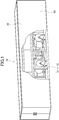
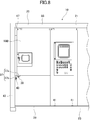
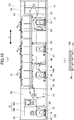
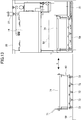
- FIG. 1 It is a partially broken figure which shows the state at the time of transport of the container apparatus by this invention. It is a figure which shows the state at the time of use of the some apparatus installed in the inside of the container apparatus by this invention. It is a bottom view showing a skeleton frame and its peripheral members. It is a top view which shows a skeleton frame and its peripheral member. It is a front view which shows a skeleton frame and its peripheral member. It is a figure which shows the attachment method with respect to the frame
- FIG. 1 the state at the time of transport of the container apparatus 10 by this invention is shown in a partially broken view.
- FIG. 2 shows a front view (a) and a side view (b) of the plurality of devices 11 to 18 installed inside the container device 10 in use.
- the container device 10 includes a rectangular container housing 20 and a plurality of devices 11 to 18 installed in the container housing 20 along the longitudinal direction thereof.
- the devices 11 to 18 each form part of a production line for factory equipment.
- an adhesive tape can be manufactured with these apparatuses 11 to 18 as a whole.
- the container device 10 has a rectangular shape as a whole like a general container, and its appearance is substantially the same as that of a general container.
- the size is in accordance with the normal container standard, and the weight is within the range of the normal container standard including the weight of the devices 11 to 18 installed therein. Accordingly, the container device 10 can be transported in the same manner as a general container.
- the transportation means is not limited to a vehicle such as a trailer but may be a ship, an aircraft, or the like.
- the container housing 20 corresponds to a general container, but has a completely different structure from a general container as described in detail below. Therefore, the container housing 20 of the present invention cannot be substituted with a general container.
- the container housing 20 is provided with a storage space 38 in the same manner as a general container. However, not the normal load but the devices 11 to 18 are accommodated in the accommodation space 38.
- the housing space 38 mainly includes a skeleton frame 21, a plate-like member 28 fixed to the skeleton frame 21, and a plurality of iron plates 50 detachably attached to the skeleton frame 21 so as to cover the outer surface. (Shown in detail in FIG. 6).
- the shape of an iron plate is simplified and shown.
- the devices 11 to 18 are at least partially fixed to at least one of the skeleton frame 21 and the plate-like member 28. Therefore, it cannot be moved freely except for a part of the configuration as in the case of normal factory equipment.
- these devices 11 to 18 are covered with an iron plate 50.
- all of these iron plates 50 are removed and exposed.
- the exposed devices 11 to 18 are used in the same manner as general factory equipment while being fixed to the skeleton frame 21 and the plate-like member 28.
- the function of the container device 10 is determined according to the function of the devices 11 to 18. Since these apparatuses can be freely changed, the container apparatus 10 can function as various factory facilities.
- the devices 11 to 18 shown in FIGS. 1 and 2 function as a coating machine for manufacturing a double-sided tape as a whole.
- the adhesive monomer and additives are dissolved in a solvent, the polymerization process is performed, the adhesive coating liquid obtained in the dissolution process is applied to a film, and then dried.
- the coating process includes drying the solvent with a machine and winding it into a roll, and the finishing process of cutting, finishing, and inspecting the roll-shaped tape base material obtained.
- the container apparatus 10 of the present invention is used, the container apparatus 10 is transported to the site, and if necessary utilities such as water, steam, electricity, etc. are prepared, the coating work is started immediately. be able to.
- the coating process by the container apparatus 10 is performed by a roll-to-roll method, and the apparatus configuration is, for example, for applying a predetermined coating agent to the feeding units 11 and 12 for feeding the substrate and the like, and the drawn substrate and the like.
- Coating unit 13 a drying unit 14 for drying a substrate coated with a predetermined coating agent, a bonding unit 15 for bonding substrates and the like, and winding units 16 and 17 for winding the substrate and the like
- a control unit 18 for controlling these operations is included.
- a steam flow valve 27 is provided above the drying unit 14 so as to take in steam into the drying unit 14 while protruding from the ceiling of the container housing 20. It can be rotated in a direction toward the inside of the container 20, so that it does not protrude from the container device 10 during transportation.
- skeleton frame 21 are demonstrated.
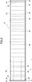
- 3 is a bottom view showing the skeleton frame 21 and its peripheral members
- FIG. 4 is a plan view thereof
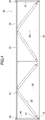
- FIG. 5 is a front view thereof.
- the skeleton frame 21 and the like are all formed of a member having considerable rigidity such as metal or carbon.
- the container device 10 includes the relatively heavy devices 11 to 18, and it is highly possible that the center of gravity of the container device 10 is significantly biased by these heavy devices 11 to 18. In order to withstand the weights and deviations of 18 to 18, a beam having a strength higher than that of a normal iron plate is provided to compensate for the lack of strength.
- the skeleton frame 21 includes at least a rectangular bottom frame 22 that defines the exterior of the bottom side of the container housing 20 shown in FIG.
- the bottom frame 22 extends in parallel along the width direction of the container housing so as to connect two longitudinal beams 23 extending in parallel along the longitudinal direction of the container housing and the ends of the two longitudinal beams 23. It is defined by two horizontal beams 24.
- the longitudinal beam 23 and the horizontal beam 24 may be formed from H steel whose cross-sectional size is 150 mm ⁇ 150 mm, for example.
- a metal plate-like member 28 is fixed to the bottom frame 22 so as to cover substantially the whole.
- the plate-like member 28 can form the inner bottom of the container housing 20, that is, the floor surface.
- the plate-like member 28 may be formed of a flat stainless steel material having a thickness of about 6 mm.
- the connector device 10 adopts the roll-to-roll method. Under this method, the distance between the roll core 74 and the floor surface 28 in each of the devices 11 to 18 (the distance shown in FIG. 2). “A”) is very important. This distance “a” greatly depends on the planar accuracy of the floor surface. In this configuration, by providing the hard plate-like member 28 fixed to the rigid bottom frame 22, sufficient planar accuracy can be easily obtained even in such a roll-to-roll system. In order to improve the planar accuracy, the plate-like member 28 is preferably formed from a single plate.
- a bottom frame reinforcing material 26 may be provided.
- the bottom frame reinforcing member 26 is provided along the width direction of the container housing 20 so as to connect the two longitudinal beams 23 defining the bottom frame 22 to each other.
- the bottom frame reinforcing member 26 can be formed by, for example, a hollow metal square pipe having a rectangular or square cross section.
- a rectangular upper frame 32 that defines the outer exterior of the container housing may be provided as a part of the skeleton frame 21.
- the upper frame 32 extends in parallel along the width direction of the container housing so as to connect the two longitudinal beams 33 extending in parallel along the longitudinal direction of the container housing and the ends of the two longitudinal beams 32. It is defined by two horizontal beams 34.
- the vertical column 43 includes a contact point 25 between the longitudinal beam 23 and the horizontal beam 24 that define the bottom frame 22 shown in FIG. 3, and a longitudinal beam 33 and a horizontal beam 34 that define the top frame 32 shown in FIG. It extends in parallel along the vertical direction so as to connect to the contact point 35.
- These vertical struts 43 can also be formed by, for example, 150 mm ⁇ 150 mm square pipes.
- the upper beam 36 as shown in FIG. 4 and the side reinforcing pillars 44 as shown in FIG. It is also possible to reinforce the skeleton frame 21 by providing oblique reinforcing members 45 and 45 ′.
- the upper beam 36 shown in FIG. 4 is provided along the width direction of the container housing so as to connect the longitudinal beams 33 defining the rectangular upper frame 32.
- the upper beam 36 may be formed of, for example, a 200 mm ⁇ 50 mm square pipe.
- the side reinforcement pillars 44 shown in FIG. 5 are arranged in the vertical direction of the container housing so as to connect the longitudinal beam 23 defining the rectangular bottom frame 22 and the longitudinal beam 34 defining the rectangular upper frame 32. It is provided along.
- These side reinforcing columns 44 may be, for example, a 200 mm ⁇ 50 mm square pipe or a 150 mm ⁇ 150 mm square pipe.
- the oblique reinforcing members 45 and 45 'shown in FIGS. 4 and 5 are connected to the intersections of the longitudinal beams 23 and 33, the horizontal beams 24 and 34, the vertical columns 43, the upper beams 36, and the side reinforcing columns 44 of the container housing. You may provide so that it may connect in the direction which cross
- These members 36, 44, and 45 that reinforce the skeleton frame 21 are used only when the container housing 20 is transported, and are removed together with the iron plate 50 (shown well in FIG. 6) when the devices 11 to 18 are used. . By making it removable, the access to the devices 11 to 18 inside the container housing 20 can be facilitated, and the usability of the devices 11 to 18 arranged inside the container housing 20 can be improved.
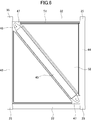
- FIG. 6 shows a method of attaching the steel plate 50 shown in FIG. 1 and the oblique reinforcing members 45 and 45 ′ shown in FIGS. 4 and 5 to the skeleton frame 21.
- 6 corresponds particularly to the side view of the front end in the longitudinal direction of the container device, and is a view showing a method of attaching the oblique reinforcing material 45, but the same applies to the attaching method in other portions. You can think about it.
- a mounting plate 47 is provided at the contacts 25, 35 for connecting the oblique reinforcing material 45.
- the oblique reinforcing member 45 is fixed to these mounting plates 47 with bolts 48 and is detachable from the container housing 20.
- the iron plate 50 is also triangular.
- a sealing material (not shown) is sandwiched between the iron plate 50 and the diagonal reinforcing material 45, the upper frame 32, etc. along the triangular window 51 formed by the diagonal reinforcing material 45 or the like. It is. As a result, intrusion of rain or the like into the accommodation space 38 can be prevented.
- FIGS. 7 to 9 a method of fixing the devices 11 to 18 to the skeleton frame 21 and the plate-like member 28 will be described.
- a method of fixing the control unit 18 and the drying unit 14 will be described, but it may be considered that other portions are also fixed by the same method.
- the target to fix these portions may be the skeleton frame 21 or the plate-like member 28, and any member constituting the skeleton frame 21, that is, the frame constituent members 51 to 53 forming the bottom frame 22, the upper part Any of the frame constituting members 81 to 83 constituting the frame 32 or the vertical column 43 may be used.
- 7 is a front view of the container device 10 near the front end in the longitudinal direction
- FIG. 8 is a cross-sectional view of the container device 10 near the front end of the longitudinal direction
- FIG. 9 is a cross-sectional view of the container device 10 near the middle in the longitudinal direction. is there.
- the main control panel 18 ⁇ / b> A is fixed to the longitudinal beam 23 and the bottom frame reinforcing member 26 which are part of the skeleton frame 21 among the control units 18 installed in the container housing 20.
- the plate-like member 28 is fixed by bolts 41 or welding.
- the auxiliary control panel 18B is fixed to the other side surface by the mounting bracket 37 while one side surface is supported by the main control panel 18A.
- the mounting bracket 37 has a substantially L shape in side view, the rod-shaped member 37a is fixed to the bottom of the auxiliary control panel 18B by bolts 39, welding, or the like, and the rod-shaped member 37b is attached to the vertical column 43 which is a part of the skeleton frame. It is fixed by bolt 40 or welding.
- control unit 18 is firmly fixed to the vertical column 43 which is one of the skeleton frames 21 of the container housing and the plate-like member 28 fixed to the skeleton frame 21. Therefore, the control unit 18 hardly causes misalignment or the like in the container housing 20 during transportation of the container device 10.
- the drying unit 14 installed in the container housing 20 is fixed to the plate-like member 28 by bolts 42 or welding via a dryer column 46.
- the drying unit 14 is fixed by fixing a dryer column 46 to a side reinforcing column 44 that is a part of the skeleton frame 21. Since the drying unit 14 has a predetermined length along the longitudinal direction of the container housing 20, a plurality of dryer columns 46 are also provided along the longitudinal direction of the container housing 20, and the skeleton frame 21 is appropriately selected. It is preferable to fix to the vertical column 43 and the plate-like member 28 which are a part of.
- the recess 55 reduces the strength of the container device 10.
- a reinforcing member 29 such as a square pipe may be arranged over the upper portion of the plate-like member 28 in the length portion “a” (see FIG. 3) of the container device 10. Good.
- These reinforcing members 29 need to be provided in a form avoiding collision with the main control panel 18A and the like.
- FIG. 10A is a diagram showing the first coating process by the same method as FIG. 1, and FIG. 10B is a diagram showing an intermediate product formed through the first coating process.
- FIG. 11 is a figure which shows the 2nd coating process
- (b) is a figure which shows the double-sided tape as a final product formed through the 2nd coating process.
- the first coating process will be described with reference to FIG. As shown to (a) of FIG. 10, first, the roll of the separator film as the base
- the adhesive layer 101 is applied to the fed separator film 53 by the coating unit 13.
- the contents to be included in the adhesive layer 101 and the amounts thereof need to be finely adjusted by an operator, so that the coating unit 13 is preferably provided, for example, at one end 61 in the longitudinal direction of the container device 10. . By providing at such a position, a working space for the worker can be secured.
- the separator film 53 coated with the adhesive layer 101 is sent to the drying unit 14 and the solvent is evaporated by a dryer.
- the drying unit 14 Since the evaporation of the solvent requires a relatively long time compared to other operations, the drying unit 14 has a predetermined length along the longitudinal direction “b” of the container device 10. Thereafter, the nonwoven fabric 102 fed from the feeding portion 12 provided at the other end 62 in the longitudinal direction “b” and the separator film 53 that has passed through the drying portion 14 are bonded together at the bonding portion 15. Finally, the intermediate product 100 that is a completed product in the first coating process is wound up by the winding unit 16 while the separator film 53 that has been bonded is wound up by the winding unit 17.
- the intermediate product 100 includes a separator film 53, an adhesive layer 101, and a nonwoven fabric 102 in this order as shown in FIG.
- the second coating process will be described with reference to FIG.
- the adhesive layer 103 is applied to the fed intermediate product 100 by the coating unit 13.
- the intermediate product 100 coated with the adhesive layer 103 is sent to the drying unit 14, and the solvent is evaporated by a dryer.
- the separator film 104 fed from the feeding unit 12 provided at the other end 62 of the container device 10 and the intermediate product 100 that has passed through the drying unit 14 are bonded together by the bonding unit 15.
- the double-sided tape 105 as the final product is wound up by the winding unit 17 while the separator film 104 is peeled off and wound up by the winding unit 16.
- the final product includes a separator film 53, an adhesive layer 101, a nonwoven fabric 102, and an adhesive layer 103 in this order.
- FIG. 12 is a plan view showing the working stage 58 together with the container housing 20.
- the work stage 58 may be formed by arranging a plurality of iron plates in parallel. If the work stage 58 is used, for example, the carriage 60 inserted into and removed from the container housing 20 can be smoothly moved. The cart 60 is moved from one side of the container housing 20 in the direction (arrow “c” in the figure) intersecting the longitudinal direction (arrow “b” in the figure) of the container housing 20, for example. Further, it is arranged at a position lower than the processing in the coating unit 13 and the drying unit 18 and is drawn out therefrom.
- FIG. 13 shows a front view of the carriage 60 placed on the work stage 58.
- the carriage 60 includes a gripping portion 71, a roll core 74, and two types of wheels 72 and 73 provided on the bottom side of the carriage 60.
- the roll core 74 When the cart 60 is accommodated in the container housing 20, the roll core 74 is aligned with the driving unit 31 provided in the feeding units 11 and 13 and the winding units 16 and 17 at one end thereof. When feeding or winding, the roll core 74 is rotated by the driving force from the driving unit 31.
- one wheel 72 is a hard and small metal wheel having a relatively small diameter, and is mainly used inside the container apparatus 10.
- the other wheel 73 is a wheel having a rough surface made of nylon having a relatively large diameter, and is mainly used outside the container device 10.
- the wheel 73 is disposed at a position lower than the wheel 72.
- FIG. 14 shows an arrangement state of these two types of wheels 72 and 73 as seen from the bottom side of the carriage 60.
- the wheels 72 are arranged in two rows at the center along the direction “c” intersecting the longitudinal direction of the container housing 20, and the wheels 73 are arranged along the same direction so as to sandwich the outside of the wheels 72. A total of two rows are arranged.
- rails 59 for supporting the wheels 72 are particularly provided in the container device 10, particularly in the plate-like member 28.
- the cart 60 is pulled out from the container housing 20, the cart 60 is supported only by the wheels 73, and the wheels 72 are in a suspended state. Therefore, in this case, dust does not adhere to the wheel 72 or wear.
- the cart 60 is pushed into the container housing 20, the cart 60 is supported by the rail 59 that exists only in a portion corresponding to the arrangement of the wheels 72, and is supported only by the wheels 72.
- the rail 59 does not exist in the portion corresponding to the arrangement of the wheels 73, the wheels 73 are in a floating state inside the container housing 20. The wear state does not prevent the roll core 74 from being aligned with the drive unit 31 of the container housing 20.
- Any equipment that can be accommodated in the size of a container can be applied to various equipment.
Landscapes
- Engineering & Computer Science (AREA)
- Architecture (AREA)
- Civil Engineering (AREA)
- Structural Engineering (AREA)
- Rigid Containers With Two Or More Constituent Elements (AREA)
Abstract
La présente invention concerne un appareil formant contenant grâce auquel une usine peut être transportée telle quelle. L'appareil formant contenant est pourvu : d'un logement de contenant de forme rectangulaire ; et d'une pluralité d'équipements qui est installée à l'intérieur du logement de contenant dans la direction longitudinale du logement de contenant, chaque équipement faisant partie d'une chaîne de production de l'usine. Au moins une partie de chaque équipement parmi la pluralité d'équipements est fixée à un cadre d'ossature du logement de contenant et/ou à un élément en forme de plaque, qui est fixé au cadre d'ossature et définit le fond intérieur du logement de contenant. Le cadre d'ossature du logement de contenant comprend au moins un cadre de fond rectangulaire qui forme l'extérieur du logement de contenant. Le cadre de fond est défini par deux poutres longitudinales, qui s'étendent en parallèle dans le sens longitudinal du logement de contenant, et deux poutres horizontales, qui s'étendent en parallèle dans le sens de la largeur du logement de contenant, de manière telle à raccorder les deux poutres longitudinales.
Applications Claiming Priority (2)
| Application Number | Priority Date | Filing Date | Title |
|---|---|---|---|
| JP2012-004835 | 2012-01-13 | ||
| JP2012004835A JP2013144555A (ja) | 2012-01-13 | 2012-01-13 | コンテナ装置 |
Publications (1)
| Publication Number | Publication Date |
|---|---|
| WO2013105337A1 true WO2013105337A1 (fr) | 2013-07-18 |
Family
ID=48781301
Family Applications (1)
| Application Number | Title | Priority Date | Filing Date |
|---|---|---|---|
| PCT/JP2012/079628 Ceased WO2013105337A1 (fr) | 2012-01-13 | 2012-11-15 | Appareil formant contenant |
Country Status (2)
| Country | Link |
|---|---|
| JP (1) | JP2013144555A (fr) |
| WO (1) | WO2013105337A1 (fr) |
Cited By (2)
| Publication number | Priority date | Publication date | Assignee | Title |
|---|---|---|---|---|
| WO2017002203A1 (fr) * | 2015-06-30 | 2017-01-05 | 株式会社エコプラナ | Installation de production de carburant à base de carbone et installation de production simple de carburant à base de carbone de type cuve |
| CN110203571A (zh) * | 2019-05-29 | 2019-09-06 | 中国科学院工程热物理研究所 | 一种适用于小型航空发动机的运转箱结构 |
Families Citing this family (3)
| Publication number | Priority date | Publication date | Assignee | Title |
|---|---|---|---|---|
| CA2934062A1 (fr) * | 2013-12-16 | 2015-06-25 | Mis.Carbonart Pty Ltd | Conteneur de construction legere |
| KR102570847B1 (ko) * | 2021-07-21 | 2023-08-29 | (주)한중특장 | 워킹카용 적재함 구조 |
| KR102744556B1 (ko) * | 2022-02-24 | 2024-12-18 | 비케이전자 주식회사 | 컨테이너형 마스크 제조장치 |
Citations (8)
| Publication number | Priority date | Publication date | Assignee | Title |
|---|---|---|---|---|
| JPS58194123U (ja) * | 1982-06-21 | 1983-12-23 | 梅村実業株式会社 | 組立式の輸送用コンテナ |
| JPS624092A (ja) * | 1985-02-14 | 1987-01-10 | ヴアイトマン ウント ピテイ ソシエテ アノニム | 大型の処分可能な一貫輸送用荷送り箱 |
| JPH02160590A (ja) * | 1988-05-26 | 1990-06-20 | Sakata Corp | 光沢印刷物の製造方法及びそれに適した装置 |
| JPH10278929A (ja) * | 1997-03-31 | 1998-10-20 | Honda Motor Co Ltd | リターナブルケース |
| JPH1165075A (ja) * | 1997-08-18 | 1999-03-05 | Fuji Photo Film Co Ltd | 画像形成用溶媒塗布方法 |
| JP2000254673A (ja) * | 1999-03-05 | 2000-09-19 | Shigen Seibutsu Kenkyusho:Kk | コンテナ型汚水処理装置 |
| JP2007261611A (ja) * | 2006-03-28 | 2007-10-11 | Japan Atomic Energy Agency | コンテナ |
| JP2007278136A (ja) * | 2006-04-04 | 2007-10-25 | Mizuho:Kk | コンテナ脱着式発電装置 |
-
2012
- 2012-01-13 JP JP2012004835A patent/JP2013144555A/ja active Pending
- 2012-11-15 WO PCT/JP2012/079628 patent/WO2013105337A1/fr not_active Ceased
Patent Citations (8)
| Publication number | Priority date | Publication date | Assignee | Title |
|---|---|---|---|---|
| JPS58194123U (ja) * | 1982-06-21 | 1983-12-23 | 梅村実業株式会社 | 組立式の輸送用コンテナ |
| JPS624092A (ja) * | 1985-02-14 | 1987-01-10 | ヴアイトマン ウント ピテイ ソシエテ アノニム | 大型の処分可能な一貫輸送用荷送り箱 |
| JPH02160590A (ja) * | 1988-05-26 | 1990-06-20 | Sakata Corp | 光沢印刷物の製造方法及びそれに適した装置 |
| JPH10278929A (ja) * | 1997-03-31 | 1998-10-20 | Honda Motor Co Ltd | リターナブルケース |
| JPH1165075A (ja) * | 1997-08-18 | 1999-03-05 | Fuji Photo Film Co Ltd | 画像形成用溶媒塗布方法 |
| JP2000254673A (ja) * | 1999-03-05 | 2000-09-19 | Shigen Seibutsu Kenkyusho:Kk | コンテナ型汚水処理装置 |
| JP2007261611A (ja) * | 2006-03-28 | 2007-10-11 | Japan Atomic Energy Agency | コンテナ |
| JP2007278136A (ja) * | 2006-04-04 | 2007-10-25 | Mizuho:Kk | コンテナ脱着式発電装置 |
Cited By (3)
| Publication number | Priority date | Publication date | Assignee | Title |
|---|---|---|---|---|
| WO2017002203A1 (fr) * | 2015-06-30 | 2017-01-05 | 株式会社エコプラナ | Installation de production de carburant à base de carbone et installation de production simple de carburant à base de carbone de type cuve |
| JPWO2017002203A1 (ja) * | 2015-06-30 | 2018-04-12 | 株式会社エコプラナ | 炭素系燃料製造プラント及びコンテナ型炭素系燃料製造簡易プラント |
| CN110203571A (zh) * | 2019-05-29 | 2019-09-06 | 中国科学院工程热物理研究所 | 一种适用于小型航空发动机的运转箱结构 |
Also Published As
| Publication number | Publication date |
|---|---|
| JP2013144555A (ja) | 2013-07-25 |
Similar Documents
| Publication | Publication Date | Title |
|---|---|---|
| WO2013105337A1 (fr) | Appareil formant contenant | |
| US20090057066A1 (en) | Stacker crane and weight reduction method for mast of the stacker crane | |
| CN104554623B (zh) | 船艉部总段运输工装 | |
| CN205276725U (zh) | 一种超长彩钢屋面板施工工艺中的平移小车 | |
| JPH07205881A (ja) | 準備部材からなる床なしの非自己運搬型の船室 | |
| TWI632104B (zh) | 用於廠房內固定天車軌道之裝置及使用該裝置之載物系統 | |
| KR102018247B1 (ko) | 초중량급 중량물 운반장치 | |
| CN109083274A (zh) | 角柱可拆的装配式钢结构建筑组合模块 | |
| CN203213622U (zh) | 施工物料装卸设备 | |
| CN204024084U (zh) | 便卸式三角管桁架正拼胎架 | |
| CN202072183U (zh) | 一种集装箱 | |
| CN205575088U (zh) | 客车侧窗玻璃转运货架 | |
| JP2019206423A (ja) | 揚重雇、及び、その楊重雇を用いた重量物の楊重運搬方法 | |
| CN206407419U (zh) | 一种集装箱及活动顶板 | |
| KR101263580B1 (ko) | 크레인의 횡행 레일을 밀착시키는 장치 | |
| CN103216092A (zh) | 施工物料装卸方法及其设备 | |
| CN113928498A (zh) | 一种双燃料大型集装箱船特殊分段的搁置运输方法 | |
| JP5365958B2 (ja) | プラント施設建設におけるモジュール工法およびモジュール工法用定盤 | |
| CN203638467U (zh) | 干货集装箱底架部件及干货集装箱 | |
| CN223494392U (zh) | 一种新式卷板架结构 | |
| CN105730836A (zh) | 一种废料周转箱的框架 | |
| CN202704813U (zh) | 一种运送铁路货车转向架侧架的专用料架 | |
| KR20150001734U (ko) | 대형 크레인의 케이블릴 보조장치 | |
| JP5198599B2 (ja) | 大扉システムの生産方法 | |
| KR20140145249A (ko) | 선박의 선행화 방법 |
Legal Events
| Date | Code | Title | Description |
|---|---|---|---|
| 121 | Ep: the epo has been informed by wipo that ep was designated in this application |
Ref document number: 12865176 Country of ref document: EP Kind code of ref document: A1 |
|
| NENP | Non-entry into the national phase |
Ref country code: DE |
|
| 122 | Ep: pct application non-entry in european phase |
Ref document number: 12865176 Country of ref document: EP Kind code of ref document: A1 |