WO2017002203A1 - Installation de production de carburant à base de carbone et installation de production simple de carburant à base de carbone de type cuve - Google Patents
Installation de production de carburant à base de carbone et installation de production simple de carburant à base de carbone de type cuve Download PDFInfo
- Publication number
- WO2017002203A1 WO2017002203A1 PCT/JP2015/068864 JP2015068864W WO2017002203A1 WO 2017002203 A1 WO2017002203 A1 WO 2017002203A1 JP 2015068864 W JP2015068864 W JP 2015068864W WO 2017002203 A1 WO2017002203 A1 WO 2017002203A1
- Authority
- WO
- WIPO (PCT)
- Prior art keywords
- water
- processing unit
- carbon
- molecules
- oil
- Prior art date
- Legal status (The legal status is an assumption and is not a legal conclusion. Google has not performed a legal analysis and makes no representation as to the accuracy of the status listed.)
- Ceased
Links
Images


Classifications
-
- C—CHEMISTRY; METALLURGY
- C10—PETROLEUM, GAS OR COKE INDUSTRIES; TECHNICAL GASES CONTAINING CARBON MONOXIDE; FUELS; LUBRICANTS; PEAT
- C10L—FUELS NOT OTHERWISE PROVIDED FOR; NATURAL GAS; SYNTHETIC NATURAL GAS OBTAINED BY PROCESSES NOT COVERED BY SUBCLASSES C10G OR C10K; LIQUIFIED PETROLEUM GAS; USE OF ADDITIVES TO FUELS OR FIRES; FIRE-LIGHTERS
- C10L1/00—Liquid carbonaceous fuels
- C10L1/02—Liquid carbonaceous fuels essentially based on components consisting of carbon, hydrogen, and oxygen only
-
- C—CHEMISTRY; METALLURGY
- C10—PETROLEUM, GAS OR COKE INDUSTRIES; TECHNICAL GASES CONTAINING CARBON MONOXIDE; FUELS; LUBRICANTS; PEAT
- C10L—FUELS NOT OTHERWISE PROVIDED FOR; NATURAL GAS; SYNTHETIC NATURAL GAS OBTAINED BY PROCESSES NOT COVERED BY SUBCLASSES C10G OR C10K; LIQUIFIED PETROLEUM GAS; USE OF ADDITIVES TO FUELS OR FIRES; FIRE-LIGHTERS
- C10L1/00—Liquid carbonaceous fuels
- C10L1/32—Liquid carbonaceous fuels consisting of coal-oil suspensions or aqueous emulsions or oil emulsions
Definitions
- the present invention relates to a carbon-based fuel manufacturing plant that manufactures high-quality carbon-based fuels using petroleum and water as raw materials, and a container-type carbon-based fuel manufacturing simple plant.
- the Fischer-Tropsch process which uses a catalytic reaction to synthesize liquid hydrocarbons from carbon monoxide and hydrogen to purify carbon-based fuels, uses carbon monoxide and hydrogen as starting materials, and hydrocarbons such as methane as gases.
- the steam reforming method utilizes a thermal reaction with high-temperature steam.
- Patent Document 1 discloses a method for producing a hydrocarbon containing at least one of a liquefied petroleum gas component and a gasoline component by utilizing a reaction between carbon monoxide and hydrogen.
- carbon monoxide and hydrogen are mixed with a fluid having a temperature of 230 ° C. or higher and a pressure of 0.1 MPa or higher, the mixture is brought into contact with a catalyst, and carbon monoxide and hydrogen in the mixture are reacted.
- a fluid having a temperature of 230 ° C. or higher and a pressure of 0.1 MPa or higher
- Patent Document 2 As a method for producing a reaction product by reacting an organic compound and water, Patent Document 2 shown below can be mentioned.
- a method for producing a reaction product ie, synthetic petroleum
- a fluid mixture of an organic compound such as glycidyl ether
- subcritical water water that is 100 ° C. or higher and lower than 374 ° C. and in a liquid state
- a reaction product is produced by setting the reaction field temperature of the mixed fluid to about 150 ° C. to 374 ° C. and the reaction field pressure to about 0.1 to 30 MPa.
- the Fischer-Tropsch process requires generation of high-temperature steam.
- a high-temperature fluid of at least 230 ° C. or higher.
- the temperature of the reaction field is about 150 ° C. to 374 ° C., and at least the reaction field needs to be kept at a high temperature.
- all of the above methods require heat energy to raise the temperature, so that it is a problem to consume oil to produce a substitute for petroleum.
- it in order to realize such high-temperature heat treatment, it will inevitably require large facilities, space and time, and it will not contribute to the reduction of carbon dioxide. The contradiction is recognized.
- the present invention has been made in view of the above circumstances, and a carbon-based fuel production plant for producing high-quality and high-combustion carbon-based fuel by a simple method using petroleum and water as raw materials, and a simple production of container-type carbon-based fuel.
- the purpose is to provide a plant.
- a carbon-based fuel production plant comprises an oil refinement processing unit for separating oil molecules, which is provided with a fuel filler opening and has a cavitation generating ring built in a pipe.
- a water pulverization processing unit for separating water molecules, a cavitation generation ring built in the piping, the oil refinement processing unit, and the water A fuel generation processing unit that combines oil molecules and water molecules separated by the miniaturization processing unit, a water separation processing unit that separates the water of the carbon-based product generated in the fuel generation processing unit, and the water A discharge port for discharging the final carbon-based fuel after the water is separated by the separation processing unit, and a reflux process for returning the water separated by the water separation processing unit to the water refinement processing unit. Characterized in that a part.
- the container-type carbon-based fuel production simplified plant includes a water refinement processing unit for separating petroleum molecules, a cavitation generating ring built in a pipe, and a water cavitation generating ring built in the pipe.
- the water refinement processing unit for separating the molecules of the oil, the cavitation generation ring is built in the pipe, the oil and water molecules separated by the oil refinement treatment unit and the water refinement treatment unit.
- the fuel generation processing unit to be combined, the water separation processing unit for separating the water of the carbon-based product generated by the fuel generation processing unit, and the water separated by the water separation processing unit to the water refinement processing unit A recirculation treatment unit that recirculates the oil refinement treatment unit, the water refinement treatment unit, the fuel generation treatment unit, the water separation treatment unit, and the reflux treatment unit in a container housing.
- a carbon-based fuel can be produced by a new and simple method using a cavitation phenomenon using petroleum and water as raw materials.
- a step of removing moisture from the carbon-based product generated in the fuel generation processing unit is added, a high-quality final carbon-based fuel capable of long-term storage and stable combustion can be obtained.
- the water separated from the carbon-based product is reused as a raw material, the water is not drained from the plant, the raw material can be reduced to zero emission, and there is no need to separately prepare a waste water treatment facility. Therefore, installation costs can be reduced.
- the plant components are built in the container housing, the complete plant can be easily transported in a completed form, similar to general marine transportation and land transportation. Installation on site is also very easy.
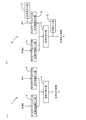
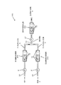
- (A) And (b) is process drawing which shows an example of the basic manufacturing method of the carbonaceous fuel which concerns on this invention. It is the schematic of an example of the manufacturing apparatus of the carbonaceous fuel which concerns on this invention.
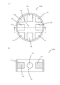
- (A) is a schematic plan view of an example of a cavitation generating ring, and (b) is a schematic longitudinal sectional view taken along line XX.
- (A) is a schematic plan view of another example of the cavitation generating ring, and (b) is a schematic longitudinal sectional view taken along line YY.
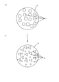
- (A) is the schematic which shows typically the bubble before a cavitation process
- (b) is the schematic which shows typically the nanobubble after a cavitation process.
- Basic production method of carbon-based fuel according to the present invention that is, petroleum and water as raw materials are refined by cavitation, and the refined petroleum molecules and water molecules are combined by cavitation to generate new carbon-based fuel
- the water content in the produced carbon-based product is about 1 to 50% of water as a raw material.
- this product can be burned as fuel as it is, the present embodiment adds a step of removing moisture from the product to this basic manufacturing method, so that moisture can be stored even for long-term storage. The purpose is to obtain a high-quality carbon-based fuel that does not separate.
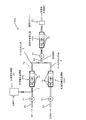
- FIG. 1 is a basic block diagram of such a carbonized fuel production plant 100B.
- the carbon-based fuel production plant 100B is provided with the oil supply port 23, the oil refinement processing unit 200 for separating the oil molecules, the cavitation generating ring 10 built in the pipe 20, and the water supply port 32.
- the fuel generation processing unit 400 that generates the carbon-based product 9 by combining the oil molecules and the water molecules separated by the chemical conversion processing unit 300, and the water content of the carbon-based product 9 generated by the fuel generation processing unit 400
- Oil-water separation includes, for example, a method using a difference in specific gravity of oil and water, a method using a liquid-liquid separation filter, and the like, and any of them can be used as a water separation processing unit.
- the reflux processing unit 600 mixes the water 4 supplied from the water supply port 32 and the water 4A separated by the water separation processing unit 500, and defines the mixture with respect to the oil 2 supplied from the oil supply port 23. It has a function of supplying the water refinement processing unit 300 by controlling so as to keep the volume% of the water.
- the reflux processing unit 600 may include a mixing tank and a float valve that automatically opens and closes the water supply port 32 according to the level of the mixing tank (not shown).
- a high-quality final carbon-based fuel 9A that can be stored for a long time and stably burned can be obtained.
- the moisture 4A separated from the carbon-based product 9 is reused as a raw material, the moisture 4A is not drained from the carbon-based fuel production plant 100B, and there is no need to separately prepare a wastewater treatment facility or the like. Therefore, the equipment cost can be reduced.
- FIG. 2 is a basic block diagram of such a container-type carbon-based fuel production simplified plant. Elements common to FIG. 5 have the same reference numerals.
- a container-type carbon-based fuel production simplified plant 100C has a cavitation generation ring 10 built in a pipe 20 and an oil refinement processing unit 200 for separating oil molecules, and a cavitation generation ring 10 built in a pipe 30.
- the oil refining treatment unit 200, the water refining treatment unit The unit 200, the fuel generation processing unit 400, the water separation processing unit 500, and the reflux processing unit 600 are installed in the container housing 17, and the oil supply port 23 of the oil refinement processing unit 200 and the water supply port 32 of the water refinement processing unit 300 A discharge port 51 is provided outside the container housing 17 for discharging the final carbon-based fuel 9A after the water 4A is separated by the water separation processing unit 500.
- the size of the container housing 17 is not particularly limited, but a general 20-foot container, 40-foot container, or the like may be used.
- Each processing unit and piping constituting the plant may be fixed to the container housing 17 by a method having earthquake resistance in order to prevent failure during transportation.
- the simple container-type carbon-based fuel production plant 100C further includes a data processing communication unit that accumulates history data such as the amount of oil input, the amount of water, and the final carbon-based fuel produced, and notifies a predetermined center device through a network or the like. Remote operation from the center device may be enabled. In such a case, the center device can always operate the container-type carbon-based fuel production simple plant 100C, and can automatically operate the container-type carbon-based fuel production simple plant 100C by automatically requesting maintenance from the contractor. become.
- the first basic production method 1 is a method for producing a carbon-based product 9 from petroleum 2 and water 4 as shown in FIG. And a water refining step B that divides the molecules of water 4 and a fuel generation step C that combines the molecules separated in these steps into a carbon-based product 9.
- the basic manufacturing method 1 includes an oil refinement processing unit 200 including a cavitation generation ring (ring) 10, a water refinement processing unit 300 including the ring 10, and a ring 10. This is implemented by the carbon-based fuel production plant 100 including the fuel generation processing unit 400.
- the first cavitation generation ring (first ring) 10 is installed in the middle of the pipe 20 through which the oil 2 circulates, and the oil 2 is passed through the first ring 10 at a high pressure.
- the oil refinement processing unit 200 including a plurality of first rings 10 is used to divide the oil 2 molecules.
- oil 2 is passed through the first ring 10 at high pressure by a pump 21 provided in the pipe 20.
- the molecules of the oil 2 are divided, and the oil 2 containing the divided oil molecules (nanoized oil) 3 is obtained.
- the molecules of petroleum 2 are partly bonded (one or a plurality of positions) between carbon atoms in the molecule, and are highly reactive low molecules. It is thought that it becomes. That is, it can be inferred that the carbon number contained in the divided oil molecule is smaller than the carbon number contained in the oil 2 molecule before the division.
- various petroleum fuels mainly composed of hydrocarbons can be used.
- light oil having about 10 to 20 carbon atoms c heavy oil, a heavy oil, gasoline having about 4 to 10 carbon atoms, or the like may be used.
- things such as a paraffin type, an olefin type, a naphthene type, an aromatic type, can be used.
- a paraffin-based one is desirable in terms of providing a high yield of the product 9.
- the second cavitation generation ring (second ring) 10 is installed in the middle of the pipe 30 through which the water 4 flows, and the water 4 is passed through the second ring 10 at a high pressure.
- cavitation is generated in the second ring 10 to sever the molecules of the water 4.
- the water 4 molecules are divided using a water refinement processing unit 300 including a plurality of second rings 10. Further, the water 4 is allowed to pass through the second ring 10 at a high pressure by a pump 31 provided in the pipe 30.
- the water 4 is treated in the water refining step B, whereby the water 4 molecules are divided, and the water 4 contains the water molecules that have been divided and activated (nanoized water) 5. . Due to the fragmentation of the water 4 molecules, hydrogen atoms and oxygen atoms are cut out from the water 4 molecules, and the separated water molecules (that is, molecules composed of only hydrogen atoms or oxygen atoms, some It is considered that a molecule lacking a hydrogen atom or an oxygen atom is generated. Examples of the water 4 include tap water, natural water such as well water, distilled water, ion exchange water, water subjected to reverse osmosis treatment, water subjected to magnetic treatment or electrolysis treatment, and water containing mineral components. Etc., various things can be used.
- a third part of the pipe 40 through which the mixture 8 of the petroleum molecules divided in the oil refinement step A and the water molecules divided in the water refinement step B flows is the third.
- a cavitation generation ring (third ring) 10 is installed, and the mixture 8 is allowed to pass through the third ring 10 at high pressure, thereby causing cavitation in the third ring 10 and separating the separated oil molecules.
- the carbon-based product 9 (product containing hydrocarbon as a main component) is generated by combining with water molecules.
- the content (volume%) of water 4 used in production method 1 may be, for example, 30 to 50 or the like.
- the fuel generation step C uses a fuel generation processing unit 400 including a plurality of third rings 10 to combine the separated petroleum molecules and the separated water molecules to form a carbon-based product. 9 is generated. Further, the mixture 8 is allowed to pass through the third ring 10 at a high pressure by a pump 41 provided in the pipe 40. When the mixture 8 is processed in the fuel generation step C, the separated petroleum molecules and the separated water molecules present in the mixture 8 are combined to produce a new carbon-based product 9.
- single or multiple fragmented petroleum molecules molecules whose carbon number is smaller than the original petroleum 2 molecule
- single or multiple fragmented water molecules hydrogen atoms
- the ring 10 used for the manufacturing method 1 (carbon-based fuel manufacturing plant 100) will be described.
- the ring 10 is used by being installed in a part of the pipes 20, 30, 40 through which liquid (oil 2, water 4, mixture 8) flows.
- the ring 10 has a cylindrical portion 11 in which a flow passage 16 for liquid (petroleum 2, water 4, mixture 8) is formed inside the cylindrical portion 11. It is set as the structure which made the some protrusion parts 12 and 13 protrude from the inner peripheral surface toward the center. Cavitation occurs in the cylindrical portion 11 by allowing the liquid to pass through the cylindrical portion 11 at a high pressure.
- the pressure of the liquid passing through the ring 10 may be about 1 to 10 MP, and the flow rate of the liquid may be 150 m / min or more.
- the pressure and flow rate of the liquid may be appropriately adjusted in order to generate effective cavitation, and may be adjusted according to the temperature, viscosity, etc. of the liquid, for example.
- the ring 10 has a plurality of protrusions 12 (four in the illustrated example) and a plurality of protrusions 13 (four in the illustrated example) that are substantially the same size and shape. It is larger than the part 12. Moreover, the some protrusion parts 12 and 13 of the ring 10 are made into the shape of a mushroom, respectively, and the size of these head parts 12a and 13a is made into the combination of two or more types. In the example of the figure, the shape of the heads 12a and 13a is substantially disk-like, and the ring 10 having two types of heads 12a and 13a is illustrated.
- the size of the heads 12a and 13a may be set so as not to interfere with the protrusions 12 and 13 of each other.
- the sizes of the heads 12a and 13a are not limited to those shown in the drawings, and heads having different sizes such as three types or four types may be used.
- the inner diameter of the cylindrical portion 11 of the ring 10 may be, for example, 10 to 50 mm, and the width dimension (a dimension along the liquid flow direction) of the cylindrical portion 11 may be, for example, 5 to 30 mm.
- the protrusion dimensions of the protrusions 12 and 13 may be dimensions that do not interfere with the protrusions 12 and 13, for example, may be approximately 1/10 to 1/2 of the inner diameter of the cylindrical part 11.
- the ring 10 may be made of an oxide-based ceramic such as aluminum oxide or zirconia, or may be made of a metal such as stainless steel or a synthetic resin.
- the ring 10 is not limited to the one having the projections 12 and 13 having the shape shown in FIGS. 5A and 5B, but the projection 14 having the shape shown in FIGS. 6A and 6B.
- a ring 10A having 15 may be used.
- FIGS. 6A and 6B show a ring 10 ⁇ / b> A including a mountain-shaped protrusion 14 and a cylindrical protrusion 15 in a cross-sectional view.
- the protrusions are not limited to these shapes, and can have various shapes.
- the ring 10 is configured by combining two or more types of heads 12a and 13a, vacuum microbubbles can be generated efficiently, and the oil 2 and water 4 molecules are more efficiently generated. In addition to being able to be divided, these divided molecules can be combined more efficiently.
- the oil refinement processing unit 200, the water refinement processing unit 300, and the fuel generation processing unit 400 may be configured by connecting a plurality of rings 10 that can be connected and separated from each other. These devices 10, 300, and 400 are configured by connecting the plurality of rings 10 such that the insides of the cylinders communicate with each other. It is possible to increase or decrease the amount of cavitation generated by appropriately increasing or decreasing the number of connected rings 10 constituting each processing unit 200, 300, 400. If the number of rings 10 is increased, the amount of cavitation increases, and the above-mentioned shock wave and high heat generation region increases. Therefore, the degree of fragmentation of the oil 2 and water 4 molecules can be increased, and these are separated. The degree of binding between molecules can be increased. On the other hand, if the number of rings 10 connected is reduced, the degree of fragmentation of the oil 2 and water 4 molecules and the degree of bond between the separated molecules can be reduced.
- the degree of fragmentation of the oil 2 and water 4 molecules and the degree of bond between the separated molecules can be adjusted. Therefore, depending on the temperature, viscosity, etc. of petroleum 2, water 4, and mixture 8, the degree of fragmentation of the oil 2 and water 4 molecules and the degree of bond between the separated molecules may vary.
- the amount of cavitation can be adjusted by appropriately increasing or decreasing the number of connected rings 10 in order to obtain the degree of coupling.
- the pumps 21, 31, and 41 may be any pump that can circulate liquid (petroleum 2, water 4, mixture 8) through the pipes 20, 30, and 40 at a high pressure. Can be used.
- a plunger pump, a gear pump, a cascade pump, or the like may be used as the pumps 21, 31, 41.
- the pipes 20, 30, and 40 may have any structure that can withstand the flow of high-pressure liquid (petroleum 2, water 4, and mixture 8).
- pipes 20, 30, and 40 are made of metal such as iron or copper Or what consists of synthetic resins, such as polyvinyl chloride, may be used.
- the diameters of the pipes 20, 30, and 40 may be 1 to 20 mm, for example.
- liquids obtained by diluting the sample with acetone are saturated hydrocarbons (C9H20 to C27H56) and carboxylic acid esters (methyl palmitate, methyl oleate). A strong peak was detected.
- carboxylic acid esters methyl palmitate and methyl oleate
- the formation mechanism of these carboxylic acid esters is that the oxygen derived from the water molecule 4a, which is divided and activated by the fragmentation of the clusters, binds to the petroleum 2 molecules fragmented by cavitation. It is thought that it was generated.
- the manufacturing plant 100 and the cavitation generation ring (ring) 10, it is possible to efficiently refine a petroleum molecule and a water molecule to produce a carbon-based product from petroleum and water.
- the ring 10 is a simple structure including the cylindrical portion 11 and the protrusions 12 and 13, but separates liquid molecules such as oil 2 and water 4 by cavitation generated in the ring 10. Can do.
- the ring 10 having such a simple structure is used to divide the molecules of petroleum 2 and water 4 by cavitation generated in the ring 10.
- the carbon-based product 9 can be produced by combining these divided petroleum molecules and water molecules.
- the carbon-based product 9 is produced by dividing the oil 2 molecule and the water 4 molecule by cavitation in this way, for example, the frequency at which oil 2 and water 4 resonate with these liquids. Compared to the case where the molecules are divided by applying the above-described wave, the molecules can be divided relatively accurately with high accuracy. In addition, since the molecular fragmentation accuracy can be increased in this way, as a result, the quality of the carbon-based product 9 is stabilized and the yield is also improved.
- the manufacturing method 1A includes a gas-liquid mixing step D in which a large number of bubbles 7 are included in the water 4 before being processed in the water refinement step B.
- This carbon-based fuel manufacturing method 1A is implemented by a carbon-based fuel manufacturing plant 100A equipped with a gas-liquid mixing device 22, as shown in FIG.
- the gas 6 is mixed into the pipe 30 through which the water 4 upstream from the first cavitation generating ring 10 (first ring) flows, so that the water 4 contains a large number of bubbles 7. ing.
- FIG. 8A shows the bubbles 7 before being miniaturized to nano size
- FIG. 8B shows the nano bubbles 7a.
- the size of the bubbles 7 is about 200 to 2000 ⁇ m
- the size of the nanobubbles 7a is about 100 to 500 nm. Due to the cavitation generated in the first ring 10, vacuum microbubbles are generated in the water 4, and when the vacuum microbubbles collide with the bubbles 7 generated in the water 4, the bubbles 7 are formed.
- the nanobubbles 7a are instantly destroyed (miniaturized). It is considered that a sudden adiabatic compression reaction occurs at the time of this destruction, and an extreme reaction field of ultrahigh pressure and ultrahigh temperature is formed in the nanobubbles 7a. It is considered that the molecules of the water 4 are efficiently divided by the extreme reaction field acting on the water 4 around the nanobubbles 7a.
- the manufacturing method 1 ⁇ / b> A further includes a stabilization step E that stabilizes the molecular bond of the carbonized product generated in the fuel generation step C.
- this stabilization step E the product is passed through the magnetic mixer 43 to stabilize the molecular bonds of the product.
- negative ions are imparted to the product. This makes it difficult for the products to stick to each other due to the repulsive action between the negative ions.
- the magnetic mixer 43 what is necessary is just to be able to give a negative ion with respect to a product, and what was made into various structures can be used.
- the manufacturing method 1A includes a gas-liquid mixing step D in which a large number of bubbles 7 are included in the water 4 before being processed in the water refinement step B, the vacuum microbubbles generated in the water 4 by cavitation However, it collides with the bubbles 7 and instantaneously breaks the bubbles 7 into nanobubbles 7a, which causes a sudden adiabatic compression phenomenon, so that the water 4 molecules around the nanobubbles 7a are efficiently divided.
- the production method 1A further includes a stabilization step E for stabilizing the molecular bond of the product formed by combining the divided petroleum molecules and the divided water molecules.
- gas-liquid mixing device and the magnetic mixer shown here can be similarly incorporated into the carbonized fuel production plant shown in FIG. 1 and the container-type carbon fuel simple production plant shown in FIG.
Landscapes
- Chemical & Material Sciences (AREA)
- Oil, Petroleum & Natural Gas (AREA)
- Engineering & Computer Science (AREA)
- Chemical Kinetics & Catalysis (AREA)
- General Chemical & Material Sciences (AREA)
- Organic Chemistry (AREA)
- Liquid Carbonaceous Fuels (AREA)
Abstract
La présente invention comprend : une unité de traitement du raffinage de pétrole 200 destinée à diviser des molécules de pétrole, et comprenant des anneaux de production de cavitation 10, chaque anneau étant construit dans une tuyauterie de cette unité ; une unité de traitement du raffinage d'eau 300 destinée à diviser des molécules d'eau ; et une unité de traitement de la génération de carburant 400 destinée à lier les molécules d'huile et les molécules d'eau qui ont été divisées par l'unité de traitement du raffinage de pétrole 200 et l'unité de traitement du raffinage d'eau 300. La présente invention comprend en outre une unité de traitement de la séparation d'eau 500 destinée à séparer l'eau comprise dans des produits à base de carbone générés par l'unité de traitement de la génération de carburant 400, ainsi qu'une unité de traitement du reflux 600 destinée à renvoyer l'eau séparée par l'unité de traitement de la séparation d'eau 500 à l'unité de traitement du raffinage d'eau 300. A l'intérieur du logement de la cuve 17 se situent l'unité de traitement du raffinage de pétrole 200, l'unité de traitement du raffinage d'eau 300, l'unité de traitement de la génération de carburant 400, l'unité de traitement de la séparation d'eau 500 et l'unité de traitement du reflux 600. A l'extérieur du logement de la cuve 17 sont agencés un orifice d'alimentation en carburant 23 destiné à l'unité de traitement du raffinage de pétrole 200, un port d'alimentation en eau 32 destiné à l'unité de traitement du raffinage d'eau 300, ainsi qu'un orifice d'évacuation 51 destiné au carburant final à base de carbone obtenu par séparation de l'eau à l'aide de l'unité de traitement de la séparation d'eau 500.
Priority Applications (2)
| Application Number | Priority Date | Filing Date | Title |
|---|---|---|---|
| JP2017525725A JPWO2017002203A1 (ja) | 2015-06-30 | 2015-06-30 | 炭素系燃料製造プラント及びコンテナ型炭素系燃料製造簡易プラント |
| PCT/JP2015/068864 WO2017002203A1 (fr) | 2015-06-30 | 2015-06-30 | Installation de production de carburant à base de carbone et installation de production simple de carburant à base de carbone de type cuve |
Applications Claiming Priority (1)
| Application Number | Priority Date | Filing Date | Title |
|---|---|---|---|
| PCT/JP2015/068864 WO2017002203A1 (fr) | 2015-06-30 | 2015-06-30 | Installation de production de carburant à base de carbone et installation de production simple de carburant à base de carbone de type cuve |
Publications (1)
| Publication Number | Publication Date |
|---|---|
| WO2017002203A1 true WO2017002203A1 (fr) | 2017-01-05 |
Family
ID=57608282
Family Applications (1)
| Application Number | Title | Priority Date | Filing Date |
|---|---|---|---|
| PCT/JP2015/068864 Ceased WO2017002203A1 (fr) | 2015-06-30 | 2015-06-30 | Installation de production de carburant à base de carbone et installation de production simple de carburant à base de carbone de type cuve |
Country Status (2)
| Country | Link |
|---|---|
| JP (1) | JPWO2017002203A1 (fr) |
| WO (1) | WO2017002203A1 (fr) |
Cited By (2)
| Publication number | Priority date | Publication date | Assignee | Title |
|---|---|---|---|---|
| JP2019183083A (ja) * | 2018-04-17 | 2019-10-24 | エックスブレイン ピーティーイー リミテッド | フュージョンフュエルを製造するための改質剤を生成する改質剤生成装置およびそれを収納しているコンテナ |
| JP7772344B1 (ja) * | 2025-07-23 | 2025-11-18 | オイルレスエナジー株式会社 | 合成バイオオイル製造装置及び合成バイオオイル製造方法 |
Citations (4)
| Publication number | Priority date | Publication date | Assignee | Title |
|---|---|---|---|---|
| JP2003055672A (ja) * | 2001-08-14 | 2003-02-26 | Tetsuo Sugioka | 廃油燃料化及び水エマルジョン燃料によるコージェネレーションシステム |
| WO2013105337A1 (fr) * | 2012-01-13 | 2013-07-18 | 日東電工株式会社 | Appareil formant contenant |
| JP2013147572A (ja) * | 2012-01-19 | 2013-08-01 | Kunio Komori | 加水燃料製造装置及び製造方法 |
| WO2014171406A2 (fr) * | 2013-04-17 | 2014-10-23 | Uno Kaoru | Anneau de cavitation, dispositif pour la fabrication de carburant à base de carbone et procédé de fabrication d'un carburant à base de carbone |
-
2015
- 2015-06-30 WO PCT/JP2015/068864 patent/WO2017002203A1/fr not_active Ceased
- 2015-06-30 JP JP2017525725A patent/JPWO2017002203A1/ja active Pending
Patent Citations (4)
| Publication number | Priority date | Publication date | Assignee | Title |
|---|---|---|---|---|
| JP2003055672A (ja) * | 2001-08-14 | 2003-02-26 | Tetsuo Sugioka | 廃油燃料化及び水エマルジョン燃料によるコージェネレーションシステム |
| WO2013105337A1 (fr) * | 2012-01-13 | 2013-07-18 | 日東電工株式会社 | Appareil formant contenant |
| JP2013147572A (ja) * | 2012-01-19 | 2013-08-01 | Kunio Komori | 加水燃料製造装置及び製造方法 |
| WO2014171406A2 (fr) * | 2013-04-17 | 2014-10-23 | Uno Kaoru | Anneau de cavitation, dispositif pour la fabrication de carburant à base de carbone et procédé de fabrication d'un carburant à base de carbone |
Cited By (4)
| Publication number | Priority date | Publication date | Assignee | Title |
|---|---|---|---|---|
| JP2019183083A (ja) * | 2018-04-17 | 2019-10-24 | エックスブレイン ピーティーイー リミテッド | フュージョンフュエルを製造するための改質剤を生成する改質剤生成装置およびそれを収納しているコンテナ |
| JP7278032B2 (ja) | 2018-04-17 | 2023-05-19 | エックスブレイン ピーティーイー リミテッド | フュージョンフュエルを製造するための改質剤を生成する改質剤生成装置およびそれを収納しているコンテナ |
| JP7772344B1 (ja) * | 2025-07-23 | 2025-11-18 | オイルレスエナジー株式会社 | 合成バイオオイル製造装置及び合成バイオオイル製造方法 |
| JP7798310B1 (ja) * | 2025-07-23 | 2026-01-14 | オイルレスエナジー株式会社 | 合成バイオオイル製造装置及び合成バイオオイル製造方法 |
Also Published As
| Publication number | Publication date |
|---|---|
| JPWO2017002203A1 (ja) | 2018-04-12 |
Similar Documents
| Publication | Publication Date | Title |
|---|---|---|
| JP6694978B2 (ja) | 超臨界水による品質向上させた石油の製造 | |
| US20090166261A1 (en) | Upgrading heavy hydrocarbon oils | |
| US10066172B2 (en) | Supercritical water upgrading process to produce paraffinic stream from heavy oil | |
| Stebeleva et al. | Application of cavitation in oil processing: an overview of mechanisms and results of treatment | |
| CN102834489A (zh) | 将水、氧化剂和重油在超临界温度和压力条件下混合,并最终使混合物经受微波处理的方法 | |
| JP5719093B2 (ja) | 炭素系燃料の製造装置、及び炭素系燃料の製造方法 | |
| EP3224333A1 (fr) | Procédé de valorisation de pétrole lourd dans un réacteur à double paroi | |
| DK2856003T3 (en) | Process for improving the transportability of heavy crude oil. | |
| WO2017002203A1 (fr) | Installation de production de carburant à base de carbone et installation de production simple de carburant à base de carbone de type cuve | |
| CN101678245A (zh) | 用于分离油/水混合物的方法和装置 | |
| CN105505445B (zh) | 一种用于重油改质的水力空化装置和系统 | |
| WO2016059717A1 (fr) | Procédé de production de combustible hydrocarboné et appareil de production de combustible hydrocarboné | |
| JP5963171B2 (ja) | 液体燃料処理方法 | |
| JP7772344B1 (ja) | 合成バイオオイル製造装置及び合成バイオオイル製造方法 | |
| CN102625824A (zh) | 降低烃类进料的酸度的方法和系统 | |
| CN105505444A (zh) | 一种用于重油改质的水力空化装置和系统 | |
| KR20210118937A (ko) | 개선된 디젤 연료의 생산 방법 | |
| CN105505443A (zh) | 一种利用水力空化对重油进行改质的方法和系统 | |
| CN203750432U (zh) | 一种快速乳化装置 | |
| WO2011096084A1 (fr) | Combustible d'émulsion de type alcool et eau dans l'huile et procédé pour produire celui-ci | |
| BG112857A (bg) | Инсталация за трайно смесване на нефт, нефтени продукти, нефтени утайки и нефтени отпадъци с йонизирани водни разтвори | |
| CN108463537A (zh) | 处理重烃原料的方法 | |
| Bashir et al. | Continuous Production of Ethyl Ester from Corn Oil by Liquid Plasma Catalysis | |
| RU2633671C1 (ru) | Смеситель - турбулизатор | |
| Tselishchev et al. | Transformation of n-alkanes of gasoline into components of motor fuels in cavitation field |
Legal Events
| Date | Code | Title | Description |
|---|---|---|---|
| 121 | Ep: the epo has been informed by wipo that ep was designated in this application |
Ref document number: 15897130 Country of ref document: EP Kind code of ref document: A1 |
|
| ENP | Entry into the national phase |
Ref document number: 2017525725 Country of ref document: JP Kind code of ref document: A |
|
| NENP | Non-entry into the national phase |
Ref country code: DE |
|
| 122 | Ep: pct application non-entry in european phase |
Ref document number: 15897130 Country of ref document: EP Kind code of ref document: A1 |