WO2013105449A1 - ガスセンサ - Google Patents
ガスセンサ Download PDFInfo
- Publication number
- WO2013105449A1 WO2013105449A1 PCT/JP2012/083879 JP2012083879W WO2013105449A1 WO 2013105449 A1 WO2013105449 A1 WO 2013105449A1 JP 2012083879 W JP2012083879 W JP 2012083879W WO 2013105449 A1 WO2013105449 A1 WO 2013105449A1
- Authority
- WO
- WIPO (PCT)
- Prior art keywords
- gas
- gas sensor
- ionic liquid
- source
- gate electrode
- Prior art date
- Legal status (The legal status is an assumption and is not a legal conclusion. Google has not performed a legal analysis and makes no representation as to the accuracy of the status listed.)
- Ceased
Links
Images


Classifications
-
- G—PHYSICS
- G01—MEASURING; TESTING
- G01N—INVESTIGATING OR ANALYSING MATERIALS BY DETERMINING THEIR CHEMICAL OR PHYSICAL PROPERTIES
- G01N27/00—Investigating or analysing materials by the use of electric, electrochemical, or magnetic means
- G01N27/26—Investigating or analysing materials by the use of electric, electrochemical, or magnetic means by investigating electrochemical variables; by using electrolysis or electrophoresis
- G01N27/416—Systems
- G01N27/48—Systems using polarography, i.e. measuring changes in current under a slowly-varying voltage
-
- G—PHYSICS
- G01—MEASURING; TESTING
- G01N—INVESTIGATING OR ANALYSING MATERIALS BY DETERMINING THEIR CHEMICAL OR PHYSICAL PROPERTIES
- G01N27/00—Investigating or analysing materials by the use of electric, electrochemical, or magnetic means
-
- G—PHYSICS
- G01—MEASURING; TESTING
- G01N—INVESTIGATING OR ANALYSING MATERIALS BY DETERMINING THEIR CHEMICAL OR PHYSICAL PROPERTIES
- G01N27/00—Investigating or analysing materials by the use of electric, electrochemical, or magnetic means
- G01N27/26—Investigating or analysing materials by the use of electric, electrochemical, or magnetic means by investigating electrochemical variables; by using electrolysis or electrophoresis
- G01N27/403—Cells and electrode assemblies
- G01N27/414—Ion-sensitive or chemical field-effect transistors, i.e. ISFETS or CHEMFETS
- G01N27/4141—Ion-sensitive or chemical field-effect transistors, i.e. ISFETS or CHEMFETS specially adapted for gases
-
- G—PHYSICS
- G01—MEASURING; TESTING
- G01N—INVESTIGATING OR ANALYSING MATERIALS BY DETERMINING THEIR CHEMICAL OR PHYSICAL PROPERTIES
- G01N27/00—Investigating or analysing materials by the use of electric, electrochemical, or magnetic means
- G01N27/26—Investigating or analysing materials by the use of electric, electrochemical, or magnetic means by investigating electrochemical variables; by using electrolysis or electrophoresis
- G01N27/403—Cells and electrode assemblies
- G01N27/414—Ion-sensitive or chemical field-effect transistors, i.e. ISFETS or CHEMFETS
- G01N27/4146—Ion-sensitive or chemical field-effect transistors, i.e. ISFETS or CHEMFETS involving nanosized elements, e.g. nanotubes, nanowires
-
- G—PHYSICS
- G01—MEASURING; TESTING
- G01N—INVESTIGATING OR ANALYSING MATERIALS BY DETERMINING THEIR CHEMICAL OR PHYSICAL PROPERTIES
- G01N33/00—Investigating or analysing materials by specific methods not covered by groups G01N1/00 - G01N31/00
- G01N33/0004—Gaseous mixtures, e.g. polluted air
- G01N33/0009—General constructional details of gas analysers, e.g. portable test equipment
- G01N33/0027—General constructional details of gas analysers, e.g. portable test equipment concerning the detector
- G01N33/0036—General constructional details of gas analysers, e.g. portable test equipment concerning the detector specially adapted to detect a particular component
- G01N33/004—CO or CO2
-
- G—PHYSICS
- G01—MEASURING; TESTING
- G01N—INVESTIGATING OR ANALYSING MATERIALS BY DETERMINING THEIR CHEMICAL OR PHYSICAL PROPERTIES
- G01N33/00—Investigating or analysing materials by specific methods not covered by groups G01N1/00 - G01N31/00
- G01N33/0004—Gaseous mixtures, e.g. polluted air
- G01N33/0009—General constructional details of gas analysers, e.g. portable test equipment
- G01N33/0027—General constructional details of gas analysers, e.g. portable test equipment concerning the detector
- G01N33/0036—General constructional details of gas analysers, e.g. portable test equipment concerning the detector specially adapted to detect a particular component
- G01N33/0054—Ammonia
-
- H—ELECTRICITY
- H10—SEMICONDUCTOR DEVICES; ELECTRIC SOLID-STATE DEVICES NOT OTHERWISE PROVIDED FOR
- H10D—INORGANIC ELECTRIC SEMICONDUCTOR DEVICES
- H10D30/00—Field-effect transistors [FET]
- H10D30/60—Insulated-gate field-effect transistors [IGFET]
- H10D30/67—Thin-film transistors [TFT]
-
- H—ELECTRICITY
- H10—SEMICONDUCTOR DEVICES; ELECTRIC SOLID-STATE DEVICES NOT OTHERWISE PROVIDED FOR
- H10K—ORGANIC ELECTRIC SOLID-STATE DEVICES
- H10K10/00—Organic devices specially adapted for rectifying, amplifying, oscillating or switching; Organic capacitors or resistors having potential barriers
- H10K10/40—Organic transistors
- H10K10/46—Field-effect transistors, e.g. organic thin-film transistors [OTFT]
-
- H—ELECTRICITY
- H10—SEMICONDUCTOR DEVICES; ELECTRIC SOLID-STATE DEVICES NOT OTHERWISE PROVIDED FOR
- H10K—ORGANIC ELECTRIC SOLID-STATE DEVICES
- H10K85/00—Organic materials used in the body or electrodes of devices covered by this subclass
- H10K85/20—Carbon compounds, e.g. carbon nanotubes or fullerenes
- H10K85/221—Carbon nanotubes
-
- Y—GENERAL TAGGING OF NEW TECHNOLOGICAL DEVELOPMENTS; GENERAL TAGGING OF CROSS-SECTIONAL TECHNOLOGIES SPANNING OVER SEVERAL SECTIONS OF THE IPC; TECHNICAL SUBJECTS COVERED BY FORMER USPC CROSS-REFERENCE ART COLLECTIONS [XRACs] AND DIGESTS
- Y02—TECHNOLOGIES OR APPLICATIONS FOR MITIGATION OR ADAPTATION AGAINST CLIMATE CHANGE
- Y02A—TECHNOLOGIES FOR ADAPTATION TO CLIMATE CHANGE
- Y02A50/00—TECHNOLOGIES FOR ADAPTATION TO CLIMATE CHANGE in human health protection, e.g. against extreme weather
- Y02A50/20—Air quality improvement or preservation, e.g. vehicle emission control or emission reduction by using catalytic converters
Definitions
- the present invention relates to a gas sensor, and is suitable for application to detection of gas such as CO 2 and NH 3 , for example.
- gas sensors using carbon nanotubes are sensitive to gas detection, downsized, and energy saving.
- CNTs carbon nanotubes
- Such a gas sensor using carbon nanotubes has, for example, a structure in which carbon nanotubes provided between a source electrode and a drain electrode are surface-chemically modified with two types of polymers in order to detect CO 2 as a detection target. have.
- the gas sensor is configured such that carbon nanotubes are disposed on the silicon back gate via a silicon oxide film, and a gate voltage can be applied to the silicon back gate.
- a gas sensor having such a configuration requires complicated surface chemical modification of the carbon nanotube with two types of polymers in order to be able to detect CO 2 using the carbon nanotube. There was a problem that it would be a complicated configuration. Further, although such a gas sensor can detect a gas to be detected, it is desired to improve detection sensitivity so that even a very small amount of gas can be detected. Therefore, the present invention has been made in consideration of the above points, and an object of the present invention is to propose a gas sensor that can improve the gas detection sensitivity with a simple configuration.
- Claim 1 of the present invention is a gas sensor for detecting a gas to be detected, which is provided between a source electrode and a drain electrode on a substrate, and a carbon nanotube through which a source / drain current flows, and so as to cover the carbon nanotube.
- the gas sensor is characterized in that the gas is detected based on a change in the source / drain current generated in the carbon nanotubes when the gas absorbing liquid absorbs the gas.
- the gas absorbing liquid forms a gate insulating layer in contact with the carbon nanotube and the gate electrode on the substrate, and the state of the gate insulating layer is absorbed by absorbing the gas.
- the gas sensor is characterized in that the gas is detected based on a change in the source / drain current that varies depending on a state of the gate insulating layer.
- the detection sensitivity of the gas is higher than in the prior art. Can improve. Further, it is not necessary to perform surface chemical modification on the carbon nanotube itself as in the prior art, and it is only necessary to provide the gas absorbing liquid so as to be in contact with the carbon nanotube, so that the configuration can be simplified accordingly.
- the change in the state of the gate insulating layer of the gas-absorbing liquid caused by absorbing the gas is directly reflected in the source / drain current flowing through the carbon nanotube,
- the detection sensitivity can be improved.
- FIG. 13 is an enlarged photograph of a part of FIG. 12 and an SEM photograph showing a detailed configuration of the carbon nanotube. It is a graph showing the relationship between the source-drain current I sd and the gate voltage V g which is obtained by the gas sensor. Is a graph showing the relationship between the leakage current I g and the gate voltage V g. It is the schematic which shows the whole structure of an experimental apparatus.
- 6 is a graph showing a relationship between a mixed gas of CO 2 and outside air, and a source / drain current I sd and a gate voltage V g when only outside air is present.
- 6 is a graph showing a relationship between a mixed gas of NH 3 and outside air, and a source / drain current I sd and a gate voltage V g when only outside air is present.
- Is a graph showing the relationship between the shift voltage V shift and NH 3 concentration.
- 6 is a graph showing a relationship between a source / drain current I sd and a gate voltage V g of a gas sensor using metal carbon nanotubes.
- FIG. 23 is a cross-sectional view showing a cross-sectional configuration of a CC ′ portion in FIG. It is sectional drawing which shows the cross-sectional structure of DD 'part in FIG. It is sectional drawing which shows the cross-sectional structure of the gas sensor (2) by other embodiment. It is a perspective view which shows the structure of the gas sensor (3) by other embodiment.
- reference numeral 1 denotes a gas sensor according to the present invention, and the gas sensor 1 can detect a gas such as CO 2 or NH 3 as a detection target.
- the gas sensor 1 includes a strip-like source electrode 3 and drain electrode 4 on a plate-like substrate 2, and a carbon nanotube 8 is provided between the source electrode 3 and the drain electrode 4.
- the source electrode 3 and the drain electrode 4 are made of, for example, a Ti / Au member or a Cr / Au member, arranged in a substantially straight line with the longitudinal direction aligned, and the end of the opposing source electrode 3 and the drain electrode 4 A gap of about 1 ⁇ m is formed between the ends.
- the carbon nanotube 8 has one end side electrically connected to the end of the source electrode 3, and the other end side electrically connected to the end of the drain electrode 4, and is linear with the source electrode 3 and the drain electrode 4. It is arranged to be located.
- the carbon nanotube 8 has a structure in which a six-membered ring structure is rounded in a carbon shape and has a large specific surface area, so that the contact surface that comes into contact with the ionic liquid IL described later is wide and excellent. It also has electrical conductivity.
- the substrate 2 is provided with a gate electrode 7 made of, for example, a Ti / Au member or a Cr / Au member, and is placed so that the ionic liquid IL is in contact with the gate electrode 7, and the carbon nanotube is placed in the ionic liquid IL. 8 is supposed to be inherent.
- the gate electrode 7 includes a first gate electrode portion 5 and a second gate electrode portion 6 having the same shape and size, and a carbon nanotube is formed in a gap G1 between the first gate electrode portion 5 and the second gate electrode portion 6. 8, a source electrode 3 and a drain electrode 4 may be disposed.
- the first gate electrode portion 5 and the second gate electrode portion 6 are formed in a semicircular shape as shown in FIG.
- the straight portion 5a of the first gate electrode portion 5 and the straight portion 6a of the second gate electrode portion 6 are arranged in parallel with a predetermined gap G1, and carbon nanotubes are placed in the gap G1 between the straight portions 5a and 6a.
- the source electrode 3 and the drain electrode 4 are arranged in a straight line with their longitudinal directions aligned.
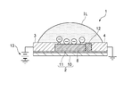
- the ionic liquid IL is placed in a hemispherical shape over the first gate electrode portion 5, the second gate electrode portion 6, the source electrode 3 and the drain electrode 4 so as to cover the entire carbon nanotube 8, and the gate insulation. It is designed to function as a layer.
- the ionic liquid IL has a hemispherical liquid surface exposed to the outside air, and the carbon nanotubes 8 at the center of the first gate electrode part 5, the second gate electrode part 6, the source electrode 3 and the drain electrode 4 are removed. It is configured to be inherent.
- the ionic liquid IL as the gas absorbing liquid is, for example, [EMIM] [BF 4 ] (1-ethyl-3-methylimidazolium tetrafluoroborate) or [BMIM] [BF 4 ] (1-butyl- 3-methylimidazolium tetrafluoroborate), [BMIM] [PF 6 ] (1-butyl-3-methylimidazolium hexafluorophosphate), [OMIM] [Br] (1-n-octyl-3-methyl Imidazolium bromide), [Hmpy] [Tf 2 N], [HMIM] [Tf 2 N], [BMIM] [Tf 2 N], [C 6 H 4 F 9 mim] [Tf 2 N], [ AMIM] [BF 4 ], [Pabim] [BF 4 ], [Am-im] [DCA], [Am-im] [BF 4 ], [BMIM] [BF 4 ] + PVDF, [C 3 NH 2 mim ] [CF
- CO 2 is capable of absorbing [EMIM] [BF 4], [EMIM] [BF 4], [BMIM] [BF 4], [ BMIM] [PF 6 ], [Hmpy] [Tf 2 N], [HMIM] [Tf 2 N], [BMIM] [Tf 2 N], [C 6 H 4 F 9 mim] [Tf 2 N], [ AMIM] [BF 4 ], [Pabim] [BF 4 ], [Am-im] [DCA], [Am-im] [BF 4 ], [BMIM] [BF 4 ] + PVDF, [C 3 NH 2 mim ] [CF 6 SO 3 ] + PTFE, [C 3 NH 2 mim] [Tf 2 N] + PTFE, [H 2 NC 3 H 6 mim] [Tf 2 N] + cross-linked Nylon66, P [VBBI] [ BF 4 ], P [MABI] [BF 4 ], P [VBBI] [Tf
- PEI polyethyleneimine
- the amino group of PEI can transfer electric charge to the carbon nanotubes 8 and the resistance value of the carbon nanotubes 8 can be reduced.
- PEI when gas is absorbed, PEI reacts with CO 2 and H 2 O, and the amino group of PEI decreases.
- the ionic liquid IL absorbs outside air having a high CO 2 content
- the amino group of the PEI in the ionic liquid IL is reduced, and as a result,
- the resistance value of the carbon nanotube 8 can be increased, and the electrical state of the carbon nanotube 8 can be changed according to the content of CO 2 in the outside air.
- the ionic liquid IL is applied as the gas absorbing liquid.
- the present invention is not limited to this, for example, hydroxide aqueous solutions of alkali metals and alkaline earth metals, and the like.
- Various gas absorbing liquids may be applied. Note that, when an alkali metal and alkaline earth metal hydroxide aqueous solution is used as the gas absorbing liquid, CO 2 can be absorbed, so that a gas sensor with CO 2 as a detection target can be realized.
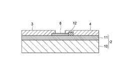
- the ionic liquid IL is placed as shown in FIG. 3 showing the sectional configuration of the AA ′ portion in FIG. 2 and FIG. 4 showing the sectional configuration of the BB ′ portion in FIG.
- the substrate 2 has a configuration in which a silicon oxide film 11 is formed on a silicon substrate 10, and a source electrode 3, a drain electrode 4, a first gate electrode portion 5 and a second gate electrode portion 6 are formed on the silicon oxide film 11. Is provided.
- the carbon nanotube 8 has one end side covered with the source electrode 3 and the other end side covered with the drain electrode 4.
- the carbon nanotube 8 is electrically connected to the source electrode 3 and the drain electrode 4. It is comprised so that it can connect to.
- the carbon nanotubes 8 can be securely fixed to the substrate 2 by covering both ends with the source electrode 3 and the drain electrode 4 in this way, and thus when the ionic liquid IL is dropped, the substrate 2 Therefore, the electrical connection state to the source electrode 3 and the drain electrode 4 can be maintained as it is.
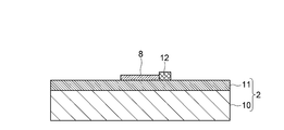
- Such carbon nanotubes 8 have a diameter of about 1 to 10 nm, and are formed to grow linearly along the silicon oxide film 11 from the catalyst portion 12 provided on the silicon oxide film 11.
- the catalyst unit 12 is made of, for example, a member in which Co and silica are mixed at a predetermined ratio, and is covered with the drain electrode 4 together with the other end of the carbon nanotube 8.
- a source / drain current is supplied from a source electrode 3 to a drain electrode 4 by a power source 13 as shown in FIG. 3, and a first gate electrode portion 5 is supplied by a power source 15 as shown in FIG.
- a gate voltage can be applied to the second gate electrode portion 6.
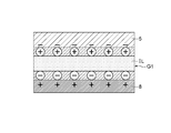
- the ionic liquid IL when a negative voltage is applied to the gate electrode 7, in the gas sensor 1, as shown in FIG. 5, the anions in the ionic liquid IL gather on the side peripheral surface of the carbon nanotube 8 and the first gate electrode portion 5. Cations in the ionic liquid IL gather in the second gate electrode portion 6 (the same applies to the second gate electrode portion 6), and in the ionic liquid IL, an electric double layer (in FIG. 5, a layer in which a symbol surrounded by-is marked, and + is 2), the ionic liquid IL can be a gate insulating layer.
- the gate voltage Vg is applied to the first gate electrode portion 5 and the second gate electrode portion 6, and the source / drain voltage V sd is applied between the source electrode 3 and the drain electrode 4.
- an extremely thin gate insulating layer is formed in the ionic liquid IL, and a source / drain current I sd flows through the carbon nanotubes 8 to operate as a transistor.
- the state of the gate insulating layer in the ionic liquid IL may change according to the amount of gas absorbed.
- the source / drain current / gate voltage characteristics can also be changed according to the state change of the gate insulating layer.
- the gas sensor 1 measures such a change in source / drain current / gate voltage characteristics, and can detect a gas to be detected based on the change in the source / drain current / gate voltage characteristics. Further, in this gas sensor 1, the amount of change in the source / drain current / gate voltage characteristics is measured, and when the amount of change is large, the gas concentration in the gas around the ionic liquid IL (hereinafter also referred to simply as outside air) is high. On the other hand, when the amount of change is small, it indicates that the gas concentration in the outside air is low, and the gas concentration in the outside air can be estimated.
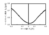
- the gas sensor 1 has a source-drain current I sd and a current when the gas around the ionic liquid IL does not contain the gas to be detected as shown in FIG. relation between the gate voltage V g is the waveform obtained nearly V-shape.
- the gas concentration is detected in the gas surrounding the ionic liquid IL is high, can shift the gate voltage V g in the gas sensor 1 is shifted voltage V Shift.
- the shift voltage V shift can increase in proportion to the increase in the gas concentration in the outside air.
- the gate electrode 7 is provided, the gate voltage Vg is applied to the first gate electrode portion 5 and the second gate electrode portion 6 constituting the gate electrode 7, and the ionic liquid IL
- the present invention is not limited to this, and the source / drain current I flowing in the carbon nanotube 8 between the source electrode 3 and the drain electrode 4 can be obtained by absorbing the gas without providing the gate electrode 7 and the ionic liquid IL.
- a gas sensor that simply measures the change in sd may be used.
- the carbon nanotubes 8 with many holes are in the ionic liquid IL, so that negative charges in the ionic liquid IL are generated on the surface of the carbon nanotubes 8. Gathered. Thereby, in the gas sensor 1, the state of the negative charge and the positive charge in the ionic liquid IL changes as the ionic liquid IL absorbs the gas, and the source / drain current I sd flowing through the carbon nanotube 8 also changes accordingly. Can do. Thus, in this gas sensor 1, even if the gate electrode 7 is not provided, the detection of the gas contained in the outside air and the content of the gas can be estimated from the change in the source / drain current Isd flowing through the carbon nanotube 8.
- a substrate 2 having a silicon oxide film 11 formed on a silicon substrate 10 is prepared, and a resist layer having a predetermined pattern is formed on the silicon oxide film 11.
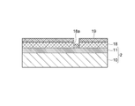
- a catalyst layer 19 is formed on the resist layer 18 of the substrate 2 by spin coating, and the catalyst is also formed on the silicon oxide film 11 exposed in the opening 18a formed in the resist layer 18.
- Layer 19 is formed.
- a catalyst material formed by mixing Co and fumed silica at 1:10 is used.
- the resist layer 18 is removed by lift-off, and only the catalyst layer 19 formed in the opening 18a is left to form a rectangular catalyst portion 12 of 3 to 7 [ ⁇ m].
- carbon is grown from the catalyst portion 12 by chemical vapor deposition (Chemical Vapor Deposition: CVD), and the carbon nanotubes 8 extending straight from the catalyst portion 12 are converted into silicon oxide films 11 as shown in FIG. Form on top.
- CVD chemical Vapor Deposition
- patterning is performed by exposure, and as shown in FIG. 9, for example, the resist layer 21 is left in the central region of the carbon nanotube 8 exposed in the ionic liquid IL, and then the entire surface is exposed.
- An electrode layer 22 made of Ti / Au (5/50) is formed.
- the resist layer 21 is removed by lift-off, and the electrode layer 22 is patterned to expose the central region of the carbon nanotube 8, as shown in FIG. 10, and the source electrode 3, the drain electrode 4, and a first electrode (not shown).
- a first gate electrode portion 5 and a second gate electrode portion 6 are formed on the silicon oxide film 11.
- ionic liquid IL is dropped on the substrate 2 so as to cover the entire carbon nanotube 8 exposed between the source electrode 3 and the drain electrode 4, as shown in FIG.
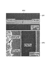
- a source electrode 3 (denoted as “Source” in the figure), a drain electrode 4 (denoted as “Drain” in the figure), a gate electrode 7 (first gate electrode part 5 and second gate electrode part 6), and “IL” in the figure
- a gas sensor 1 in which an ionic liquid IL (indicated as “Ionic ⁇ liquid” in the figure) is in contact with -gate Electrodes ”.
- FIG. 13 in which the area ER1 in FIG. 12 is enlarged and in the SEM photograph in which the area ER2 in FIG.
- the gas sensor 1 manufactured in this way is the source of the carbon nanotubes 8 that are inherent in the ionic liquid IL.
- the carbon nanotube 8 is formed in a slight gap between the electrode 3 and the drain electrode 4, and the carbon nanotube 8 has a very minute structure.
- the notation “Catalyst” in FIG. 13 indicates the catalyst portion 12 buried in the drain electrode 4, and the shape of the catalyst portion 12 can be confirmed from the drain electrode 4 located on the outside.
- the source electrode 3, the drain electrode 4, and the gate electrode 7 are each formed of Ti / Au (film thickness 5 [nm] / 50 [nm]), and Co and fumed silica are 1 :
- the carbon nanotube 8 is formed from the catalyst part 12 formed by mixing at 10, the gap between the source electrode 3 and the drain electrode 4 is 1 [ ⁇ m], and the resistance value of the carbon nanotube 8 is 5 to 100 [k ⁇ ]
- the gas sensor 1 selected during this period was manufactured.
- the gas sensor 1 applies the source / drain current Isd flowing from the source electrode 3 to the drain electrode 4 through the carbon nanotube 8 and the gate electrode 7.
- the result shown in FIG. 14 was obtained.
- the source / drain voltage V sd between the source electrode 3 and the drain electrode 4 of the gas sensor 1 is 10 [mV]
- the gate voltage V g applied to the gate electrode 7 is ⁇ 0.3 [V] to 0.3 [V].
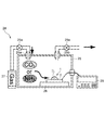
- the gas to be detected is supplied from the gas storage section 27 through the valve 29a into the chamber 25 of 300 ⁇ 300 ⁇ 100 [mm 3 ] through the supply port 25a, and the valve 29b is installed. The gas was discharged from the discharge port 25b to the outside of the chamber 25. Further, in this experimental apparatus 24, the gas sensor 1 is placed on the base 26 in the chamber 25, and the measuring device 28 provided outside the chamber 25 and the gas sensor 1 in the chamber 25 are connected to each other in a sealed state of the chamber 25. The connection was made while maintaining.
- the source / drain voltage V sd is set to 10 [mV]
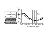
- the gate voltage V g applied to the gate electrode 7 is increased from ⁇ 0.3 [V] to 0.3 [V] by 5 [mV / sec].
- the source / drain current Isd was measured, the result shown in FIG. 17 was obtained. From FIG. 17, it can be confirmed that in the gas sensor 1 of the present invention, when CO 2 to be detected is mixed with the outside air, the gate voltage V g is shifted by ⁇ 42.9 [mV] as compared with the case of normal outside air. It was.
- the ionic liquid IL absorbs CO 2 as a detection target, and as a result, the state of the gate insulating layer formed in the ionic liquid IL changes, and the source / drain current Isd changes and the shift voltage changes. It was confirmed that V shift occurred. Thus, it was confirmed that the gas sensor 1 of the present invention can detect CO 2 in the outside air around the ionic liquid IL by measuring the change in the source / drain current I sd .
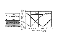
- the ionic liquid IL absorbs NH 3 as a detection target, and as a result, the state of the gate insulating layer formed in the ionic liquid IL changes, and the source / drain current I sd changes and the shift voltage changes. It was confirmed that V shift occurred. Thus, it was confirmed that the gas sensor 1 of the present invention can detect NH 3 in the outside air around the ionic liquid IL by measuring the change in the source / drain current Isd .
- the NH 3 concentration was changed to 40 to 4000 [ppm], and the shift voltage V shift was measured, and the result shown in FIG. 19 was obtained. From FIG. 19, it can be confirmed that in this gas sensor 1, the shift voltage V shift changes linearly with respect to the concentration log of NH 3 , and from this, the change of the shift voltage V shift caused by the change of the source / drain current Isd Based on this, it was also confirmed that the NH 3 concentration could be estimated.
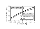
- ionic liquid IL in which PEI (branched, MW10,000) is mixed with [EMIM] [BF 4 ] is used as ionic liquid IL, and metallic carbon nanotube is used as carbon nanotube 8.
- a gas sensor 1 was prepared. Incidentally, whether it is a metallic carbon nanotube or a semiconductor carbon nanotube, which will be described later, was determined from the shape of the curve by measuring the IV characteristic after the carbon nanotube 8 was formed.
- the source / drain voltage V sd of the gas sensor 1 is set to 10 [mV]
- the source / drain current I sd is between the gate voltage V g ⁇ 0.3 [V] and 0.3 [V].
- the ionic liquid IL which is the same as the above [EMIM] [BF 4 ] mixed with PEI (branched, MW10,000), is used as the ionic liquid IL, and the semiconductor carbon nanotube is used as the carbon nanotube 8.
- a gas sensor 1 was prepared.
- the source / drain voltage V sd of the gas sensor 1 is set to 10 [mV]
- the source / drain current I sd is between the gate voltage V g ⁇ 0.3 [V] and 0.3 [V].
- the gas sensor 1 is configured such that the carbon nanotube 8 is provided between the source electrode 3 and the drain electrode 4 on the substrate 2 and the carbon nanotube 8 is covered with the ionic liquid IL. .
- the carbon nanotubes 8 with many holes are in the ionic liquid IL, the negative charges in the ionic liquid IL are collected on the surface of the carbon nanotubes 8.
- the state of the negative charges collected on the surface of the carbon nanotubes 8 in the ionic liquid IL changes, and the source flowing to the carbon nanotubes 8 accordingly. Since the drain current I sd also changes, the gas in the outside air can be detected based on the change tendency of the source / drain current I sd .
- a carbon nanotube 8 is provided between the source electrode 3 and the drain electrode 4 on the substrate 2, and the ionic liquid serving as a gate insulating layer in contact with the carbon nanotube 8 and the gate electrode 7 on the substrate 2 IL is provided, and a gate voltage is applied to the ionic liquid IL via the gate electrode 7.
- an electric double layer having a gate insulating layer is formed in the ionic liquid IL that absorbs the gas, and the gas sensor 1 can be operated as a transistor capable of measuring the source / drain current Isd flowing through the carbon nanotube 8.
- a film thickness of, for example, 150 to 200 [nm] is used as a gate insulating layer between the silicon back gate and the carbon nanotube. Since a silicon oxide film is used, a gate voltage of about 15 [V] at maximum is required to operate as a transistor.
- an extremely thin gate insulation of several nm is formed in the ionic liquid IL provided between the carbon nanotube 8 and the gate electrode 7 without using a silicon oxide film such as SiO 2. since the layer is formed, it is possible to reduce the 0.4 even when the gate voltage V g of about [V] is applied to the gate electrode 7 can operate as a transistor, of dramatically gate voltage V g than conventional.
- this gas sensor 1 a gate insulating layer is formed in the ionic liquid IL itself that absorbs the gas, and the state change of the gate insulating layer of the ionic liquid IL caused by absorbing the gas directly flows through the carbon nanotube 8 Since it is reflected in the drain current, the gas detection sensitivity can be improved as compared with the conventional case. Further, in this gas sensor 1, since it is not necessary to perform surface chemical modification on the carbon nanotube itself as in the prior art, it is only necessary to provide the ionic liquid IL so as to contact the carbon nanotube 8 and the gate electrode 7. A simple configuration can be obtained.
- the source / drain current / gate voltage characteristics change according to the gas concentration in the outside air. Therefore, by measuring the amount of change in the source / drain current / gate voltage characteristics, the outside air is measured based on the amount of change. It is also possible to estimate how much the gas to be detected is contained.
- the carbon nanotubes 8 between the source electrode 3 and the drain electrode 4 in the ionic liquid IL, the change in the state of the electric charge in the ionic liquid IL caused by absorbing the gas directly occurs in the carbon. Since this is reflected in the source / drain current Isd flowing through the nanotube 8, the gas detection sensitivity can be improved as compared with the conventional case.
- the carbon nanotubes 8 need only be disposed in the ionic liquid IL, the conventional structure for chemically modifying the surface of the carbon nanotubes with a plurality of polymers is no longer necessary, and that much simpler. It can be configured.
- an electric double layer including a gate insulating layer is formed in the ionic liquid IL, and a change in the state of the gate insulating layer of the ionic liquid IL caused by absorbing the gas directly causes a source-drain current flowing through the carbon nanotubes 8. Since it is reflected in I sd , the gas detection sensitivity can be improved as compared with the conventional case.
- the ionic liquid IL need only be provided on the substrate 2 so as to contact the carbon nanotube 8 and the gate electrode 7, the conventional structure for chemically modifying the surface of the carbon nanotube with a plurality of polymers becomes unnecessary. Therefore, a simple configuration can be obtained.
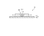
- FIG. 22 which attaches
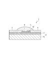
- the source electrode 3, the drain electrode 4, the first gate electrode portion 5, and the second gate without covering the upper surfaces of the source electrode 3, the drain electrode 4, the first gate electrode portion 5, and the second gate electrode portion 6.
- Application of gas sensor 31 with ionic liquid IL1 only in region G2 surrounded by electrode 6 May be.
- the source electrode 3, the drain electrode 4, the first gate electrode portion 5 and the second gate electrode portion 6 are in contact with the respective side surfaces of the source electrode 3, the drain electrode 4, and the first gate electrode portion 6, so Since the ionic liquid IL1 is arranged in the region G2 surrounded by the electrode portion 5 and the second gate electrode portion 6, the amount of the ionic liquid IL1 is reduced to reduce the size, and the ion is exerted by the action of the surface tension.
- the liquid IL1 can be stably provided on the substrate 2.
- the ionic liquid IL1 when a gate voltage is applied to the ionic liquid IL1 through the gate electrode 7, an electric double layer including a gate insulating layer of several nm in the ionic liquid IL1.
- the ionic liquid IL1 can be reduced to a volume capable of forming a gate insulating layer of about several nm of this electric double layer.
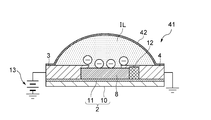
- the gas sensor 1 in which the ionic liquid IL is simply dropped and placed on the substrate 2 has been described.
- the present invention is not limited to this, and FIG. 25, the liquid surface formed in a curved shape of the ionic liquid IL is covered with a coating film 42 through which external air such as parylene can pass. A gas sensor 41 may be applied. In this case, even if an external force is applied to the substrate 2 or tilted, the ionic liquid IL is stably held on the substrate 2 by the coating film 42 as a holding means. Can continue to.
- this gas sensor 41 forms a coating on the ionic liquid IL by, for example, a CVD (Chemical Vapor Deposition) method after the ionic liquid IL is dropped, and allows the outside air such as parylene to pass through the film. It can be manufactured by forming the coating film 42 directly. Further, the gas sensor 41 is formed by previously forming a coating film 42 on the substrate 2 with a coating material through which outside air such as parylene can pass and injecting and sealing the ionic liquid IL into the coating film 42. Can also be manufactured.
- CVD Chemical Vapor Deposition
- the ionic liquid IL can be stably held on the substrate 2 by the coating film 42, for example, the substrate 2 is placed on the indoor ceiling with the ionic liquid IL facing downward.
- the ionic liquid IL can be installed in various directions according to the usage situation.
- the gas absorbing liquid can be isolated from the outside air, a volatile liquid such as water can also be used as the gas absorbing liquid. Even if water is used as the gas-absorbing liquid, the source-drain current I sd flowing through the carbon nanotubes 8 changes according to the change in the state of the charge in the water due to the water absorbing the gas, and the above-described embodiment The same effect can be obtained.
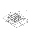
- a frame body 52 that covers the ionic liquid IL is provided on the substrate 2 as shown in FIG.
- a gas sensor 51 in which the ionic liquid IL is held on the substrate 2 by the frame 52 may be applied.
- the frame 52 covers the carbon nanotubes 8 (not shown) between the source electrode 3 and the drain electrode 4 on the substrate 2, and the source electrode 3, the drain electrode 4 disposed around the carbon nanotubes 8, It is arranged on the substrate 2 so as to cover a part of the gate electrode 7 so that the ionic liquid IL can be held in the internal space.
- the frame 52 forms an internal space with, for example, a quadrilateral wall 52a that blocks the ionic liquid IL, and a plate-shaped top plate 52b arranged to cover the wall 52a.
- a plurality of fine through holes 53 that allow communication between the internal space and the outside are formed in the top plate portion 52b.
- the frame body 52 is installed on the substrate 2 so that the bottom surface portion is closed, the internal space communicates with the outside only through the through hole 53, and the ionic liquid IL is injected from the through hole 53 into the internal space.
- the ionic liquid IL can be held in the internal space.
- the through-hole 53 is fine in the frame 52, the surface tension of the ionic liquid IL works in the through-hole 53, and the ionic liquid IL injected into the internal space flows out from the through-hole 53 to the outside. This makes it difficult to hold the ionic liquid IL reliably.
- the ionic liquid IL covers the carbon nanotubes in the internal space of the frame body 52 and is in contact with the first gate electrode portion 5 and the second gate electrode portion 6 (not shown) of the gate electrode 7.
- a substrate 2 provided with a carbon nanotube 8, a gate electrode 7 and the like is installed in a box-shaped storage part in which the ionic liquid IL is stored, and the substrate 2 is placed in the ionic liquid IL.
- a gas sensor having various configurations in which the positional relationship between the substrate 2 and the ionic liquid IL is appropriately changed may be applied depending on the use situation.
Landscapes
- Chemical & Material Sciences (AREA)
- Health & Medical Sciences (AREA)
- Life Sciences & Earth Sciences (AREA)
- Engineering & Computer Science (AREA)
- Biochemistry (AREA)
- General Health & Medical Sciences (AREA)
- Pathology (AREA)
- Immunology (AREA)
- Physics & Mathematics (AREA)
- Analytical Chemistry (AREA)
- General Physics & Mathematics (AREA)
- Electrochemistry (AREA)
- Chemical Kinetics & Catalysis (AREA)
- Molecular Biology (AREA)
- Microelectronics & Electronic Packaging (AREA)
- Combustion & Propulsion (AREA)
- Food Science & Technology (AREA)
- Medicinal Chemistry (AREA)
- Nanotechnology (AREA)
- Investigating Or Analyzing Materials By The Use Of Electric Means (AREA)
Abstract
Description
そこで、本発明は以上の点を考慮してなされたもので、簡易な構成で、従来よりもガスの検出感度を向上し得るガスセンサを提案することを目的とする。
2 基板
3 ソース電極
4 ドレイン電極
5 第1ゲート電極部
6 第2ゲート電極部
7 ゲート電極
8 カーボンナノチューブ
IL イオン液体(ガス吸収液体)
42 被覆膜(保持手段)
52 枠体(保持手段)
図1において、1は本発明によるガスセンサを示し、このガスセンサ1は、例えばCO2やNH3等のガスを検出対象として検出し得るようになされている。実際上、ガスセンサ1は、板状でなる基板2上に帯状のソース電極3及びドレイン電極4を備え、これらソース電極3及びドレイン電極4間にカーボンナノチューブ8が設けられている。これらソース電極3とドレイン電極4は、例えばTi/Au部材やCr/Au部材からなり、長手方向を揃えてほぼ直線状に配置されており、対向するソース電極3の端部とドレイン電極4の端部との間に約1μmの隙間が形成されている。
次に本発明のガスセンサ1の製造方法について説明する。この実施の形態の場合、先ず初めに、シリコン基板10上にシリコン酸化膜11が形成された基板2を用意し、当該シリコン酸化膜11上に所定パターンのレジスト層を形成する。次いで、図7に示すように、基板2のレジスト層18上に触媒層19をスピンコートにより形成し、当該レジスト層18に形成した開口18a内にて露出させたシリコン酸化膜11上にも触媒層19を形成する。なお、この触媒層19は、例えばCoとヒュームドシリカとを1:10で混合させて形成した触媒材料等を用いる。次いで、リフトオフによりレジスト層18を除去して、開口18a内に形成された触媒層19だけを残存させて3~7[μm]の矩形状の触媒部12を形成する。
次に各種検証試験について説明する。ここでは、上述した製造方法に従って、ソース電極3、ドレイン電極4、ゲート電極7をそれぞれTi/Au(膜厚5[nm]/50[nm])で形成し、Coとヒュームドシリカとを1:10で混合して形成した触媒部12からカーボンナノチューブ8を形成し、また、ソース電極3及びドレイン電極4間の隙間を1[μm]、カーボンナノチューブ8の抵抗値を5~100[kΩ]の間に選定したガスセンサ1を製造した。そして、検出対象であるガスが外気に含まれていないとき、このガスセンサ1にてソース電極3からカーボンナノチューブ8を通ってドレイン電極4へ流れるソースドレイン電流Isdと、ゲート電極7に印加されるゲート電圧Vgとの関係を調べたところ、図14に示すような結果が得られた。
以上の構成において、このガスセンサ1では、基板2上のソース電極3及びドレイン電極4間にカーボンナノチューブ8を設け、このカーボンナノチューブ8をイオン液体ILにより覆うような構成とした。このようなガスセンサ1では、ホールが多いカーボンナノチューブ8がイオン液体IL中にあることにより、イオン液体IL中の負電荷がカーボンナノチューブ8の表面に集まる。これにより、ガスセンサ1では、イオン液体ILが検出対象たるガスを吸収すると、イオン液体IL中でカーボンナノチューブ8の表面に集まっている負電荷の状態が変化し、これに伴いカーボンナノチューブ8に流れるソースドレイン電流Isdも変化することから、このソースドレイン電流Isdの変化の傾向に基づいて外気中のガスを検出することができる。
なお、本発明は、本実施形態に限定されるものではなく、本発明の要旨の範囲内で種々の変形実施が可能であり、上述した実施の形態においては、ソース電極3及びドレイン電極4上だけでなく、第1ゲート電極部5及び第2ゲート電極部6上に載置されるようにイオン液体ILを設けたガスセンサ1について述べたが、本発明はこれに限らず、図1との対応部分に同一符号を付して示す図22と、図22のC-C´部分の断面構成を示す図23と、図22のD-D´部分の断面構成を示す図24のように、ソース電極3、ドレイン電極4、第1ゲート電極部5及び第2ゲート電極部6の上面を覆うことなく、ソース電極3とドレイン電極4と第1ゲート電極部5と第2ゲート電極部6とに囲まれた領域G2にだけイオン液体IL1を設けたガスセンサ31を適用してもよい。
Claims (8)
- 検出対象となるガスを検出するガスセンサであって、
基板上のソース電極及びドレイン電極間に設けられ、ソースドレイン電流が流れるカーボンナノチューブと、
前記カーボンナノチューブを覆うように配置されたガス吸収液体とを備え、
前記ガス吸収液体が前記ガスを吸収することにより前記カーボンナノチューブに生じるソースドレイン電流の変化に基づいて前記ガスを検出する
ことを特徴とするガスセンサ。 - 前記ガス吸収液体は、前記カーボンナノチューブと前記基板上のゲート電極とに接してゲート絶縁層になり、前記ガスを吸収することにより前記ゲート絶縁層の状態が変化し、該ゲート絶縁層の状態に応じて生じる前記ソースドレイン電流の変化に基づいて前記ガスを検出する
ことを特徴とする請求項1記載のガスセンサ。 - 前記ゲート電極は第1ゲート電極部と第2ゲート電極部とから構成されており、
前記第1ゲート電極部と第2ゲート電極部との間に前記カーボンナノチューブが配置され、前記ガス吸収液体が前記第1ゲート電極部及び前記第2ゲート電極部と接するように配置されている
ことを特徴とする請求項2記載のガスセンサ。 - 前記ガス吸収液体が前記第1ゲート電極部及び前記第2ゲート電極部間に形成される隙間に保持されている
ことを特徴とする請求項3記載のガスセンサ。 - 前記ガス吸収液体を覆い、該ガス吸収液体を前記基板上に保持させる保持手段が設けられている
ことを特徴とする請求項1~4のうちいずれか1項記載のガスセンサ。 - 前記ソースドレイン電流に対応して変化する前記ゲート電極のゲート電圧の変化に基づいて前記ガスを検出する
ことを特徴とする請求項2~5のうちいずれか1項記載のガスセンサ。 - 前記ガス吸収液体がイオン液体である
ことを特徴とする請求項1~6のうちいずれか1項記載のガスセンサ。 - 前記ガス吸収液体が、アルカリ金属及びアルカリ土類金属の水酸化物水溶液である
ことを特徴とする請求項1~6のうちいずれか1項記載のガスセンサ。
Priority Applications (5)
| Application Number | Priority Date | Filing Date | Title |
|---|---|---|---|
| CN201280060963.XA CN103988071A (zh) | 2012-01-13 | 2012-12-27 | 气体传感器 |
| US14/366,912 US9250210B2 (en) | 2012-01-13 | 2012-12-27 | Gas sensor |
| EP12864780.7A EP2803984B1 (en) | 2012-01-13 | 2012-12-27 | Gas sensor |
| JP2013553247A JP5822282B2 (ja) | 2012-01-13 | 2012-12-27 | ガスセンサ |
| KR1020147015752A KR20140089432A (ko) | 2012-01-13 | 2012-12-27 | 가스 센서 |
Applications Claiming Priority (2)
| Application Number | Priority Date | Filing Date | Title |
|---|---|---|---|
| JP2012004963 | 2012-01-13 | ||
| JP2012-004963 | 2012-01-13 |
Publications (1)
| Publication Number | Publication Date |
|---|---|
| WO2013105449A1 true WO2013105449A1 (ja) | 2013-07-18 |
Family
ID=48781405
Family Applications (1)
| Application Number | Title | Priority Date | Filing Date |
|---|---|---|---|
| PCT/JP2012/083879 Ceased WO2013105449A1 (ja) | 2012-01-13 | 2012-12-27 | ガスセンサ |
Country Status (6)
| Country | Link |
|---|---|
| US (1) | US9250210B2 (ja) |
| EP (1) | EP2803984B1 (ja) |
| JP (1) | JP5822282B2 (ja) |
| KR (1) | KR20140089432A (ja) |
| CN (1) | CN103988071A (ja) |
| WO (1) | WO2013105449A1 (ja) |
Cited By (5)
| Publication number | Priority date | Publication date | Assignee | Title |
|---|---|---|---|---|
| WO2014104156A1 (ja) * | 2012-12-28 | 2014-07-03 | 国立大学法人東京大学 | ガスセンサ及びガスセンサ構造体 |
| GB2523173A (en) * | 2014-02-17 | 2015-08-19 | Nokia Technologies Oy | An apparatus and associated methods |
| WO2017168570A1 (ja) * | 2016-03-29 | 2017-10-05 | 三菱電機株式会社 | 空調機 |
| JP2017194295A (ja) * | 2016-04-18 | 2017-10-26 | 株式会社東海理化電機製作所 | バイオセンサ |
| JP2022169933A (ja) * | 2021-04-28 | 2022-11-10 | 東レ株式会社 | ガスセンサー素子およびガスセンサー |
Families Citing this family (21)
| Publication number | Priority date | Publication date | Assignee | Title |
|---|---|---|---|---|
| EP3041785A1 (en) | 2013-09-06 | 2016-07-13 | Massachusetts Institute of Technology | Devices and methods including a preconcentrator material for detection of analytes |
| EP3041597B1 (en) | 2013-09-06 | 2022-11-02 | Massachusetts Institute of Technology | Filter materials including functionalized cellulose |
| IL252498A0 (en) * | 2017-05-24 | 2017-07-31 | Technion Res & Dev Foundation | Carbon dioxide detectors containing polymeric ionic liquid |
| CN107219287B (zh) * | 2017-06-28 | 2023-11-17 | 汉威科技集团股份有限公司 | 离子液体电化学气体传感器 |
| US12196636B2 (en) | 2019-03-27 | 2025-01-14 | Lyten, Inc. | Sensors incorporated into airborne vehicle components to detect physical characteristic changes |
| US11592279B2 (en) | 2019-03-27 | 2023-02-28 | Lyten, Inc. | Sensors incorporated into elastomeric materials to detect environmentally-caused physical characteristic changes |
| US11719582B2 (en) | 2019-03-27 | 2023-08-08 | Lyten, Inc. | Sensors incorporated into tire plies to detect reversible deformation and/or temperature changes |
| US11656070B2 (en) | 2019-03-27 | 2023-05-23 | Lyten, Inc. | Systems for detecting physical property changes in an elastomeric material |
| US12317466B2 (en) | 2019-03-27 | 2025-05-27 | Lyten, Inc. | Frequency selective metamaterial for protective enclosures |
| US11555748B2 (en) | 2019-03-27 | 2023-01-17 | Lyten, Inc. | Sensors incorporated into tire plies to detect reversible deformation and/or temperature changes |
| US12265058B2 (en) | 2019-03-27 | 2025-04-01 | Lyten, Inc. | Sensors incorporated into adhesive material |
| US11555761B1 (en) | 2019-03-27 | 2023-01-17 | Lyten, Inc. | Sensors incorporated into elastomeric components to detect physical characteristic changes |
| US11585731B2 (en) | 2019-03-27 | 2023-02-21 | Lyten, Inc. | Sensors incorporated into semi-rigid structural members to detect physical characteristic changes |
| US12339272B2 (en) | 2019-03-27 | 2025-06-24 | Lyten, Inc. | Sensors incorporated into building materials to detect physical characteristic changes |
| US12270785B2 (en) | 2019-03-27 | 2025-04-08 | Lyten, Inc. | Water droplet sensing systems and methods |
| US11965803B2 (en) | 2019-03-27 | 2024-04-23 | Lyten, Inc. | Field deployable resonant sensors |
| US12313570B2 (en) | 2019-03-27 | 2025-05-27 | Lyten, Inc. | Leaky coaxial resonant sensor systems and methods |
| CN110596222A (zh) * | 2019-09-16 | 2019-12-20 | 北京大学 | 一种碳纳米管场效应晶体管型传感器及其制备方法 |
| EP4491573A3 (en) * | 2020-02-20 | 2025-03-19 | Lyten, Inc. | Analyte sensing device |
| KR102652552B1 (ko) * | 2022-02-24 | 2024-03-29 | 단국대학교 산학협력단 | 산화갈륨을 이용한 가스 센서 |
| US20240275608A1 (en) | 2023-02-15 | 2024-08-15 | Lyten, Inc. | Method to learn precise sensing fingerprints based on machine learning integration |
Citations (8)
| Publication number | Priority date | Publication date | Assignee | Title |
|---|---|---|---|---|
| JPH02138857A (ja) * | 1988-11-18 | 1990-05-28 | Shindengen Electric Mfg Co Ltd | ガスセンサ |
| JPH03237350A (ja) * | 1990-02-14 | 1991-10-23 | Terumo Corp | pHセンサーおよびその製造方法 |
| JPH04223B2 (ja) * | 1983-12-09 | 1992-01-06 | Nippon Koden Kogyo Kk | |
| JPH0679009B2 (ja) * | 1985-11-22 | 1994-10-05 | 株式会社東芝 | 化学センサ |
| JP2004085392A (ja) * | 2002-08-27 | 2004-03-18 | Fujitsu Ltd | 炭素元素線状構造体を用いた電界効果トランジスタ化学センサー |
| JP2006222279A (ja) * | 2005-02-10 | 2006-08-24 | Japan Science & Technology Agency | n型トランジスタ、n型トランジスタセンサ及びn型トランジスタ用チャネルの製造方法 |
| JP2007505323A (ja) | 2003-09-12 | 2007-03-08 | ナノミックス・インコーポレーテッド | 二酸化炭素用ナノ電子センサー |
| JP2010192599A (ja) * | 2009-02-17 | 2010-09-02 | Olympus Corp | カーボンナノ材料を用いた電界効果トランジスタにおける絶縁膜成膜方法及びカーボンナノ材料を用いた電界効果トランジスタ |
Family Cites Families (8)
| Publication number | Priority date | Publication date | Assignee | Title |
|---|---|---|---|---|
| CA1251514A (en) * | 1985-02-20 | 1989-03-21 | Tadashi Sakai | Ion selective field effect transistor sensor |
| US8154093B2 (en) * | 2002-01-16 | 2012-04-10 | Nanomix, Inc. | Nano-electronic sensors for chemical and biological analytes, including capacitance and bio-membrane devices |
| US20070048181A1 (en) * | 2002-09-05 | 2007-03-01 | Chang Daniel M | Carbon dioxide nanosensor, and respiratory CO2 monitors |
| US6949931B2 (en) * | 2002-11-26 | 2005-09-27 | Honeywell International Inc. | Nanotube sensor |
| JP5369755B2 (ja) | 2009-02-25 | 2013-12-18 | 株式会社豊田中央研究所 | ガスセンサ |
| JP2010203838A (ja) | 2009-03-02 | 2010-09-16 | Sonac Kk | 光導波路型センサ |
| JP2010261793A (ja) | 2009-05-01 | 2010-11-18 | Kurabo Ind Ltd | 液体中の溶存物質含有量測定方法及び測定装置、並びに、エッチング液再生システム |
| WO2011155179A1 (ja) | 2010-06-10 | 2011-12-15 | コニカミノルタホールディングス株式会社 | 分析素子チップ |
-
2012
- 2012-12-27 EP EP12864780.7A patent/EP2803984B1/en not_active Not-in-force
- 2012-12-27 US US14/366,912 patent/US9250210B2/en not_active Expired - Fee Related
- 2012-12-27 WO PCT/JP2012/083879 patent/WO2013105449A1/ja not_active Ceased
- 2012-12-27 CN CN201280060963.XA patent/CN103988071A/zh active Pending
- 2012-12-27 JP JP2013553247A patent/JP5822282B2/ja not_active Expired - Fee Related
- 2012-12-27 KR KR1020147015752A patent/KR20140089432A/ko not_active Ceased
Patent Citations (8)
| Publication number | Priority date | Publication date | Assignee | Title |
|---|---|---|---|---|
| JPH04223B2 (ja) * | 1983-12-09 | 1992-01-06 | Nippon Koden Kogyo Kk | |
| JPH0679009B2 (ja) * | 1985-11-22 | 1994-10-05 | 株式会社東芝 | 化学センサ |
| JPH02138857A (ja) * | 1988-11-18 | 1990-05-28 | Shindengen Electric Mfg Co Ltd | ガスセンサ |
| JPH03237350A (ja) * | 1990-02-14 | 1991-10-23 | Terumo Corp | pHセンサーおよびその製造方法 |
| JP2004085392A (ja) * | 2002-08-27 | 2004-03-18 | Fujitsu Ltd | 炭素元素線状構造体を用いた電界効果トランジスタ化学センサー |
| JP2007505323A (ja) | 2003-09-12 | 2007-03-08 | ナノミックス・インコーポレーテッド | 二酸化炭素用ナノ電子センサー |
| JP2006222279A (ja) * | 2005-02-10 | 2006-08-24 | Japan Science & Technology Agency | n型トランジスタ、n型トランジスタセンサ及びn型トランジスタ用チャネルの製造方法 |
| JP2010192599A (ja) * | 2009-02-17 | 2010-09-02 | Olympus Corp | カーボンナノ材料を用いた電界効果トランジスタにおける絶縁膜成膜方法及びカーボンナノ材料を用いた電界効果トランジスタ |
Non-Patent Citations (2)
| Title |
|---|
| A. STAR; T. R. HAN; V. JOSHI; J. C. P. GABRIEL; G. GRUNER: "Nanoelectronic Carbon Dioxide Sensors", ADVANCED MATERIALS, vol. 16, no. 22, 2004, XP002480061, DOI: doi:10.1002/adma.200400322 |
| See also references of EP2803984A4 |
Cited By (8)
| Publication number | Priority date | Publication date | Assignee | Title |
|---|---|---|---|---|
| WO2014104156A1 (ja) * | 2012-12-28 | 2014-07-03 | 国立大学法人東京大学 | ガスセンサ及びガスセンサ構造体 |
| JPWO2014104156A1 (ja) * | 2012-12-28 | 2017-01-12 | 国立大学法人 東京大学 | ガスセンサ及びガスセンサ構造体 |
| GB2523173A (en) * | 2014-02-17 | 2015-08-19 | Nokia Technologies Oy | An apparatus and associated methods |
| JP2017508958A (ja) * | 2014-02-17 | 2017-03-30 | ノキア テクノロジーズ オーユー | 装置および関連する方法 |
| US9989488B2 (en) | 2014-02-17 | 2018-06-05 | Nokia Technologies Oy | Field-effect sensor and associated methods |
| WO2017168570A1 (ja) * | 2016-03-29 | 2017-10-05 | 三菱電機株式会社 | 空調機 |
| JP2017194295A (ja) * | 2016-04-18 | 2017-10-26 | 株式会社東海理化電機製作所 | バイオセンサ |
| JP2022169933A (ja) * | 2021-04-28 | 2022-11-10 | 東レ株式会社 | ガスセンサー素子およびガスセンサー |
Also Published As
| Publication number | Publication date |
|---|---|
| CN103988071A (zh) | 2014-08-13 |
| EP2803984A4 (en) | 2015-08-12 |
| US20140346042A1 (en) | 2014-11-27 |
| JPWO2013105449A1 (ja) | 2015-05-11 |
| EP2803984B1 (en) | 2017-09-13 |
| JP5822282B2 (ja) | 2015-11-24 |
| EP2803984A1 (en) | 2014-11-19 |
| KR20140089432A (ko) | 2014-07-14 |
| US9250210B2 (en) | 2016-02-02 |
Similar Documents
| Publication | Publication Date | Title |
|---|---|---|
| JP5822282B2 (ja) | ガスセンサ | |
| WO2014104156A1 (ja) | ガスセンサ及びガスセンサ構造体 | |
| Ko et al. | Recovery improvement for large-area tungsten diselenide gas sensors | |
| Qin et al. | Microfabricated electrochemical pH and free chlorine sensors for water quality monitoring: Recent advances and research challenges | |
| US10191008B2 (en) | Gas sensor with solid electrolyte having water vapor diffusion barrier coating | |
| Huang et al. | Electrical gas sensors based on structured organic ultra-thin films and nanocrystals on solid state substrates | |
| US8384409B2 (en) | Ultra-thin organic TFT chemical sensor, making thereof, and sensing method | |
| JP2011203256A (ja) | センシング用アモルファス薄膜 | |
| EP2745102B1 (en) | Chemical sensor based on highly organized single walled carbon nanotube networks | |
| US20170110678A1 (en) | Dual-gate chemical field effect transistor sensor | |
| JPH0321063B2 (ja) | ||
| Zhou et al. | High performance gas sensors with dual response based on organic ambipolar transistors | |
| Wei et al. | Semiconductor nanowire arrays for high‐performance miniaturized chemical sensing | |
| Lienerth et al. | Improving the selectivity to polar vapors of OFET-based sensors by using the transfer characteristics hysteresis response | |
| WO2017047041A1 (ja) | 化学物質濃縮器および化学物質検出装置 | |
| Chen et al. | Gas sensing properties of surface acoustic wave NH3 gas sensor based on Pt doped polypyrrole sensitive film | |
| US20190120787A1 (en) | Graphene-based sensor and method of fabricating same | |
| Kiga et al. | CNT-FET gas sensor using a functionalized ionic liquid as gate | |
| JP6536592B2 (ja) | ガスセンサ及びセンサ装置 | |
| Chen et al. | Electronic nano sponge breath ammonia sensors using hygroscopic polymers on vertical channel nano-porous structure | |
| Chandresh et al. | Metal‐Organic Framework Thin Films Grown on Functionalized Graphene as Solid‐State Ion‐Gated FETs | |
| WO2022202523A1 (ja) | ガスセンサ | |
| Mubashshir Hasan Farooqi et al. | Gas Sensing Properties, Applications of Metal Oxide Thin Film Transistors | |
| KR20150107364A (ko) | 유중 수소 감지 센서 | |
| Luo et al. | Tailored ZnCu Conductive MOF as a Floating-Gate in Carbon Nanotube Network FET NH3 Sensors |
Legal Events
| Date | Code | Title | Description |
|---|---|---|---|
| 121 | Ep: the epo has been informed by wipo that ep was designated in this application |
Ref document number: 12864780 Country of ref document: EP Kind code of ref document: A1 |
|
| ENP | Entry into the national phase |
Ref document number: 2013553247 Country of ref document: JP Kind code of ref document: A |
|
| ENP | Entry into the national phase |
Ref document number: 20147015752 Country of ref document: KR Kind code of ref document: A |
|
| WWE | Wipo information: entry into national phase |
Ref document number: 14366912 Country of ref document: US |
|
| REEP | Request for entry into the european phase |
Ref document number: 2012864780 Country of ref document: EP |
|
| WWE | Wipo information: entry into national phase |
Ref document number: 2012864780 Country of ref document: EP |
|
| NENP | Non-entry into the national phase |
Ref country code: DE |