WO2013108382A1 - Dispositif amortisseur pour piano droit - Google Patents
Dispositif amortisseur pour piano droit Download PDFInfo
- Publication number
- WO2013108382A1 WO2013108382A1 PCT/JP2012/050985 JP2012050985W WO2013108382A1 WO 2013108382 A1 WO2013108382 A1 WO 2013108382A1 JP 2012050985 W JP2012050985 W JP 2012050985W WO 2013108382 A1 WO2013108382 A1 WO 2013108382A1
- Authority
- WO
- WIPO (PCT)
- Prior art keywords
- damper
- lever
- string
- head
- rear end
- Prior art date
- Legal status (The legal status is an assumption and is not a legal conclusion. Google has not performed a legal analysis and makes no representation as to the accuracy of the status listed.)
- Ceased
Links
Images


Classifications
-
- G—PHYSICS
- G10—MUSICAL INSTRUMENTS; ACOUSTICS
- G10C—PIANOS, HARPSICHORDS, SPINETS OR SIMILAR STRINGED MUSICAL INSTRUMENTS WITH ONE OR MORE KEYBOARDS
- G10C3/00—Details or accessories
- G10C3/16—Actions
- G10C3/161—Actions specially adapted for upright pianos
-
- G—PHYSICS
- G10—MUSICAL INSTRUMENTS; ACOUSTICS
- G10C—PIANOS, HARPSICHORDS, SPINETS OR SIMILAR STRINGED MUSICAL INSTRUMENTS WITH ONE OR MORE KEYBOARDS
- G10C1/00—General design of pianos, harpsichords, spinets or similar stringed musical instruments with one or more keyboards
- G10C1/02—General design of pianos, harpsichords, spinets or similar stringed musical instruments with one or more keyboards of upright pianos
-
- G—PHYSICS
- G10—MUSICAL INSTRUMENTS; ACOUSTICS
- G10C—PIANOS, HARPSICHORDS, SPINETS OR SIMILAR STRINGED MUSICAL INSTRUMENTS WITH ONE OR MORE KEYBOARDS
- G10C3/00—Details or accessories
- G10C3/16—Actions
- G10C3/166—Actions for damping the strings
-
- G—PHYSICS
- G10—MUSICAL INSTRUMENTS; ACOUSTICS
- G10C—PIANOS, HARPSICHORDS, SPINETS OR SIMILAR STRINGED MUSICAL INSTRUMENTS WITH ONE OR MORE KEYBOARDS
- G10C9/00—Methods, tools or materials specially adapted for the manufacture or maintenance of musical instruments covered by this subclass
Definitions
- the present invention relates to a damper device for an upright piano.
- Patent Document 1 Japanese Patent Application Laid-Open No. 2001-343969
- the damper itself is composed of a damper lever, a damper wire provided at one end thereof, and a damper provided at the tip of the damper wire.
- the damper is pivotally supported at the center of the damper lever by a damper flange provided on a center rail provided between brackets installed on a fixed part such as a piano shelf.
- the damper is provided with a damper spring between the damper lever and the damper flange, the damper lever is always pressed, and the damper provided at the tip is urged in the direction of pressing the string.
- the whippen is pivotally supported in the whippen frenzy, the whippen is rotated through the capstan 4 by keystroke of the keyboard, and the bat is pushed up by the jack supported by the whippen and pivoted on the bat. Turn the supported hammer and hit the string.
- the damper spoon provided at the rear end thereof presses the damper lever against the urging force of the damper spring, and the damper is separated from the string with which the damper is in press contact. Therefore, the strings are released and a piano sound is generated when the strings are struck.
- the strings used for pianos are usually composed of one string for bass, two strings for low and medium sounds, and three strings for medium and high sounds. Yes.
- the portion that hits the string at that time becomes a groove, the groove portion is hardened, and the other peak portion is soft.
- the damper of the upright piano has a structure in which the groove hits the single string, but in the case of two strings or three strings, it enters between the strings and produces a silencing effect.
- a soft pedal is provided, and by using the soft pedal, the configuration of the action is configured to slide in the horizontal direction, the hammer moves in the horizontal direction, and the felt mountain portion of the hammer head The sound hits the string and becomes soft.
- the damper is formed integrally with the action, so that neither the action nor the damper can be slid sideways. Further, in the upright piano, in order to emit a weak sound, the position of the hammer is changed, the hammer is moved forward, and the rotation distance is shortened to produce a soft tone (see, for example, Patent Document 3). ).
- the weak point in this conventional upright piano is that the hammer is rotated by pressing the damper lever by pressing the damper lever with the spoon on the whippen when the key is pressed. It is in the point formed integrally with the structure which pushes a lever.
- the present invention does not require various complicated mechanisms in the upright piano, and by providing a mechanism that is easy to use, the upright piano can be configured separately from the action and the damper device.
- the damper device and the action can be configured separately, and therefore the action can be configured to move away from the damper device, and the portion hitting the string of the hammer can be moved in the same manner as the action movement of the grand piano.
- the purpose is to produce a soft sound.
- this damper device allows the damper to return to its old position under its own weight and hold down the strings without using the biasing force of the spring, so that it does not give the player a so-called springy feel.
- the purpose is to give the same playing feeling as a grand piano.
- an object of the present invention is to make the damper device independent from the operation of the whippen and the action mechanism in the upright piano, and to obtain the configuration thereof.
- the present invention proposes the following configuration.
- the damper head comes into contact with the string stretched in the vertical direction to stop the sound, and the damper lever that supports the damper head by rotating the key is rotated.
- a damper device for an upright piano in which a damper head is separated from a string, wherein the damper lever is pivotally supported by an immovable damper flange provided in front of the string and a protruding portion is provided at the rear end of the keyboard.
- a damper device for an upright piano characterized in that the upper portion of the projection is opposed to the lower portion of the damper lever.
- one end portion of the damper lever integrally connected with the damper head is pivotally supported by the pivot pin so as to be pivoted to the stationary damper flange provided in front of the string.
- a damper device for an upright piano which is disposed between the pivot pin and the string and urges the damper head against the string in the contact direction by the weight of the damper head and the damper lever.
- the damper wire having the damper head at the upper end is planted at the rear end portion of the damper lever, and the front end portion of the damper lever is turned to the stationary damper flange provided at the front of the string.
- Upright piano damper device characterized by being pivotally supported.
- the damper flange is supported by a Japanese suspension arm so as to move in the lateral direction, and the damper lever is supported directly on the rear end portion of the damper lever or the damper lever upright portion via the damper wire or
- the damper head is integrally provided without being interposed, and a protruding portion is provided at the rear end portion of the keyboard, and the protruding portion is opposed to the rear end portion of the damper lever or the lower end of the damper lever upright portion.
- Upright piano damper device according to claim 1.
- the damper lever having the damper head integrally connected to the upper end is pivotally supported by the pivot pin on the stationary damper flange provided in front of the string at the center thereof.
- a damper device for an upright piano wherein the damper head and the damper lever are supported and urged in the contact direction against the string by the weight of the damper head.
- the damper wire or the damper lever for supporting the damper head is rotated on the damper flange provided on the damper rail provided on the fixing portion such as the shelf board or the bracket of the main body of the upright piano. Because it is pivotally supported, and a protruding part is provided at the rear end of the keyboard, and the protruding part is opposed to the lower part of the damper lever, the operation of the damper head is completely different from the operation of the hammer,
- the damper device could have an independent configuration that had nothing to do with the whippen in action to activate the hammer.
- the damper device is installed at a fixed position, while the action can be configured to be movable in the left-right direction on the cage. If this configuration can be adopted, the action for producing a soft sound can be moved by adopting the pedal mechanism as in the case of the grand piano.
- the weak mechanism of the conventional upright piano has become a complicated device, such as limiting or releasing the rotation distance of the hammer, but this can be made unnecessary.
- the soft mechanism of the grand piano can move the action, the hammer moves a little due to the movement of the action, the part of the hammer head that hits the string hits the soft mountain part and makes a soft sound I can do it.
- the same soft sound component mechanism can be adopted since the damper device and the damper device are separately configured in the same manner as this.
- the front end of the damper lever is pivotally supported by a damper flange fixed to a bracket or the like, and the weight of the damper head, the damper wire, and the damper lever is determined after the damper lever. It rests on the end, that is, the part near the string. For this reason, the damper head is brought into contact with the string S by a pivoting moment about the pivot pin toward the rear side, that is, the string side.
- the front end of the damper lever is pivotally supported by the pivot pin so that the weight of the damper head, the damper wire, and the damper lever is close to the rear end portion of the damper lever, that is, the string. It depends on the part. Therefore, the operation is the same as that according to the invention of claim 2. However, due to the simplicity of the configuration, it is convenient in production and use. Also, the adjustment of the weight is simple, and the weight can be easily selected by selecting, for example, metal, hardwood, plastic, etc. according to the material of the damper lever.
- the damper lever pivotally supports two arms on a damper flange provided on a non-moving portion such as a rail at an appropriate interval, and the damper lever is provided at the lower end of the arm. Each is pivotally supported. For this reason, the damper lever is movable in the lateral direction.
- the damper lever is pivotally supported at the lower end of the arm, and the damper head is integrally connected to the rear end of the damper lever via a damper wire. The upper part provided at the rear end of the keyboard is opposed.
- FIG. 4 the damper lever pivotally supports two arms on a damper flange provided on a non-moving portion such as a rail at an appropriate interval, and the damper lever is provided at the lower end of the arm. Each is pivotally supported. For this reason, the damper lever is movable in the lateral direction.
- the damper lever is pivotally supported at the lower end of the arm, and the damper head is integrally connected to the rear end of the damper lever via a damper wire
- the lower end of the arm is pivotally supported by the damper flange
- the damper lever is pivotally supported by the upper end of the arm so that the damper lever can be moved in the lateral direction.
- the lower center portion of the damper lever is pivotally supported by a damper flange fixed to a bracket or the like, and most of the damper head and damper lever are pivot pins. Since the damper head and damper lever are located closer to the string side than the pivot pin, the weight of the damper head and damper lever should be adjusted so that the damper head rotates to the string side. A turning moment is applied to the damper lever at the center, and the damper head is brought into contact with the string S.
- the damper lever rotates so that the protruding upper part pushes the lower end of the damper lever, and the damper head separates from the string and allows the generation of sound.
- the damper head rotates the damper head and the damper lever itself around the pivot pin by weight, and comes into contact with the string to prevent generation of sound. Therefore, in the damper device, it is not necessary to provide a spring or a weight, and the device has a simple configuration, and it is easy to manufacture and use is also easy without the need for adjusting the spring or the weight.
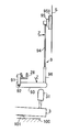
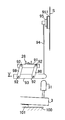
- 1 and 2 are side views for explaining one embodiment of the present invention. 1, 2, 3 and 4, the left side is the performer side on the front side of the upright piano, and the right side is the back side.
- the damper device 9 of the upright piano includes a damper lever 93, a damper wire 94 fixed to the rear end thereof, and a damper head 95 installed at the upper end of the damper wire 94.
- the damper lever 93 is pivotally supported by the damper flange 91 by a pivot pin 92.
- the damper flange 91 is fixed to a damper rail 28 fixed to a bracket (not shown) as a fixed portion installed on the shelf board 100 constituting the upright piano body.
- the damper device 9 shows a state in which the damper head 95 is in contact with the string S stretched in the vertical direction when the keyboard 3 is not pressed. At that time, a large number of keyboards 3 are arranged in parallel, and each keyboard 3 is placed on the ridge 101 placed on the shelf board 100 so that its approximate center is placed, and the keyboard 3 can swing freely like a seesaw.
- a protrusion 31 is planted at the rear end of the keyboard 3. 1 and 2 show a key release state in which the keyboard 3 is not touched, the protruding portion 31 is separated from the damper lever 93, and the damper head 95 is in contact with the string S.
- the weights of the damper lever 93, the damper wire 94, and the damper head 95 as the damper device 9 are directions in which the damper head 95 is rotated in the string S direction with the pivot pin 92 as a fulcrum.
- a load is applied in the direction of the arrow Z that brings the damper head 95 into contact with the string S.
- the damper lever 93, the damper wire 94, and the damper head 95 can be partially or entirely made of a material that is heavier, such as metal, wood, or plastic.
- the damper device 9 is provided with a damper head 95 provided with a damper felt 951 at the tip thereof by planting a damper wire 94 at a rear end portion of the damper lever 93 through a standing portion 96. It can also be configured.
- the damper device can also be configured such that the damper lever 93 is movable in the lateral direction.
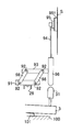
- the structure shown in FIG. 4 is fixed to a damper flange 91 on a stationary damper rail 28 fixed to a bracket or the like, and the upper ends of two arms 98 and 98 are rotated by a pivot pin 92 at an appropriate interval from the damper flange 91.
- the damper lever 93 is pivotally supported at the lower ends of the arms 98, 98. With this configuration, the damper lever 93 can be moved in the horizontal and horizontal directions.
- a damper wire 94 is planted at the rear end portion of the damper lever 93, and a damper head 95 is integrally formed at the upper end thereof.
- a protruding portion 31 provided at the rear end portion of the keyboard 3 is opposed to a lower portion of the rear end portion of the damper lever 93.
- the damper lever 93 is loaded with the weights of the arms 98 and 98, the damper wire 94, and the damper head 95 in the opposite arrow V direction through the arms 98 and 98 in addition to its own weight, and the damper head 95 and the damper felt 951.
- the string S is pressed to stop the sound generation.
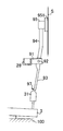
- FIG. 5 is substantially the same as the configuration of FIG. 4 except that the damper lever 93 is supported by the upper parts of the arms 98 and 98.
- a standing portion 96 is provided at the rear end portion of the damper lever 93, and the standing portion 96 is pushed up at the protruding portion 31, but the standing portion 96 is not provided (as shown in FIG. 4).
- the damper lever 93 may be directly pushed up at the upper portion 31.
- a damper head 95 is provided at the upper end of the damper lever 93 via a damper wire 94, and an inclined portion 97 is formed at the lower part of the damper lever 93.
- the damper lever 93 which is installed opposite the protruding upper portion 31, may be pivotally supported by a pivot pin 92 on a damper flange 91 provided on the damper rail 28.
- the damper wire 94 may be thick, or the configuration portion may be formed of metal, hard wood, heavy synthetic resin, etc., excluding the damper felt 951 of the damper head 95.
- X indicates an action.
- This action X indicates one action X corresponding to one keyboard 3, and is installed corresponding to each of the keyboards 3 arranged in parallel, and corresponds to the strings S that are stretched vertically in the rear part. To do.
- Each action X is fixedly installed at each position described below on a Whippen rail 22 installed between brackets (not shown) installed on the shelf board 100 of the upright piano.
- hammers 1, 1,... are installed in parallel on hammer shank rails 21 installed between the brackets on both sides of the piano, and actions X, X,. It is installed in parallel on the pen rail 22.
- the action X is installed corresponding to the keyboard 3 for each keyboard 3, and is composed of a capstan 4 planted on the keyboard 3, a whippen 5 pushed up by the capstan 4, and the whippen 5
- the repetition lever 6 and the jack 7 are provided.
- the whippen 5 is pivotally supported by a whippen frenzy 51 provided on the whippen rail 22 by a pin 52 at a front portion thereof.
- a heel 53 formed at the center bottom of the wippen 5 is provided with a projected upper portion 54 and faces the capstan 4.
- the central portion of the repetition lever 6 is pivotally supported by a pin 57.
- the jack 7 is pivotally supported by a pin 58 at the rear end of the wippen 5.
- the jack 7 is formed in a substantially L shape, its corner is pivotally supported by the wippen 5 by the pin 58, a contact portion 71 is formed at the lower end, and is opposed to the regulating button 23 provided on the regulating rail 2, A protruding portion 72 formed at the upper end is freely inserted into a guide hole 62 provided in the repetition lever 6.
- the repetition lever 6 provided in the repetition flange 55 of the whippen 5 so as to be rotatable by a pin 57 is threaded with a lever screw 63 at its front end so as to be movable up and down, and a lever button 64 is provided at the lower end thereof. As a contact.
- the rear end of the repetition lever 6 is formed with a slanted portion 65 at the top, and a lever skin 66 is provided.
- the inclined portion 65 of the repetition lever 6 is installed corresponding to the repetition screw 25 provided at the lower part of the hammer shank flange 24 provided on the hammer shank rail 21.
- reference numeral 1 denotes a hammer 1 which includes a hammer shank 11 and a hammer head 12.
- the hammer shank 11 includes a horizontal shank 11A and a vertical shank 11B.
- the vertical shank 11B is formed by being planted vertically with respect to the horizontal shank 11A.
- the horizontal shank 11A has a pivotal support hole 11a at one end and a catcher 14 at the other end.
- the vertical shank 11B is installed in a substantially vertical direction on the horizontal shank 11A at an appropriate distance from one end of the horizontal shank 11A or the pivot hole 11a.
- the shank roller 13 is installed below the horizontal shank 11A at a position corresponding to a protrusion 72 described later.
- the position of the shank roller 13 may be the same position as the position of the shank roller provided on the hammer shank in the grand piano. Further, the configuration of the shank roller 13 can be the same as the shape and configuration normally used in a grand piano.
- a reinforcing portion between the horizontal shank 11A and the vertical shank 11B.
- a housing 11C constructed between the horizontal shank 11A and the vertical shank 11B can be used.
- the reinforcing portion is not limited to the housing, and may be in a tubular shape, a plate shape, or the like.
- These horizontal shank 11A and vertical shank 11B can be made of an appropriate material such as a metal such as aluminum or iron, various plastics such as ABS, or various woods.
- the horizontal shank 11A and the vertical shank 11B can be formed of a constituent material having a desired shape such as a rod, a tube, or a flat plate.
- the configuration of the hammer shank 11 is such that the vertical shank 11B is planted with respect to the horizontal shank 11A provided with the shank roller 13 at the bottom, and the hammer head 12 on the vertical shank 11B is orthogonal to the string S stretched vertically.
- the purpose is to strike a string.
- the other action X configuration of the hammer 1 can use the action of a conventionally known grand piano with some exceptions. These actions are described in detail in Japanese Patent Application Laid-Open No. 2009-237138, Japanese Patent Application Laid-Open No. 2011-158757, and the like.
- the action X is the same as that used in the grand piano.
- the action X is not limited to this, and the bat is pushed up by a jack provided in a conventionally known whippen and planted on the bat.
- a jack provided in a conventionally known whippen and planted on the bat.
- the damper head 95 installed at the tip of the damper wire 94 provided at the end of the damper lever 93 has the damper lever 93 with the pivot pin 92 as a fulcrum by the weight of the damper lever 93 and the damper wire 94 that supports the damper head 95.
- the weight is applied to the rear side, and the damper head 95 is rotated and stopped by the string S.
- the keyboard 3 is not pushed up even in the action X, and the capstan 4 does not push the whippen 5.
- the repetition lever 6 pivoted on the wippen 5 and the hammer 1 placed thereon are also stopped, and the hammer head 12 on the vertical shank 11B of the hammer 1 is also kept at a predetermined distance from the string S. .
- the rear portion of the keyboard 3 is rotated and raised via the hook 101.
- the capstan 4 rises and pushes the whippen 5 through the upper part 31.
- the wippen 5 rotates about the pin 52 as a fulcrum, and at the same time, the repetition lever 6 and the jack 7 pivotally supported by the wippen 5 are rotated.
- the repetition lever 6 pushes up the shank roller 13, and further, the protrusion 72 of the jack 7 pushes up the shank roller 13 by the rotation of the wippen 5.
- the protrusion 72 protrudes upward from the guide hole 62 of the repetition lever 6 and pushes up the shank roller 13, and the hammer 1 rotates about the pin 26 in the Y direction in FIG.
- the hammer 1 is inertia and rotates in a direction away from the action X and the keyboard 3, and the hammer head 12 hits the string S to generate a sound.
- the protrusion 31 provided at the rear end of the keyboard 3 rises, and the rear end of the damper lever 93 pivotally supported by the damper flange 91 is pushed up.
- the damper lever 93 is pivoted. It rotates in the counter-arrow Z direction about 92.
- the damper head 95 is rotated in the direction of the opposite arrow Z through the damper wire 94 to leave the string S, free the string S, and the musical sound before the hammer head 12 strikes the string S. It is assumed that it can occur.
- the catcher 14 provided on the side shank 11A hits the check 43, and the hammer shank 11 stops.
- the repetition lever 6 is pushed back by the force of the repetition spring 8, and as a result, the protruding portion 72 of the jack 7 returns below the shank roller 13. Further, at the end of the key pressing, the next key can be hit without returning the entire keyboard 3, and the protruding portion 72 of the jack 7 can push up the shank roller 13 by the next key hit.
- the hammer operating mechanism and the damper operating mechanism are made independent by changing the configuration of performing the stringing operation by the hammer and the damper operation via the whippen in the conventional keystroke. Since the hammer operation is performed through the wippen by the keystroke and the damper operation is directly operated by the keystroke, the hammer can be moved in the left-right direction in the same manner as the grand piano operation. As a result, the hammer can be made an upright piano simply by changing the configuration of the hammer portion via the wippen by the operation of the keystroke, and it is possible to provide an upright piano that is extremely mass-productive and economically excellent.
Landscapes
- Physics & Mathematics (AREA)
- Engineering & Computer Science (AREA)
- Acoustics & Sound (AREA)
- Multimedia (AREA)
- Electrophonic Musical Instruments (AREA)
Priority Applications (1)
| Application Number | Priority Date | Filing Date | Title |
|---|---|---|---|
| PCT/JP2012/050985 WO2013108382A1 (fr) | 2012-01-18 | 2012-01-18 | Dispositif amortisseur pour piano droit |
Applications Claiming Priority (1)
| Application Number | Priority Date | Filing Date | Title |
|---|---|---|---|
| PCT/JP2012/050985 WO2013108382A1 (fr) | 2012-01-18 | 2012-01-18 | Dispositif amortisseur pour piano droit |
Publications (1)
| Publication Number | Publication Date |
|---|---|
| WO2013108382A1 true WO2013108382A1 (fr) | 2013-07-25 |
Family
ID=48798830
Family Applications (1)
| Application Number | Title | Priority Date | Filing Date |
|---|---|---|---|
| PCT/JP2012/050985 Ceased WO2013108382A1 (fr) | 2012-01-18 | 2012-01-18 | Dispositif amortisseur pour piano droit |
Country Status (1)
| Country | Link |
|---|---|
| WO (1) | WO2013108382A1 (fr) |
Cited By (2)
| Publication number | Priority date | Publication date | Assignee | Title |
|---|---|---|---|---|
| CN110070843A (zh) * | 2019-05-07 | 2019-07-30 | 南阳理工学院 | 一种具有同时半击琴键设计性能的三角钢琴击弦机 |
| CN116386569A (zh) * | 2023-05-09 | 2023-07-04 | 海伦钢琴股份有限公司 | 一种可以快速复奏的立式钢琴击弦机 |
Citations (5)
| Publication number | Priority date | Publication date | Assignee | Title |
|---|---|---|---|---|
| JPS6366595A (ja) * | 1986-09-09 | 1988-03-25 | 田中通商株式会社 | アツプライトピアノ用アクシヨン機構 |
| US4879939A (en) * | 1986-09-04 | 1989-11-14 | Wall Paul G | Action for upright piano |
| US5123321A (en) * | 1987-12-01 | 1992-06-23 | Caught Anthony G | Piano |
| JP2008090168A (ja) * | 2006-10-04 | 2008-04-17 | Kawai Musical Instr Mfg Co Ltd | アップライトピアノのダンパー装置 |
| JP2008513812A (ja) * | 2004-09-14 | 2008-05-01 | バフンノ,パスカーレ | アップライトピアノ用レペティション・アクション機構 |
-
2012
- 2012-01-18 WO PCT/JP2012/050985 patent/WO2013108382A1/fr not_active Ceased
Patent Citations (5)
| Publication number | Priority date | Publication date | Assignee | Title |
|---|---|---|---|---|
| US4879939A (en) * | 1986-09-04 | 1989-11-14 | Wall Paul G | Action for upright piano |
| JPS6366595A (ja) * | 1986-09-09 | 1988-03-25 | 田中通商株式会社 | アツプライトピアノ用アクシヨン機構 |
| US5123321A (en) * | 1987-12-01 | 1992-06-23 | Caught Anthony G | Piano |
| JP2008513812A (ja) * | 2004-09-14 | 2008-05-01 | バフンノ,パスカーレ | アップライトピアノ用レペティション・アクション機構 |
| JP2008090168A (ja) * | 2006-10-04 | 2008-04-17 | Kawai Musical Instr Mfg Co Ltd | アップライトピアノのダンパー装置 |
Cited By (3)
| Publication number | Priority date | Publication date | Assignee | Title |
|---|---|---|---|---|
| CN110070843A (zh) * | 2019-05-07 | 2019-07-30 | 南阳理工学院 | 一种具有同时半击琴键设计性能的三角钢琴击弦机 |
| CN110070843B (zh) * | 2019-05-07 | 2022-11-08 | 南阳理工学院 | 一种具有同时半击琴键设计性能的三角钢琴击弦机 |
| CN116386569A (zh) * | 2023-05-09 | 2023-07-04 | 海伦钢琴股份有限公司 | 一种可以快速复奏的立式钢琴击弦机 |
Similar Documents
| Publication | Publication Date | Title |
|---|---|---|
| JP5298534B2 (ja) | アクション機構 | |
| JP5412859B2 (ja) | アップライト型アクション及び鍵盤楽器 | |
| US12542118B2 (en) | Keyboard device for keyboard instrument | |
| JPH07219522A (ja) | 鍵盤楽器 | |
| JP5659525B2 (ja) | 鍵盤装置 | |
| JP5488985B2 (ja) | アップライトピアノ型アクション | |
| KR100611605B1 (ko) | 업라이트형 건반악기 | |
| EP2461319B1 (fr) | Action de piano droit | |
| US10134371B2 (en) | Stroke adjustment device for keyboard instrument | |
| WO2013108382A1 (fr) | Dispositif amortisseur pour piano droit | |
| JP2011203296A (ja) | 鍵盤装置 | |
| JP2015014661A (ja) | アップライトピアノ用ハンマー及びそれを用いた打弦機構と該打弦機構を搭載したアップライトピアノ | |
| JP6098621B2 (ja) | 鍵盤楽器のアクション機構 | |
| JP5659526B2 (ja) | 鍵盤装置 | |
| JP5560817B2 (ja) | ピアノ型アクション | |
| JPH11282471A (ja) | 鍵盤楽器 | |
| JP2006243294A (ja) | アップライトピアノのハンマー | |
| JP2007108661A (ja) | アップライトピアノのアクション | |
| WO2013094060A1 (fr) | Marteau pour piano droit et mécanisme de frappe de corde utilisant celui-ci | |
| JP5757494B1 (ja) | アップライトピアノのアクション機構 | |
| JP6725777B1 (ja) | ホイール付きバットを用いたアップライト型ピアノアクション機構 | |
| JP2004252252A (ja) | グランド型ピアノのアクション | |
| JP3856032B2 (ja) | 鍵盤楽器 | |
| JP2003263152A (ja) | アップライトピアノのアクション機構 | |
| JPH07234668A (ja) | 竪型鍵盤楽器 |
Legal Events
| Date | Code | Title | Description |
|---|---|---|---|
| 121 | Ep: the epo has been informed by wipo that ep was designated in this application |
Ref document number: 12866233 Country of ref document: EP Kind code of ref document: A1 |
|
| NENP | Non-entry into the national phase |
Ref country code: DE |
|
| 32PN | Ep: public notification in the ep bulletin as address of the adressee cannot be established |
Free format text: NOTING OF LOSS OF RIGHTS PURSUANT TO RULE 112(1) EPC (EPO FORM 1205A DATED 31/10/2014) |
|
| NENP | Non-entry into the national phase |
Ref country code: JP |
|
| 122 | Ep: pct application non-entry in european phase |
Ref document number: 12866233 Country of ref document: EP Kind code of ref document: A1 |