WO2013108455A1 - 内燃機関の制御装置 - Google Patents
内燃機関の制御装置 Download PDFInfo
- Publication number
- WO2013108455A1 WO2013108455A1 PCT/JP2012/077074 JP2012077074W WO2013108455A1 WO 2013108455 A1 WO2013108455 A1 WO 2013108455A1 JP 2012077074 W JP2012077074 W JP 2012077074W WO 2013108455 A1 WO2013108455 A1 WO 2013108455A1
- Authority
- WO
- WIPO (PCT)
- Prior art keywords
- amount
- intake air
- air amount
- intake
- engine
- Prior art date
- Legal status (The legal status is an assumption and is not a legal conclusion. Google has not performed a legal analysis and makes no representation as to the accuracy of the status listed.)
- Ceased
Links
Images


Classifications
-
- F—MECHANICAL ENGINEERING; LIGHTING; HEATING; WEAPONS; BLASTING
- F02—COMBUSTION ENGINES; HOT-GAS OR COMBUSTION-PRODUCT ENGINE PLANTS
- F02M—SUPPLYING COMBUSTION ENGINES IN GENERAL WITH COMBUSTIBLE MIXTURES OR CONSTITUENTS THEREOF
- F02M25/00—Engine-pertinent apparatus for adding non-fuel substances or small quantities of secondary fuel to combustion-air, main fuel or fuel-air mixture
- F02M25/08—Engine-pertinent apparatus for adding non-fuel substances or small quantities of secondary fuel to combustion-air, main fuel or fuel-air mixture adding fuel vapours drawn from engine fuel reservoir
-
- F—MECHANICAL ENGINEERING; LIGHTING; HEATING; WEAPONS; BLASTING
- F02—COMBUSTION ENGINES; HOT-GAS OR COMBUSTION-PRODUCT ENGINE PLANTS
- F02D—CONTROLLING COMBUSTION ENGINES
- F02D41/00—Electrical control of supply of combustible mixture or its constituents
- F02D41/0025—Controlling engines characterised by use of non-liquid fuels, pluralities of fuels, or non-fuel substances added to the combustible mixtures
- F02D41/0047—Controlling exhaust gas recirculation [EGR]
- F02D41/005—Controlling exhaust gas recirculation [EGR] according to engine operating conditions
- F02D41/0052—Feedback control of engine parameters, e.g. for control of air/fuel ratio or intake air amount
-
- F—MECHANICAL ENGINEERING; LIGHTING; HEATING; WEAPONS; BLASTING
- F02—COMBUSTION ENGINES; HOT-GAS OR COMBUSTION-PRODUCT ENGINE PLANTS
- F02D—CONTROLLING COMBUSTION ENGINES
- F02D41/00—Electrical control of supply of combustible mixture or its constituents
- F02D41/0025—Controlling engines characterised by use of non-liquid fuels, pluralities of fuels, or non-fuel substances added to the combustible mixtures
- F02D41/0047—Controlling exhaust gas recirculation [EGR]
- F02D41/006—Controlling exhaust gas recirculation [EGR] using internal EGR
- F02D41/0062—Estimating, calculating or determining the internal EGR rate, amount or flow
-
- F—MECHANICAL ENGINEERING; LIGHTING; HEATING; WEAPONS; BLASTING
- F02—COMBUSTION ENGINES; HOT-GAS OR COMBUSTION-PRODUCT ENGINE PLANTS
- F02D—CONTROLLING COMBUSTION ENGINES
- F02D41/00—Electrical control of supply of combustible mixture or its constituents
- F02D41/0025—Controlling engines characterised by use of non-liquid fuels, pluralities of fuels, or non-fuel substances added to the combustible mixtures
- F02D41/0047—Controlling exhaust gas recirculation [EGR]
- F02D41/0065—Specific aspects of external EGR control
- F02D41/0072—Estimating, calculating or determining the EGR rate, amount or flow
-
- F—MECHANICAL ENGINEERING; LIGHTING; HEATING; WEAPONS; BLASTING
- F02—COMBUSTION ENGINES; HOT-GAS OR COMBUSTION-PRODUCT ENGINE PLANTS
- F02D—CONTROLLING COMBUSTION ENGINES
- F02D41/00—Electrical control of supply of combustible mixture or its constituents
- F02D41/24—Electrical control of supply of combustible mixture or its constituents characterised by the use of digital means
- F02D41/2406—Electrical control of supply of combustible mixture or its constituents characterised by the use of digital means using essentially read only memories
- F02D41/2425—Particular ways of programming the data
- F02D41/2429—Methods of calibrating or learning
- F02D41/2441—Methods of calibrating or learning characterised by the learning conditions
- F02D41/2445—Methods of calibrating or learning characterised by the learning conditions characterised by a plurality of learning conditions or ranges
-
- F—MECHANICAL ENGINEERING; LIGHTING; HEATING; WEAPONS; BLASTING
- F02—COMBUSTION ENGINES; HOT-GAS OR COMBUSTION-PRODUCT ENGINE PLANTS
- F02D—CONTROLLING COMBUSTION ENGINES
- F02D41/00—Electrical control of supply of combustible mixture or its constituents
- F02D41/24—Electrical control of supply of combustible mixture or its constituents characterised by the use of digital means
- F02D41/2406—Electrical control of supply of combustible mixture or its constituents characterised by the use of digital means using essentially read only memories
- F02D41/2425—Particular ways of programming the data
- F02D41/2429—Methods of calibrating or learning
- F02D41/2451—Methods of calibrating or learning characterised by what is learned or calibrated
- F02D41/2454—Learning of the air-fuel ratio control
-
- F—MECHANICAL ENGINEERING; LIGHTING; HEATING; WEAPONS; BLASTING
- F02—COMBUSTION ENGINES; HOT-GAS OR COMBUSTION-PRODUCT ENGINE PLANTS
- F02P—IGNITION, OTHER THAN COMPRESSION IGNITION, FOR INTERNAL-COMBUSTION ENGINES; TESTING OF IGNITION TIMING IN COMPRESSION-IGNITION ENGINES
- F02P5/00—Advancing or retarding ignition; Control therefor
- F02P5/04—Advancing or retarding ignition; Control therefor automatically, as a function of the working conditions of the engine or vehicle or of the atmospheric conditions
- F02P5/145—Advancing or retarding ignition; Control therefor automatically, as a function of the working conditions of the engine or vehicle or of the atmospheric conditions using electrical means
- F02P5/15—Digital data processing
- F02P5/1502—Digital data processing using one central computing unit
- F02P5/1516—Digital data processing using one central computing unit with means relating to exhaust gas recirculation, e.g. turbo
-
- F—MECHANICAL ENGINEERING; LIGHTING; HEATING; WEAPONS; BLASTING
- F02—COMBUSTION ENGINES; HOT-GAS OR COMBUSTION-PRODUCT ENGINE PLANTS
- F02P—IGNITION, OTHER THAN COMPRESSION IGNITION, FOR INTERNAL-COMBUSTION ENGINES; TESTING OF IGNITION TIMING IN COMPRESSION-IGNITION ENGINES
- F02P5/00—Advancing or retarding ignition; Control therefor
- F02P5/04—Advancing or retarding ignition; Control therefor automatically, as a function of the working conditions of the engine or vehicle or of the atmospheric conditions
- F02P5/145—Advancing or retarding ignition; Control therefor automatically, as a function of the working conditions of the engine or vehicle or of the atmospheric conditions using electrical means
- F02P5/15—Digital data processing
- F02P5/152—Digital data processing dependent on pinking
-
- F—MECHANICAL ENGINEERING; LIGHTING; HEATING; WEAPONS; BLASTING
- F02—COMBUSTION ENGINES; HOT-GAS OR COMBUSTION-PRODUCT ENGINE PLANTS
- F02D—CONTROLLING COMBUSTION ENGINES
- F02D41/00—Electrical control of supply of combustible mixture or its constituents
- F02D41/0002—Controlling intake air
- F02D2041/001—Controlling intake air for engines with variable valve actuation
-
- F—MECHANICAL ENGINEERING; LIGHTING; HEATING; WEAPONS; BLASTING
- F02—COMBUSTION ENGINES; HOT-GAS OR COMBUSTION-PRODUCT ENGINE PLANTS
- F02D—CONTROLLING COMBUSTION ENGINES
- F02D2200/00—Input parameters for engine control
- F02D2200/02—Input parameters for engine control the parameters being related to the engine
- F02D2200/04—Engine intake system parameters
- F02D2200/0402—Engine intake system parameters the parameter being determined by using a model of the engine intake or its components
-
- F—MECHANICAL ENGINEERING; LIGHTING; HEATING; WEAPONS; BLASTING
- F02—COMBUSTION ENGINES; HOT-GAS OR COMBUSTION-PRODUCT ENGINE PLANTS
- F02D—CONTROLLING COMBUSTION ENGINES
- F02D2200/00—Input parameters for engine control
- F02D2200/02—Input parameters for engine control the parameters being related to the engine
- F02D2200/04—Engine intake system parameters
- F02D2200/0414—Air temperature
-
- F—MECHANICAL ENGINEERING; LIGHTING; HEATING; WEAPONS; BLASTING
- F02—COMBUSTION ENGINES; HOT-GAS OR COMBUSTION-PRODUCT ENGINE PLANTS
- F02D—CONTROLLING COMBUSTION ENGINES
- F02D41/00—Electrical control of supply of combustible mixture or its constituents
- F02D41/0025—Controlling engines characterised by use of non-liquid fuels, pluralities of fuels, or non-fuel substances added to the combustible mixtures
- F02D41/003—Adding fuel vapours, e.g. drawn from engine fuel reservoir
- F02D41/0042—Controlling the combustible mixture as a function of the canister purging, e.g. control of injected fuel to compensate for deviation of air fuel ratio when purging
-
- F—MECHANICAL ENGINEERING; LIGHTING; HEATING; WEAPONS; BLASTING
- F02—COMBUSTION ENGINES; HOT-GAS OR COMBUSTION-PRODUCT ENGINE PLANTS
- F02D—CONTROLLING COMBUSTION ENGINES
- F02D41/00—Electrical control of supply of combustible mixture or its constituents
- F02D41/0025—Controlling engines characterised by use of non-liquid fuels, pluralities of fuels, or non-fuel substances added to the combustible mixtures
- F02D41/003—Adding fuel vapours, e.g. drawn from engine fuel reservoir
- F02D41/0045—Estimating, calculating or determining the purging rate, amount, flow or concentration
-
- F—MECHANICAL ENGINEERING; LIGHTING; HEATING; WEAPONS; BLASTING
- F02—COMBUSTION ENGINES; HOT-GAS OR COMBUSTION-PRODUCT ENGINE PLANTS
- F02D—CONTROLLING COMBUSTION ENGINES
- F02D41/00—Electrical control of supply of combustible mixture or its constituents
- F02D41/02—Circuit arrangements for generating control signals
- F02D41/18—Circuit arrangements for generating control signals by measuring intake air flow
-
- F—MECHANICAL ENGINEERING; LIGHTING; HEATING; WEAPONS; BLASTING
- F02—COMBUSTION ENGINES; HOT-GAS OR COMBUSTION-PRODUCT ENGINE PLANTS
- F02M—SUPPLYING COMBUSTION ENGINES IN GENERAL WITH COMBUSTIBLE MIXTURES OR CONSTITUENTS THEREOF
- F02M26/00—Engine-pertinent apparatus for adding exhaust gases to combustion-air, main fuel or fuel-air mixture, e.g. by exhaust gas recirculation [EGR] systems
-
- Y—GENERAL TAGGING OF NEW TECHNOLOGICAL DEVELOPMENTS; GENERAL TAGGING OF CROSS-SECTIONAL TECHNOLOGIES SPANNING OVER SEVERAL SECTIONS OF THE IPC; TECHNICAL SUBJECTS COVERED BY FORMER USPC CROSS-REFERENCE ART COLLECTIONS [XRACs] AND DIGESTS
- Y02—TECHNOLOGIES OR APPLICATIONS FOR MITIGATION OR ADAPTATION AGAINST CLIMATE CHANGE
- Y02T—CLIMATE CHANGE MITIGATION TECHNOLOGIES RELATED TO TRANSPORTATION
- Y02T10/00—Road transport of goods or passengers
- Y02T10/10—Internal combustion engine [ICE] based vehicles
- Y02T10/40—Engine management systems
Definitions
- the present invention relates to a control device for an internal combustion engine, and more particularly to a control device for an internal combustion engine that performs control based on an exhaust gas recirculation rate that indicates a ratio of exhaust gas (combustion gas) contained in gas sucked into a combustion chamber of the engine.
- Patent Document 1 discloses a method of using an intake air amount sensor for detecting an intake air amount of an engine for calculating an exhaust gas recirculation rate.
- the detected intake air amount may deviate from the actual intake air amount due to variations in the characteristics of the intake air amount sensor and other factors. If there is such a detection deviation in the method of Patent Document 1, the calculation accuracy of the exhaust gas recirculation rate is increased. descend.
- Patent Document 2 discloses an air-fuel ratio control device that reduces the influence of detection deviation of an intake air amount sensor.
- the air-fuel ratio feedback control amount is calculated according to the air-fuel ratio (oxygen concentration) detected in the engine exhaust system, and air-fuel ratio feedback control is performed using the air-fuel ratio feedback control amount.
- the upper limit value of the intake air amount sensor detection value is changed based on the air-fuel ratio feedback control amount. This prevents the air-fuel ratio control accuracy from deteriorating, particularly due to the effect of blowback due to intake air pulsation.
- the intake air amount sensor fails, or if there is a disconnection of the exhaust gas recirculation passage, evaporative fuel passage, etc. connected to the engine intake system, even if the engine is in an operating state other than a high-load operating state,
- the intake air amount detected by the air amount sensor greatly deviates from the actual intake air amount, and the exhaust gas recirculation rate calculation accuracy decreases. Therefore, the control accuracy of fuel supply control and ignition timing control corresponding to the exhaust gas recirculation rate calculated using the detected intake air amount is deteriorated.
- the air-fuel ratio feedback control is performed, so that the actual air-fuel ratio can be maintained at a desired value in the steady operation state, but the control accuracy is deteriorated in the transient operation state.
- the ignition timing control an intake air amount detection error causes an increase in knocking or misfire even in a steady operating state.
- Patent Document 2 there is room for improvement because an abnormal state such as the above-described pipe disconnection is not taken into consideration.
- An object of the present invention is to provide a control device for an internal combustion engine that can avoid a situation in which the control accuracy of the used control is greatly deteriorated.
- the present invention is directed to a throttle valve (3) provided in an intake passage (2) of an internal combustion engine (1), and evaporated fuel and air generated in a fuel tank that supplies fuel to the engine.
- a control device for an internal combustion engine comprising: an evaporative fuel passage (25) for supplying an evaporative fuel mixture as an air-fuel mixture to the intake passage (2).
- This control device is in a state in which the rotational speed detecting means for detecting the rotational speed (NE) of the engine, the intake pressure detecting means for detecting the intake pressure (PBA) of the engine, and the throttle valve (3) are fully opened.
- a fully open intake air amount calculation means for calculating a fully open intake air amount (GAWOT) corresponding to the engine speed according to the engine speed (NE), and a state in which the exhaust of the engine is not recirculated to the combustion chamber
- a theoretical intake air amount calculating means for calculating a theoretical intake air amount (GATH) according to the fully open intake air amount (GAWOT) and the intake pressure (PBA), and detecting an intake air amount (GACYLTMP) of the engine Intake air amount detection means, air-fuel ratio detection means for detecting the air-fuel ratio (KACT) in the exhaust passage (21) of the engine, and air-fuel ratio correction amount (KA) according to the detected air-fuel ratio (KACT) ),
- An learned value calculating means for calculating a learning value (KREFX) of the air / fuel ratio correction amount (KAF), the intake pressure (PBA) and the engine speed (NE),
- a reference intake air amount calculation means for calculating a reference intake air amount (GACYLREF) using the air
- Vaporized fuel for calculating the amount of fuel vapor mixture (GPGC) supplied to the intake passage (2) via the processing means and the evaporated fuel passage (25)
- Aspiration amount calculation means and intake gas amount calculation means for calculating an intake gas amount (GINGASCYL) by correcting the intake air amount (GAIRCYL) after the limit processing using the evaporated fuel mixture amount (GPGC)
- an exhaust gas recirculation rate calculating means for calculating an exhaust gas recirculation rate (REGRT) using the theoretical intake air amount (GATH) and the intake gas amount (GINGASCYL), and using the exhaust gas recirculation rate (REGRT), the engine It is characterized by controlling.
- the fully-open intake air amount that is the intake air amount corresponding to the state where the throttle valve is fully opened is calculated according to the engine speed, and the theoretical intake air amount corresponding to the state where there is no exhaust gas recirculation is obtained. It is calculated according to the fully open intake air amount and the intake pressure. Further, the amount of the evaporated fuel mixture supplied to the intake passage via the evaporated fuel passage is calculated, the amount of intake gas is calculated by correcting the amount of intake air using the amount of the evaporated fuel mixture, and the calculated amount of intake gas And the theoretical intake air amount are used to calculate the exhaust gas recirculation rate, and engine control is performed using the calculated exhaust gas recirculation rate.
- an air-fuel ratio correction amount is calculated according to the detected air-fuel ratio, and a learning value of the air-fuel ratio correction amount is calculated, and the intake pressure, the engine speed, the air-fuel ratio correction amount, and the learning value are used.
- a reference intake air amount is calculated, a lower limit value of the intake air amount is calculated according to the reference intake air amount, and limit processing is performed to limit the detected intake air amount to a range equal to or greater than the lower limit value. Therefore, an accurate exhaust gas recirculation rate that takes into account the fuel vapor mixture can be obtained by a relatively simple calculation, and the engine control accuracy can be improved.
- the lower limit value of the detected intake air amount is set using the air-fuel ratio correction amount reflecting the actual air-fuel ratio of the air-fuel mixture combusted in the engine and the learned value together with the intake pressure and the engine speed, for example, Appropriate limit processing was performed to limit the detected intake air amount to the range above the set lower limit when the intake air amount detection means failed or the evaporative fuel passage was disconnected. It is possible to avoid a situation in which the accuracy of engine control is greatly deteriorated.
- the engine further includes optimum ignition timing calculation means for calculating an optimum ignition timing (IGMBT) that maximizes the output of the engine according to the exhaust gas recirculation rate (REGRT), and using the optimum ignition timing (IGMBT), the engine It is desirable to control the ignition timing.
- IGMBT optimum ignition timing
- the optimal ignition timing is calculated according to the exhaust gas recirculation rate, and the ignition timing control is performed using the calculated optimal ignition timing. Since it has been confirmed that the relationship between the exhaust gas recirculation rate and the optimal ignition timing is not affected by the operating phase of the intake valve or the presence or absence of external exhaust gas recirculation, by setting the optimal ignition timing according to the exhaust gas recirculation rate The optimum ignition timing suitable for the engine operating state can be easily calculated.
- a knock detection means (14) for detecting knocking of the engine, and a delay for calculating a retard correction amount (DIGKCS) of the ignition timing so as to increase as the frequency of detection of knock by the knock detection means (14) increases.
- the angle correction amount calculating means and the retardation correction amount (DIGKCS) reach the retardation limit value (DIGKMAX)
- the intake air amount (GAIRCYL) after the limit processing is set to the reference intake air amount (GACYLREF). It is desirable to further include a fail-safe processing means for replacing, and to perform ignition timing control of the engine using the retardation correction amount (DIGKCS).
- the ignition timing retardation correction amount is calculated so as to increase as the knocking detection frequency increases, and the ignition timing control is performed using the retardation correction amount.
- fail-safe processing is performed to replace the intake air amount after the limit processing with the reference intake air amount, so the detected intake air amount is larger than the actual intake air amount. It is possible to reliably prevent the occurrence of knocking in the shifted state.
- the engine includes an exhaust gas recirculation passage (22) for recirculating exhaust gas from the exhaust passage (21) to the intake air passage (2), and flows into the intake air passage (2) through the exhaust gas recirculation passage (22).
- Estimated recirculation gas amount calculation means for calculating an estimated recirculation gas amount (GEGREXE) that is an estimated value of the gas amount to be performed, and an air-fuel ratio obtained by dividing the air-fuel ratio correction amount (KAF) by the learning value (KREFX)
- the exhaust gas recirculation passage (22) is abnormal when the determination parameter (KAFDET) is within a predetermined range (RABNL) set according to the detected intake air amount (GACYLTMP) and the estimated recirculation gas amount (GEGREXE).
- An abnormality determining means for determining that there is an exhaust gas and the reference intake air amount calculating means includes a target value (REGR) of an external exhaust gas recirculation rate by the exhaust gas recirculation passage (22) XCMD) is equal to or greater than a predetermined value (REGREXTH), the engine is in a predetermined high-load operation state, and the exhaust gas recirculation passage (22) is determined to be abnormal by the abnormality determining means, and the retardation correction is performed.
- the amount (DIGKCS) reaches the retardation limit value (DIGKMAX)
- GACYLREF GACYLREF
- the fail-safe processing means preferably replaces the intake air amount after the limit processing (GAIRCYL) with the corrected reference intake air amount (GACYLREF).
- the estimated recirculation gas amount that is an estimated value of the gas amount flowing into the intake passage via the exhaust recirculation passage is calculated, and the air-fuel ratio determination parameter obtained by dividing the air-fuel ratio correction amount by the learning value
- the exhaust gas recirculation passage is abnormal when it is within a predetermined range set according to the detected intake air amount and the estimated recirculation gas amount.
- the target value of the external exhaust gas recirculation rate by the exhaust gas recirculation passage is greater than or equal to a predetermined value, the engine is in a predetermined high load operating state, the exhaust gas recirculation passage is abnormal, and the retard correction amount is the retard limit
- the reference intake air amount is corrected by multiplying the reference intake air amount by the air-fuel ratio determination parameter, and the fail intake is replaced with the corrected reference intake air amount after the limit process. Processing is performed.
- the reference intake air amount calculated according to the intake pressure greatly deviates from the actual intake air amount. Therefore, the reference intake air corrected by multiplying the air-fuel ratio determination parameter is used. By applying the amount, the actual intake air amount can be accurately approximated.
- an evaporative fuel concentration calculation means for calculating an evaporative fuel concentration (KAFEVACT) in the evaporative fuel mixture, and the evaporative fuel calculated according to the evaporative fuel mixture amount (GPGC) and the evaporative fuel concentration (KAFEVACT)
- Corrected intake air amount calculating means for correcting the intake air amount (GAIRCYL) using the fresh air amount (GPGACYL) in the air-fuel mixture and calculating the corrected intake air amount (GAIRCYLC), and the occurrence limit of knocking in the engine
- Knock limit ignition timing calculating means for calculating a corresponding knock limit ignition timing (IGKNOCK) according to the exhaust gas recirculation rate (REGRT) and the corrected intake air amount (GAIRCYLC), and further comprising the optimal ignition timing (IGMBT) or Using the ignition timing on the retard side of any of the knock limit ignition timing (IGKNOCK) It is desirable to carry out the fire timing control.
- the evaporated fuel concentration in the evaporated fuel mixture is calculated, and the amount of intake air is calculated using the amount of evaporated fuel mixture and the amount of fresh air in the evaporated fuel mixture calculated according to the evaporated fuel concentration.
- the corrected intake air amount is corrected and the knock limit ignition timing is calculated according to the exhaust gas recirculation rate and the corrected intake air amount. Since the knock limit ignition timing is highly correlated with the exhaust gas recirculation rate, by calculating the knock limit ignition timing according to the exhaust gas recirculation rate, ignition timing control that maximizes engine output within a range where knocking can be reliably avoided Can be performed with high accuracy.
- the amount of fresh air sucked into the cylinder is obtained by adding the amount of fresh air in the fuel vapor mixture to the amount of intake air. Therefore, by calculating the knock limit ignition timing according to the exhaust gas recirculation rate and the corrected intake air amount, the calculation accuracy of the knock limit ignition timing can be increased.
- FIG. 1 It is a figure which shows the structure of the internal combustion engine and its control apparatus concerning one Embodiment of this invention. It is a figure which shows schematic structure of the valve action characteristic variable apparatus shown in FIG. It is a figure which shows the change of the action
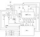
- FIG. 1 is a diagram showing a configuration of an internal combustion engine and its control device according to an embodiment of the present invention
- FIG. 2 is a diagram showing a configuration of a valve operating characteristic variable device.
- an internal combustion engine (hereinafter simply referred to as “engine”) 1 having four cylinders includes an intake valve and an exhaust valve, and a cam for driving them, and a crankshaft rotation angle of the cam for driving the intake valve.
- a valve operation characteristic variable device 40 having a valve operation characteristic variable mechanism 42 as a cam phase variable mechanism for continuously changing the operation phase with reference to. The operation phase of the cam that drives the intake valve is changed by the variable valve operation characteristic mechanism 42, and the operation phase of the intake valve is changed.
- a throttle valve 3 is disposed in the intake passage 2 of the engine 1.
- the throttle valve 3 is connected to a throttle valve opening sensor 4 for detecting the throttle valve opening TH, and the detection signal is supplied to an electronic control unit (hereinafter referred to as “ECU”) 5.
- An actuator 7 that drives the throttle valve 3 is connected to the throttle valve 3, and the operation of the actuator 7 is controlled by the ECU 5.
- An intake air flow rate sensor 13 that detects an intake air flow rate GAIR of the engine 1 is provided in the intake passage 2.
- a detection signal of the intake air flow rate sensor 13 is supplied to the ECU 5.
- the evaporative fuel passage 25 is connected to the intake passage 2 downstream of the throttle valve 3, and the evaporative fuel passage 25 is connected to a canister (not shown).
- the evaporative fuel passage 25 is provided with a purge control valve 26 for controlling the flow rate of a mixture of evaporative fuel and air (evaporated fuel mixture, hereinafter referred to as “purge gas”).
- purge gas evaporated fuel mixture
- the operation of the purge control valve 26 is controlled by the ECU 5.
- the canister stores evaporated fuel generated in a fuel tank that supplies fuel to the engine 1. When the purge control valve 26 is opened, purge gas from the canister passes through the evaporated fuel passage 25 and the intake passage. 2 is supplied.
- An exhaust gas recirculation passage 22 is provided between the exhaust passage 21 and the intake air passage 2, and the exhaust gas recirculation passage 22 is connected to the intake air passage 2 on the downstream side of the throttle valve 3.
- the exhaust gas recirculation passage 22 is provided with an exhaust gas recirculation control valve 23 for controlling the exhaust gas recirculation amount, and the operation of the exhaust gas recirculation control valve 23 is controlled by the ECU 5.
- An oxygen concentration sensor 24 (hereinafter referred to as “LAF sensor 24”) is attached to the exhaust passage 21, and this LAF sensor 24 supplies a detection signal substantially proportional to the oxygen concentration (air-fuel ratio) in the exhaust to the ECU 5. .
- the fuel injection valve 6 is provided for each cylinder between the engine 1 and the throttle valve 3 and slightly upstream of the intake valve (not shown) in the intake passage 2, and each injection valve is connected to a fuel pump (not shown). At the same time, it is electrically connected to the ECU 5 and the valve opening time of the fuel injection valve 6 is controlled by a signal from the ECU 5.
- the ignition plug 15 of each cylinder of the engine 1 is connected to the ECU 5, and the ECU 5 supplies an ignition signal to the ignition plug 15 to perform ignition timing control.
- An intake pressure sensor 8 for detecting the intake pressure PBA and an intake temperature sensor 9 for detecting the intake temperature TA are mounted downstream of the throttle valve 3.
- An engine cooling water temperature sensor 10 that detects the engine cooling water temperature TW is attached to the main body of the engine 1. Detection signals from these sensors are supplied to the ECU 5.
- the ECU 5 includes a crank angle position sensor 11 that detects a rotation angle of a crankshaft (not shown) of the engine 1 and a cam angle that detects a rotation angle of a camshaft to which a cam that drives an intake valve of the engine 1 is fixed.
- a position sensor 12 is connected, and signals corresponding to the rotation angle of the crankshaft and the rotation angle of the camshaft are supplied to the ECU 5.
- the crank angle position sensor 11 generates one pulse (hereinafter referred to as “CRK pulse”) for every predetermined crank angle cycle (for example, a cycle of 6 degrees) and a pulse for specifying a predetermined angular position of the crankshaft.
- the cam angle position sensor 12 has a pulse (hereinafter referred to as “CYL pulse”) at a predetermined crank angle position of a specific cylinder of the engine 1 and a pulse (hereinafter referred to as “TDC”) at the start of the intake stroke of each cylinder. "TDC pulse”). These pulses are used for various timing controls such as fuel injection timing and ignition timing, and detection of engine speed (engine speed) NE. The actual operating phase CAIN of the camshaft is detected from the relative relationship between the TDC pulse output from the cam angle position sensor 12 and the CRK pulse output from the crank angle position sensor 11.
- a knock sensor 14 for detecting high-frequency vibration is mounted at an appropriate position of the engine 1, and the detection signal is supplied to the ECU 5.
- the ECU 5 includes an accelerator sensor 31 that detects an accelerator pedal depression amount (hereinafter referred to as “accelerator pedal operation amount”) AP of a vehicle driven by the engine 1, and a vehicle speed sensor that detects a travel speed (vehicle speed) VP of the vehicle. 32 and an atmospheric pressure sensor 33 for detecting the atmospheric pressure PA are connected. Detection signals from these sensors are supplied to the ECU 5.
- the valve operating characteristic variable device 40 includes a valve operating characteristic variable mechanism 42 that continuously changes the operating phase of the intake valve, and an opening thereof that continuously changes the operating phase of the intake valve. And a solenoid valve 44 whose degree can be changed continuously.
- the camshaft operating phase CAIN is used as a parameter indicating the operating phase of the intake valve (hereinafter referred to as “intake valve operating phase CAIN”).
- Lubricating oil in the oil pan 46 is pressurized and supplied to the electromagnetic valve 44 by the oil pump 45.
- a specific configuration of the valve operating characteristic variable mechanism 42 is disclosed in, for example, Japanese Patent Application Laid-Open No. 2000-227013.
- the intake valve With the variable valve operation characteristic mechanism 42, the intake valve is centered on the characteristic indicated by the solid line L2 in FIG. 3, and the most advanced angle phase indicated by the dashed line L1 from the most advanced angle phase indicated by the broken line L1 with the change of the intake valve operation phase CAIN. It is driven at a phase up to the retarded phase.
- the intake valve operation phase CAIN is defined as an advance amount based on the most retarded phase.
- the ECU 5 shapes input signal waveforms from various sensors, corrects the voltage level to a predetermined level, converts an analog signal value into a digital signal value, etc., and a central processing unit (hereinafter referred to as “CPU”). ), An output for supplying drive signals to the actuator 7, the fuel injection valve 6, the ignition plug 15, the exhaust gas recirculation control valve 23, and the electromagnetic valve 44, in addition to a storage circuit that stores a calculation program executed by the CPU, a calculation result, and the like. It consists of a circuit.
- the CPU of the ECU 5 controls ignition timing, opening control of the throttle valve 3, control of the amount of fuel supplied to the engine 1 (opening time of the fuel injection valve 6), exhaust recirculation control valve in accordance with the detection signal of the sensor.
- the exhaust gas recirculation control by 23 and the valve operating characteristic by the electromagnetic valve 44 are controlled.
- the valve opening time TOUT of the fuel injection valve 6 is calculated by the following equation (1).
- TOUT TIM ⁇ KCMD ⁇ KAF ⁇ KTOTAL (1)
- TIM is a basic fuel amount, specifically, a basic fuel injection time of the fuel injection valve 6, and is determined by searching a TIM table set according to the intake air flow rate GAIR.
- the TIM table is set so that the air-fuel ratio of the air-fuel mixture supplied to the engine is substantially the stoichiometric air-fuel ratio.
- KCMD is a target air-fuel ratio coefficient set according to the operating state of the engine 1.
- the target air-fuel ratio coefficient KCMD is proportional to the reciprocal of the air-fuel ratio A / F, that is, the fuel-air ratio F / A, and takes a value of 1.0 at the stoichiometric air-fuel ratio.
- KAF is a PID (proportional-integral-derivative) control or adaptive controller so that the detected equivalent ratio KACT calculated from the detected value of the LAF sensor 24 matches the target equivalent ratio KCMD when the feedback control execution condition is satisfied. It is an air-fuel ratio correction coefficient calculated by adaptive control using Self Tuning Regulator).
- KTOTAL is a product of other correction coefficients (a correction coefficient KTW corresponding to the engine coolant temperature TW, a correction coefficient KTA corresponding to the intake air temperature TA, etc.) calculated according to various engine parameter signals.
- the dimension of the gas amount such as “intake air amount” and “recirculation exhaust amount” in the following description is precisely the gas mass per 1 TDC period (period in which the crank angle is rotated 180 degrees in a 4-cylinder engine).
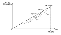
- FIG. 4 is a diagram for explaining a calculation method of the total exhaust gas recirculation rate (hereinafter referred to as “total EGR rate”) REGRT in the present embodiment, and shows the intake pressure PBA and the amount of gas (air amount + air) taken into the engine. (The engine speed NE and the intake valve operating phase CAIN are constant).
- the total EGR rate REGRT is a ratio of the total recirculation exhaust amount due to the internal exhaust recirculation and the external exhaust recirculation via the exhaust recirculation passage 22 to the total intake gas amount (theoretical intake air amount GATH) (the following equations (12) (15 )reference).
- FIG. 1 total exhaust gas recirculation rate
- FIG. 4A corresponds to a state in which the purge control valve 26 is closed and purge gas is not supplied to the intake passage 2 (hereinafter referred to as “purge stop state”), and FIG. This corresponds to a state where the valve is opened and purge gas is supplied to the intake passage 2 (hereinafter referred to as “purge execution state”).
- an operating point PWOT corresponds to a state in which the throttle valve 3 is fully opened, and shows an ideal operating point on the assumption that external exhaust gas recirculation is not performed and internal exhaust gas recirculation is not performed.
- the intake air amount is maximized under a condition where the engine speed NE is constant. Note that the residual gas rate (internal exhaust gas recirculation rate) does not actually become “0” even when the throttle valve 3 is fully opened.
- the intake pressure PBAWOT is substantially equal to the atmospheric pressure PA, the internal exhaust gas recirculation rate is minimized.
- a straight line LTH passing through the operating point PWOT and the origin shows the relationship between the ideal intake air amount and the intake pressure, assuming that external exhaust gas recirculation is not performed and internal exhaust gas recirculation is not performed.
- this straight line LTH is referred to as “theoretical intake air amount straight line LTH”.
- Lines L11 and L12 show a relationship when only internal exhaust gas recirculation is considered, and a relationship when both internal exhaust gas recirculation and external exhaust gas recirculation are considered.
- the lines L11 and L12 are not actually straight lines, but are shown as straight lines for explanation.
- the theoretical intake air amount GATH is given by the following equation (13).
- GPGC in the equation (13) is the amount of purge gas supplied from the evaporated fuel passage 25 to the intake passage 2, and as shown in the following equation (14), the amount of evaporated fuel GVAPOR contained in the purge gas and the fresh air contained in the purge gas.
- the amount (hereinafter referred to as “secondary air amount”) is given by the sum of GPGACYL.
- GINGASCYL in the equation (13) is the sum of the intake air amount GAIRCYL and the purge gas amount GPGC, and is hereinafter referred to as “intake gas amount GINGASCYL”.
- GATH GAIRCYL + GPGC + GEGRIN +
- GEGREX GINGASCYL + GEGRT (13)
- GPGC GVAPOR + GPGACYL (14)
- a corrected intake air amount GAIRCYLC (see FIG. 4B) calculated by adding the secondary fresh air amount GPGACYL to the intake air amount GAIRCYL is used. .
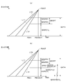
- FIG. 5 is a diagram for explaining a case in which the atmospheric pressure changes.
- the fully open operation point PWOT1 is an operation point corresponding to the reference state
- the intake pressure PBA is a reference intake pressure PBASTD (for example, 100 kPa (750 mmHg)). It corresponds to a certain state.
- PBASTD reference intake pressure
- the operating point PWOT1 moves on the theoretical intake air amount straight line LTH as operating points PWOT2 and PWOT3.
- Curves L21 to L23 starting from the operating points PWOT1 to PWOT3 indicate the intake gas amount GINGASCYL in consideration of internal exhaust gas recirculation (when external exhaust gas recirculation is not performed), respectively.
- TASTD in the equation (16) is the intake air temperature in the reference state (for example, 25 ° C.)
- GAWOTSTD is the intake air amount corresponding to the fully open operation point PWOT in the reference state, and is hereinafter referred to as “reference theoretical fully open air amount GAWOTSTD”.
- GAWOT is the intake air amount corresponding to the fully open operation point PWOT in the operating state of the detected intake air temperature TA, and is referred to as “theoretical fully open air amount Gawot”.
- N is a constant set to a value between “0” and “1” by experiment, and is set to “0.5”, for example.
- a straight line LTHSTD shown in FIG. 6 is a theoretical intake air amount straight line in the reference state, and a straight line LTH is a theoretical intake air amount straight line corresponding to the detected intake air temperature TA.
- FIG. 6 corresponds to an example in which the detected intake air temperature TA is higher than the reference intake air temperature TASTD.
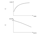
- FIG. 7 is a diagram showing the relationship between the total EGR rate REGRT and the optimal ignition timing IGMBT (the engine speed NE is constant).
- the optimal ignition timing IGMBT is an ignition timing at which the engine output torque becomes maximum.
- symbols ⁇ and ⁇ correspond to operating states where the intake valve operating phase CAIN is 0 degrees
- symbols ⁇ and ⁇ correspond to operating states where the intake valve operating phase CAIN is 20 degrees
- symbols ⁇ and ⁇ Corresponds to an operating state in which the intake valve operating phase CAIN is 45 degrees.
- the symbols ⁇ , ⁇ , and ⁇ correspond to the case where external exhaust gas recirculation is not performed (only internal exhaust gas recirculation), and the symbols ⁇ , ⁇ , and ⁇ indicate external exhaust gas recirculation (internal exhaust gas recirculation + external exhaust gas recirculation)
- the symbols ⁇ , ⁇ , and ⁇ indicate external exhaust gas recirculation (internal exhaust gas recirculation + external exhaust gas recirculation)
- the relationship between the total EGR rate REGRT and the optimal ignition timing IGMBT can be represented by the curve L31 without depending on the operation phase CAIN of the intake valve or the presence or absence of external exhaust gas recirculation. Is done. Therefore, by setting one optimal ignition timing calculation map (IGMBT map) set according to the engine speed NE and the total EGR rate REGRT, the optimal ignition timing corresponding to all operating states can be set. Is possible. Therefore, the map setting man-hour can be significantly reduced.
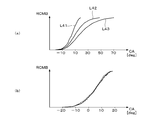
- FIG. 8 is a graph showing a change characteristic (the horizontal axis is the crank angle CA) of the mass combustion ratio RCMB of the air-fuel mixture sucked into the combustion chamber.
- FIG. 5A shows the characteristics when the total EGR rate REGRT is changed with the charging efficiency ⁇ c constant, and the curves L41 to L43 show the total EGR rate REGRT of 6.3%, 16. Corresponding to operating conditions of 2% and 26.3%. Curve L41 means the fastest burning rate. That is, it is confirmed that the total EGR rate REGRT is a main factor that changes the combustion speed of the air-fuel mixture.
- FIG. 8B shows the characteristics (solid line, broken line, and alternate long and short dash line) when the charging efficiency ⁇ c is changed while keeping the total EGR rate constant.
- the solid line, the broken line, and the alternate long and short dash line shown in FIG. Therefore, it can be confirmed that it is appropriate to set the optimal ignition timing IGMBT in accordance with the total EGR rate REGRT, not the charging efficiency ⁇ c (the amount of fresh intake air).
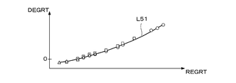
- FIG. 9 is a diagram showing the relationship between the total EGR rate REGRT and the EGR knocking correction amount DEGRT (the engine speed NE is constant).
- the EGR knock correction amount DEGRT is an ignition timing correction amount that is applied to the calculation of the knock limit ignition timing IGKNOCK that indicates the occurrence limit of knocking, and is applied to perform correction corresponding to the change in the recirculation exhaust amount.
- Symbols ⁇ , ⁇ , and ⁇ shown in this figure indicate data corresponding to different filling efficiencies ⁇ c, and it can be confirmed that they do not depend on the filling efficiencies ⁇ c. Therefore, when the engine speed NE is constant, the relationship between the total EGR rate REGRT and the EGR knock correction amount DEGRT can be represented by the curve L51.
- the EGR knock correction amount DEGRT can be appropriately set by using the DEGRT map set according to the engine speed NE and the total EGR rate REGRT.
- the relationship indicated by the curve L51 does not basically depend on the intake valve operation phase CAIN, but it may be necessary to correct the intake valve operation phase CAIN due to variations in engine characteristics. In such a case, a plurality of tables corresponding to the intake valve operating phase CAIN may be provided, or correction corresponding to the intake valve operating phase CAIN may be performed.
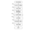
- FIG. 10 is a flowchart of a process for calculating the total EGR rate REGRT. This process is executed by the CPU of the ECU 5 in synchronization with the generation of the TDC pulse.
- step S11 a GAWOTSTD map set according to the engine speed NE and the intake valve operating phase CAIN is searched to calculate a reference theoretical fully-open air amount GAWOTSTD.
- step S12 correction according to the intake air temperature TA according to the above equation (16) is performed, and the theoretical fully-open air amount GAWOT is calculated.
- step S13 the detected intake pressure PBA is applied to the following equation (17) to calculate the theoretical intake air amount GATH.
- GATH GAWOT ⁇ PBA / PBASTD (17)
- step S14 the GAIRCYL calculation process shown in FIG. 11 is executed, and the intake air amount GAIRCYL in one intake stroke of one cylinder is calculated according to the detected intake air flow rate GAIR [g / sec].
- step S15 the purge gas flow rate QPGC calculated in step S68 of FIG. 13 is applied to the following equation (19) to convert it into a purge gas amount GPGC in one intake stroke of one cylinder.
- KC in Expression (19) is a conversion coefficient.
- GPGC QPGC ⁇ KC / NE (19)
- step S16 the intake gas amount GINGACYL is calculated by applying the intake air amount GAIRCYL and the purge gas amount GPGC to the following equation (20).
- GINGASCYL GAIRCYL + GPGC (20)
- step S17 the total EGR rate REGRT is calculated by the equation (15).
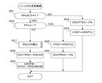
- FIG. 11 is a flowchart of the GAIRCYL calculation process executed in step S14 of FIG.
- the detected intake air flow rate GAIR is applied to the following equation (21) to calculate the detected intake air amount GACYLTMP.
- GACYLTMP GAIR ⁇ KC / NE (21)
- the corrected intake pressure PBAM is calculated by applying the detected intake pressure PBA and the atmospheric pressure PA to the following equation (22).
- PAREF in the equation (22) is a reference atmospheric pressure set to 101.3 kPa, for example.
- PBAM PBA ⁇ PAREF / PA (22)
- a REGRIREF map is searched according to the engine speed NE and the corrected intake pressure PBAM, and a reference internal exhaust gas recirculation rate (hereinafter referred to as “reference internal EGR rate”) REGRIREF is calculated.
- a plurality of REGRIREF maps are set in advance corresponding to a plurality of values of the intake valve operating phase CAIN, and map selection and interpolation calculation are performed according to the intake valve operating phase CAIN (current value).
- the reference internal EGR rate corresponds to an average internal EGR rate in a state where there is no external exhaust gas recirculation via the exhaust gas recirculation passage 22.
- the first basic reference intake air amount GACYLREF1 is calculated by applying the reference internal EGR rate REGRREF and the theoretical intake air amount GATH to the following equation (23).
- the first basic reference intake air amount GACYLREF1 corresponds to a reference value of the intake air amount in a state where external exhaust gas recirculation is not performed.
- GACYLREF1 (1-REGRIREF) ⁇ GATH (23)
- step S105 the first basic reference intake air amount GACYLREF1 and the EGR correction coefficient KEGR are applied to the following equation (24) to calculate the second basic reference intake air amount GACYLREF2.
- the second basic reference intake air amount GACYLREF2 corresponds to a reference value of the intake air amount in consideration of a state in which external exhaust gas recirculation is performed.
- GACYLREF2 GACYLREF1 ⁇ KEGR (24)
- the EGR correction coefficient KEGR is a parameter corresponding to a value (1-REGREXCMD) obtained by subtracting the target value REGREXCMD of the external exhaust gas recirculation rate that is set according to the engine operating state from “1”. When not performed, “1” is set.
- step S106 it is determined whether or not the KAF correction condition flag FKAFCND is “1”.
- the KAF correction condition flag FKAFCND is set to “1” when all of the following conditions 1) to 4) are satisfied.
- the engine 1 is in a predetermined high-load operation state (for example, an operation state in which the charging efficiency is 60% or more).
- the external exhaust gas recirculation rate target value REGREXCMD is equal to or greater than a predetermined value REGREXTH (for example, 0.15).
- REGREXTH for example, 0.15
- the ignition timing knocking retardation correction amount DIGKCS is equal to the maximum retardation amount DIGKMAX.
- the condition 3) is specifically determined as follows. It is determined whether or not the air-fuel ratio determination parameter KAFDET defined by the following equation (25) is within a predetermined abnormal range RABNL defined by (KAFX ⁇ DKAFX), and the air-fuel ratio determination parameter KAFDET is within the predetermined abnormal range RABNL. At some point, it is determined that a secondary air inflow abnormality has occurred.
- KAFDET KAF / KREFX (25)
- KREFX is a learning value of the air-fuel ratio correction coefficient KAF, and is an annealing value (including the latest value) of the air-fuel ratio correction coefficient KAF calculated when the purge gas is not supplied to the intake passage 2 via the evaporated fuel passage 25. A moving average value of a predetermined number of latest calculated values). However, when the intake air amount GAIRCYL is set to the upper limit value GACLMH or the lower limit value GACLML calculated in step S109, the learning value KREFX is held at a value before being set.
- KAFX is a determination reference value calculated by the following equation (26), and DKAFX is a range setting value set to “0.1”, for example.
- the air-fuel ratio determination parameter KAFDET is calculated by the following equation (26). This is based on being substantially equal to the determination reference value KAFX.
- KAFX (GACYLTMP + GEGREXE) / GACYLTMP (26)
- the intake gas amount GGAS corresponds to a gas amount obtained by subtracting the internal recirculation exhaust amount GEGRIN from the theoretical intake air amount GATH, and is set in advance according to the corrected intake pressure PBAM (line L11 shown in FIG. 4B). (Corresponding to the above) is calculated.
- step S106 Normally, the answer to step S106 is negative (NO), the process proceeds to step S107, and the reference intake air amount GACYLREF is set to the second basic reference intake air amount GACYLREF2.
- step S106 If the answer to step S106 is affirmative (YES), that is, if the KAF correction condition flag FKAFCND is “1”, the second basic reference intake air amount GACYLREF2, the air-fuel ratio correction coefficient KAF, and the learning value KREFX are expressed by the following equation (28). Is applied to calculate the reference intake air amount GACYLREF.
- GACYLREF GACYLREF2 ⁇ KAF / KREFX (28)
- step S109 the theoretical intake air amount GATH and the reference intake air amount GACYLREF are calculated using the following equations (29) and (30), respectively, to calculate the intake air amount upper limit value GACLMH and lower limit value GACLML.
- GACLMH CLH ⁇ GATH (29)
- GACLML CLL ⁇ GACYLREF (30)
- CLH and CLL are constants for setting the allowable range, and are set to values of about “1.05” and “0.85”, respectively.
- step S110 it is determined whether or not the retard limit flag FKCSMAX is “1”.
- the retard limit flag FKCSMAX is set to “1” when the ignition timing knocking retard correction amount DIGKCS is equal to the maximum retard amount DIGKMAX. If the answer to step S110 is affirmative (YES), it is determined whether or not the detected intake air amount GACYLTMP is greater than the lower limit value GACLML calculated in step S109 (step S112). When this answer is negative (NO), that is, when GACYLTMP ⁇ GACLML, the intake air amount GAIRCYL is set to the reference intake air amount GACYLREF (step S114), and the switching flag FEATM indicating that is set to “1”. (Step S115). On the other hand, if the answer to step S112 is affirmative (YES), the switching flag FEATM is set to “0” (step S113), and the process proceeds to step S116.
- step S110 If the answer to step S110 is negative (NO) and the knocking retardation correction amount DIGKCS has not reached the maximum retardation amount DIGKMAX, it is determined whether or not the switching flag FEATM is “1” (step S111). ). When the answer is affirmative (YES), the process proceeds to step S112, and when the switching flag FEATM is “0”, the process proceeds to step S116.
- step S116 to S120 limit processing of the detected intake air amount GACYLTMP is performed to calculate the intake air amount GAIRCYL. That is, when the detected intake air amount GACYLTMP is larger than the upper limit value GACLMH, the intake air amount GAIRCYL is set to the upper limit value GACLMH (steps S116 and S117), and when the detected intake air amount GACYLTMP is smaller than the lower limit value GACLML, the intake air amount GAIRCYL is set. Is set to the lower limit value GACLML (steps S118 and S120), and when the detected intake air amount GACYLTMP is within the upper and lower limit values, the intake air amount GAIRCYL is set to the detected intake air amount GACYLTMP (step S119).
- transient control for gradually shifting the intake air amount GAIRCYL from the reference intake air amount GACYLREF to the detected intake air amount GACYLTMP is performed. Done.
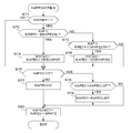
- FIG. 12 is a flowchart of a process for performing purge gas flow rate control, that is, opening degree control of the purge control valve 26. This process is executed every predetermined time (for example, 80 msec) by the CPU of the ECU 5.
- step S51 it is determined whether or not the purge execution flag FPGAACT is “1”.
- the purge execution flag FPGAACT is set to “1” when in an operation state in which purge gas is supplied to the intake passage 2. If the answer to step S51 is negative (NO), the purge control valve drive duty DOUTPGC is set to “0” (step S52), and then the transient control coefficient KPGT is set to a predetermined initial value KPGTINI ( ⁇ 1.0). (Step S53).
- the transient control coefficient KPGT is a coefficient for limiting the purge gas flow rate at the beginning of the supply of the purge gas, and is set so as to increase with the passage of time until reaching “1.0” after the purge gas supply is started (FIG. 13, see steps S65 to S67).
- step S54 When the answer to step S51 is affirmative (YES), that is, when purge gas is supplied, it is determined whether or not the fuel cut flag FFC is “1” (step S54).
- the fuel cut flag FFC is set to “1” in an operation state in which fuel supply to the engine 1 is temporarily stopped.
- the transient control coefficient KPGT is set to a predetermined initial value KPGTINI, and the purge control valve drive duty DOUTPGC is set to “0” (steps S55 and S56).
- step S54 the PGCMD calculation process shown in FIG. 13 is executed to calculate the target drive duty PGCMD (step S57).
- step S58 the purge control valve drive duty DOUTPGC is set to the target drive duty PGCMD.
- step S59 the purge gas flow rate QPGC and the basic purge gas flow rate QPGCBASE calculated in the process of FIG. 13 are applied to the following equation (31) to calculate the purge gas flow rate ratio QRATE.
- QRATE QPGC / QPGCBASE (31)
- FIG. 13 is a flowchart of the PGCMD calculation process executed in step S57 of FIG.
- the detected intake air flow rate GAIR is applied to the following equation (32) to calculate the basic purge gas flow rate QPGCBASE.
- KQPGB in the equation (32) is a predetermined target purge rate.
- QPGCBASE GAIR ⁇ KQPGB (32)
- step S62 it is determined whether or not the basic purge gas flow rate QPGCBASE is larger than the upper limit value QPGMAX. If the answer is negative (NO), the target purge gas flow rate QPGCMD is set to the basic purge gas flow rate QPGCBASE (step S63). When the basic purge gas flow rate QPGCBASE is larger than the upper limit value QPGMAX, the target purge gas flow rate QPGCMD is set to the upper limit value QPGMAX (step S64).
- step S65 the transient control coefficient KPGT is increased by a predetermined amount DKKGT ( ⁇ 1.0).
- step S66 it is determined whether or not the transient control coefficient KPGT is greater than “1.0”. If the answer to step S66 is negative (NO), the process immediately proceeds to step S68. If the answer to step S66 is affirmative (YES), the transient control coefficient KPGT is set to “1.0” (step S67), and the process proceeds to step S68.
- step S68 the target purge gas flow rate QPGCMD and the transient control coefficient KPGT are applied to the following equation (33) to calculate the purge gas flow rate QPGC.
- QPGC QPGCMD ⁇ KPGT (33)
- step S69 the purge gas flow rate QPGC is applied to the following equation (34) to convert the purge gas flow rate QPGC into the target drive duty PGCMD.
- KDUTY is a predetermined conversion coefficient
- KDPBG is a differential pressure coefficient set according to the differential pressure between the intake pressure PBA and the atmospheric pressure PA.
- PGCMD QPGC ⁇ KDUTY / KDPBG (34)
- the purge gas flow rate ratio QRATE calculated in step S59 of FIG. 12 is when the transient control coefficient KPGT is smaller than “1.0” and the basic purge gas flow rate QPGCBASE is larger than the upper limit value QPGMAX. The value is smaller than “1.0”, and “1.0” is taken otherwise.
- FIG. 14 is a flowchart of the process for calculating the evaporated fuel concentration coefficient KAFEVACT indicating the evaporated fuel concentration in the purge gas. This process is executed every predetermined time (for example, 80 msec) by the CPU of the ECU 5.
- step S71 it is determined whether or not the feedback control flag FAFFB is “1”.
- the feedback control flag FAFFB is set to “1” when executing the air-fuel ratio feedback control for matching the air-fuel ratio (KACT) detected by the LAF sensor 24 with the target air-fuel ratio (KCMD). If the answer to step S71 is negative (NO), the process immediately proceeds to step S76.
- step S71 If the answer to step S71 is affirmative (YES) and air-fuel ratio feedback control is being performed, it is determined whether or not the air-fuel ratio correction coefficient KAF is smaller than a value obtained by subtracting the lower deviation DKAFEXL from the learning value KREFX. (Step S72).
- the lower deviation DKAFEVXL is a parameter for determining a shift in the decreasing direction of the air-fuel ratio correction coefficient KAF due to the supply of purge gas, and is set to a smaller value as the intake air flow rate GAIR increases.
- step S72 When the answer to step S72 is affirmative (YES) and the deviation in the decreasing direction of the air-fuel ratio correction coefficient KAF due to the purge gas supply is large, it is determined that the evaporated fuel concentration in the purge gas is high, and the basic equation (35) below is used.
- the density coefficient KAFEV is increased by a predetermined addition amount DKEVAPOP (step S74).
- KAFEV KAFEV + DKEVAPOP (35)
- step S73 it is determined whether or not the air-fuel ratio correction coefficient KAF is greater than a value obtained by adding the upper deviation DKAFEVXH to the learning value KREFX (step S73).
- the upper deviation DKAFEVXH is a parameter for determining a deviation in the increasing direction of the air-fuel ratio correction coefficient KAF due to the purge gas supply, and is set to a smaller value as the intake air flow rate GAIR increases.
- step S73 If the answer to step S73 is affirmative (YES), and the deviation in the increasing direction of the air-fuel ratio correction coefficient KAF due to the supply of the purge gas is large, it is determined that the evaporated fuel concentration in the purge gas is low, and the basic equation The density coefficient KAFEV is decreased by a predetermined subtraction amount DKEVAPOM (step S75).
- KAFEV KAFEV ⁇ DKEVAPOM (36)
- step S73 If the answer to step S73 is negative (NO), the process proceeds to step S76 without updating the basic concentration coefficient KAFEV.
- step S76 it is determined whether or not the basic concentration coefficient KAFEV is greater than “0”. If the answer is negative (NO), the basic concentration coefficient KAFEV is set to “0” (step S77). When the basic density coefficient KAFEV is larger than “0”, it is further determined whether or not it is larger than the upper limit coefficient value KAFEVLMT (step S78). If the answer is affirmative (YES), the basic density coefficient KAFEV is set to the upper limit coefficient value KAFEVLMT (step S79), and the process proceeds to step S80. If the answer to step S78 is negative (NO), the process immediately proceeds to step S80.
- step S80 the basic concentration coefficient KAFEV and the purge gas flow rate ratio QRATE are applied to the following equation (37) to calculate the evaporated fuel concentration coefficient KAFEVACT.
- KAFEVACT KAFEV ⁇ QRATE (37)
- FIG. 15 is a flowchart of processing for calculating the ignition timing IGLOG indicated by the advance amount from the compression top dead center. This process is executed by the CPU of the ECU 5 in synchronization with the generation of the TDC pulse.
- step S21 an IGMBT map (see FIG. 7) is searched according to the engine speed NE and the total EGR rate REGRT, and the optimal ignition timing IGMBT is calculated.
- step S22 the IGKNOCK calculation process shown in FIG. 16 is executed to calculate the knock limit ignition timing IGKNOCK.
- step S23 it is determined whether or not the optimal ignition timing IGMBT is equal to or greater than the knock limit ignition timing IGKNOCK. If the answer is affirmative (YES), the basic ignition timing IGB is set to the knock limit ignition timing IGKNOCK (Ste S24). When the optimum ignition timing IGMBT is smaller than the knock limit ignition timing IGKNOCK in step S23, the basic ignition timing IGB is set to the optimum ignition timing IGMBT (step S25).
- step S26 the ignition timing IGLOG is calculated by adding a correction value IGCR calculated according to, for example, the engine coolant temperature TW to the basic ignition timing IGB.
- the CPU of the ECU 5 performs ignition by the spark plug 15 according to the calculated ignition timing IGLOG.
- FIG. 16 is a flowchart of the IGKNOCK calculation process executed in step S22 of FIG.
- the GAIRCYLC calculation process shown in FIG. 17 is executed to calculate the corrected intake air amount GAIRCYLC.
- the purge gas amount GPGC and the evaporated fuel concentration coefficient KAFEVACT are applied to the following equation (41) to calculate the secondary fresh air amount GPGACYL indicating the fresh air amount contained in the barge gas.
- GPGACYL GPGC ⁇ (1-KAFEVACT) (41)
- step S92 the corrected intake air amount GAIRCYLC is calculated by adding the secondary fresh air amount GPGACYL to the intake air amount GAIRCYL (the following equation (42)).
- GAIRCYLC GAIRCYL + GPGACYL (42)
- an IGKNOCKB map is searched according to the engine speed NE and the corrected intake air amount GAIRCYLC to calculate the basic knock limit ignition timing IGKNOCKB.
- the IGKNOCKB map is set corresponding to a state in which the total EGR rate REGRT is set to a predetermined reference value and the intake valve operating phase CAIN is set to “0 degree”.
- step S32 the CMPR table shown in FIG. 18A is retrieved according to the intake valve operating phase CAIN to calculate the effective compression ratio CMPR.
- the intake valve operation phase CAIN changes, the intake valve closing timing CACL changes, and the effective compression ratio CMPR changes.
- the CMPR table a relationship between the intake valve operating phase CAIN calculated in advance and the effective compression ratio CMPR is set.
- step S33 a DCMPR map is searched according to the effective compression ratio CMPR and the engine speed NE, and a compression ratio knocking correction amount DCMPR is calculated.
- the compression ratio knocking correction amount DCMPR takes a value of “0” or less, and is set to decrease as the effective compression ratio CMPR increases.
- a method for calculating the effective compression ratio CMPR is shown in International Publication No. WO2011 / 074302.
- step S34 a DEG map is searched according to the total EGR rate REGRT and the engine speed NE, and an EGR knock correction amount DEGRT is calculated.
- the EGR knock correction amount DEGRT takes a value larger than “0”, and is set to increase as the total EGR rate REGRT increases as shown in FIG.
- step S35 the knocking retardation correction amount DIGKCS is calculated based on the detection result of the knocking detection process (not shown) based on the output of the knock sensor 14.
- the knocking retardation correction amount DIGKCS increases when knocking is detected, and a retardation coefficient KCS (set to a value between 0 and 1) calculated so as to gradually decrease during a period when knocking is not detected. Is calculated by multiplying the maximum retardation amount DIGKMAX.
- the calculation method of the knocking retardation correction amount DIGKCS according to the knocking occurrence state is a known method, and is disclosed in, for example, Japanese Patent No. 4087265.
- step S36 the basic knock limit ignition timing IGKNOCKB, the compression ratio knock correction amount DCMPR, the EGR knock correction amount DEGRT, and the knock retardation correction amount DIGKCS are applied to the following equation (43) to calculate the knock limit ignition timing IGKNOCK.
- IGKNOCK IGKNOCKB + DCMPR + DEGRT -DIGKCS (43)
- the valve opening time of the fuel injection valve 6, that is, the fuel injection amount TOUT is also calculated using the total EGR rate REGRT.
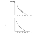
- FIG. 19 is a diagram showing the relationship between the charging efficiency ⁇ c and the basic knock limit ignition timing IGKNOCKB.
- the solid line shown in FIG. 19A indicates the basic knock limit ignition timing IGKNOCKB according to the intake air amount GAIRCYL when the purge gas is supplied.
- the solid line shown in FIG. 19B shows an example in which the basic knock limit ignition timing IGKNOCKB is calculated according to the corrected intake air amount GAIRCYLC when the purge gas is supplied.
- the symbols ⁇ and ⁇ shown in FIG. 19 indicate the actual knock limit ignition timing, and correspond to the state in which the purge gas flows in 25% and the state in which 75% flows in, respectively. That is, when the basic knock limit ignition timing IGKNOCKB is calculated according to the intake air amount GAIRCYL, the basic knock limit ignition timing IGKNOCKB becomes a value retarded from the actual knock limit ignition timing, and the basic knock limit ignition timing IGKNOCKB Setting error increases.
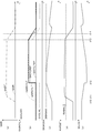
- FIG. 20 is a time chart showing a first control operation example, in which detected intake air amount flow rate GAIR (FIG. (A)), calculated intake air amount GAIRCYL (FIG. (B)), ignition timing knocking. Changes in the retard correction amount DIGKCS (FIG. (C)) and the ignition timing IGLOG ((d)) are shown.
- This example corresponds to a state in which fresh air inflow occurs due to a failure of the intake air flow rate sensor 13 or an abnormality (displacement of piping) of the evaporated fuel passage 25.
- a dashed line in FIG. 20A indicates the true intake air flow rate GAIRT.
- the intake air amount GAIRCYL is set to the detected intake air amount GACYLTMP until time t1, and thus decreases in the same manner as the detected intake air amount flow rate GAIR.
- the lower limit value GACLML is set. Therefore, the ignition timing IGLOG increases corresponding to the decrease in the detected intake air amount GACYLTMP until just before time t1.
- the knocking retardation correction amount DIGKCS gradually increases after time t0, the ignition timing IGLOG decreases slightly before time t1.
- the knocking retardation correction amount DIGKCS reaches the maximum retardation amount DIGKMAX (retarding limit value) at time t2.
- the answer to step S110 in FIG. 11 is affirmative (YES)
- the answer to step S112 is negative (NO) (GACYLTMP ⁇ GACLML)
- the intake air amount GACYL is set to the reference intake air amount GACYLREF.
- the ignition timing IGLOG changes stepwise to a value corresponding to the reference intake air amount GACYLREF, and the knocking retardation correction amount DIGKCS gradually decreases after time t2.
- the detected intake air flow rate GAIR starts increasing, and at time t4, the detected intake air amount GACYLTMP exceeds the lower limit GACLML, so that the answer to step S112 in FIG. 11 becomes affirmative (YES). Accordingly, the intake air amount GAIRCYL gradually shifts to the detected intake air amount GACYLTMP.
- the knocking retardation correction amount DIGKCS gradually decreases from time t2 to time t4, and changes with change in the intake air amount GAIRCYL slightly after time t4.
- the second basic reference intake air amount GACYLREF2 calculated according to the corrected intake pressure PBAM substantially matches the true intake air amount
- the answer to step S106 in FIG. 11 is negative (NO).
- the reference intake air amount GACYLREF is set to the second basic reference intake air amount GACYLREF2.
- the intake air amount GAIRCYL is set to the reference intake air amount GACYLREF, so that the occurrence of knocking is prevented (therefore, the knocking retardation correction amount DIGKCS gradually decreases).
- FIG. 21 is a time chart showing a second control operation example, in which detected intake air amount flow rate GAIR (FIG. (A)), calculated intake air amount GAIRCYL (FIG. (B)), ignition timing knocking. Changes in the retardation correction amount DIGKCS ((c) in the figure), the air-fuel ratio determination parameter KAFDET ((d) in the same figure), and the ignition timing IGLOG ((e) in the same figure) are shown.
- This example corresponds to a state in which inflow of fresh air occurs due to an abnormality in the exhaust gas recirculation passage 22 (displacement of piping).
- the alternate long and short dash lines in FIGS. 21A and 21B indicate the intake air flow rate GAIRT and the corresponding true intake air amount GAIRCYLT, respectively.
- the corrected intake pressure PBAM is substantially the same as the state in which the exhaust gas recirculation passage 22 is normal and the exhaust gas recirculation is performed, so the second basic reference intake air calculated according to the corrected intake pressure PBAM.
- the air-fuel ratio determination parameter KAFDET enters the predetermined abnormal range RABLN (KAFX ⁇ DKAFX) slightly before time t11.
- the knocking retardation correction amount DIGKCS gradually increases after time t10 and reaches the maximum retardation amount DIGKMAX at time t12 because the intake air amount GAIRCYL is deviated from the true intake air amount GAIRCYLT.
- Step S108 the lower limit GACLML is increased, the answer to step S112 is negative (NO), and the intake air amount GAIRCYL is set to the reference intake air amount GACYLREF calculated in step S108 (step S114). Therefore, the intake air amount GAIRCYL and the reference intake air amount GACYLREF substantially coincide with the true intake air amount GAIRCYLT.
- step S112 in FIG. 11 is affirmative (YES). Accordingly, the intake air amount GAIRCYL gradually shifts to the detected intake air amount GACYLTMP.
- the knocking retardation correction amount DIGKCS gradually decreases from a little later than time t12 to time t14, and changes with a change in the intake air amount GAIRCYL slightly after time t14.
- the intake air amount GAIRCYL is set to the reference intake air amount GACYLREF, so that the occurrence of knocking is prevented (therefore, the knocking retardation correction amount DIGKCS gradually decreases).
- the second basic reference intake air amount GAIRCREF2 calculated in accordance with the corrected intake pressure PBAM cannot approximate the true intake air amount GAIRCYLT.
- appropriate control is performed using the intake air amount GAIRCYL set to a value close to the true intake air amount GAIRCYLT. It can be carried out.
- the theoretical fully open air amount GAWOT which is the intake air amount corresponding to the state in which the throttle valve 3 is fully opened, is calculated according to the intake valve operating phase CAIN and the engine speed NE, and the recirculation exhaust gas
- the theoretical intake air amount GATH corresponding to the virtual state in which the amount is “0” is calculated according to the theoretical fully open air amount GAWOT and the intake pressure PBA.
- the purge gas amount GPGC supplied to the intake passage 2 via the vaporized fuel passage 25 is calculated, the intake air amount GAIRCYL is corrected using the purge gas amount GPGC, the intake gas amount GINGASCYL is calculated, and the intake gas amount GINGASCYL is theoretically calculated.
- the total EGR rate REGRT is calculated using the intake air amount GATH, and the ignition timing control is performed using the total EGR rate REGRT. Further, the air-fuel ratio correction coefficient KAF is calculated according to the detected equivalent ratio KACT, and the learning value KREFX of the air-fuel ratio correction coefficient KAF is calculated, and the corrected intake pressure PBAM, the engine speed NE, the air-fuel ratio correction coefficient KAF, and the learning
- the reference intake air amount GACYLREF is calculated using the value KREFX
- the lower limit value GACLML of the intake air amount is calculated according to the reference intake air amount GACYLREF
- the upper limit value GACLMH is calculated according to the theoretical intake air amount GATH. Then, limit processing is performed to limit the detected intake air amount GACYLTMP within the upper and lower limits GACLMH and GACLML.
- the lower limit GACLML is set using the corrected intake pressure PBAM and the engine speed NE, the air-fuel ratio correction coefficient KAF reflecting the actual air-fuel ratio of the combustion mixture, and its learned value KREFX, for example, intake air
- limit processing is appropriately performed to limit the detected intake air amount GACYLTMP to a range equal to or greater than the lower limit GACLML. It is possible to avoid a situation in which the timing control accuracy is greatly deteriorated.
- the total EGR rate REGRT is calculated using the intake gas amount GINGASCYL corrected by the purge gas amount GPGC supplied to the intake passage 2 via the evaporated fuel passage 25, it is accurate even when the purge gas is supplied. An exhaust gas recirculation rate can be obtained.
- the knocking retardation correction amount DIGKCS is calculated so as to increase as the detection frequency of knocking increases, and the ignition timing control is performed using the knocking retardation correction amount DIGKCS.
- the knocking retardation correction amount DIGKCS reaches the maximum retardation amount DIGKMAX, fail-safe processing is performed in which the intake air amount GAIRCYL is replaced with the reference intake air amount GACYLREF, so that the detected intake air amount GACYLTMP is the actual intake air amount. The occurrence of knocking can be reliably prevented in a state greatly deviated from GAIRCYLT.
- an estimated recirculation gas amount GEGREX which is an estimated value of the gas amount flowing into the intake passage 2 via the exhaust recirculation passage 22, is calculated, and the air-fuel ratio determination parameter KAFDET is determined according to the detected intake air amount GACYLTMP and the estimated recirculation gas amount GEGREXE. It is determined that the exhaust gas recirculation passage 22 is abnormal when it is within the predetermined range RABNL (KAFX ⁇ DKAFX) set in the above.
- the engine 1 is in a predetermined high load operation state, and the exhaust gas recirculation passage 22 is abnormal, and the knocking delay is delayed.
- the angle correction amount DIGKCS reaches the maximum retardation amount DIGKMAX, a fail-safe process is performed in which the intake air amount GAIRCYL is replaced with the reference intake air amount GACYLREF corrected using the air-fuel ratio determination parameter KAFDET.
- the second basic reference intake air amount GACYLREF2 calculated according to the corrected intake pressure PBAM greatly deviates from the actual intake air amount GAIRCYLT.
- the reference intake air amount GACYLREF corrected by multiplication the actual intake air amount GAIRCYLT can be accurately approximated. Therefore, when the intake air amount GAIRCYL is replaced with the corrected reference intake air amount GACYLREF, the exhaust gas recirculation passage 22 is disconnected and fresh air flows into the intake passage 2 from the exhaust gas recirculation passage 22. The occurrence of knocking can be reliably prevented.
- the air-fuel ratio determination parameter KAFDET obtained by dividing the air-fuel ratio correction coefficient KAF by the learned value KREFX, the influence of the characteristic variation of the fuel injection valve 6 and the intake air flow rate sensor 13 is eliminated, and the accuracy is high. Corrections can be made.
- the optimal ignition timing IGMBT is calculated according to the total EGR rate REGRT, it is possible to obtain a highly accurate optimal ignition timing IGMBT that takes into account the internal exhaust gas recirculation. Further, since it has been confirmed that the relationship between the total EGR rate REGRT and the optimal ignition timing IGMBT is not influenced by the intake valve operating phase CAIN or the presence or absence of the external exhaust gas recirculation (FIG. 7), the relationship between the total EGR rate REGRT and the optimal ignition timing IGMBT By setting the optimal ignition timing IGMBT, the optimal ignition timing IGMBT suitable for the engine operating state can be easily calculated. Then, by performing the ignition timing control using the calculated optimal ignition timing IGMBT, the engine output performance can be sufficiently exhibited.
- an evaporated fuel concentration coefficient KAFEVACT indicating the evaporated fuel concentration in the purge gas is calculated, and the intake air amount GAIRCYL is corrected using the secondary fresh air amount GPGACYL calculated in accordance with the purge gas amount GPGC and the evaporated fuel concentration coefficient KAFEVACT.
- the corrected intake air amount GAIRCYLC is calculated, and the basic knock limit ignition timing IGKNOCKB is calculated according to the engine speed NE and the corrected intake air amount GAIRCYLC.
- the EGR knock correction amount DEGRT is calculated according to the total EGR rate REGRT, and the knock limit ignition timing IGKNOCK is calculated by correcting the basic knock limit ignition timing IGKNOCKB with the EGR knock correction amount DEGRT.
- the knock limit ignition timing IGKNOCK is highly correlated with the total EGR rate REGRT (see FIG. 9), knocking is reliably avoided by performing correction using the EGR knock correction amount DEGRT calculated according to the total EGR rate REGRT. Ignition timing control that maximizes the engine output within a possible range can be performed with high accuracy.
- the purge gas is supplied to the intake passage 2 via the evaporated fuel passage 25, the amount of fresh air sucked into the cylinder is obtained by adding the secondary fresh air amount GPGACYL to the intake air amount GAIRCYL.
- the compression ratio knocking correction amount DCMPR is calculated according to the intake valve operating phase CAIN, and the basic knock limit ignition timing IGKNOCKB is corrected by the compression ratio knocking correction amount DCMPR. Therefore, the intake valve operating phase CAIN is set according to the engine operating state. Even in the case of changing, the accurate knock limit ignition timing IGKNOCK can be obtained.
- the effective compression ratio CMPR of the engine is calculated according to the intake valve operating phase CAIN, and the compression ratio knocking correction amount DCMPR is calculated according to the effective compression ratio CMPR. Since the knock limit ignition timing IGKNOCK changes depending on the effective compression ratio CMPR, the effective compression ratio CMPR is calculated according to the intake valve operating phase CAIN, and the basic knock limit ignition timing IGKNOCKB is corrected according to the effective compression ratio CMPR. By doing so, more appropriate correction can be performed.
- the crank angle position sensor 11 and the intake pressure sensor 8 correspond to the rotational speed detection means and the intake pressure detection means
- the intake air flow rate sensor 13 corresponds to the intake air amount detection means
- the LAF sensor 24 is empty.
- the knock sensor 14 constitutes part of the knocking detection means
- the ECU 5 is a fully open intake air amount calculation means, a theoretical intake air amount calculation means, an evaporated fuel mixture amount calculation means, and an intake gas amount calculation.
- steps S11 and S12 in FIG. 10 correspond to the fully-open intake air amount calculating means
- step S13 corresponds to the theoretical intake air amount calculating means
- step S15 corresponds to the intake gas amount calculating means
- step S15 corresponds to the intake gas amount calculating means
- steps S102 to S108 in FIG. 11 correspond to the reference intake air amount calculation means
- step S109 corresponds to the lower limit value setting means
- steps S118 to S120 correspond to the limit processing means.
- Steps S110 to S115 correspond to fail-safe processing means
- steps S61 to S68 in FIG. 13 correspond to evaporated fuel mixture amount calculating means
- the processing in FIG. 14 corresponds to evaporated fuel concentration calculating means.
- Step S21 corresponds to the optimum ignition timing calculation means
- the processing in FIG. 16 corresponds to the knock limit ignition timing calculation means
- the processing in FIG. It corresponds to a positive intake air amount calculation means.
- the process shown in FIG. 11 may be modified as shown in FIG.
- the process in FIG. 22 is obtained by deleting step S104 in FIG. 11 and replacing step S103 with step S103a.
- step S103a the first basic reference intake air amount GACYLREF1 is calculated by searching the GACYLREF1 map according to the engine speed NE and the corrected intake pressure PBAM (and the intake valve operating phase CAIN).
- the GACYLREF1 map corresponds to a map in which the first basic reference intake air amount GACYLREF1 calculated in steps S103 and S104 in FIG. 11 is set.
- the present invention is also applicable to control of an internal combustion engine.
- the effective compression ratio CMPR is calculated according to the intake valve operating phase CAIN, and the compression ratio knocking correction amount DCMPR is calculated according to the effective compression ratio CMPR. Accordingly, the compression ratio knocking correction amount DCMPR may be calculated directly.
- the present invention can also be applied to control of an internal combustion engine in which the intake valve operating phase is fixed.
- the present invention can also be applied to the control of a marine vessel propulsion engine such as an outboard motor having a vertical crankshaft.
Landscapes
- Engineering & Computer Science (AREA)
- General Engineering & Computer Science (AREA)
- Chemical & Material Sciences (AREA)
- Combustion & Propulsion (AREA)
- Mechanical Engineering (AREA)
- Signal Processing (AREA)
- Theoretical Computer Science (AREA)
- Combined Controls Of Internal Combustion Engines (AREA)
- Output Control And Ontrol Of Special Type Engine (AREA)
- Electrical Control Of Air Or Fuel Supplied To Internal-Combustion Engine (AREA)
- Supplying Secondary Fuel Or The Like To Fuel, Air Or Fuel-Air Mixtures (AREA)
- Electrical Control Of Ignition Timing (AREA)
- Exhaust-Gas Circulating Devices (AREA)
Priority Applications (4)
| Application Number | Priority Date | Filing Date | Title |
|---|---|---|---|
| EP12865979.4A EP2806146B8 (de) | 2012-01-19 | 2012-10-19 | Vorrichtung zur steuerung eines verbrennungsmotors |
| JP2013554185A JP5547858B2 (ja) | 2012-01-19 | 2012-10-19 | 内燃機関の制御装置 |
| US14/364,500 US8918269B2 (en) | 2012-01-19 | 2012-10-19 | Control apparatus for internal combustion engine |
| CN201280064387.6A CN104011356B (zh) | 2012-01-19 | 2012-10-19 | 内燃机的控制装置 |
Applications Claiming Priority (2)
| Application Number | Priority Date | Filing Date | Title |
|---|---|---|---|
| JP2012-008563 | 2012-01-19 | ||
| JP2012008563 | 2012-01-19 |
Publications (1)
| Publication Number | Publication Date |
|---|---|
| WO2013108455A1 true WO2013108455A1 (ja) | 2013-07-25 |
Family
ID=48798892
Family Applications (1)
| Application Number | Title | Priority Date | Filing Date |
|---|---|---|---|
| PCT/JP2012/077074 Ceased WO2013108455A1 (ja) | 2012-01-19 | 2012-10-19 | 内燃機関の制御装置 |
Country Status (5)
| Country | Link |
|---|---|
| US (1) | US8918269B2 (de) |
| EP (1) | EP2806146B8 (de) |
| JP (1) | JP5547858B2 (de) |
| CN (1) | CN104011356B (de) |
| WO (1) | WO2013108455A1 (de) |
Cited By (2)
| Publication number | Priority date | Publication date | Assignee | Title |
|---|---|---|---|---|
| WO2020246286A1 (ja) * | 2019-06-04 | 2020-12-10 | 愛三工業株式会社 | スロットル制御装置 |
| CN112780420A (zh) * | 2019-11-07 | 2021-05-11 | 丰田自动车株式会社 | 发动机控制装置、发动机控制方法以及存储介质 |
Families Citing this family (27)
| Publication number | Priority date | Publication date | Assignee | Title |
|---|---|---|---|---|
| WO2011074302A1 (ja) * | 2009-12-18 | 2011-06-23 | 本田技研工業株式会社 | 内燃機関の制御装置 |
| JP5511989B2 (ja) * | 2011-01-07 | 2014-06-04 | 本田技研工業株式会社 | 内燃機関の制御装置 |
| US9222426B2 (en) * | 2012-02-17 | 2015-12-29 | Ford Global Technologies, Llc | Transient air flow control |
| KR101481303B1 (ko) * | 2013-08-09 | 2015-01-09 | 현대자동차주식회사 | Egr시스템 진단방법 |
| JP6088397B2 (ja) * | 2013-10-15 | 2017-03-01 | 日本特殊陶業株式会社 | 点火時期制御装置および点火時期制御システム |
| JP6462311B2 (ja) | 2014-10-24 | 2019-01-30 | 日立オートモティブシステムズ株式会社 | エンジンの制御装置 |
| DE102015202180A1 (de) * | 2015-02-06 | 2016-08-11 | Robert Bosch Gmbh | Verfahren zur Regelung |
| JP6213507B2 (ja) * | 2015-03-19 | 2017-10-18 | トヨタ自動車株式会社 | 内燃機関の制御装置 |
| JP6350431B2 (ja) * | 2015-07-28 | 2018-07-04 | トヨタ自動車株式会社 | 内燃機関の制御装置 |
| JP2017078378A (ja) * | 2015-10-21 | 2017-04-27 | 株式会社デンソー | 診断装置 |
| KR20170070876A (ko) * | 2015-12-14 | 2017-06-23 | 현대자동차주식회사 | 차량의 시동꺼짐 방지방법 |
| FR3047517B1 (fr) * | 2016-02-04 | 2018-03-02 | Peugeot Citroen Automobiles Sa | Procede de recalage en fonction de la temperature d’un capteur de pression dans une ligne d’admission d’air d’un moteur |
| DE102016002361A1 (de) | 2016-02-26 | 2017-08-31 | GM Global Technology Operations LLC (n. d. Ges. d. Staates Delaware) | Steuern einer Brennkraftmaschine mit verstellbarer Nockenwelle |
| US10914264B2 (en) * | 2016-06-23 | 2021-02-09 | Toyota Jidosha Kabushiki Kaisha | Air-fuel ratio control apparatus and method for internal combustion engine |
| CN107882648B (zh) * | 2016-09-30 | 2020-01-31 | 长城汽车股份有限公司 | 具有低压egr系统的egr率控制方法、系统及车辆 |
| JP6606525B2 (ja) * | 2017-05-12 | 2019-11-13 | 本田技研工業株式会社 | 内燃機関の制御装置 |
| DE102018106849A1 (de) * | 2018-03-22 | 2019-09-26 | Volkswagen Aktiengesellschaft | Verfahren und Regelkreis zum Bestimmen einer Stellgröße zum Einstellen eines Saugrohrdrucks |
| JP6958477B2 (ja) * | 2018-05-11 | 2021-11-02 | トヨタ自動車株式会社 | ハイブリッド車両の制御システム |
| US10746123B2 (en) * | 2018-08-21 | 2020-08-18 | Cummins Inc. | Deep reinforcement learning for air handling and fuel system referencing |
| US11739701B2 (en) * | 2018-11-08 | 2023-08-29 | Marelli Europe S.P.A. | Method to determine the mass of air trapped in each cylinder of an internal combustion engine |
| KR102692479B1 (ko) * | 2018-12-17 | 2024-08-07 | 현대자동차주식회사 | 가변 밸브 듀레이션 기구 및 액티브 퍼지 시스템을 구비한 차량의 공연비 제어 방법 |
| IT201900004879A1 (it) * | 2019-04-01 | 2020-10-01 | Magneti Marelli Spa | Metodo per il controllo della combustione di un motore a combustione interna |
| CN112145325B (zh) * | 2019-06-28 | 2022-04-05 | 联合汽车电子有限公司 | 发动机进气系统管路诊断方法 |
| JP2021032114A (ja) * | 2019-08-22 | 2021-03-01 | トヨタ自動車株式会社 | 車両用学習制御システム、車両用制御装置、および車両用学習装置 |
| CN115443376B (zh) * | 2021-04-02 | 2023-11-14 | 日产自动车株式会社 | 车辆的异常诊断方法以及车辆的异常诊断装置 |
| CN113187617B (zh) * | 2021-04-28 | 2022-08-05 | 潍柴动力股份有限公司 | 发动机保护控制方法、装置、设备及存储介质 |
| CN114673603B (zh) * | 2022-04-12 | 2023-04-14 | 中国第一汽车股份有限公司 | 发动机控制系统安全监控方法、装置、计算机设备和介质 |
Citations (9)
| Publication number | Priority date | Publication date | Assignee | Title |
|---|---|---|---|---|
| JP2000227013A (ja) | 1999-02-05 | 2000-08-15 | Honda Motor Co Ltd | 内燃機関の動弁制御装置 |
| JP2002147279A (ja) * | 2000-11-08 | 2002-05-22 | Toyota Motor Corp | 吸入空気量算出装置及び吸気圧算出装置 |
| JP2005325762A (ja) | 2004-05-14 | 2005-11-24 | Denso Corp | 内燃機関の空燃比制御装置 |
| JP2006258029A (ja) * | 2005-03-18 | 2006-09-28 | Honda Motor Co Ltd | 蒸発燃料処理装置の故障診断装置 |
| JP2006328963A (ja) * | 2005-05-23 | 2006-12-07 | Toyota Motor Corp | 内燃機関の燃料噴射制御装置 |
| JP2007297955A (ja) * | 2006-04-28 | 2007-11-15 | Denso Corp | 内燃機関の蒸発燃料処理装置 |
| JP4087265B2 (ja) | 2003-02-21 | 2008-05-21 | 本田技研工業株式会社 | 内燃機関の点火時期制御装置 |
| JP2009024671A (ja) * | 2007-07-23 | 2009-02-05 | Honda Motor Co Ltd | 気筒休止機構を備えた内燃機関の制御装置 |
| WO2011074302A1 (ja) | 2009-12-18 | 2011-06-23 | 本田技研工業株式会社 | 内燃機関の制御装置 |
Family Cites Families (8)
| Publication number | Priority date | Publication date | Assignee | Title |
|---|---|---|---|---|
| US4748959A (en) * | 1987-05-04 | 1988-06-07 | Ford Motor Company | Regulation of engine parameters in response to vapor recovery purge systems |
| JPH06185389A (ja) * | 1992-12-18 | 1994-07-05 | Nippondenso Co Ltd | 内燃機関の空燃比制御装置 |
| JP2841005B2 (ja) * | 1993-02-01 | 1998-12-24 | 本田技研工業株式会社 | 内燃機関の蒸発燃料処理制御装置 |
| JP3681041B2 (ja) * | 1999-02-16 | 2005-08-10 | 三菱電機株式会社 | 筒内噴射式内燃機関の制御装置 |
| JP2002030970A (ja) * | 2000-07-17 | 2002-01-31 | Honda Motor Co Ltd | 筒内噴射型内燃機関の燃焼状態制御装置 |
| JP4069361B2 (ja) * | 2002-06-11 | 2008-04-02 | 三菱自動車工業株式会社 | 内燃機関の点火時期制御装置 |
| JP2004211610A (ja) * | 2003-01-06 | 2004-07-29 | Hitachi Ltd | バイフューエル型内燃機関の燃料噴射制御方法及び装置 |
| JP4419445B2 (ja) * | 2003-06-12 | 2010-02-24 | トヨタ自動車株式会社 | 蒸発燃料処理システム |
-
2012
- 2012-10-19 EP EP12865979.4A patent/EP2806146B8/de not_active Not-in-force
- 2012-10-19 CN CN201280064387.6A patent/CN104011356B/zh active Active
- 2012-10-19 US US14/364,500 patent/US8918269B2/en active Active
- 2012-10-19 WO PCT/JP2012/077074 patent/WO2013108455A1/ja not_active Ceased
- 2012-10-19 JP JP2013554185A patent/JP5547858B2/ja not_active Expired - Fee Related
Patent Citations (9)
| Publication number | Priority date | Publication date | Assignee | Title |
|---|---|---|---|---|
| JP2000227013A (ja) | 1999-02-05 | 2000-08-15 | Honda Motor Co Ltd | 内燃機関の動弁制御装置 |
| JP2002147279A (ja) * | 2000-11-08 | 2002-05-22 | Toyota Motor Corp | 吸入空気量算出装置及び吸気圧算出装置 |
| JP4087265B2 (ja) | 2003-02-21 | 2008-05-21 | 本田技研工業株式会社 | 内燃機関の点火時期制御装置 |
| JP2005325762A (ja) | 2004-05-14 | 2005-11-24 | Denso Corp | 内燃機関の空燃比制御装置 |
| JP2006258029A (ja) * | 2005-03-18 | 2006-09-28 | Honda Motor Co Ltd | 蒸発燃料処理装置の故障診断装置 |
| JP2006328963A (ja) * | 2005-05-23 | 2006-12-07 | Toyota Motor Corp | 内燃機関の燃料噴射制御装置 |
| JP2007297955A (ja) * | 2006-04-28 | 2007-11-15 | Denso Corp | 内燃機関の蒸発燃料処理装置 |
| JP2009024671A (ja) * | 2007-07-23 | 2009-02-05 | Honda Motor Co Ltd | 気筒休止機構を備えた内燃機関の制御装置 |
| WO2011074302A1 (ja) | 2009-12-18 | 2011-06-23 | 本田技研工業株式会社 | 内燃機関の制御装置 |
Non-Patent Citations (1)
| Title |
|---|
| See also references of EP2806146A4 * |
Cited By (3)
| Publication number | Priority date | Publication date | Assignee | Title |
|---|---|---|---|---|
| WO2020246286A1 (ja) * | 2019-06-04 | 2020-12-10 | 愛三工業株式会社 | スロットル制御装置 |
| CN112780420A (zh) * | 2019-11-07 | 2021-05-11 | 丰田自动车株式会社 | 发动机控制装置、发动机控制方法以及存储介质 |
| CN112780420B (zh) * | 2019-11-07 | 2023-01-10 | 丰田自动车株式会社 | 发动机控制装置、发动机控制方法以及存储介质 |
Also Published As
| Publication number | Publication date |
|---|---|
| US20140338636A1 (en) | 2014-11-20 |
| EP2806146A4 (de) | 2015-07-08 |
| JPWO2013108455A1 (ja) | 2015-05-11 |
| US8918269B2 (en) | 2014-12-23 |
| CN104011356A (zh) | 2014-08-27 |
| EP2806146B8 (de) | 2016-12-14 |
| JP5547858B2 (ja) | 2014-07-16 |
| EP2806146A1 (de) | 2014-11-26 |
| CN104011356B (zh) | 2015-10-14 |
| EP2806146B1 (de) | 2016-09-28 |
Similar Documents
| Publication | Publication Date | Title |
|---|---|---|
| JP5547858B2 (ja) | 内燃機関の制御装置 | |
| JP5511989B2 (ja) | 内燃機関の制御装置 | |
| US7484504B2 (en) | Air-fuel ratio control system and method for internal combustion engine | |
| JP5270008B2 (ja) | 内燃機関の制御装置 | |
| US7654252B2 (en) | Air-fuel ratio control system and method for internal combustion engine | |
| JP5043165B2 (ja) | 内燃機関の制御装置 | |
| US10221805B2 (en) | Controller for internal combustion engine and control method for internal combustion engine | |
| WO2005098554A1 (ja) | 制御装置 | |
| JP5644733B2 (ja) | エンジンの制御装置 | |
| US20170363028A1 (en) | Controller for internal combustion engine and control method for internal combustion engine | |
| JP6462311B2 (ja) | エンジンの制御装置 | |
| CN107762651A (zh) | 用于控制供给到发动机的燃料的系统和方法 | |
| JP5313847B2 (ja) | 内燃機関の空燃比制御装置 | |
| WO2013175887A1 (ja) | Egr制御装置及びegr制御方法 | |
| JP2009216002A (ja) | エンジンの燃料噴射制御装置 | |
| JP2000170607A (ja) | 内燃機関の制御装置 | |
| JPH09280097A (ja) | 内燃機関のアイドル回転速度制御装置 | |
| JP2018184863A (ja) | 内燃機関の制御装置 |
Legal Events
| Date | Code | Title | Description |
|---|---|---|---|
| 121 | Ep: the epo has been informed by wipo that ep was designated in this application |
Ref document number: 12865979 Country of ref document: EP Kind code of ref document: A1 |
|
| ENP | Entry into the national phase |
Ref document number: 2013554185 Country of ref document: JP Kind code of ref document: A |
|
| WWE | Wipo information: entry into national phase |
Ref document number: 14364500 Country of ref document: US |
|
| REEP | Request for entry into the european phase |
Ref document number: 2012865979 Country of ref document: EP |
|
| WWE | Wipo information: entry into national phase |
Ref document number: 2012865979 Country of ref document: EP |
|
| NENP | Non-entry into the national phase |
Ref country code: DE |