WO2013108717A1 - Dispositif de transmission à engrenage - Google Patents
Dispositif de transmission à engrenage Download PDFInfo
- Publication number
- WO2013108717A1 WO2013108717A1 PCT/JP2013/050431 JP2013050431W WO2013108717A1 WO 2013108717 A1 WO2013108717 A1 WO 2013108717A1 JP 2013050431 W JP2013050431 W JP 2013050431W WO 2013108717 A1 WO2013108717 A1 WO 2013108717A1
- Authority
- WO
- WIPO (PCT)
- Prior art keywords
- gear transmission
- gear
- carrier
- bearing
- spherical roller
- Prior art date
- Legal status (The legal status is an assumption and is not a legal conclusion. Google has not performed a legal analysis and makes no representation as to the accuracy of the status listed.)
- Ceased
Links
Images


Classifications
-
- F—MECHANICAL ENGINEERING; LIGHTING; HEATING; WEAPONS; BLASTING
- F16—ENGINEERING ELEMENTS AND UNITS; GENERAL MEASURES FOR PRODUCING AND MAINTAINING EFFECTIVE FUNCTIONING OF MACHINES OR INSTALLATIONS; THERMAL INSULATION IN GENERAL
- F16H—GEARING
- F16H1/00—Toothed gearings for conveying rotary motion
- F16H1/28—Toothed gearings for conveying rotary motion with gears having orbital motion
- F16H1/32—Toothed gearings for conveying rotary motion with gears having orbital motion in which the central axis of the gearing lies inside the periphery of an orbital gear
-
- F—MECHANICAL ENGINEERING; LIGHTING; HEATING; WEAPONS; BLASTING
- F16—ENGINEERING ELEMENTS AND UNITS; GENERAL MEASURES FOR PRODUCING AND MAINTAINING EFFECTIVE FUNCTIONING OF MACHINES OR INSTALLATIONS; THERMAL INSULATION IN GENERAL
- F16C—SHAFTS; FLEXIBLE SHAFTS; ELEMENTS OR CRANKSHAFT MECHANISMS; ROTARY BODIES OTHER THAN GEARING ELEMENTS; BEARINGS
- F16C19/00—Bearings with rolling contact, for exclusively rotary movement
- F16C19/54—Systems consisting of a plurality of bearings with rolling friction
-
- F—MECHANICAL ENGINEERING; LIGHTING; HEATING; WEAPONS; BLASTING
- F16—ENGINEERING ELEMENTS AND UNITS; GENERAL MEASURES FOR PRODUCING AND MAINTAINING EFFECTIVE FUNCTIONING OF MACHINES OR INSTALLATIONS; THERMAL INSULATION IN GENERAL
- F16C—SHAFTS; FLEXIBLE SHAFTS; ELEMENTS OR CRANKSHAFT MECHANISMS; ROTARY BODIES OTHER THAN GEARING ELEMENTS; BEARINGS
- F16C23/00—Bearings for exclusively rotary movement adjustable for aligning or positioning
- F16C23/06—Ball or roller bearings
- F16C23/08—Ball or roller bearings self-adjusting
- F16C23/082—Ball or roller bearings self-adjusting by means of at least one substantially spherical surface
- F16C23/086—Ball or roller bearings self-adjusting by means of at least one substantially spherical surface forming a track for rolling elements
-
- F—MECHANICAL ENGINEERING; LIGHTING; HEATING; WEAPONS; BLASTING
- F16—ENGINEERING ELEMENTS AND UNITS; GENERAL MEASURES FOR PRODUCING AND MAINTAINING EFFECTIVE FUNCTIONING OF MACHINES OR INSTALLATIONS; THERMAL INSULATION IN GENERAL
- F16C—SHAFTS; FLEXIBLE SHAFTS; ELEMENTS OR CRANKSHAFT MECHANISMS; ROTARY BODIES OTHER THAN GEARING ELEMENTS; BEARINGS
- F16C19/00—Bearings with rolling contact, for exclusively rotary movement
- F16C19/22—Bearings with rolling contact, for exclusively rotary movement with bearing rollers essentially of the same size in one or more circular rows, e.g. needle bearings
- F16C19/34—Bearings with rolling contact, for exclusively rotary movement with bearing rollers essentially of the same size in one or more circular rows, e.g. needle bearings for both radial and axial load
- F16C19/36—Bearings with rolling contact, for exclusively rotary movement with bearing rollers essentially of the same size in one or more circular rows, e.g. needle bearings for both radial and axial load with a single row of rollers
-
- F—MECHANICAL ENGINEERING; LIGHTING; HEATING; WEAPONS; BLASTING
- F16—ENGINEERING ELEMENTS AND UNITS; GENERAL MEASURES FOR PRODUCING AND MAINTAINING EFFECTIVE FUNCTIONING OF MACHINES OR INSTALLATIONS; THERMAL INSULATION IN GENERAL
- F16H—GEARING
- F16H1/00—Toothed gearings for conveying rotary motion
- F16H1/28—Toothed gearings for conveying rotary motion with gears having orbital motion
- F16H1/32—Toothed gearings for conveying rotary motion with gears having orbital motion in which the central axis of the gearing lies inside the periphery of an orbital gear
- F16H2001/323—Toothed gearings for conveying rotary motion with gears having orbital motion in which the central axis of the gearing lies inside the periphery of an orbital gear comprising eccentric crankshafts driving or driven by a gearing
Definitions
- Patent Document 1 Japanese Patent Application Laid-Open No. 2010-156430 is referred to as Patent Document 1
- Patent Document 2 Japanese Patent Application Laid-Open No. 2010-159774 is referred to as Patent Document 2.
- the internal gear is formed on the inner periphery of the case, and the external gear is supported by the carrier.
- the carrier is supported by the case.
- the crankshaft is supported by the carrier.
- the crankshaft is provided with an eccentric body.
- the external gear engages with the eccentric body of the crankshaft and rotates eccentrically.
- the number of teeth of the external gear is different from the number of teeth of the internal gear. Therefore, when the external gear rotates eccentrically while meshing with the internal gear, the carrier rotates with respect to the case.
- the carrier is supported by the case via an angular ball bearing.
- the carrier is supported by the case via the angular roller bearing.
- Patent Documents 1 and 2 are often used in fields where a large output torque is required. Therefore, a large force acts on the bearing disposed between the carrier and the case.
- the rolling element of the bearing is a ball. Therefore, the contact area between the rolling elements and the race is small.
- the bearing of Patent Document 1 cannot withstand a large force.
- the rolling element of the bearing is a cylindrical roller. Further, the rolling elements are arranged obliquely with respect to the axis of the gear transmission. Therefore, in the axial direction of the rolling element, the diameter of the race is different for each position. Specifically, in the axial direction of the rolling elements, the diameter of the race increases toward the outside of the gear transmission.
- the rolling distance of the rolling element varies from position to position, so that slip occurs between the rolling element and the race. Due to this slip, the rotating shaft of the rolling element may be tilted from the original axial direction. As a result, a force for moving the rolling element in the axial direction of the rolling element is generated.
- the gear transmission disclosed in this specification includes a case, a pair of bearings, a carrier, a crankshaft, and an external gear.
- An internal gear is formed on the inner periphery of the case.
- the carrier is supported by the case via a pair of bearings.
- the carrier is coaxial with the internal gear.
- the crankshaft is supported by the carrier.
- the crankshaft is provided with an eccentric body.
- the external gear engages with the eccentric body of the crankshaft and rotates eccentrically while meshing with the internal gear.
- each of the pair of bearings is disposed outside the internal gear in the axial direction of the internal gear.
- Each of the pair of bearings includes an outer race in which an arc-shaped depression is formed on the inner circumferential surface, an inner race in which an arc-shaped depression is formed on the outer circumferential surface, and an outer race It is comprised by the some spherical roller arrange
- the pair of bearings is configured such that the extension line of the rotating shaft of the spherical roller of one bearing and the extension line of the rotating shaft of the spherical roller of the other bearing intersect each other. Is arranged.
- “Arc-shaped depressions are formed in a circle” means that an arc appears on the inner peripheral surface (outer peripheral surface) when the outer (inner) race is observed in any cross section along the bearing central axis. Means that.
- the bearing central axis is equal to the axis of the internal gear.
- the “spherical roller” means a shape in which a shape in which both ends of the rolling element are connected with an arc appears when a cross section along the rotation axis of the rolling element is observed. In other words, when a cross section perpendicular to the rotation axis of the rolling element is observed, all the cross sections become circles, and the diameter of the circle increases toward the center in the rotation axis direction of the rolling element.
- “Spherical rollers” are sometimes called “convex rollers”. In the present specification, the bearing disposed between the case and the carrier may be referred to as a “main bearing”.
- the contact area between the rolling element (spherical roller) and the race can be increased as compared with a gear transmission using an angular ball bearing. Therefore, the gear transmission described above can withstand a large force acting between the carrier and the case.
- an arc is formed on the inner circumferential surface (outer circumferential surface) of the outer (inner) race, even if a force is applied to move the rolling element to the outside of the gear transmission along the axial direction of the rolling element, The movement of the rolling elements in the axial direction is restricted.
- the pair of bearings has an extension line of the rotating shaft of the spherical roller of one bearing and an extension line of the rotating shaft of the spherical roller of the other bearing. It is arranged to cross between. Therefore, the relative movement of the carrier and the case is restricted both in the axial direction and in the radial direction. Said gear transmission can improve durability with a simple structure rather than the conventional gear transmission.
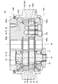
- Sectional drawing of the gear transmission of 1st Example is shown. About the gear transmission of 1st Example, the expanded sectional view of a main bearing is shown. Sectional drawing of the gear transmission of 2nd Example is shown.
- the contact angle between the spherical roller and the inner race may be 30 degrees or more and 60 degrees or less. If it is this range, both an axial load and a radial load can be borne in good balance.
- the “contact angle between the spherical roller and the inner race” means an angle formed by a surface orthogonal to the bearing center axis and a straight line indicating the direction of the force applied from the spherical roller to the inner race.
- the relative rotation speed of the case and the carrier may be 100 rpm or less. Since the temperature rise of the main bearing is suppressed, a large preload can be applied to the main bearing.
- the center of the circular arc of the spherical roller may be located outside the spherical roller. Since the size of the main bearing is reduced, a small gear transmission can be realized.
- FIG. 1 shows a cross-sectional view of the gear transmission 100.
- the gear transmission 100 is a type of reduction device that rotates eccentrically while the external gear 24 meshes with the internal gear 28.
- the gear transmission 100 uses the difference in the number of teeth between the external gear 24 and the internal gear 28 to increase the torque transmitted to the crankshaft 14 (decelerate the rotation) from the carrier 8. Output.
- the carrier 8 is rotated with respect to the case 38 using the difference in the number of teeth between the external gear 24 and the internal gear 28.
- the basic structure of the gear transmission 100 will be briefly described.
- the gear transmission 100 includes a case 38, a carrier 8, a crankshaft 14, and an external gear 24.
- the internal gear 28 includes a case 38 and a plurality of internal teeth pins 26 arranged on the inner periphery of the case 38.
- a pair of main bearings 2 (2X, 2Y) is disposed between the case 38 and the carrier 8.
- the carrier 8 is supported by the case 38 via the pair of main bearings 2.
- the carrier 8 is coaxial with the internal gear 28.
- the axis 36 is the axis of the carrier 8 and the internal gear 28.
- the pair of main bearings 2 are disposed outside the internal gear 28 in the direction of the axis 36. In other words, the internal gear 28 is disposed between the pair of main bearings 2 in the direction of the axis 36.
- the bearing central axis of the main bearing 2 is equal to the axis 36. Details of the main bearing 2 will be described later.
- a flange 38 a extending in the radial direction is formed on the inner peripheral surface of the case 38.
- “radial direction” means a direction perpendicular to the axis 36.
- the carrier 8 includes a first plate 8a and a second plate 8c.
- a columnar portion 8b extends from the first plate 8a toward the second plate 8c, and the columnar portion 8b and the second plate 8c are fixed.
- a first flange 8d extending in the radial direction is formed at the end of the first plate 8a.
- a second flange 8e extending in the radial direction is formed at the end of the second plate 8c.
- the oil seal 4 is disposed between the first plate 8a and the case 38. The oil seal 4 prevents the lubricant or the like injected into the gear transmission 100 from leaking out of the gear transmission 100.
- the carrier 8 supports the crankshaft 14 and the external gear 24.
- the crankshaft 14 is supported on the carrier 8 by a pair of bearings 12.
- the pair of bearings 12 are tapered roller bearings.
- the axis 34 of the crankshaft 14 is parallel to the axis 36. That is, the crankshaft 14 extends parallel to the axis 36 at a position offset from the axis 36.
- the crankshaft 14 includes an eccentric body 18 and an input gear 32.
- the eccentric body 18 is engaged with the external gear 24 via the cylindrical roller bearing 22.
- the external gear 24 is supported by the carrier 8 via the crankshaft 14.
- the columnar portion 8 b of the carrier 8 passes through the through hole 24 a of the external gear 24. A gap is secured between the inner wall of the through hole 24a and the columnar portion 8b.
- the crankshaft 14 rotates.
- the eccentric body 18 rotates eccentrically with respect to the axis 34 as the crankshaft 14 rotates.
- the external gear 24 rotates eccentrically while meshing with the internal gear 28.
- the number of teeth of the external gear 24 and the number of teeth of the internal gear 28 are different.
- the external gear 24 is supported by the carrier 8, and the internal gear 28 is formed on the inner peripheral surface of the case 38. Therefore, when the external gear 24 rotates eccentrically, the carrier 8 rotates relative to the case 38 according to the difference in the number of teeth between the external gear 24 and the internal gear 28.
- the relative rotational speed of the carrier 8 and the case 38 is adjusted to 100 rpm or less.
- the extension line of the rotary shaft 40X of the spherical roller of the main bearing 2X and the extension line of the rotary shaft 40Y of the spherical roller of the main bearing 2Y intersect between the main bearing 2X and the main bearing 2Y. More specifically, the extension line of the rotary shaft 40X and the extension line of the rotary shaft 40Y intersect at the midpoint of the main bearing 2X and the main bearing 2Y in the direction of the axis 36.
- the intersection of the rotary shaft 40X and the rotary shaft 40Y is located on the radially inner side of the main bearing 2 when observed from the direction of the axis 36.
- the main bearings 2X and 2Y may be arranged so that the intersection of the rotating shaft 40X and the rotating shaft 40Y is located on the radially outer side of the main bearing 2.
- FIG. 2 shows the main bearing 2 ⁇ / b> X disposed between the first plate 8 a and the case 38.
- the structure of the main bearing 2Y (see FIG. 1) is the same as the structure of the main bearing 2X. In the following description, only the main bearing 2X will be described, and description of the main bearing 2Y will be omitted.
- the main bearing 2 includes an outer race 56, an inner race 50, a spherical roller 54, and a retainer 52.
- a plurality of spherical rollers 54 are disposed between the outer race 56 and the inner race 50.
- the retainer 52 prevents the spherical rollers 54 from contacting each other.
- the retainer 52 is not in contact with the case 38 and the carrier 8. In other words, clearances are secured between the retainer 52 and the case 38 and between the retainer 52 and the carrier 8. The retainer 52 does not contact the case 38 and the carrier 8 even while the gear transmission 100 is driven.
- a circular arc-shaped depression is formed on the inner peripheral surface 56a of the outer race 56.
- An outer peripheral surface 56 b of the outer race 56 is fitted in the case 38.
- An end surface 56c of the outer race 56 in the direction of the bearing center axis 36 (see FIG. 1) is in contact with the flange 38a.
- On the outer peripheral surface 50b of the inner race 50 an arc-shaped depression is formed in a circle.
- An inner peripheral surface 50 a of the inner race 50 is fitted to the first plate 8 a of the carrier 8.
- An end surface 50c of the inner race 50 in the direction of the bearing center axis 36 is in contact with the first flange 8d of the first plate 8a.
- the curvatures of the rolling surface 54a of the spherical roller 54, the inner peripheral surface 56a of the outer race 56, and the outer peripheral surface 50b of the inner race 50 are substantially equal.
- the end surface of the inner race 50 in the bearing central axis 36 direction is in contact with the second flange 8e of the second plate 8c (see FIG. 1).
- a preload of 10 to 50% of the radial capacity (Cr) is applied to the main bearing 2.
- a preload of about 3 to 5% of the radial capacity (Cr) is applied to the bearing. That is, in the gear transmission 100, a large preload is applied as compared with a general method of using a bearing.
- the gear transmission 100 can apply a large preload to the main bearing, and can obtain high rigidity.
- a spacer may be disposed between the end face 50 c of the inner race 50 and the first flange 8 d of the carrier 8 to adjust the preload of the main bearing 2.
- the main bearing 2 includes the outer race 56 in which an arc-shaped depression is formed on the inner peripheral surface 56a, the inner race 50 in which an arc-shaped depression is formed on the outer peripheral surface 50b, and the spherical roller 54. It has. Therefore, in the case of the main bearing 2, the contact area between the rolling elements (spherical rollers) and the races (outer race and inner race) is wider than that of a conventional ball bearing (for example, an angular ball bearing). By using the main bearing 2, the durability of the gear transmission can be improved.
- a force that moves the spherical roller 54 to the outside of the gear transmission 100 along the rotation axis 40X (40Y) of the spherical roller 54 acts.
- the gear transmission 100 does not require a structure that restricts the movement of the rolling elements, unlike a conventional roller bearing (for example, an angular roller bearing).
- a conventional roller bearing for example, an angular roller bearing.
- the retainer 52 does not contact the case 38 and the carrier 8, the rotation of the spherical roller 54 is not hindered.
- the gear transmission 100 can achieve high durability with a simple structure as compared with the conventional gear transmission.
- the gear transmission 100 shows a broken line 6a indicating a surface orthogonal to the bearing center axis 36 and a broken line 6b indicating the direction of force applied from the spherical roller 54 to the inner race 50 (see also FIG. 2).
- the angle between the broken lines 6a and 6b that is, the contact angle Th between the spherical roller 54 and the inner race 50 is approximately 40 degrees.
- the contact angle Th between the spherical roller 54 and the inner race 50 is simply referred to as a contact angle Th.
- the contact angle Th is preferably adjusted between 30 degrees and 60 degrees.
- the contact angle Th is less than 30 degrees, the force applied in the axial direction cannot be sufficiently resisted, and the durability of the gear transmission decreases. Further, when the contact angle Th exceeds 60 degrees, the force applied in the radial direction cannot be sufficiently resisted, and the durability of the gear transmission decreases. When the contact angle Th is in the range of 30 degrees or more and 60 degrees or less, a gear transmission with excellent durability can be realized.
- the center 58 of the circular arc of the spherical roller 54 is located outside the spherical roller 54.
- the width of the spherical roller (the length in the direction perpendicular to the rotation axis) can be shortened.
- the small gear transmission 100 can be realized while maintaining the contact area between the spherical roller 52 and the race (the outer race 56 and the inner race 50).
- FIG. 3 shows a cross-sectional view of the gear transmission 200.
- the gear transmission 200 is a modification of the gear transmission 100, and the same components as the gear transmission 100 may be denoted by the same reference numerals or the same two lower digits, and the description thereof may be omitted.
- the crankshaft 214 is disposed coaxially with the internal gear 228. That is, the axis 234 of the crankshaft 214 coincides with the axis 236 of the internal gear 228.
- the crankshaft 214 is supported on the carrier 208 by a pair of bearings 212.
- the bearing 212 is a deep groove ball bearing.
- the eccentric body 218 of the crankshaft 214 is engaged with the external gear 224 via the cylindrical roller bearing 222.
- the columnar portion 208b of the carrier 208 passes through the through hole 224a of the external gear 224.
- the columnar portion 208b has a cylindrical shape.
- a cylindrical torque pin 230 is attached to the columnar portion 208b and is in contact with the inner wall of the through hole 224a.
- the columnar portion 208 b passes through the inside of the torque pin 230. Torque is transmitted from the external gear 224 to the carrier 208 at a contact point between the torque pin 230 and the inner wall of the through hole 224a.
- an arc-shaped depression 250 is formed around the carrier 208 in a round.
- the recess 250 of the carrier 208 also serves as an inner race of the main bearing 202. Therefore, the number of parts constituting the main bearing 202 is smaller than that of the gear transmission 100.
- This technique can also be applied to the gear transmission 100. That is, also in the gear transmission 100, the carrier 8 may be formed as a circular arc recess on the outer periphery of the carrier 8, and the carrier may be used as an inner race.
Landscapes
- Engineering & Computer Science (AREA)
- General Engineering & Computer Science (AREA)
- Mechanical Engineering (AREA)
- Retarders (AREA)
- Support Of The Bearing (AREA)
Applications Claiming Priority (2)
| Application Number | Priority Date | Filing Date | Title |
|---|---|---|---|
| JP2012009055A JP5875876B2 (ja) | 2012-01-19 | 2012-01-19 | 歯車伝動装置 |
| JP2012-009055 | 2012-01-19 |
Publications (1)
| Publication Number | Publication Date |
|---|---|
| WO2013108717A1 true WO2013108717A1 (fr) | 2013-07-25 |
Family
ID=48799143
Family Applications (1)
| Application Number | Title | Priority Date | Filing Date |
|---|---|---|---|
| PCT/JP2013/050431 Ceased WO2013108717A1 (fr) | 2012-01-19 | 2013-01-11 | Dispositif de transmission à engrenage |
Country Status (3)
| Country | Link |
|---|---|
| JP (1) | JP5875876B2 (fr) |
| TW (1) | TWI560379B (fr) |
| WO (1) | WO2013108717A1 (fr) |
Cited By (1)
| Publication number | Priority date | Publication date | Assignee | Title |
|---|---|---|---|---|
| CN107559388A (zh) * | 2016-06-30 | 2018-01-09 | 兄弟工业株式会社 | 减速器 |
Families Citing this family (2)
| Publication number | Priority date | Publication date | Assignee | Title |
|---|---|---|---|---|
| CN108884866B (zh) * | 2016-03-30 | 2020-08-25 | 谐波传动系统有限公司 | 组合式圆筒滚子轴承 |
| JP2025070606A (ja) * | 2023-10-20 | 2025-05-02 | 日本精工株式会社 | 減速機 |
Citations (3)
| Publication number | Priority date | Publication date | Assignee | Title |
|---|---|---|---|---|
| JP2003148478A (ja) * | 2001-11-13 | 2003-05-21 | Nsk Ltd | 転がり軸受 |
| JP2010519473A (ja) * | 2007-02-23 | 2010-06-03 | ヤコブ、ヴェルナー | ローラーベアリング |
| JP2010159774A (ja) * | 2009-01-06 | 2010-07-22 | Sumitomo Heavy Ind Ltd | 減速装置 |
Family Cites Families (3)
| Publication number | Priority date | Publication date | Assignee | Title |
|---|---|---|---|---|
| JP2002339985A (ja) * | 2001-05-11 | 2002-11-27 | Nsk Ltd | ころ軸受 |
| JP2007333048A (ja) * | 2006-06-14 | 2007-12-27 | Nsk Ltd | 軸受装置 |
| JP2009257481A (ja) * | 2008-04-17 | 2009-11-05 | Nsk Ltd | 車輪支持用軸受ユニット |
-
2012
- 2012-01-19 JP JP2012009055A patent/JP5875876B2/ja active Active
-
2013
- 2013-01-11 WO PCT/JP2013/050431 patent/WO2013108717A1/fr not_active Ceased
- 2013-01-17 TW TW102101805A patent/TWI560379B/zh active
Patent Citations (3)
| Publication number | Priority date | Publication date | Assignee | Title |
|---|---|---|---|---|
| JP2003148478A (ja) * | 2001-11-13 | 2003-05-21 | Nsk Ltd | 転がり軸受 |
| JP2010519473A (ja) * | 2007-02-23 | 2010-06-03 | ヤコブ、ヴェルナー | ローラーベアリング |
| JP2010159774A (ja) * | 2009-01-06 | 2010-07-22 | Sumitomo Heavy Ind Ltd | 減速装置 |
Cited By (1)
| Publication number | Priority date | Publication date | Assignee | Title |
|---|---|---|---|---|
| CN107559388A (zh) * | 2016-06-30 | 2018-01-09 | 兄弟工业株式会社 | 减速器 |
Also Published As
| Publication number | Publication date |
|---|---|
| TWI560379B (en) | 2016-12-01 |
| TW201333345A (zh) | 2013-08-16 |
| JP2013148161A (ja) | 2013-08-01 |
| JP5875876B2 (ja) | 2016-03-02 |
Similar Documents
| Publication | Publication Date | Title |
|---|---|---|
| US10161480B2 (en) | Eccentric oscillating speed reducer | |
| US8814737B2 (en) | Wheel driving device | |
| CN103608607A (zh) | 无级变速器 | |
| WO2012128003A1 (fr) | Décélérateur cycloïde et dispositif d'entraînement de moteur dans la roue | |
| JP6194241B2 (ja) | 歯車伝動装置 | |
| JP6285728B2 (ja) | 歯車伝動装置 | |
| CN104620020A (zh) | 齿轮传动装置和其使用的曲轴结构体 | |
| JP5875876B2 (ja) | 歯車伝動装置 | |
| JP5552359B2 (ja) | 減速装置 | |
| WO2018168763A1 (fr) | Engrenage de réduction différentielle | |
| EP2730805B1 (fr) | Engrenage réducteur | |
| JP5109515B2 (ja) | 摺動式トリポード形等速ジョイント | |
| TWI820817B (zh) | 共軛凸輪式減速機 | |
| JP6744244B2 (ja) | 差動減速機 | |
| JP6535447B2 (ja) | 歯車伝動装置 | |
| JP2015148242A (ja) | 車両用動力伝達装置 | |
| JP2013164167A (ja) | 歯車装置 | |
| JP2012013207A (ja) | トリポード型等速ジョイント | |
| JP5761445B2 (ja) | 無段変速機 | |
| JPWO2006112378A1 (ja) | 円筒ころ軸受 | |
| CN108351003A (zh) | 传动装置 | |
| JP6390187B2 (ja) | トロイダル型無段変速機 | |
| JP6561554B2 (ja) | トロイダル型無段変速機 | |
| JP6163119B2 (ja) | 車両用駆動力伝達装置 | |
| JP6015253B2 (ja) | トロイダル型無段変速機 |
Legal Events
| Date | Code | Title | Description |
|---|---|---|---|
| 121 | Ep: the epo has been informed by wipo that ep was designated in this application |
Ref document number: 13738401 Country of ref document: EP Kind code of ref document: A1 |
|
| NENP | Non-entry into the national phase |
Ref country code: DE |
|
| 122 | Ep: pct application non-entry in european phase |
Ref document number: 13738401 Country of ref document: EP Kind code of ref document: A1 |