WO2013108721A1 - Dispositif d'injection de carburant pour moteur à combustion interne - Google Patents
Dispositif d'injection de carburant pour moteur à combustion interne Download PDFInfo
- Publication number
- WO2013108721A1 WO2013108721A1 PCT/JP2013/050446 JP2013050446W WO2013108721A1 WO 2013108721 A1 WO2013108721 A1 WO 2013108721A1 JP 2013050446 W JP2013050446 W JP 2013050446W WO 2013108721 A1 WO2013108721 A1 WO 2013108721A1
- Authority
- WO
- WIPO (PCT)
- Prior art keywords
- fuel
- intake pipe
- fuel injection
- injection device
- pump unit
- Prior art date
- Legal status (The legal status is an assumption and is not a legal conclusion. Google has not performed a legal analysis and makes no representation as to the accuracy of the status listed.)
- Ceased
Links
Images


Classifications
-
- F—MECHANICAL ENGINEERING; LIGHTING; HEATING; WEAPONS; BLASTING
- F02—COMBUSTION ENGINES; HOT-GAS OR COMBUSTION-PRODUCT ENGINE PLANTS
- F02M—SUPPLYING COMBUSTION ENGINES IN GENERAL WITH COMBUSTIBLE MIXTURES OR CONSTITUENTS THEREOF
- F02M57/00—Fuel-injectors combined or associated with other devices
- F02M57/02—Injectors structurally combined with fuel-injection pumps
-
- F—MECHANICAL ENGINEERING; LIGHTING; HEATING; WEAPONS; BLASTING
- F02—COMBUSTION ENGINES; HOT-GAS OR COMBUSTION-PRODUCT ENGINE PLANTS
- F02M—SUPPLYING COMBUSTION ENGINES IN GENERAL WITH COMBUSTIBLE MIXTURES OR CONSTITUENTS THEREOF
- F02M59/00—Pumps specially adapted for fuel-injection and not provided for in groups F02M39/00 -F02M57/00, e.g. rotary cylinder-block type of pumps
- F02M59/12—Pumps specially adapted for fuel-injection and not provided for in groups F02M39/00 -F02M57/00, e.g. rotary cylinder-block type of pumps having other positive-displacement pumping elements, e.g. rotary
- F02M59/14—Pumps specially adapted for fuel-injection and not provided for in groups F02M39/00 -F02M57/00, e.g. rotary cylinder-block type of pumps having other positive-displacement pumping elements, e.g. rotary of elastic-wall type
-
- F—MECHANICAL ENGINEERING; LIGHTING; HEATING; WEAPONS; BLASTING
- F02—COMBUSTION ENGINES; HOT-GAS OR COMBUSTION-PRODUCT ENGINE PLANTS
- F02M—SUPPLYING COMBUSTION ENGINES IN GENERAL WITH COMBUSTIBLE MIXTURES OR CONSTITUENTS THEREOF
- F02M69/00—Low-pressure fuel-injection apparatus ; Apparatus with both continuous and intermittent injection; Apparatus injecting different types of fuel
- F02M69/02—Pumps peculiar thereto
-
- F—MECHANICAL ENGINEERING; LIGHTING; HEATING; WEAPONS; BLASTING
- F02—COMBUSTION ENGINES; HOT-GAS OR COMBUSTION-PRODUCT ENGINE PLANTS
- F02M—SUPPLYING COMBUSTION ENGINES IN GENERAL WITH COMBUSTIBLE MIXTURES OR CONSTITUENTS THEREOF
- F02M69/00—Low-pressure fuel-injection apparatus ; Apparatus with both continuous and intermittent injection; Apparatus injecting different types of fuel
- F02M69/46—Details, component parts or accessories not provided for in, or of interest apart from, the apparatus covered by groups F02M69/02 - F02M69/44
- F02M69/54—Arrangement of fuel pressure regulators
Definitions
- the present invention relates to a fuel injection device for an internal combustion engine in which fuel is pressurized and injected from an injector.
- a method of injecting fuel using an injector is widespread.
- this fuel injection device for injecting fuel a structure in which an intake pipe member constituting an intake pipe of an engine (corresponding to an internal combustion engine) is provided with a fuel pump for pressurizing fuel and an injector for injecting pressurized fuel is used. It is done.
- a reciprocating pump unit is used, and a structure in which the pump unit is driven by a driving unit such as a motor unit is used.
- a driving unit such as a motor unit.
- an integrated structure in which an injector, a fuel injection unit, a reciprocating pump unit, and a driving unit are connected has become widespread. I am doing.
- the engine of a motorcycle is housed in a limited space (engine room) surrounded by a fuel tank, a seat, a frame and the like.
- Engine accessories are also housed in this limited space.
- the fuel injection device attached to the engine is also housed in this limited space together with the engine accessories.
- the fuel injection device as much as possible around the intake pipe member, specifically, the intake pipe member so as not to interfere with surrounding equipment and objects, and so as not to affect the surrounding equipment.
- the compactness that suppresses projecting to the outside in the radial direction is required.
- the fuel injection device of Patent Document 1 is compact, the entire fuel pump, that is, the pump part and the motor part constituting the fuel pump are arranged in a biased manner on one radial side of the intake pipe member. Most of it protrudes from the one side in the radial direction of the intake pipe member. For this reason, this fuel injection device often interferes with surrounding equipment or objects or affects surrounding equipment, and tends to be difficult to mount on a motorcycle.
- a fuel injection device that uses an injector for the fuel injection portion and integrates the injector, the pump portion, and the drive portion further increases the overhang, making it more difficult to mount the fuel injection device on a motorcycle.
- An object of the present invention is to provide a fuel injection device for an internal combustion engine that is excellent in mountability in a vehicle and is prevented from protruding from the intake pipe member to the surroundings (radially outward).
- a fuel injection device is directed to a reciprocating pump type pump unit that pressurizes fuel at an outer peripheral part of an intake pipe member, and a pump part in a circumferential direction of the outer peripheral part.
- a fuel pump that is arranged along the reciprocating drive direction and a drive unit that drives the pump is arranged along the circumferential direction of the intake pipe member following the pump unit, and a fuel pump provided in the fuel pump And an injector for injecting the fuel from the inside into the intake pipe member.
- the pump part and the drive part of the fuel injection device are arranged along the circumferential direction of the intake pipe member.
- the reciprocating drive type pump unit is configured to have a plunger type pump unit, and the plunger type pump unit intersects the axial direction of the intake pipe member at the outer peripheral portion of the intake pipe member.
- the drive unit is configured to have a motor unit, and the motor unit is arranged along the circumferential direction of the outer periphery of the intake pipe member from the end of the plunger pump. It is arranged in a substantially L shape.
- the invention according to claim 3 is characterized in that the reciprocating pump unit and the drive unit are arranged closest to the outer periphery of the intake pipe member.
- the invention according to claim 4 is characterized in that the pump part and the drive part are arranged on a circular locus centering on the axis of the intake pipe member.
- the invention according to claim 5 is characterized in that the plunger type pump unit has a pressure regulator for keeping the discharged fuel at a predetermined pressure.
- the plunger type pump unit has a diaphragm type pump unit that assists the suction of the plunger type pump unit.
- the fuel injection device is compactly assembled to the outer peripheral portion of the intake pipe member with a layout in which each part including the injector is prevented from protruding to the surroundings, the devices around the intake pipe member Interference with objects and objects, and influences on the devices and objects are avoided, and mounting on vehicles is easy. Therefore, it is possible to provide a fuel injection device that is excellent in vehicle mountability and is prevented from protruding from the intake pipe member to the periphery (radially outward). In particular, this fuel injection device is effective for a vehicle such as a motorcycle, which is disposed in a considerably limited space (engine room).
- the vibration resistance in the fuel injection device using the plunger type pump unit which is difficult to ensure the weight balance with a simple structure, can be improved.
- the cylindrical plunger-type pump part has a center of gravity position close to the intake pipe member due to the crossing arrangement in the horizontal direction, and the pump part itself is hardly shaken, so that the overall vibration resistance of the fuel injection device is increased.
- the fuel injection device can suppress not only the overhang of each part but also the pump part and the motor part centered on the intake pipe member, and has high vibration resistance. It can be obtained together. According to the invention of claim 4, the fuel injection device can effectively improve the vibration resistance.
- the vehicle mountability is hardly changed.
- the vehicle mountability is hardly changed.
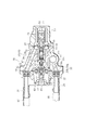
- FIG. 3 is a cross-sectional view taken along line AA in FIG. 2. Sectional drawing which shows the plunger type pump part, diaphragm type pump part, pressure regulator, and motor part (part) along the BB line in FIG.
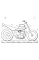
- FIG. 1 is a side view (schematic) of a vehicle, for example, a motorcycle, on which a fuel injection device to which the present invention is applied is installed.
- An arrow F in FIG. 1 indicates the front direction of the motorcycle, and an arrow R indicates the rear direction of the motorcycle.
- the motorcycle shown in FIG. 1 has a main frame member extending in the front-rear direction, for example, a main tube member 1 (only a part is shown).
- a front wheel 5 is suspended from a front end of the main tube member 1 via a front fork 3
- a rear wheel 9 is suspended from a rear end of the main tube member 1 via a swing arm member 7.
- the fuel tank 11 and the seat 12 are installed on the main tube member 1 in order from the front side.
- An acceleration / deceleration system (not shown) such as a brake pedal and a throttle grip is provided on one side (right side) sandwiching the main tube member 1, and a speed change system (not shown) such as a clutch lever and shift pedal is provided on the opposite side (left side). ) Is provided.
- an internal combustion engine for example, a reciprocating engine 13 in which a piston 13a is reciprocally mounted is installed.
- a short pipe member 15 (corresponding to the intake pipe member of the present application) and a throttle valve device 17 are sequentially connected to the intake side of the engine 13, and these include an intake side port (not shown) of the engine 13 and an air cleaner (not shown).
- An intake pipe that communicates with each other is configured.
- the short pipe member 15 is provided with each device constituting the fuel injection device 21, specifically, an electronically controlled injector 19, and a fuel pump 20 for supplying fuel to the injector 19.
- the injector 19, the fuel pump 20, Are integrally formed to constitute the fuel injection device 21.
- the fuel injection device 21 is installed using a limited space near the engine 13.
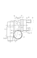
- the perspective view of FIG. 2 shows the entire structure and internal structure (dotted line portion) of the fuel injection device 21, and the exploded perspective view of FIG. 3 shows a main body that is the main part of the fuel injection device 21 for a motorcycle.
- 4 and 5 are cross-sectional views of the fuel injection device 21 (cross sections taken along lines AA and BB in FIG. 2). It is shown.
- the fuel injection device 21 will be described with reference to FIGS. 2 to 5.
- the fuel pump 20 includes a reciprocating pump unit 25 and a drive unit 27 that drives the pump unit 25 in series.
- the pump part 25 is comprised with the plunger-type pump part 35 which accommodated various pump components in the axial direction in the cylindrical pump main body 33, as FIG.2 and FIG.5 shows.
- the pump body 33 includes a body portion 33a and a lid portion 33b that are divided into two in the axial direction.
- the plunger-type pump unit 35 has a diaphragm-type pump unit 49 on one end side across the pump parts of the pump unit 35 and a pressure regulator 61 on the other end side, and is configured in a cylindrical shape (see FIG. 2). 5).
- the plunger-type pump unit 35 includes a cylindrical sleeve 37 incorporated along the axial direction of the pump body 33 with one end portion as a suction side and the other end portion as a discharge side.
- the plunger pump unit 35 guides the fuel (suction fuel) in the plunger 39 through the suction valve 41 to the pressurizing chamber 45 formed at the sleeve end. And the pressurized fuel is discharged from the discharge valve 43.
- the injector 19 is assembled to the pump main body 33 of the plunger pump unit 35 and constitutes the main body of the fuel injection device 21 together with the drive unit 27.
- the diaphragm pump 49 includes a diaphragm chamber 51 formed on the suction side of the sleeve 37, a diaphragm 53 provided so as to close the diaphragm chamber 51, and a central portion of the diaphragm 53 at the end of the plunger 39.
- a columnar fixing tool 55 to be fixed and a suction valve 57 communicating with the diaphragm chamber 51 through a passage 57a are provided.
- the diaphragm type pump unit 49 amplifies the diaphragm 51, and sucks fuel from the suction valve 57 and guides it into the plunger 39 by the pumping operation in the diaphragm chamber 51 caused by the amplitude.
- the diaphragm type pump unit 49 assists the insufficient suction function of the plunger type pump unit 35.
- the diaphragm chamber 51 also communicates with a return fuel discharge valve 59 through a passage 59a.
- the pressure regulator 61 has a structure in which the outlet of the discharge chamber 63 formed on the outlet side of the discharge valve 43 is closed by a diaphragm 67 with a relief valve 65, and the diaphragm 67 is pressed by a spring member 69.
- the pressure regulator 61 is attached to the diaphragm chamber 64 in which the fuel discharged from the discharge chamber 63 communicates with the discharge port 63, that is, the diaphragm chamber 64 partitioned by the diaphragm 67, according to the biasing force of the spring member 69. It has a structure in which the pressure is regulated to a predetermined pressure at the stage toward the force-side chamber 62.
- the pressure regulator 61 applies the same pressure to the opposite chamber partitioned by the diaphragm 67, that is, the spring chamber 71 containing the spring member 69 through the relief valve 65. It has a structure that allows fuel to escape.
- the discharge chamber 63 communicates with the injector 19 through a passage 19a and a connection port portion 33c (a portion where the base portion of the injector 19 is fitted) formed in the pump main body 33, which will be described later. 19 is provided.
- a cylindrical motor unit 27 a in which a DC motor 75 is housed in a cylindrical motor case 73 is used.
- a cam mechanism 77 conversion mechanism that converts rotational motion into reciprocating motion is built in the end of the motor case 73 where the output shaft of the DC motor 75 is disposed.
- the cam mechanism 77 is configured, for example, by assembling an eccentric cam 79 to the output shaft of the DC motor unit 75 and fitting a frame-shaped cam receiving member 81 to the eccentric cam 79. Converts eccentric rotational motion to reciprocating motion.
- the output portion of the cam receiving member 81 is disposed on the end portion of the motor case 73, here on the side portion perpendicular to the axial direction of the motor portion 27a.
- the pump unit 25 and the drive unit 27 are assembled on the outer periphery of the short tube member 15 so as not to protrude as far as possible to the outside in the radial direction of the short tube member 15 as a periphery.
- a structure in which the pump unit 25 and the drive unit 27 are arranged along the circumferential direction of the outer peripheral portion of the short tube member 15 is used.
- the plunger type pump unit 35 constituting the pump unit 25 intersects the axial direction of the short tube member 15 at the upper part of the outer peripheral portion of the short tube member 15. It is assembled sideways and is configured along the circumferential direction of the short tube member 15.
- the plunger-type pump unit 35 has a reciprocating drive direction of the pump unit 35 (a direction in which the plunger 39 is reciprocated), here an intermediate part in the axial direction of the plunger-type pump part 35 and the axial direction of the short tube member 15. Are crossed, for example, orthogonally crossed, along the outer peripheral portion of the short tube member 15.
- the motor unit 27 a constituting the driving unit 27 is arranged in an approximately L shape along the circumferential direction of the outer peripheral portion of the short tube member 15 from the end of the plunger type pump unit 35.
- the plunger type pump unit 35 is provided along the circumferential direction of the outer peripheral portion of the short tube member 15 following the plunger pump unit 35.
- the motor unit 27 a transmits the driving force from the motor unit 27 a to the plunger 39, the side of the motor case 73 having the output unit of the cam mechanism 75 is connected to the side of the pump main body 33 having the input unit of the plunger 39. It is configured to be connected to the end.
- the motor part 27 a is arranged along the downward direction, and the entire motor part 27 a is arranged along the outer peripheral part of the short tube member 25 in a vertical arrangement different from the plunger pump part 35.
- the plunger pump part 35 and the motor part 27a are both closest to the outer peripheral part of the short tube member 15.
- a suction connection port body 29 and a return connection port body 31 project from the end (the lid portion 33b) of the plunger pump unit 35 on the side opposite to the motor unit 27a of the plunger pump unit 35. Yes.
- the suction connection port body 29 communicates with the suction valve 57
- the return connection port body 31 communicates with the discharge valve 59.
- the suction connection port body 29 includes a fuel supply hose member 85 (only a part of which is shown by a two-dot chain line) extending from the lower portion of the fuel tank 11 and a stopper 86 such as a hose band (two in FIG. 4). And are connected by a dotted line). As a result, the fuel in the fuel tank 11 is guided to the suction connection port body 29.
- the return connection port 31 is configured by connecting a return hose member 87 (only a part of which is shown by a two-dot chain line) extending from the fuel tank 11 by a stopper 88 such as a hose band.
- a stopper 88 such as a hose band.
- the fuel injection device 21 is fixed to the short tube member 15 with a structure that stops the injector 19, the plunger pump unit 35, and the motor unit 27a.
- the injector 19 is fitted with a connection port 33c formed at the intermediate portion of the plunger-type pump portion 35 at the base portion, and the injection portion 19a at the tip portion is connected to the short tube member 15. It is supported so that it may fit in the support opening 15a (only one part is shown in FIG.2, 3) formed in the wall part.
- the plunger type pump part 35 is supported by connecting the middle part opposite to the injector 19, and the motor part 27 a is supported by suppressing the swing about the axis of the plunger type pump part 35 as a fulcrum. Yes.
- the plunger-type pump part 35 has a plate-like bracket part 95 protruding from the outer peripheral part of the intermediate part of the pump main body 33, a base-like mounting seat 98 provided on the outer peripheral part of the short tube member 15, and the bolt member 99.
- the bracket portion 95 is supported so as to be fastened to the mounting seat 98 by screwing.
- the motor portion 27a is provided with a pin portion 101 in parallel on the side portion of the motor portion 27a adjacent to the short tube member 15, for example, and a pin receiving seat 103 that receives the pin portion 101 on the outer peripheral portion of the short tube member 15 is provided.
- the pin unit 101 is supported by the short tube member 15 by a motor steadying structure in which the pin unit 101 is inserted into the pin hole 103a formed in the pin receiving seat 103 (FIG. 3). ).
- each part including the injector 19 of the fuel injection device 21 includes In addition, it does not protrude from the periphery (outside) of the short tube member 15 only in a specific direction. That is, as shown in FIGS. 2 and 4, the entire fuel injection device 21 can be compactly assembled to the outer peripheral portion of the short tube member 15 with a layout that suppresses overhanging as much as possible. .
- the fuel injection device 21 can be installed without interfering with or affecting the surrounding devices and objects. It is possible and easy to wear.
- the intermediate part of the plunger type pump part 35 is arranged on the short pipe member 15, the overhang is considerably suppressed.
- the fuel injection device 21 can be easily mounted in the engine room and has a considerably excellent vehicle mounting property.
- the fuel injection device 21 is effective for a vehicle such as a motorcycle in which the fuel injection device 21 is required to be disposed in a very limited small space near the engine 13.
- the reciprocating drive direction of the pump unit 35 is linearly along the circumferential direction of the short tube member 15, and this tangent line.
- the vehicle mountability includes a pressure regulator 61 that discharges fuel of an appropriate pressure and a diaphragm pump unit 37 that assists the suction of the plunger pump unit 35. But almost no change.
- the plunger-type pump unit 35 and the motor unit 27a are arranged closest to the outer periphery of the short tube member 15, respectively, and the rotational moment generated in the plunger-type pump unit 35 and the motor unit 27a with the short tube member 15 as the center. Therefore, even if the fuel injection device 21 as a whole is subjected to engine vibration or traveling vibration transmitted from the short tube member 15, it is difficult to shake, and the vibration resistance of the fuel injection device 21 itself is considerably improved.
- the plunger-type pump unit 35 and the motor unit 27 a are arranged on a circular locus closest to the outer peripheral portion of the short tube member 15 centering on the axis of the short tube member 15.
- the vibration of each part of the fuel injection device 21 around the short pipe member 15 is effectively suppressed, and the vibration resistance is effectively enhanced.
- the fuel injection device is provided in the short pipe member (the intake pipe member constituting the intake pipe) separate from the throttle valve apparatus. You may provide a pump part, a drive part, and an injector in the valve body (intake pipe member which comprises an intake pipe).
Landscapes
- Engineering & Computer Science (AREA)
- Chemical & Material Sciences (AREA)
- Combustion & Propulsion (AREA)
- Mechanical Engineering (AREA)
- General Engineering & Computer Science (AREA)
- Fuel-Injection Apparatus (AREA)
Priority Applications (4)
| Application Number | Priority Date | Filing Date | Title |
|---|---|---|---|
| BR112014017400A BR112014017400A8 (pt) | 2012-01-19 | 2013-01-11 | dispositivo de injeção de combustível para motor de combustão interna |
| IN5758DEN2014 IN2014DN05758A (fr) | 2012-01-19 | 2013-01-11 | |
| CN201380006093.2A CN104066967B (zh) | 2012-01-19 | 2013-01-11 | 内燃机的燃料喷射装置 |
| PH12014501645A PH12014501645B1 (en) | 2012-01-19 | 2014-07-17 | Fuel injection device for internal combustion engine |
Applications Claiming Priority (2)
| Application Number | Priority Date | Filing Date | Title |
|---|---|---|---|
| JP2012-008889 | 2012-01-19 | ||
| JP2012008889A JP5985190B2 (ja) | 2012-01-19 | 2012-01-19 | 内燃機関の燃料噴射装置 |
Publications (1)
| Publication Number | Publication Date |
|---|---|
| WO2013108721A1 true WO2013108721A1 (fr) | 2013-07-25 |
Family
ID=48799147
Family Applications (1)
| Application Number | Title | Priority Date | Filing Date |
|---|---|---|---|
| PCT/JP2013/050446 Ceased WO2013108721A1 (fr) | 2012-01-19 | 2013-01-11 | Dispositif d'injection de carburant pour moteur à combustion interne |
Country Status (7)
| Country | Link |
|---|---|
| JP (1) | JP5985190B2 (fr) |
| CN (1) | CN104066967B (fr) |
| BR (1) | BR112014017400A8 (fr) |
| IN (1) | IN2014DN05758A (fr) |
| MY (1) | MY167834A (fr) |
| PH (1) | PH12014501645B1 (fr) |
| WO (1) | WO2013108721A1 (fr) |
Cited By (1)
| Publication number | Priority date | Publication date | Assignee | Title |
|---|---|---|---|---|
| CN106536912A (zh) * | 2014-06-03 | 2017-03-22 | 株式会社三国 | 燃料泵的控制装置 |
Families Citing this family (2)
| Publication number | Priority date | Publication date | Assignee | Title |
|---|---|---|---|---|
| JP2015229931A (ja) * | 2014-06-03 | 2015-12-21 | 株式会社ミクニ | エンジンの始動制御装置 |
| JP6545006B2 (ja) * | 2015-06-08 | 2019-07-17 | 株式会社ミクニ | 燃料ポンプの制御装置及び制御方法 |
Citations (6)
| Publication number | Priority date | Publication date | Assignee | Title |
|---|---|---|---|---|
| JPH03117680A (ja) * | 1989-09-30 | 1991-05-20 | Yamaha Motor Co Ltd | 2サイクルエンジンの燃料供給装置 |
| JPH0454974U (fr) * | 1990-09-20 | 1992-05-12 | ||
| JP2003254187A (ja) * | 2002-02-28 | 2003-09-10 | Honda Motor Co Ltd | 車両の燃料ポンプモジュール |
| JP2005105987A (ja) * | 2003-09-30 | 2005-04-21 | Honda Motor Co Ltd | 内燃機関の燃料噴射装置 |
| JP2005133672A (ja) * | 2003-10-31 | 2005-05-26 | Keihin Corp | 車両の燃料供給装置 |
| JP2011012649A (ja) * | 2009-07-06 | 2011-01-20 | Aisan Industry Co Ltd | 燃料噴射装置 |
Family Cites Families (2)
| Publication number | Priority date | Publication date | Assignee | Title |
|---|---|---|---|---|
| JP4431268B2 (ja) * | 2000-11-17 | 2010-03-10 | 株式会社ミクニ | 電子制御燃料噴射装置 |
| CN201090340Y (zh) * | 2007-09-20 | 2008-07-23 | 高强 | 一体化电子燃油喷射装置 |
-
2012
- 2012-01-19 JP JP2012008889A patent/JP5985190B2/ja not_active Expired - Fee Related
-
2013
- 2013-01-11 MY MYPI2014701918A patent/MY167834A/en unknown
- 2013-01-11 BR BR112014017400A patent/BR112014017400A8/pt not_active IP Right Cessation
- 2013-01-11 WO PCT/JP2013/050446 patent/WO2013108721A1/fr not_active Ceased
- 2013-01-11 CN CN201380006093.2A patent/CN104066967B/zh not_active Expired - Fee Related
- 2013-01-11 IN IN5758DEN2014 patent/IN2014DN05758A/en unknown
-
2014
- 2014-07-17 PH PH12014501645A patent/PH12014501645B1/en unknown
Patent Citations (6)
| Publication number | Priority date | Publication date | Assignee | Title |
|---|---|---|---|---|
| JPH03117680A (ja) * | 1989-09-30 | 1991-05-20 | Yamaha Motor Co Ltd | 2サイクルエンジンの燃料供給装置 |
| JPH0454974U (fr) * | 1990-09-20 | 1992-05-12 | ||
| JP2003254187A (ja) * | 2002-02-28 | 2003-09-10 | Honda Motor Co Ltd | 車両の燃料ポンプモジュール |
| JP2005105987A (ja) * | 2003-09-30 | 2005-04-21 | Honda Motor Co Ltd | 内燃機関の燃料噴射装置 |
| JP2005133672A (ja) * | 2003-10-31 | 2005-05-26 | Keihin Corp | 車両の燃料供給装置 |
| JP2011012649A (ja) * | 2009-07-06 | 2011-01-20 | Aisan Industry Co Ltd | 燃料噴射装置 |
Cited By (2)
| Publication number | Priority date | Publication date | Assignee | Title |
|---|---|---|---|---|
| CN106536912A (zh) * | 2014-06-03 | 2017-03-22 | 株式会社三国 | 燃料泵的控制装置 |
| CN106536912B (zh) * | 2014-06-03 | 2019-11-26 | 株式会社三国 | 燃料泵的控制装置 |
Also Published As
| Publication number | Publication date |
|---|---|
| BR112014017400A8 (pt) | 2017-07-04 |
| MY167834A (en) | 2018-09-26 |
| JP5985190B2 (ja) | 2016-09-06 |
| BR112014017400A2 (pt) | 2017-06-13 |
| IN2014DN05758A (fr) | 2015-04-10 |
| CN104066967B (zh) | 2016-10-26 |
| CN104066967A (zh) | 2014-09-24 |
| PH12014501645A1 (en) | 2014-10-13 |
| JP2013148003A (ja) | 2013-08-01 |
| PH12014501645B1 (en) | 2014-10-13 |
Similar Documents
| Publication | Publication Date | Title |
|---|---|---|
| US8439146B2 (en) | Canister device for motorcycle | |
| JP5931856B2 (ja) | 高圧燃料ポンプ装置 | |
| JP2011163252A (ja) | エンジン | |
| JP6673994B2 (ja) | エンジン | |
| JP5965306B2 (ja) | トランスミッションの潤滑構造 | |
| JP2013113260A (ja) | 多連スロットル装置 | |
| JP5985190B2 (ja) | 内燃機関の燃料噴射装置 | |
| JP2013204517A (ja) | 可変流量オイルポンプを備えたエンジン | |
| JP2010281223A (ja) | 自動二輪車エンジンのオイルブリーザ装置 | |
| CN102285404B (zh) | 车辆的燃料供给装置 | |
| JP5968628B2 (ja) | 内燃機関の燃料供給装置 | |
| CN105143657B (zh) | 燃料泵的安装结构 | |
| JP2011252405A (ja) | 車両の燃料供給装置 | |
| JP2003049708A (ja) | 小型エンジン | |
| WO2003062627A1 (fr) | Dispositif d'alimentation en combustible | |
| KR101398856B1 (ko) | 농작업차용 디젤엔진 | |
| JP2013194605A (ja) | 鞍乗型車両の燃料供給構造 | |
| JP6072411B2 (ja) | 燃料圧力制御装置および同装置を用いた燃料供給装置 | |
| JP2012211552A (ja) | 自動二輪車の燃料供給装置 | |
| JP5921815B2 (ja) | 内燃機関の燃料ガス処理装置 | |
| JP2016188629A (ja) | 小型車両の燃料供給ポンプ配置構造 | |
| JP2020165345A (ja) | 高圧燃料ポンプ | |
| JPH04219410A (ja) | 小型艇用エンジンのオイルポンプ駆動装置 |
Legal Events
| Date | Code | Title | Description |
|---|---|---|---|
| 121 | Ep: the epo has been informed by wipo that ep was designated in this application |
Ref document number: 13738706 Country of ref document: EP Kind code of ref document: A1 |
|
| WWE | Wipo information: entry into national phase |
Ref document number: 12014501645 Country of ref document: PH |
|
| NENP | Non-entry into the national phase |
Ref country code: DE |
|
| REG | Reference to national code |
Ref country code: BR Ref legal event code: B01A Ref document number: 112014017400 Country of ref document: BR |
|
| 122 | Ep: pct application non-entry in european phase |
Ref document number: 13738706 Country of ref document: EP Kind code of ref document: A1 |
|
| ENP | Entry into the national phase |
Ref document number: 112014017400 Country of ref document: BR Kind code of ref document: A2 Effective date: 20140715 |