WO2013111190A1 - 表示システム、アタッチメントおよび表示装置 - Google Patents
表示システム、アタッチメントおよび表示装置 Download PDFInfo
- Publication number
- WO2013111190A1 WO2013111190A1 PCT/JP2012/000468 JP2012000468W WO2013111190A1 WO 2013111190 A1 WO2013111190 A1 WO 2013111190A1 JP 2012000468 W JP2012000468 W JP 2012000468W WO 2013111190 A1 WO2013111190 A1 WO 2013111190A1
- Authority
- WO
- WIPO (PCT)
- Prior art keywords
- attachment
- external terminal
- display device
- display
- connector
- Prior art date
- Legal status (The legal status is an assumption and is not a legal conclusion. Google has not performed a legal analysis and makes no representation as to the accuracy of the status listed.)
- Ceased
Links
Images







Classifications
-
- H—ELECTRICITY
- H04—ELECTRIC COMMUNICATION TECHNIQUE
- H04N—PICTORIAL COMMUNICATION, e.g. TELEVISION
- H04N5/00—Details of television systems
- H04N5/64—Constructional details of receivers, e.g. cabinets or dust covers
Definitions
- the present invention relates to a display system. More specifically, the present invention relates to a display system having a display device and an attachment, wherein the external system used for the display device is inserted into the attachment and used.
- Some conventional display devices which extend the function of the display device by connecting an external terminal.
- an external terminal connected to the display device, a card equipped with an IC for decrypting an encrypted broadcast signal, a recording medium, and a communication module can be cited.
- a slot for inserting an external terminal is mounted on the internal substrate.
- the slot for inserting the external terminal or the external terminal itself occupies the space on the substrate, and there is a problem that it is difficult to facilitate the design and cost reduction of the display device.
- the conventional technology assumes that most of the external terminals are stored in the display device. Therefore, it is necessary to secure a space (for example, a slot) for storing the external terminal on the substrate in the display device.
- an external terminal is basically a matter selected by the user. That is, even if a space for storing the external terminal is secured on the substrate, the external terminal may not be used at all. In such a case, the space for the external terminal on the board is wasted. If the space for the external terminal can be reduced from the substrate, the design can be facilitated and the cost can be reduced.
- the present invention has been made to solve the above problems, and an object of the present invention is to provide a display system in which a space for storing an external terminal is not provided on a substrate of a display device.
- the display system includes a display device, an external terminal, and an attachment for attaching the external terminal to the display device.
- the display device includes a display panel and a back cover that covers a back surface of the display panel, and is provided with a connector into which an attachment is inserted along a direction substantially parallel to the display surface of the display panel.
- the attachment is a first interface connected to the connector, a second interface connected to the external terminal, and a bridging portion that electrically connects the first interface and the second interface.
- the position of the first interface and the position of the second interface are arranged so that the external terminal is on a different surface from the back cover when the external terminal is attached to the display device via the attachment. And a bridging portion to be regulated.
- the first and second interfaces of the attachment are arranged along the direction substantially parallel to the display surface of the display panel and the connector and Each may be connected to an external terminal.
- the back cover may be provided with a step portion having a surface substantially perpendicular to the display surface of the display panel, and the connector may be provided on the surface.
- the surface may be substantially perpendicular to the vertical direction.
- the connector may open upward in the vertical direction.
- the surface may be provided near the outer edge of the back cover.
- the back cover may constitute at least one of an upper surface, a lower surface, and a side surface of the display device, and the connector may be provided on the at least one surface.
- the attachment may be U-shaped.
- the first interface may include a terminal inserted into the connector and at least one guide for determining a position where the terminal is inserted into the connector.
- An attachment according to the present invention is an attachment for attaching an external terminal to a display device, and the display device includes a display panel and a back cover provided with a connector, and the attachment includes the connector and the connector.
- a bridging portion that regulates the position of the first interface and the position of the second interface is provided so that the external terminal exists on a different surface from the back cover when attached to the display device.
- the display device is a display device to which an external terminal is connected via an attachment, and the attachment includes a first interface connected to the display device, and a second interface connected to the external terminal.
- a bridging portion for electrically connecting the first interface and the second interface, wherein the external terminal is different from the back cover when the external terminal is attached to the display device via the attachment.
- the display device includes a bridging portion that regulates the position of the first interface and the position of the second interface so as to exist on a surface, and the display device covers a display panel and a back cover of the display panel And the attachment of the attachment along a direction substantially parallel to the display surface of the display panel.
- Connector serial first interface is plugged in and a back cover provided.
- the attachment to which the external terminal is connected is connected to the back cover via the connector formed in the step portion of the back cover of the display device.
- an external terminal can be connected to the display device.
- FIG. 1 is a diagram showing a display system 10 in which an external terminal 204 is attached to a display device 100 via an attachment 203.
- FIG. 1 is an internal configuration diagram of a back surface of a display device 100 of a display system 10 according to Embodiment 1.
- FIG. 3 is a partially enlarged view of a connector 205. It is an enlarged view of the attachment 203 concerning Embodiment 1.
- FIG. It is sectional drawing of the attachment 203 in an AA line (FIG. 6). 3 is a cross-sectional view showing a positional relationship between an attachment 203 and a display device 100 immediately before being mounted.
- FIG. 1 is a diagram showing a display system 10 in which an external terminal 204 is attached to a display device 100 via an attachment 203.
- FIG. 1 is an internal configuration diagram of a back surface of a display device 100 of a display system 10 according to Embodiment 1.
- FIG. 3 is a partially enlarged view of a connector 205. It is an enlarged
- FIG. 6 is a cross-sectional view showing a positional relationship between the attachment 203 and the display device 100 when the attachment 203 is fixed to the connector 205.
- FIG. FIG. 6 is a rear view of a display device 110 according to a second embodiment. It is a figure which shows the display apparatus 110 with which the attachment 203 by which the external apparatus 204 was inserted in the connector 205 was attached. It is sectional drawing of the display apparatus 110 in the BB line (FIG. 9). It is sectional drawing which shows the positional relationship of the attachment 203 and the display apparatus 110 just before mounting
- FIG. 6 is a cross-sectional view showing the positional relationship between the attachment 203 and the display device 110 when the insertion part 301 of the attachment 203 is inserted into the connector 205. It is a figure which shows the example in which the connector 205 was provided on the back cover 201 which comprises a display apparatus upper surface.
- the display system has a display device, an external terminal, and an attachment for connecting the display device and the external terminal.
- a space for incorporating an external terminal is not provided in the display device.
- a connector into which an attachment is inserted is provided on the back cover.
- the external terminal is attached to the display device 100 via an attachment.
- the connector on the display device side for attaching the attachment is located at a position where the user can easily attach the attachment, for example, a step provided on the back cover, or when the back cover is attached to the display device. It is provided at any position on the top, bottom and side surfaces of the display device.
- the attachment in a substantially U shape, the user can easily and surely attach the attachment to the display device so as to be hooked.
- FIG. 1 is a front view of a display device 100 according to the present embodiment.
- the display device 100 includes a display panel 101 and a front panel 102.
- the display device 100 converts a broadcast signal or data recorded on an external recording medium into a video signal and displays it.
- Examples of the display device 100 include a television receiver and a general-purpose display.
- the display panel 101 displays a video corresponding to the video signal.
- the display panel 101 can be composed of a plasma display panel, a liquid crystal panel, an organic EL panel, or the like.
- the front panel 102 is a frame that holds the display panel 101. Resin or metal is used as the material of the front panel 102.
- FIG. 2 is a rear view of the display device 100.
- the display device 100 includes a back cover 201.
- the back cover 201 covers the back surface of the display panel 101.
- the back cover 201 is coupled to the front panel 102 and holds the display panel 101. Resin or metal is used as the material of the back cover 201.
- the back cover 201 is provided with a stepped portion 202.
- the stepped portion 202 rises in a direction substantially perpendicular to the vertical direction.
- the stepped portion 202 rises in a substantially vertical direction from the main plane constituting the back cover 201.
- the “main plane” here means a plane constituted by four sides of the back cover 201 on the drawing.
- the shape of the illustrated back cover 201 is merely an example, and various shapes such as a curved shape are conceivable, so the “main plane” may not be clearly defined.
- the display surface of the display panel 101 is generally a flat surface as shown in FIG. Therefore, in this specification, the position of the stepped portion 202 or the like may be specified in relation to the display panel 101.
- the stepped portion 202 protrudes in a direction substantially perpendicular to the display surface of the display panel 101 or on the back side when the display panel 101 is the front surface.
- a connector 205 to which the attachment 203 is connected is disposed on the step portion 202 of the back cover 201.
- the attachment 203 is inserted into the connector 205 along a direction substantially parallel to the display surface of the display panel 101.
- An external terminal 204 is attached to the attachment 203.
- Two guide holes 206 are provided in the vicinity of the connector 205. Insertion guides for attachments 203 to be described later are inserted into the two guide holes 206.
- the external terminal 204 has a card shape conforming to the PCMCIA standard.
- the external terminal 204 is a CI module (CI card) related to digital television broadcasting in Europe, for example.
- the external terminal 204 has a function of releasing the encryption applied to the broadcast signal received by the display device 100. Details will be described later.
- FIG. 2 shows the attachment 203 to which the external terminal 204 is attached.
- the display device 100, the external terminal 204, and the attachment 203 for attaching the external terminal 204 to the display device 100 may be collectively referred to as the display system 10.
- the back cover 201 only needs to constitute at least a part of the back surface of the display device 100 and have a configuration to which the attachment 203 can be connected. Other configurations are not particularly limited.
- the back cover 201 is not necessarily combined with the front panel 102.
- the stepped portion 202 protrudes from the back side as viewed from the display panel 101.
- the stepped portion 202 is formed of the same member as the back cover 201.
- the stepped portion 202 only needs to protrude from the main plane of the back cover 201, and other configurations are not particularly limited.
- the back cover 201 itself may be flat, and a cover including the stepped portion 202 may be connected from above.
- the attachment 203 is connected to a connector provided in the step portion 202.
- FIG. 3 shows the display system 10 in which the external terminal 204 is attached to the display device 100 via the attachment 203.
- the attachment 203 is inserted into the connector 205 (FIG. 2) disposed in the stepped portion 202 of the back cover 201 along a direction substantially parallel to the display surface of the display panel 101. A more detailed description will be given later.
- FIG. 4 is an internal configuration diagram of the back surface of the display device 100 of the display system 10 according to the present embodiment.
- FIG. 4 shows the back of the display device 100 with the back cover 201 removed.
- a substrate 401 is provided inside the back surface of the display device 100.
- a connector 205 is mounted on the substrate 401.
- An electric circuit for processing an electric signal from the connector 205 is further mounted on the substrate 402.
- a space for providing the external terminal 204 is not provided on the substrate 401. Only such a connector 205 for external equipment is provided without providing such a space. As a result, the size of the substrate 401 can be reduced.
- FIG. 5 is a partially enlarged view of the connector 205.
- the connector 205 is positioned so as to appear at the stepped portion 202 through an opening provided in the back cover 201.
- FIG. 6 is an enlarged view of the attachment 203 according to the present embodiment.
- the attachment 203 includes an insertion portion 301 that is a first interface, an external terminal slot 302 that is a second interface, an insertion guide 303, and a bridging portion 304.
- the insertion part 301 is inserted into the connector 205.
- the insertion part 301 is comprised from the several insertion member.
- the display device 100 and the attachment 203 are fixed by inserting the insertion portion 301 into the slot of the outer periphery 202.
- External terminal 204 is inserted into external terminal slot 302.
- the attachment 203 and the external terminal 204 are fixed.
- the external terminal 204 can be electrically connected to the insertion unit 301. In this way, the external terminal 204 is connected to the display device 100 in a circuit. That is, the display device 100 can use the function of the external terminal 204.
- the orientation of the external terminal slot 302 when the attachment 203 is fixed to the display device 100 is defined so that the external terminal 204 inserted into the external terminal slot 302 is parallel to the plug-in portion 301.
- the insertion guide 303 functions as a guide when the insertion part 301 is inserted into the connector 205.
- the insertion guide 303 is inserted into a guide hole 206 (FIG. 2) disposed in the vicinity of the connector 205.
- the insertion part 301 has a function which maintains a connection so that the insertion part 301 and the connector 205 may not remove
- each of the insertion guides 303 is positioned so as to contact the outer periphery of the connector 205.
- the connector 205 is sandwiched between the insertion portion 301 and the insertion guide 303, and the insertion portion 301 and the connector 205 are unlikely to come off.
- the insertion guide 303 is installed in parallel with the direction in which the substrate 401 (FIG. 4) constituting the electronic device spreads. Thereby, the influence with respect to the thickness of the housing
- Various configurations of the insertion guide 303 are conceivable, but if the configuration shown in FIG. 6 is adopted, the display device 100 can also be made thinner.
- the insertion guide 303 in the present embodiment has a structure capable of protecting the insertion portion 301.
- the insertion guide 303 is configured to be longer than the insertion part 301.
- the insertion guide 303 is disposed outward from the insertion portion 301.
- the “outward direction” means a direction opposite to the external terminal slot 302 on the bridging portion 304.
- insertion guides 303 there are two insertion guides 303, but the number is arbitrary. It is sufficient that at least one exists. However, it is not essential to provide an insertion guide.
- the bridging part 304 physically connects the insertion part 301 and the insertion guide 303 to the external terminal slot 302.
- the bridging portion 304 also electrically connects the insertion portion 301 and the external terminal slot 302.
- the cross section of the attachment 203 is substantially U-shaped.
- FIG. 7 is a cross-sectional view of the attachment 203 taken along line AA (FIG. 6).
- the external terminal 204 inserted into the external terminal slot 302 is also shown in the figure.
- the external terminal 204 is connected to the terminal group 701 of the attachment 203 and is electrically connected to the plug-in part 301 via the wiring 702 in the bridging part 304.
- FIG. 8A is a cross-sectional view showing a positional relationship between the attachment 203 and the display device 100 immediately before being mounted.
- the user moves the attachment 203 to which the external terminal 204 is fixed along the back cover 201 or the display panel 101 in the direction of the connector 205. Then, the insertion part 301 is inserted into the connector 205. At the time of insertion and fixing, the attachment 203 can be fixed to the connector 205 while further sliding part of the external terminal 204 and the attachment 203 on the back cover 201.
- the external terminal 204 and the back cover 201 are arranged in a close proximity.
- the external terminal 204 and the back cover 201 are not arranged on the same surface but are on different surfaces. This is because the bridging portion 304 has a substantially U shape and restricts (shifts) the positions of the insertion portion 301 and the external terminal slot 302. Electrical connection will be ensured. Thereby, it is possible to control the external terminal 204 from the display device 100.
- FIG. 9 is a rear view of the display device 110 according to the present embodiment.
- Constituent elements corresponding to the constituent elements of the display device 100 of Embodiment 1 are denoted by the same reference numerals and are referred to by the same names.
- Embodiment 1 it has been described that a part of the back cover 201 protrudes toward the back side when the display panel is the front side.
- the back cover 201 of the display device 110 is provided with a recess 90.
- a plurality of surfaces substantially perpendicular to the display panel that form the recesses 90 correspond to the stepped portion 202 according to the first embodiment.
- the connector 205 is provided at the stepped portion 202.
- FIG. 10 shows the display device 110 in which an attachment 203 into which an external device 204 is inserted is attached to the connector 205.
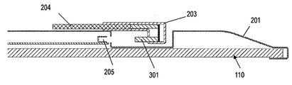
- FIG. 11A is a cross-sectional view of the display device 110 taken along the line BB (FIG. 9). It will be understood that the connector 205 is provided in the stepped portion 202.
- FIG. 11B is a cross-sectional view showing the positional relationship between the attachment 203 and the display device 110 immediately before being mounted.
- the user puts the side of the attachment 203 on which the external terminal 204 is fixed to the insertion portion 301 into the concave portion 90 and moves it in the direction of the connector 205 along the back cover 201 or the display panel 101 as it is. Then, the insertion part 301 is inserted into the connector 205. At the time of insertion and fixing, the attachment 203 can be fixed to the connector 205 while further sliding part of the external terminal 204 and the attachment 203 on the back cover 201.
- FIG. 11C is a cross-sectional view showing a positional relationship between the attachment 203 and the display device 110 when the insertion portion 301 of the attachment 203 is inserted into the connector 205.
- the external terminal 204 and the back cover 201 are arranged in close proximity to ensure electrical connection. As a result, the external terminal 204 can be controlled from the display device 110.
- the fact that the external terminal 204 and the back cover 201 are on different surfaces and the reason are as described in the first embodiment.
- the display device 100 is not provided with a space for incorporating an external terminal. Therefore, the space for the external terminal can be reduced from the substrate. As a result, simplification of design and realization of cost reduction can be promoted.
- the stepped portion on the back surface of the display device 110 may be provided near the outer edge of the back cover, and the connector may be provided on the stepped portion.
- the direction in which the load is applied is not limited to the vertically downward direction.
- the structure which applies a load from a horizontal direction or a downward direction may be sufficient.
- the connector is provided in the stepped portion or the recessed portion on the rear surface of the display device, but this is an example.
- FIG. 12 shows an example in which a connector 205 is provided on a back cover 201 constituting the upper surface of the display device.
- the connector 205 opens upward in the vertical direction.
- a display panel 101 and a front panel 102 are also shown.
- the back cover 201 is not provided with a step portion or a recess.
- the position where the connector 205 is provided is not limited to the upper surface of the display device.
- the connector 205 may be provided on at least one of the upper surface, the lower surface, and the side surface.
- the display system of the present invention is useful as a system formed by an external terminal and a display device for releasing viewing restrictions.
Landscapes
- Engineering & Computer Science (AREA)
- Multimedia (AREA)
- Signal Processing (AREA)
- Devices For Indicating Variable Information By Combining Individual Elements (AREA)
Abstract
外部端末を収納するスペースを基板上に設けない表示システムを提供する。 表示システムは、表示装置、外部端末、および外部端末を表示装置に取り付けるためのアタッチメントを有している。表示装置は、表示パネルと、表示パネルの裏面を覆うバックカバーであって、表示パネルの表示面と略平行な方向に沿ってアタッチメントが差し込まれるコネクタが設けられたバックカバーとを備えている。アタッチメントは、コネクタと接続される第1インターフェースと、外部端末と接続される第2インターフェースと、第1インターフェースおよび第2インターフェースを電気的に接続する架橋部であって、外部端末がアタッチメントを介して表示装置に取り付けられたときに、外部端末がバックカバーと異なる面上に存在するよう、第1インターフェースの位置および第2インターフェースの位置を規制する架橋部とを備えている。
Description
本発明は表示システムに関する。より詳しくは、表示装置とアタッチメントとを有する表示システムであって、表示装置の用に供する外部端末をアタッチメントに挿入して使用する表示システムに関する。
従来の表示装置の中には、外部端末を接続することにより、その表示装置の機能を拡張するものが知られている。表示装置に接続される外部端末の一例としては、暗号化された放送信号を復号するICを搭載したカードや、記録媒体や、通信モジュールが挙げられる。
たとえば特許文献1に記載された表示装置では、その内部基板上に外部端末を挿入するスロットが実装されている。
従来の技術では、外部端末を挿入するスロットまたは外部端末そのものが基板上のスペースを占有してしまい、表示装置の設計の容易化やコストダウンが難しいという課題があった。
より具体的に説明すると、従来の技術では外部端末の大部分が表示装置内に収納されることを前提としている。そのため、表示装置内の基板上には外部端末を収納するスペース(たとえばスロット)を確保することが必要であった。
しかしながら、外部端末を使用するか否かは基本的には使用者が選択する事項である。つまり、外部端末を収納するスペースを基板上に確保していたとしても、外部端末が一切使用されない場合もある。このような場合には、基板上の外部端末のためのスペースは無駄となる。仮に、基板上から外部端末のためのスペースを削減することができれば、設計の容易化やコストダウンにつながる。
本発明は上記課題を解決するためになされたものであって、その目的は、外部端末を収納するスペースを表示装置の基板上に設けない表示システムを提供することにある。
表示システムは、表示装置、外部端末、および前記外部端末を前記表示装置に取り付けるためのアタッチメントを有する。前記表示装置は、表示パネルと、前記表示パネルの裏面を覆うバックカバーであって、前記表示パネルの表示面と略平行な方向に沿ってアタッチメントが差し込まれるコネクタが設けられたバックカバーとを備えており、前記アタッチメントは、前記コネクタと接続される第1インターフェースと、前記外部端末と接続される第2インターフェースと、前記第1インターフェースおよび前記第2インターフェースを電気的に接続する架橋部であって、前記外部端末が前記アタッチメントを介して前記表示装置に取り付けられたときに、前記外部端末が前記バックカバーと異なる面上に存在するよう、前記第1インターフェースの位置および前記第2インターフェースの位置を規制する架橋部とを備えている。
前記外部端末が前記アタッチメントを介して前記表示装置に取り付けられたときにおいて、前記アタッチメントの前記第1および第2インターフェースは、前記表示パネルの表示面と略平行な方向に沿って、前記コネクタおよび前記外部端末にそれぞれ接続されていてもよい。
前記バックカバーには、前記表示パネルの表示面に略垂直な面を有する段差部が設けられており、前記コネクタは前記面に設けられていてもよい。
前記面はさらに鉛直方向に略垂直であってもよい。
前記コネクタは、鉛直方向上向きに開口していてもよい。
前記面は前記バックカバーの外縁近傍に設けられていてもよい。
前記バックカバーは、前記表示装置の上面、下面および側面の少なくとも1つの面を構成しており、前記コネクタは前記少なくとも1つの面に設けられていてもよい。
前記アタッチメントはU字形状であってもよい。
前記第1インターフェースは、前記コネクタに差し込まれる端子と、前記端子を前記コネクタに差し込む位置を決めるための少なくとも1つのガイドとを有していてもよい。
本発明によるアタッチメントは、外部端末を表示装置に取り付けるためのアタッチメントであって、前記表示装置は、表示パネルと、コネクタが設けられたバックカバーとを有しており、前記アタッチメントは、前記コネクタと接続される第1インターフェースと、前記外部端末と接続される第2インターフェースと、前記第1インターフェースおよび前記第2インターフェースを電気的に接続する架橋部であって、前記外部端末が前記アタッチメントを介して前記表示装置に取り付けられたときに、前記外部端末が前記バックカバーと異なる面上に存在するよう、前記第1インターフェースの位置および前記第2インターフェースの位置を規制する架橋部とを備えている。
本発明による表示装置は、アタッチメントを介して外部端末が接続される表示装置であって、前記アタッチメントは、前記表示装置と接続される第1インターフェースと、前記外部端末と接続される第2インターフェースと、前記第1インターフェースおよび前記第2インターフェースを電気的に接続する架橋部であって、前記外部端末が前記アタッチメントを介して前記表示装置に取り付けられたときに、前記外部端末が前記バックカバーと異なる面上に存在するよう、前記第1インターフェースの位置および前記第2インターフェースの位置を規制する架橋部とを有しており、前記表示装置は、表示パネルと、前記表示パネルの裏面を覆うバックカバーであって、前記表示パネルの表示面と略平行な方向に沿って前記アタッチメントの前記第1インターフェースが差し込まれるコネクタが設けられたバックカバーとを備えている。
本発明の表示システムによれば、表示装置のバックカバーの段差部に形成されたコネクタを介して、外部端末が接続されるアタッチメントをバックカバーに接続する。これにより、表示装置に外部端末を接続することができる。このような作用によって、表示装置側にコネクタの実装面積を設ければ、外部端子の接続が可能になり、設計の容易化やコストダウンが可能になる。
以下、添付の図面を参照しながら、本発明による表示システム、表示装置、外部端末およびアタッチメントの実施形態を説明する。
(実施の形態1)
まず、図1から図8Bを参照しながら、本実施形態にかかる表示システムの構成を説明する。
まず、図1から図8Bを参照しながら、本実施形態にかかる表示システムの構成を説明する。
表示システムは、表示装置、外部端末、および、表示装置と外部端末とを接続するアタッチメントを有している。本実施形態においては、外部端末を内蔵させるためのスペースを表示装置には設けていない。一方、外部端末を利用することを望む使用者のために、アタッチメントが差し込まれるコネクタをバックカバーに設けている。
本実施形態においては、外部端末はアタッチメントを介して表示装置100に装着される。アタッチメントを装着するための表示装置側のコネクタは、使用者がアタッチメントの装着を容易にすることができる位置、たとえばバックカバーに設けられた段差部や、バックカバーが表示装置に取り付けられたときにおける表示装置の上面、下面、側面のいずれかの位置に設けられている。
また、アタッチメントを略U字形状に構成することにより、使用者は引っかけるように容易かつ確実にアタッチメントを表示装置に装着することが可能になる。
図1は本実施形態にかかる表示装置100の正面図である。
表示装置100は表示パネル101とフロントパネル102を有する。
表示装置100は放送信号や外部記録媒体に記録されたデータを映像信号に変換して表示する。表示装置100の一例として、テレビジョン受信機や汎用ディスプレイが挙げられる。
表示パネル101は映像信号に対応した映像を表示する。表示パネル101は、具体的にはプラズマディスプレイパネルや、液晶パネル、有機ELパネルなどで構成可能である。
フロントパネル102は表示パネル101を保持する枠である。フロントパネル102の材料として樹脂あるいは金属が用いられる。
図2は表示装置100の背面図である。表示装置100はバックカバー201を有する。
バックカバー201は表示パネル101の裏面を覆っている。バックカバー201はフロントパネル102と結合されて表示パネル101を保持する。バックカバー201の材質として樹脂あるいは金属が用いられる。
バックカバー201には、段差部202が設けられている。図示されている矢印の方向を鉛直下向きとしたとき、段差部202は、鉛直方向に略垂直な方向に立ち上がっている。または、段差部202は、バックカバー201を構成する主平面から略垂直な方向に立ち上がっていると言うこともできる。ここでいう「主平面」とは、図面上のバックカバー201の四辺によって構成されている平面を意図している。
なお、図示されたバックカバー201の形状は一例であり、湾曲する等、種々の形状が考えられるため、「主平面」が明確に定義できない可能性がある。一方、表示パネル101の表示面は図1に示されるように平面であることが一般的である。そこで、本明細書では、表示パネル101との関係で段差部202等の位置を特定することもある。たとえば段差部202は、表示パネル101の表示面に略垂直な方向、または表示パネル101を前面としたとすると背面奥側に突出している。
バックカバー201の段差部202には、アタッチメント203が接続されるコネクタ205が配置されている。アタッチメント203は、表示パネル101の表示面と略平行な方向に沿ってコネクタ205に差し込まれる。アタッチメント203には、外部端末204が取り付けられる。なお、コネクタ205に近接して、2つのガイド孔206が設けられている。2つのガイド孔206には、後述するアタッチメント203の挿入ガイドが差し込まれる。
本実施形態においては、外部端末204はPCMCIA規格に適合したカード形状をしているとしている。外部端末204は、たとえば欧州におけるデジタルテレビ放送に関するCIモジュール(CIカード)である。
外部端末204は表示装置100が受信する放送信号に施された暗号を解除する機能を有する。詳細は後述する。
図2には、外部端末204が取り付けられたアタッチメント203が示されている。本実施形態では、表示装置100、外部端末204、および外部端末204を表示装置100に取り付けるためのアタッチメント203を総合して、表示システム10と呼ぶこともある。
バックカバー201は表示装置100の少なくとも一部の背面を構成し、かつアタッチメント203が接続可能な構成を有するものであればよい。その他の構成は特に限定されない。例えばバックカバー201は、フロントパネル102と結合される必要は必ずしも無い。
段差部202は表示パネル101から見て背面奥側に突出している。本実施の形態において、段差部202はバックカバー201と同一部材で形成されている。しかし、段差部202はバックカバー201の主平面から突出していればよく、その他の構成は特に限定されない。例えば、バックカバー201自体は平坦であって、その上から段差部202を含むカバーを接続してもよい。
アタッチメント203は段差部202に設けられたコネクタに接続される。
図3は、外部端末204がアタッチメント203を介して表示装置100に取り付けられた表示システム10を示す。上述のように、アタッチメント203はバックカバー201の段差部202に配置されているコネクタ205(図2)に、表示パネル101の表示面と略平行な方向に沿って差し込まれている。より詳しい説明は後述する。
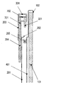
図4は本実施形態による表示システム10の表示装置100背面の内部構成図である。図4は、バックカバー201が取り外された表示装置100の背面を示している。表示装置100の背面内部には、基板401が設けられている。そして基板401上にはコネクタ205が実装されている。基板402にはコネクタ205からの電気信号を処理する電気回路がさらに実装されている。
図示されるように、基板401上には、外部端末204を設けるためのスペースは設けられていない。そのようなスペースを設けず、外部機器用のコネクタ205のみを設けている。これにより、基板401の大きさの縮小に貢献できる。
図5は、コネクタ205の部分拡大図である。バックカバー201が表示装置100に取り付けられたとき、コネクタ205は、バックカバー201に設けられた開口を通して段差部202に現れるよう位置決めされている。
図6は、本実施形態にかかるアタッチメント203の拡大図である。
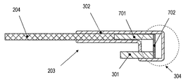
アタッチメント203は、第1のインターフェースである差込部301と、第2のインターフェースである外部端末スロット302と、挿入ガイド303と、架橋部304とを備えている。
差込部301はコネクタ205に挿入される。差込部301は複数の差込部材から構成されている。差込部301が外周202のスロットに挿入されることによって、表示装置100とアタッチメント203とが固定される。
外部端末スロット302には、外部端末204が差し込まれる。外部端末スロット302に外部端末204が差し込まれることによってアタッチメント203と外部端末204とが固定される。外部端末204の一部は外部端末スロット302と接続された際に差込部301と電気的に導通可能な状態となる。このようにして外部端末204は表示装置100と回路的に接続される。すなわち外部端末204の機能を表示装置100が利用可能となる。
アタッチメント203が表示装置100に固定された際の外部端末スロット302の向きは、外部端末スロット302に差し込まれる外部端末204が差込部301と平行となるように規定されている。
挿入ガイド303は、差込部301をコネクタ205に差し込む際のガイドとして機能する。本実施形態では、挿入ガイド303はコネクタ205の近傍に配置されたガイド孔206(図2)に差し込まれる。また、差込部301がコネクタ205に差し込まれた後は、差込部301とコネクタ205とが外れないよう、接続を維持する機能を有する。たとえば、差込部301がコネクタ205に挿入されたとき、挿入ガイド303の各々がコネクタ205の外周と接触するよう位置決めされている。これにより、差込部301と挿入ガイド303とによってコネクタ205を挟み込むことになり、差込部301とコネクタ205とが外れにくくなる。
挿入ガイド303は、電子機器を構成する基板401(図4)が広がる方向と平行に設置されている。これにより、表示装置100の筐体の厚さに対する影響が最小限に抑えられる。挿入ガイド303の構成は種々考えられるが、図6に示す構成を採用すれば、表示装置100の薄型化にも貢献できる。
更に本実施形態における挿入ガイド303は、差込部301を保護することが可能な構造を有している。たとえば、挿入ガイド303は差込部301よりも長くなるよう構成されている。または、挿入ガイド303は差込部301よりも外方向に配置されている。ここでいう「外方向」とは、架橋部304上において、外部端末スロット302とは反対の方向を意味する。上述のいずれかのように挿入ガイド303の形状または形成位置を調整することにより、操作の誤りにより、使用者がアタッチメント203を他の物体に接触させ、または落下させたとしても、挿入ガイド303が先に当該他の物体や床に接触する。これにより、繊細な構造を有する差込部301を保護することができる。
なお、本実施形態では挿入ガイド303は2つ存在しているが、数は任意である。少なくとも1つ存在していればよい。ただし、挿入ガイドを設けることは必須ではない。
架橋部304は、差込部301および挿入ガイド303と、外部端末スロット302とを物理的に接続している。また、架橋部304は、差込部301と外部端末スロット302とを電気的にも接続している。
架橋部304が存在することにより、アタッチメント203の断面は略U字形状である。
図7は、A-A線(図6)におけるアタッチメント203の断面図である。参考のため、図には外部端末スロット302に挿入された外部端末204も示されている。
外部端末204は、アタッチメント203の端子群701と接続されており、架橋部304内の配線702を経て差込部301と電気的に接続されている。
次に、図8Aおよび8Bを参照しながら、アタッチメント203を、表示装置100に取り付ける手順を説明する。使用者は外部端末204をアタッチメント203に挿入しているとする。すなわち、外部端末204はアタッチメント203に固定されているとする。
図8Aは、装着される直前のアタッチメント203と表示装置100との位置関係を示す断面図である。
まず、使用者は、外部端末204が固定されたアタッチメント203をバックカバー201または、表示パネル101に沿って、コネクタ205の方向に移動させる。そして、差込部301をコネクタ205に挿入する。挿入および固定の際には、外部端末204及びアタッチメント203の一部をバックカバー201にさらにスライドさせながら、アタッチメント203をコネクタ205に固定することが可能である。
図8Bに示すように、アタッチメント203とコネクタ205との固定が完了すると、外部端末204と、バックカバー201とは近接した状態で配置される。ただし、外部端末204およびバックカバー201は同じ面上には配置されておらず、異なる面上に存在する。これは、架橋部304が略U字形状をしており、差込部301と外部端末スロット302の位置を規制している(ずらしている)ためである。電気的な接続が確保されることになる。これにより、表示装置100から外部端末204を制御することが可能になる。
(実施形態2)
図9は、本実施形態にかかる表示装置110の背面図である。実施形態1の表示装置100の構成要素に対応する構成要素には同じ参照符号を付し、同じ名称で参照する。
図9は、本実施形態にかかる表示装置110の背面図である。実施形態1の表示装置100の構成要素に対応する構成要素には同じ参照符号を付し、同じ名称で参照する。
実施形態1では、バックカバー201の一部が、表示パネルを前面としたとしたときに背面奥側に突出しているとして説明した。
本実施形態においては、表示装置110のバックカバー201には凹部90が設けられている。この凹部90を形成する、表示パネルに対して略垂直な複数の面が、実施形態1にかかる段差部202に対応することになる。
本実施形態においても、段差部202にはコネクタ205が設けられている。
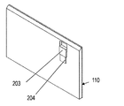
図10は、コネクタ205に、外部機器204が挿入されたアタッチメント203が取り付けられた表示装置110を示している。
次に、図11A~11Cを参照しながら、アタッチメント203を表示装置110に取り付ける手順を示説明する。実施形態1と同様、外部端末204はアタッチメント203に固定されているとする。
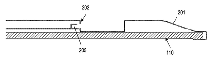
図11Aは、B-B線(図9)における表示装置110の断面図である。段差部202にコネクタ205が設けられていることが理解される。
図11Bは、装着される直前のアタッチメント203と表示装置110との位置関係を示す断面図である。
使用者は、外部端末204が固定されたアタッチメント203の差込部301が設けられた側を凹部90に入れ、そのままバックカバー201または、表示パネル101に沿って、コネクタ205の方向に移動させる。そして、差込部301をコネクタ205に挿入する。挿入および固定の際には、外部端末204及びアタッチメント203の一部をバックカバー201にさらにスライドさせながら、アタッチメント203をコネクタ205に固定することが可能である。
図11Cは、コネクタ205にアタッチメント203の差込部301が挿入されたときの、アタッチメント203と表示装置110との位置関係を示す断面図である。
図11Cに示すように、アタッチメント203とコネクタ205との固定が完了すると、外部端末204と、バックカバー201とは近接した状態で配置され、電気的な接続が確保されることになる。これにより、表示装置110から外部端末204を制御することが可能になる。外部端末204と、バックカバー201とが異なる面上に存在すること、およびその理由は、実施形態1において説明した通りである。
以上、本発明の実施形態を説明した。
従来、外部端末204を表示装置に装着する際には、背面カバーを外した上で、基板が配置された背面の中央付近またはその近傍に電子機器を装着する必要があった。基板の配置の自由度は高いと言えないため、特に表示パネルの大型化によって、使用者のアクセス性が低下していた。
本実施形態によれば、外部端末を内蔵させるためのスペースを表示装置100には設けていない。よって、基板上から外部端末のためのスペースを削減できる。その結果、設計の容易化やコストダウンの実現を促進させることができる。
また、上述の実施形態の構成によれば、表示装置110の背面の段差部をバックカバーの外縁近傍に設け、かつ、その段差部にコネクタを設ければよい。これにより、使用者のアクセス性を向上させることができる。
さらに、表示装置の基板またはバックカバーに対して垂直な方向にアタッチメントを接続するのではなく、平行な方向にスライドさせながら接続するようにした。これにより、使用者は荷重がかけ易くなり操作性が向上する。たとえば、表示装置のバックカバーの外縁近傍に鉛直上向きに開口するコネクタを設けた例を考えると、使用者は、鉛直下向きに架橋部に荷重をかけながらアタッチメントを挿入することが可能になる。非常に容易に取り付けが可能になる。特に、アタッチメントの架橋部に荷重をかけることが可能な程度またはそれ以上の幅を設けることにより、使用者はその架橋部を利用して容易に荷重をかけてアタッチメントをコネクタに押し込むことが可能になる。
なお、荷重をかける方向は鉛直下向きに限られない。横方向や下方向から荷重をかける構成であってもよい。
上述の例では、コネクタは表示装置背面の段差部または凹部に設けられるとしたが、これは一例である。たとえば図12は、表示装置上面を構成するバックカバー201上にコネクタ205が設けられた例を示す。コネクタ205は鉛直方向上向きに開口している。参考のため、表示パネル101とフロントパネル102も示されている。図12に示すように、バックカバー201には段差部や凹部は設けられていないことが理解される。
なお、コネクタ205が設けられる位置は、表示装置の上面に限られない。コネクタ205は、上面、下面および側面の少なくとも1つに設けられていてもよい。
本発明の表示システムは視聴制限解除のための外部端末と表示装置によって形成されるシステムとして有用である。
1 表示システム
100 表示装置
101 表示パネル
102 フロントパネル
201 バックカバー
202 段差部
203 アタッチメント
204 外部端末
205 コネクタ
206 ガイド孔
301 差込部
302 外部端末スロット
303 挿入ガイド
304 架橋部
100 表示装置
101 表示パネル
102 フロントパネル
201 バックカバー
202 段差部
203 アタッチメント
204 外部端末
205 コネクタ
206 ガイド孔
301 差込部
302 外部端末スロット
303 挿入ガイド
304 架橋部
Claims (11)
- 表示装置、外部端末、および前記外部端末を前記表示装置に取り付けるためのアタッチメントを有する表示システムであって、
前記表示装置は、
表示パネルと、
前記表示パネルの裏面を覆うバックカバーであって、前記表示パネルの表示面と略平行な方向に沿ってアタッチメントが差し込まれるコネクタが設けられたバックカバーと
を備えており、
前記アタッチメントは、
前記コネクタと接続される第1インターフェースと、
前記外部端末と接続される第2インターフェースと、
前記第1インターフェースおよび前記第2インターフェースを電気的に接続する架橋部であって、前記外部端末が前記アタッチメントを介して前記表示装置に取り付けられたときに、前記外部端末が前記バックカバーと異なる面上に存在するよう、前記第1インターフェースの位置および前記第2インターフェースの位置を規制する架橋部と
を備えた表示システム。 - 前記外部端末が前記アタッチメントを介して前記表示装置に取り付けられたときにおいて、前記アタッチメントの前記第1および第2インターフェースは、前記表示パネルの表示面と略平行な方向に沿って、前記コネクタおよび前記外部端末にそれぞれ接続されている、請求項1に記載の表示システム。
- 前記バックカバーには、前記表示パネルの表示面に略垂直な面を有する段差部が設けられており、前記コネクタは前記面に設けられている、請求項1に記載の表示システム。
- 前記面はさらに鉛直方向に略垂直である、請求項3に記載の表示システム。
- 前記コネクタは、鉛直方向上向きに開口している、請求項4に記載の表示システム。
- 前記面は前記バックカバーの外縁近傍に設けられている、請求項3に記載の表示システム。
- 前記バックカバーは、前記表示装置の上面、下面および側面の少なくとも1つの面を構成しており、前記コネクタは前記少なくとも1つの面に設けられている、請求項1に記載の表示システム。
- 前記アタッチメントはU字形状である、請求項1に記載の表示システム。
- 前記第1インターフェースは、前記コネクタに差し込まれる端子と、前記端子を前記コネクタに差し込む位置を決めるための少なくとも1つのガイドとを有する、請求項1に記載の表示システム。
- 外部端末を表示装置に取り付けるためのアタッチメントであって、
前記表示装置は、表示パネルと、コネクタが設けられたバックカバーとを有しており、
前記アタッチメントは、
前記コネクタと接続される第1インターフェースと、
前記外部端末と接続される第2インターフェースと、
前記第1インターフェースおよび前記第2インターフェースを電気的に接続する架橋部であって、前記外部端末が前記アタッチメントを介して前記表示装置に取り付けられたときに、前記外部端末が前記バックカバーと異なる面上に存在するよう、前記第1インターフェースの位置および前記第2インターフェースの位置を規制する架橋部と
を備えた、アタッチメント。 - アタッチメントを介して外部端末が接続される表示装置であって、
前記アタッチメントは、
前記表示装置と接続される第1インターフェースと、
前記外部端末と接続される第2インターフェースと、
前記第1インターフェースおよび前記第2インターフェースを電気的に接続する架橋部であって、前記外部端末が前記アタッチメントを介して前記表示装置に取り付けられたときに、前記外部端末が前記バックカバーと異なる面上に存在するよう、前記第1インターフェースの位置および前記第2インターフェースの位置を規制する架橋部と
を有しており、
前記表示装置は、
表示パネルと、
前記表示パネルの裏面を覆うバックカバーであって、前記表示パネルの表示面と略平行な方向に沿って前記アタッチメントの前記第1インターフェースが差し込まれるコネクタが設けられたバックカバーと
を備えた表示装置。
Priority Applications (2)
| Application Number | Priority Date | Filing Date | Title |
|---|---|---|---|
| EP12866494.3A EP2809067B1 (en) | 2012-01-25 | 2012-01-25 | Display system, attachment and display unit |
| PCT/JP2012/000468 WO2013111190A1 (ja) | 2012-01-25 | 2012-01-25 | 表示システム、アタッチメントおよび表示装置 |
Applications Claiming Priority (1)
| Application Number | Priority Date | Filing Date | Title |
|---|---|---|---|
| PCT/JP2012/000468 WO2013111190A1 (ja) | 2012-01-25 | 2012-01-25 | 表示システム、アタッチメントおよび表示装置 |
Publications (1)
| Publication Number | Publication Date |
|---|---|
| WO2013111190A1 true WO2013111190A1 (ja) | 2013-08-01 |
Family
ID=48872971
Family Applications (1)
| Application Number | Title | Priority Date | Filing Date |
|---|---|---|---|
| PCT/JP2012/000468 Ceased WO2013111190A1 (ja) | 2012-01-25 | 2012-01-25 | 表示システム、アタッチメントおよび表示装置 |
Country Status (2)
| Country | Link |
|---|---|
| EP (1) | EP2809067B1 (ja) |
| WO (1) | WO2013111190A1 (ja) |
Citations (3)
| Publication number | Priority date | Publication date | Assignee | Title |
|---|---|---|---|---|
| JPH11233964A (ja) * | 1998-02-16 | 1999-08-27 | Sony Computer Entertainment Inc | 電子機器用保護ケース |
| JP2001094272A (ja) * | 1999-09-24 | 2001-04-06 | Yamatake Corp | 電気機器 |
| JP2007250926A (ja) | 2006-03-17 | 2007-09-27 | Hitachi Ltd | ケーブルカード装着装置及びテレビジョン受信機 |
Family Cites Families (1)
| Publication number | Priority date | Publication date | Assignee | Title |
|---|---|---|---|---|
| JP2003288565A (ja) * | 2002-03-27 | 2003-10-10 | Nec Corp | メモリユニットおよびこれを用いる携帯機器 |
-
2012
- 2012-01-25 EP EP12866494.3A patent/EP2809067B1/en active Active
- 2012-01-25 WO PCT/JP2012/000468 patent/WO2013111190A1/ja not_active Ceased
Patent Citations (3)
| Publication number | Priority date | Publication date | Assignee | Title |
|---|---|---|---|---|
| JPH11233964A (ja) * | 1998-02-16 | 1999-08-27 | Sony Computer Entertainment Inc | 電子機器用保護ケース |
| JP2001094272A (ja) * | 1999-09-24 | 2001-04-06 | Yamatake Corp | 電気機器 |
| JP2007250926A (ja) | 2006-03-17 | 2007-09-27 | Hitachi Ltd | ケーブルカード装着装置及びテレビジョン受信機 |
Non-Patent Citations (1)
| Title |
|---|
| See also references of EP2809067A4 * |
Also Published As
| Publication number | Publication date |
|---|---|
| EP2809067A1 (en) | 2014-12-03 |
| EP2809067A4 (en) | 2015-10-21 |
| EP2809067B1 (en) | 2016-12-21 |
Similar Documents
| Publication | Publication Date | Title |
|---|---|---|
| JP3920786B2 (ja) | 液晶表示装置 | |
| EP3139242B1 (en) | Architecture features on an electronic device | |
| US20110255250A1 (en) | Printed circuit board components for electronic devices | |
| US20160066481A1 (en) | Electromagnetic Shielding Structures | |
| KR20090080009A (ko) | 패널형 디스플레이장치 | |
| US9270923B2 (en) | Television receiver and electronic device | |
| JP5377694B2 (ja) | 電子機器 | |
| US10139955B2 (en) | Display unit for vehicle and display control unit | |
| US8525046B2 (en) | Electronic apparatus | |
| EP3595274B1 (en) | Bracket for electronic component, electronic component assembly and mobile terminal | |
| WO2013111190A1 (ja) | 表示システム、アタッチメントおよび表示装置 | |
| JP2010128001A (ja) | 薄型表示装置 | |
| JP2019091979A (ja) | 電子制御装置 | |
| JP2011053447A (ja) | プラズマディスプレイ装置 | |
| JP2008199229A (ja) | 外部接続コネクタの補強構造及び該補強構造を備える電子機器 | |
| JP5250702B2 (ja) | 電子機器 | |
| JP2014209425A (ja) | 携帯端末装置 | |
| US20130335924A1 (en) | Option board exchange mechanism in display apparatus, and display apparatus | |
| JP6245917B2 (ja) | 回路基板、及び電子機器 | |
| JP2008009904A (ja) | 電子機器 | |
| JP2006310965A (ja) | デジタル放送受信装置 | |
| JP2013187884A (ja) | 携帯端末装置 | |
| US20140226294A1 (en) | Display device | |
| JP2010219433A (ja) | 電子機器 | |
| JP2011259082A (ja) | 電子機器 |
Legal Events
| Date | Code | Title | Description |
|---|---|---|---|
| 121 | Ep: the epo has been informed by wipo that ep was designated in this application |
Ref document number: 12866494 Country of ref document: EP Kind code of ref document: A1 |
|
| NENP | Non-entry into the national phase |
Ref country code: DE |
|
| REEP | Request for entry into the european phase |
Ref document number: 2012866494 Country of ref document: EP |
|
| WWE | Wipo information: entry into national phase |
Ref document number: 2012866494 Country of ref document: EP |
|
| NENP | Non-entry into the national phase |
Ref country code: JP |