WO2013111190A1 - Système d'affichage, point de raccordement et module d'affichage - Google Patents
Système d'affichage, point de raccordement et module d'affichage Download PDFInfo
- Publication number
- WO2013111190A1 WO2013111190A1 PCT/JP2012/000468 JP2012000468W WO2013111190A1 WO 2013111190 A1 WO2013111190 A1 WO 2013111190A1 JP 2012000468 W JP2012000468 W JP 2012000468W WO 2013111190 A1 WO2013111190 A1 WO 2013111190A1
- Authority
- WO
- WIPO (PCT)
- Prior art keywords
- attachment
- external terminal
- display device
- display
- connector
- Prior art date
- Legal status (The legal status is an assumption and is not a legal conclusion. Google has not performed a legal analysis and makes no representation as to the accuracy of the status listed.)
- Ceased
Links
Images







Classifications
-
- H—ELECTRICITY
- H04—ELECTRIC COMMUNICATION TECHNIQUE
- H04N—PICTORIAL COMMUNICATION, e.g. TELEVISION
- H04N5/00—Details of television systems
- H04N5/64—Constructional details of receivers, e.g. cabinets or dust covers
Definitions
- the present invention relates to a display system. More specifically, the present invention relates to a display system having a display device and an attachment, wherein the external system used for the display device is inserted into the attachment and used.
- Some conventional display devices which extend the function of the display device by connecting an external terminal.
- an external terminal connected to the display device, a card equipped with an IC for decrypting an encrypted broadcast signal, a recording medium, and a communication module can be cited.
- a slot for inserting an external terminal is mounted on the internal substrate.
- the slot for inserting the external terminal or the external terminal itself occupies the space on the substrate, and there is a problem that it is difficult to facilitate the design and cost reduction of the display device.
- the conventional technology assumes that most of the external terminals are stored in the display device. Therefore, it is necessary to secure a space (for example, a slot) for storing the external terminal on the substrate in the display device.
- an external terminal is basically a matter selected by the user. That is, even if a space for storing the external terminal is secured on the substrate, the external terminal may not be used at all. In such a case, the space for the external terminal on the board is wasted. If the space for the external terminal can be reduced from the substrate, the design can be facilitated and the cost can be reduced.
- the present invention has been made to solve the above problems, and an object of the present invention is to provide a display system in which a space for storing an external terminal is not provided on a substrate of a display device.
- the display system includes a display device, an external terminal, and an attachment for attaching the external terminal to the display device.
- the display device includes a display panel and a back cover that covers a back surface of the display panel, and is provided with a connector into which an attachment is inserted along a direction substantially parallel to the display surface of the display panel.
- the attachment is a first interface connected to the connector, a second interface connected to the external terminal, and a bridging portion that electrically connects the first interface and the second interface.
- the position of the first interface and the position of the second interface are arranged so that the external terminal is on a different surface from the back cover when the external terminal is attached to the display device via the attachment. And a bridging portion to be regulated.
- the first and second interfaces of the attachment are arranged along the direction substantially parallel to the display surface of the display panel and the connector and Each may be connected to an external terminal.
- the back cover may be provided with a step portion having a surface substantially perpendicular to the display surface of the display panel, and the connector may be provided on the surface.
- the surface may be substantially perpendicular to the vertical direction.
- the connector may open upward in the vertical direction.
- the surface may be provided near the outer edge of the back cover.
- the back cover may constitute at least one of an upper surface, a lower surface, and a side surface of the display device, and the connector may be provided on the at least one surface.
- the attachment may be U-shaped.
- the first interface may include a terminal inserted into the connector and at least one guide for determining a position where the terminal is inserted into the connector.
- An attachment according to the present invention is an attachment for attaching an external terminal to a display device, and the display device includes a display panel and a back cover provided with a connector, and the attachment includes the connector and the connector.
- a bridging portion that regulates the position of the first interface and the position of the second interface is provided so that the external terminal exists on a different surface from the back cover when attached to the display device.
- the display device is a display device to which an external terminal is connected via an attachment, and the attachment includes a first interface connected to the display device, and a second interface connected to the external terminal.
- a bridging portion for electrically connecting the first interface and the second interface, wherein the external terminal is different from the back cover when the external terminal is attached to the display device via the attachment.
- the display device includes a bridging portion that regulates the position of the first interface and the position of the second interface so as to exist on a surface, and the display device covers a display panel and a back cover of the display panel And the attachment of the attachment along a direction substantially parallel to the display surface of the display panel.
- Connector serial first interface is plugged in and a back cover provided.
- the attachment to which the external terminal is connected is connected to the back cover via the connector formed in the step portion of the back cover of the display device.
- an external terminal can be connected to the display device.
- FIG. 1 is a diagram showing a display system 10 in which an external terminal 204 is attached to a display device 100 via an attachment 203.
- FIG. 1 is an internal configuration diagram of a back surface of a display device 100 of a display system 10 according to Embodiment 1.
- FIG. 3 is a partially enlarged view of a connector 205. It is an enlarged view of the attachment 203 concerning Embodiment 1.
- FIG. It is sectional drawing of the attachment 203 in an AA line (FIG. 6). 3 is a cross-sectional view showing a positional relationship between an attachment 203 and a display device 100 immediately before being mounted.
- FIG. 1 is a diagram showing a display system 10 in which an external terminal 204 is attached to a display device 100 via an attachment 203.
- FIG. 1 is an internal configuration diagram of a back surface of a display device 100 of a display system 10 according to Embodiment 1.
- FIG. 3 is a partially enlarged view of a connector 205. It is an enlarged
- FIG. 6 is a cross-sectional view showing a positional relationship between the attachment 203 and the display device 100 when the attachment 203 is fixed to the connector 205.
- FIG. FIG. 6 is a rear view of a display device 110 according to a second embodiment. It is a figure which shows the display apparatus 110 with which the attachment 203 by which the external apparatus 204 was inserted in the connector 205 was attached. It is sectional drawing of the display apparatus 110 in the BB line (FIG. 9). It is sectional drawing which shows the positional relationship of the attachment 203 and the display apparatus 110 just before mounting
- FIG. 6 is a cross-sectional view showing the positional relationship between the attachment 203 and the display device 110 when the insertion part 301 of the attachment 203 is inserted into the connector 205. It is a figure which shows the example in which the connector 205 was provided on the back cover 201 which comprises a display apparatus upper surface.
- the display system has a display device, an external terminal, and an attachment for connecting the display device and the external terminal.
- a space for incorporating an external terminal is not provided in the display device.
- a connector into which an attachment is inserted is provided on the back cover.
- the external terminal is attached to the display device 100 via an attachment.
- the connector on the display device side for attaching the attachment is located at a position where the user can easily attach the attachment, for example, a step provided on the back cover, or when the back cover is attached to the display device. It is provided at any position on the top, bottom and side surfaces of the display device.
- the attachment in a substantially U shape, the user can easily and surely attach the attachment to the display device so as to be hooked.
- FIG. 1 is a front view of a display device 100 according to the present embodiment.
- the display device 100 includes a display panel 101 and a front panel 102.
- the display device 100 converts a broadcast signal or data recorded on an external recording medium into a video signal and displays it.
- Examples of the display device 100 include a television receiver and a general-purpose display.
- the display panel 101 displays a video corresponding to the video signal.
- the display panel 101 can be composed of a plasma display panel, a liquid crystal panel, an organic EL panel, or the like.
- the front panel 102 is a frame that holds the display panel 101. Resin or metal is used as the material of the front panel 102.
- FIG. 2 is a rear view of the display device 100.
- the display device 100 includes a back cover 201.
- the back cover 201 covers the back surface of the display panel 101.
- the back cover 201 is coupled to the front panel 102 and holds the display panel 101. Resin or metal is used as the material of the back cover 201.
- the back cover 201 is provided with a stepped portion 202.
- the stepped portion 202 rises in a direction substantially perpendicular to the vertical direction.
- the stepped portion 202 rises in a substantially vertical direction from the main plane constituting the back cover 201.
- the “main plane” here means a plane constituted by four sides of the back cover 201 on the drawing.
- the shape of the illustrated back cover 201 is merely an example, and various shapes such as a curved shape are conceivable, so the “main plane” may not be clearly defined.
- the display surface of the display panel 101 is generally a flat surface as shown in FIG. Therefore, in this specification, the position of the stepped portion 202 or the like may be specified in relation to the display panel 101.
- the stepped portion 202 protrudes in a direction substantially perpendicular to the display surface of the display panel 101 or on the back side when the display panel 101 is the front surface.
- a connector 205 to which the attachment 203 is connected is disposed on the step portion 202 of the back cover 201.
- the attachment 203 is inserted into the connector 205 along a direction substantially parallel to the display surface of the display panel 101.
- An external terminal 204 is attached to the attachment 203.
- Two guide holes 206 are provided in the vicinity of the connector 205. Insertion guides for attachments 203 to be described later are inserted into the two guide holes 206.
- the external terminal 204 has a card shape conforming to the PCMCIA standard.
- the external terminal 204 is a CI module (CI card) related to digital television broadcasting in Europe, for example.
- the external terminal 204 has a function of releasing the encryption applied to the broadcast signal received by the display device 100. Details will be described later.
- FIG. 2 shows the attachment 203 to which the external terminal 204 is attached.
- the display device 100, the external terminal 204, and the attachment 203 for attaching the external terminal 204 to the display device 100 may be collectively referred to as the display system 10.
- the back cover 201 only needs to constitute at least a part of the back surface of the display device 100 and have a configuration to which the attachment 203 can be connected. Other configurations are not particularly limited.
- the back cover 201 is not necessarily combined with the front panel 102.
- the stepped portion 202 protrudes from the back side as viewed from the display panel 101.
- the stepped portion 202 is formed of the same member as the back cover 201.
- the stepped portion 202 only needs to protrude from the main plane of the back cover 201, and other configurations are not particularly limited.
- the back cover 201 itself may be flat, and a cover including the stepped portion 202 may be connected from above.
- the attachment 203 is connected to a connector provided in the step portion 202.
- FIG. 3 shows the display system 10 in which the external terminal 204 is attached to the display device 100 via the attachment 203.
- the attachment 203 is inserted into the connector 205 (FIG. 2) disposed in the stepped portion 202 of the back cover 201 along a direction substantially parallel to the display surface of the display panel 101. A more detailed description will be given later.
- FIG. 4 is an internal configuration diagram of the back surface of the display device 100 of the display system 10 according to the present embodiment.
- FIG. 4 shows the back of the display device 100 with the back cover 201 removed.
- a substrate 401 is provided inside the back surface of the display device 100.
- a connector 205 is mounted on the substrate 401.
- An electric circuit for processing an electric signal from the connector 205 is further mounted on the substrate 402.
- a space for providing the external terminal 204 is not provided on the substrate 401. Only such a connector 205 for external equipment is provided without providing such a space. As a result, the size of the substrate 401 can be reduced.
- FIG. 5 is a partially enlarged view of the connector 205.
- the connector 205 is positioned so as to appear at the stepped portion 202 through an opening provided in the back cover 201.
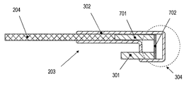
- FIG. 6 is an enlarged view of the attachment 203 according to the present embodiment.
- the attachment 203 includes an insertion portion 301 that is a first interface, an external terminal slot 302 that is a second interface, an insertion guide 303, and a bridging portion 304.
- the insertion part 301 is inserted into the connector 205.
- the insertion part 301 is comprised from the several insertion member.
- the display device 100 and the attachment 203 are fixed by inserting the insertion portion 301 into the slot of the outer periphery 202.
- External terminal 204 is inserted into external terminal slot 302.
- the attachment 203 and the external terminal 204 are fixed.
- the external terminal 204 can be electrically connected to the insertion unit 301. In this way, the external terminal 204 is connected to the display device 100 in a circuit. That is, the display device 100 can use the function of the external terminal 204.
- the orientation of the external terminal slot 302 when the attachment 203 is fixed to the display device 100 is defined so that the external terminal 204 inserted into the external terminal slot 302 is parallel to the plug-in portion 301.
- the insertion guide 303 functions as a guide when the insertion part 301 is inserted into the connector 205.
- the insertion guide 303 is inserted into a guide hole 206 (FIG. 2) disposed in the vicinity of the connector 205.
- the insertion part 301 has a function which maintains a connection so that the insertion part 301 and the connector 205 may not remove
- each of the insertion guides 303 is positioned so as to contact the outer periphery of the connector 205.
- the connector 205 is sandwiched between the insertion portion 301 and the insertion guide 303, and the insertion portion 301 and the connector 205 are unlikely to come off.
- the insertion guide 303 is installed in parallel with the direction in which the substrate 401 (FIG. 4) constituting the electronic device spreads. Thereby, the influence with respect to the thickness of the housing
- Various configurations of the insertion guide 303 are conceivable, but if the configuration shown in FIG. 6 is adopted, the display device 100 can also be made thinner.
- the insertion guide 303 in the present embodiment has a structure capable of protecting the insertion portion 301.
- the insertion guide 303 is configured to be longer than the insertion part 301.
- the insertion guide 303 is disposed outward from the insertion portion 301.
- the “outward direction” means a direction opposite to the external terminal slot 302 on the bridging portion 304.
- insertion guides 303 there are two insertion guides 303, but the number is arbitrary. It is sufficient that at least one exists. However, it is not essential to provide an insertion guide.
- the bridging part 304 physically connects the insertion part 301 and the insertion guide 303 to the external terminal slot 302.
- the bridging portion 304 also electrically connects the insertion portion 301 and the external terminal slot 302.
- the cross section of the attachment 203 is substantially U-shaped.
- FIG. 7 is a cross-sectional view of the attachment 203 taken along line AA (FIG. 6).
- the external terminal 204 inserted into the external terminal slot 302 is also shown in the figure.
- the external terminal 204 is connected to the terminal group 701 of the attachment 203 and is electrically connected to the plug-in part 301 via the wiring 702 in the bridging part 304.
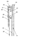
- FIG. 8A is a cross-sectional view showing a positional relationship between the attachment 203 and the display device 100 immediately before being mounted.
- the user moves the attachment 203 to which the external terminal 204 is fixed along the back cover 201 or the display panel 101 in the direction of the connector 205. Then, the insertion part 301 is inserted into the connector 205. At the time of insertion and fixing, the attachment 203 can be fixed to the connector 205 while further sliding part of the external terminal 204 and the attachment 203 on the back cover 201.
- the external terminal 204 and the back cover 201 are arranged in a close proximity.
- the external terminal 204 and the back cover 201 are not arranged on the same surface but are on different surfaces. This is because the bridging portion 304 has a substantially U shape and restricts (shifts) the positions of the insertion portion 301 and the external terminal slot 302. Electrical connection will be ensured. Thereby, it is possible to control the external terminal 204 from the display device 100.
- FIG. 9 is a rear view of the display device 110 according to the present embodiment.
- Constituent elements corresponding to the constituent elements of the display device 100 of Embodiment 1 are denoted by the same reference numerals and are referred to by the same names.
- Embodiment 1 it has been described that a part of the back cover 201 protrudes toward the back side when the display panel is the front side.
- the back cover 201 of the display device 110 is provided with a recess 90.
- a plurality of surfaces substantially perpendicular to the display panel that form the recesses 90 correspond to the stepped portion 202 according to the first embodiment.
- the connector 205 is provided at the stepped portion 202.
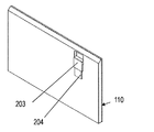
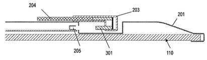
- FIG. 10 shows the display device 110 in which an attachment 203 into which an external device 204 is inserted is attached to the connector 205.
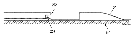
- FIG. 11A is a cross-sectional view of the display device 110 taken along the line BB (FIG. 9). It will be understood that the connector 205 is provided in the stepped portion 202.
- FIG. 11B is a cross-sectional view showing the positional relationship between the attachment 203 and the display device 110 immediately before being mounted.
- the user puts the side of the attachment 203 on which the external terminal 204 is fixed to the insertion portion 301 into the concave portion 90 and moves it in the direction of the connector 205 along the back cover 201 or the display panel 101 as it is. Then, the insertion part 301 is inserted into the connector 205. At the time of insertion and fixing, the attachment 203 can be fixed to the connector 205 while further sliding part of the external terminal 204 and the attachment 203 on the back cover 201.
- FIG. 11C is a cross-sectional view showing a positional relationship between the attachment 203 and the display device 110 when the insertion portion 301 of the attachment 203 is inserted into the connector 205.
- the external terminal 204 and the back cover 201 are arranged in close proximity to ensure electrical connection. As a result, the external terminal 204 can be controlled from the display device 110.
- the fact that the external terminal 204 and the back cover 201 are on different surfaces and the reason are as described in the first embodiment.
- the display device 100 is not provided with a space for incorporating an external terminal. Therefore, the space for the external terminal can be reduced from the substrate. As a result, simplification of design and realization of cost reduction can be promoted.
- the stepped portion on the back surface of the display device 110 may be provided near the outer edge of the back cover, and the connector may be provided on the stepped portion.
- the direction in which the load is applied is not limited to the vertically downward direction.
- the structure which applies a load from a horizontal direction or a downward direction may be sufficient.
- the connector is provided in the stepped portion or the recessed portion on the rear surface of the display device, but this is an example.
- FIG. 12 shows an example in which a connector 205 is provided on a back cover 201 constituting the upper surface of the display device.
- the connector 205 opens upward in the vertical direction.
- a display panel 101 and a front panel 102 are also shown.
- the back cover 201 is not provided with a step portion or a recess.
- the position where the connector 205 is provided is not limited to the upper surface of the display device.
- the connector 205 may be provided on at least one of the upper surface, the lower surface, and the side surface.
- the display system of the present invention is useful as a system formed by an external terminal and a display device for releasing viewing restrictions.
Landscapes
- Engineering & Computer Science (AREA)
- Multimedia (AREA)
- Signal Processing (AREA)
- Devices For Indicating Variable Information By Combining Individual Elements (AREA)
Abstract
La présente invention se rapporte à un système d'affichage dans lequel un espace pour recevoir une borne externe n'est pas prévu sur un substrat. Le système d'affichage selon l'invention comprend : un module d'affichage ; une borne externe ; et un point de raccordement qui permet de raccorder la borne externe au module d'affichage. Le module d'affichage selon l'invention comprend : un écran d'affichage ; et un couvercle arrière. Ledit couvercle arrière est utilisé afin de couvrir la surface arrière de l'écran d'affichage. Sur cette surface arrière, un connecteur devant être utilisé en vue du raccordement, est prévu dans une direction sensiblement parallèle à la surface d'affichage de l'écran d'affichage. Le point de raccordement selon l'invention comprend : une première interface devant être raccordée au connecteur ; une seconde interface devant être raccordée à la borne externe ; et une section de raccordement en pont. Ladite section de raccordement en pont est utilisée afin de connecter électriquement la première interface à la seconde interface. Ladite section de raccordement en pont a pour but de réguler la position de la première interface et la position de la seconde interface de telle sorte que la borne externe se trouve sur un plan différent de celui du couvercle arrière quand la borne externe est raccordée au module d'affichage via le point de raccordement.
Priority Applications (2)
| Application Number | Priority Date | Filing Date | Title |
|---|---|---|---|
| EP12866494.3A EP2809067B1 (fr) | 2012-01-25 | 2012-01-25 | Système d'affichage, point de raccordement et module d'affichage |
| PCT/JP2012/000468 WO2013111190A1 (fr) | 2012-01-25 | 2012-01-25 | Système d'affichage, point de raccordement et module d'affichage |
Applications Claiming Priority (1)
| Application Number | Priority Date | Filing Date | Title |
|---|---|---|---|
| PCT/JP2012/000468 WO2013111190A1 (fr) | 2012-01-25 | 2012-01-25 | Système d'affichage, point de raccordement et module d'affichage |
Publications (1)
| Publication Number | Publication Date |
|---|---|
| WO2013111190A1 true WO2013111190A1 (fr) | 2013-08-01 |
Family
ID=48872971
Family Applications (1)
| Application Number | Title | Priority Date | Filing Date |
|---|---|---|---|
| PCT/JP2012/000468 Ceased WO2013111190A1 (fr) | 2012-01-25 | 2012-01-25 | Système d'affichage, point de raccordement et module d'affichage |
Country Status (2)
| Country | Link |
|---|---|
| EP (1) | EP2809067B1 (fr) |
| WO (1) | WO2013111190A1 (fr) |
Citations (3)
| Publication number | Priority date | Publication date | Assignee | Title |
|---|---|---|---|---|
| JPH11233964A (ja) * | 1998-02-16 | 1999-08-27 | Sony Computer Entertainment Inc | 電子機器用保護ケース |
| JP2001094272A (ja) * | 1999-09-24 | 2001-04-06 | Yamatake Corp | 電気機器 |
| JP2007250926A (ja) | 2006-03-17 | 2007-09-27 | Hitachi Ltd | ケーブルカード装着装置及びテレビジョン受信機 |
Family Cites Families (1)
| Publication number | Priority date | Publication date | Assignee | Title |
|---|---|---|---|---|
| JP2003288565A (ja) * | 2002-03-27 | 2003-10-10 | Nec Corp | メモリユニットおよびこれを用いる携帯機器 |
-
2012
- 2012-01-25 EP EP12866494.3A patent/EP2809067B1/fr active Active
- 2012-01-25 WO PCT/JP2012/000468 patent/WO2013111190A1/fr not_active Ceased
Patent Citations (3)
| Publication number | Priority date | Publication date | Assignee | Title |
|---|---|---|---|---|
| JPH11233964A (ja) * | 1998-02-16 | 1999-08-27 | Sony Computer Entertainment Inc | 電子機器用保護ケース |
| JP2001094272A (ja) * | 1999-09-24 | 2001-04-06 | Yamatake Corp | 電気機器 |
| JP2007250926A (ja) | 2006-03-17 | 2007-09-27 | Hitachi Ltd | ケーブルカード装着装置及びテレビジョン受信機 |
Non-Patent Citations (1)
| Title |
|---|
| See also references of EP2809067A4 * |
Also Published As
| Publication number | Publication date |
|---|---|
| EP2809067A1 (fr) | 2014-12-03 |
| EP2809067A4 (fr) | 2015-10-21 |
| EP2809067B1 (fr) | 2016-12-21 |
Similar Documents
| Publication | Publication Date | Title |
|---|---|---|
| JP3920786B2 (ja) | 液晶表示装置 | |
| EP3139242B1 (fr) | Éléments d'architecture sur un dispositif électronique | |
| US20110255250A1 (en) | Printed circuit board components for electronic devices | |
| US20160066481A1 (en) | Electromagnetic Shielding Structures | |
| KR20090080009A (ko) | 패널형 디스플레이장치 | |
| US9270923B2 (en) | Television receiver and electronic device | |
| JP5377694B2 (ja) | 電子機器 | |
| US10139955B2 (en) | Display unit for vehicle and display control unit | |
| US8525046B2 (en) | Electronic apparatus | |
| EP3595274B1 (fr) | Support pour composant électronique, ensemble de composant électronique et terminal mobile | |
| WO2013111190A1 (fr) | Système d'affichage, point de raccordement et module d'affichage | |
| JP2010128001A (ja) | 薄型表示装置 | |
| JP2019091979A (ja) | 電子制御装置 | |
| JP2011053447A (ja) | プラズマディスプレイ装置 | |
| JP2008199229A (ja) | 外部接続コネクタの補強構造及び該補強構造を備える電子機器 | |
| JP5250702B2 (ja) | 電子機器 | |
| JP2014209425A (ja) | 携帯端末装置 | |
| US20130335924A1 (en) | Option board exchange mechanism in display apparatus, and display apparatus | |
| JP6245917B2 (ja) | 回路基板、及び電子機器 | |
| JP2008009904A (ja) | 電子機器 | |
| JP2006310965A (ja) | デジタル放送受信装置 | |
| JP2013187884A (ja) | 携帯端末装置 | |
| US20140226294A1 (en) | Display device | |
| JP2010219433A (ja) | 電子機器 | |
| JP2011259082A (ja) | 電子機器 |
Legal Events
| Date | Code | Title | Description |
|---|---|---|---|
| 121 | Ep: the epo has been informed by wipo that ep was designated in this application |
Ref document number: 12866494 Country of ref document: EP Kind code of ref document: A1 |
|
| NENP | Non-entry into the national phase |
Ref country code: DE |
|
| REEP | Request for entry into the european phase |
Ref document number: 2012866494 Country of ref document: EP |
|
| WWE | Wipo information: entry into national phase |
Ref document number: 2012866494 Country of ref document: EP |
|
| NENP | Non-entry into the national phase |
Ref country code: JP |