WO2013111483A1 - Appareil d'alimentation en papier et appareil de formation d'image - Google Patents
Appareil d'alimentation en papier et appareil de formation d'image Download PDFInfo
- Publication number
- WO2013111483A1 WO2013111483A1 PCT/JP2012/083115 JP2012083115W WO2013111483A1 WO 2013111483 A1 WO2013111483 A1 WO 2013111483A1 JP 2012083115 W JP2012083115 W JP 2012083115W WO 2013111483 A1 WO2013111483 A1 WO 2013111483A1
- Authority
- WO
- WIPO (PCT)
- Prior art keywords
- paper
- fan
- separation
- suction
- duct
- Prior art date
- Legal status (The legal status is an assumption and is not a legal conclusion. Google has not performed a legal analysis and makes no representation as to the accuracy of the status listed.)
- Ceased
Links
Images





Classifications
-
- B—PERFORMING OPERATIONS; TRANSPORTING
- B65—CONVEYING; PACKING; STORING; HANDLING THIN OR FILAMENTARY MATERIAL
- B65H—HANDLING THIN OR FILAMENTARY MATERIAL, e.g. SHEETS, WEBS, CABLES
- B65H3/00—Separating articles from piles
- B65H3/08—Separating articles from piles using pneumatic force
- B65H3/14—Air blasts producing partial vacuum
-
- B—PERFORMING OPERATIONS; TRANSPORTING
- B65—CONVEYING; PACKING; STORING; HANDLING THIN OR FILAMENTARY MATERIAL
- B65H—HANDLING THIN OR FILAMENTARY MATERIAL, e.g. SHEETS, WEBS, CABLES
- B65H3/00—Separating articles from piles
- B65H3/46—Supplementary devices or measures to assist separation or prevent double feed
- B65H3/48—Air blast acting on edges of, or under, articles
-
- B—PERFORMING OPERATIONS; TRANSPORTING
- B65—CONVEYING; PACKING; STORING; HANDLING THIN OR FILAMENTARY MATERIAL
- B65H—HANDLING THIN OR FILAMENTARY MATERIAL, e.g. SHEETS, WEBS, CABLES
- B65H1/00—Supports or magazines for piles from which articles are to be separated
- B65H1/08—Supports or magazines for piles from which articles are to be separated with means for advancing the articles to present the articles to the separating device
- B65H1/14—Supports or magazines for piles from which articles are to be separated with means for advancing the articles to present the articles to the separating device comprising positively-acting mechanical devices
-
- B—PERFORMING OPERATIONS; TRANSPORTING
- B65—CONVEYING; PACKING; STORING; HANDLING THIN OR FILAMENTARY MATERIAL
- B65H—HANDLING THIN OR FILAMENTARY MATERIAL, e.g. SHEETS, WEBS, CABLES
- B65H3/00—Separating articles from piles
- B65H3/08—Separating articles from piles using pneumatic force
- B65H3/12—Suction bands, belts, or tables moving relatively to the pile
- B65H3/124—Suction bands or belts
- B65H3/128—Suction bands or belts separating from the top of pile
-
- B—PERFORMING OPERATIONS; TRANSPORTING
- B65—CONVEYING; PACKING; STORING; HANDLING THIN OR FILAMENTARY MATERIAL
- B65H—HANDLING THIN OR FILAMENTARY MATERIAL, e.g. SHEETS, WEBS, CABLES
- B65H5/00—Feeding articles separated from piles; Feeding articles to machines
- B65H5/22—Feeding articles separated from piles; Feeding articles to machines by air-blast or suction device
- B65H5/222—Feeding articles separated from piles; Feeding articles to machines by air-blast or suction device by suction devices
-
- B—PERFORMING OPERATIONS; TRANSPORTING
- B65—CONVEYING; PACKING; STORING; HANDLING THIN OR FILAMENTARY MATERIAL
- B65H—HANDLING THIN OR FILAMENTARY MATERIAL, e.g. SHEETS, WEBS, CABLES
- B65H2403/00—Power transmission; Driving means
- B65H2403/50—Driving mechanisms
- B65H2403/54—Driving mechanisms other
- B65H2403/544—Driving mechanisms other involving rolling up - unrolling of transmission element, e.g. winch
-
- B—PERFORMING OPERATIONS; TRANSPORTING
- B65—CONVEYING; PACKING; STORING; HANDLING THIN OR FILAMENTARY MATERIAL
- B65H—HANDLING THIN OR FILAMENTARY MATERIAL, e.g. SHEETS, WEBS, CABLES
- B65H2405/00—Parts for holding the handled material
- B65H2405/10—Cassettes, holders, bins, decks, trays, supports or magazines for sheets stacked substantially horizontally
- B65H2405/15—Large capacity supports arrangements
-
- B—PERFORMING OPERATIONS; TRANSPORTING
- B65—CONVEYING; PACKING; STORING; HANDLING THIN OR FILAMENTARY MATERIAL
- B65H—HANDLING THIN OR FILAMENTARY MATERIAL, e.g. SHEETS, WEBS, CABLES
- B65H2406/00—Means using fluid
- B65H2406/30—Suction means
- B65H2406/36—Means for producing, distributing or controlling suction
- B65H2406/364—Means for producing, distributing or controlling suction simultaneously blowing and sucking
-
- B—PERFORMING OPERATIONS; TRANSPORTING
- B65—CONVEYING; PACKING; STORING; HANDLING THIN OR FILAMENTARY MATERIAL
- B65H—HANDLING THIN OR FILAMENTARY MATERIAL, e.g. SHEETS, WEBS, CABLES
- B65H2406/00—Means using fluid
- B65H2406/40—Fluid power drive; Fluid supply elements
- B65H2406/42—Distribution circuits
Definitions
- the present invention relates to a sheet feeding device including a sheet transporting member that sucks and transports sheets stacked on a sheet stacking table, and an image forming apparatus including the sheet feeding device.
- image forming apparatuses such as printers and copiers are provided with a paper feeding device that sequentially takes out sheets stacked on a paper feeding tray one by one and feeds them toward an image forming unit.
- Various methods such as a claw separation method, a friction pad method, and a gate method are applied to the sheet feeding device in order to separate the sheets stacked on the sheet feeding tray one by one.
- a number of methods have been developed for blowing air on paper to lift it up and separate it.
- Patent Document 2 As another form of the paper feeding device, it has been studied to improve the paper separation by forming the paper adsorbed on the transport belt in a wave shape (see, for example, Patent Document 2).
- air is ejected toward the paper by a blower fan, and the paper is adsorbed on the transport belt by a suction fan via a suction duct having a suction port provided on the bottom wall.
- the conveying belt is curved by a rib formed so as to protrude from the bottom wall of the suction duct, and the sucked paper is formed in a wave shape.
- a gap for air to enter is provided between the sucked paper and the paper placed on the paper placement plate.
- the fan blowout port of one fan and the fan suction port of the other fan are connected by a connecting air passage, and air is sucked in by two fans and the sheet is fed to the conveyor belt.
- Adsorb The air blown out from the fan outlet of the other fan is blown out to the paper storage unit provided with the paper mounting table.
- the paper feeding device includes a floating air blowing mechanism that blows air to the side surface of the paper placed on the paper placing table and a separation air blowing mechanism that blows air from the front of the paper adsorbed to the conveyance belt. Lift and separate. That is, by arranging the two fans in series, the suction forces of the individual fans are added so that a sufficient suction force can be obtained.
- the sheet feeding apparatus described in Patent Document 4 includes an air supply unit in which an air blowing port of an upstream fan and an air suction port of a downstream fan are connected by a spiral flow path.
- an air blowing port of an upstream fan and an air suction port of a downstream fan are connected by a spiral flow path.
- Several sheets of the sheet bundle set on the sheet table are floated by the air blown from the air supply means.
- a suction conveyance unit provided with a suction fan is disposed above the sheet bundle, and the sheet floating from the sheet table is sucked to the transport belt by sucking air with the suction fan. That is, high pressure air is obtained by two connected fans, so that the sheet is reliably separated and floated.
- the fan used in the paper feeder required a strong suction force to reliably separate and float the paper. Therefore, in order to increase the suction force of the fan, it is necessary to take measures such as using a large fan. However, when a large fan is applied, there is a problem that it cannot be operated using a power source common to the image forming apparatus.
- the fan used in the paper feeder required a strong suction force to reliably separate and float the paper. Therefore, in order to increase the suction force of the fan, it is necessary to take measures such as using a large fan. However, when a large fan is applied, there is a problem that it cannot be operated using a power source common to the image forming apparatus.
- the paper feeding device described in Patent Document 2 also has a problem that a sufficient suction force cannot be obtained because the suction fan and the blower fan are provided independently.
- the fan suction port is formed along the axial direction of the impeller, and the fan outlet is formed in the tangential direction of the impeller.
- the two fans are arranged so as to overlap each other with the fan suction port facing upward. That is, since the fan outlet of one fan and the fan inlet of the other fan are formed in different directions, the connecting air passage connecting the two fans requires a bent portion. In the bent part, the air flow is lost by obstructing the air flow by an obstacle such as a wall surface. Therefore, in the structure of the paper feeding device described above, there is a problem that it is not possible to avoid a reduction in suction force when passing through the connection air passage. In addition, the above-described paper feeding device requires a fan for floating the paper separately from the fans connected in series.
- the present invention provides a paper feeding device and an image forming apparatus that can mutually strengthen a force for sucking paper and a force for separating paper by connecting the suction fan and the separation fan.
- An object is to provide an apparatus.
- the paper feeding apparatus In order to reduce the size and increase the functionality of the image forming apparatus, the paper feeding apparatus is required to be further downsized. In other words, it has been studied to reduce the area occupied by the sheet feeding device, to reduce the size of the housing, and to add more parts.
- Patent Documents 1 to 4 it has not been studied to reduce the size of the paper feeding device by correlating the shape of the duct forming the air flow path with the shape of the fan.
- an object of the present invention is to provide a sheet feeding device and an image forming apparatus that can be made compact by reducing the width in the longitudinal direction and the conveyance direction as much as possible.
- a sheet feeding device includes a sheet stacking table on which a plurality of sheets are stacked and moved up and down along the sheet stacking direction, and the sheets stacked on the sheet stacking table are sucked by suction of air.
- a sheet feeding device including a sheet conveying member that conveys the sheet, and a separation fan that generates an air flow for separating the sheets loaded on the sheet stacking table, and a sheet loaded on the sheet stacking table
- a suction fan that generates a flow of air and a relay duct that guides the air exhausted from the suction fan to the separation fan.
- the relay duct extends from an exhaust port of the suction fan to an intake port of the separation fan. It is characterized by being formed in a straight line connecting the two.
- the suction fan acts not only on the force for sucking the paper but also on the force for separating the paper
- the separation fan acts on the force for sucking the paper as well as the force for separating the paper.
- the relay duct in a straight line, a structure without an obstacle such as a wall surface can be provided, and loss when air passes through the relay duct can be reduced. Furthermore, by reducing the number of fans, it is possible to save power and space in the sheet feeding device.
- the paper feeding device includes a separation duct that is connected to an exhaust port of the separation fan and forms an air flow path for separating the paper.
- the relay duct and the separation duct have a predetermined angle. It is preferable that the separation fan is disposed in the connected portion.
- the predetermined angle is preferably 90 degrees.
- the sheet feeding device includes a suction duct that is connected to the suction port of the suction fan and forms an air flow path for sucking the paper, and the air exhausted from the separation duct is sucked from the suction duct. It is preferred that
- the relay duct is opened facing the blades of the separation fan.
- the exhaust port of the suction fan overlaps with a part of the suction area sucked by the separation fan and is disposed at a position where the area overlapping with the suction area is maximized.
- the air exhausted from the separation fan can be increased by adopting a structure in which as much air sent from the suction fan as possible is taken into the separation fan.
- the suction region is annular, and the exhaust port of the suction fan is rectangular. It is preferable that any one side of the suction port of the suction fan projected on the separation fan coincides with a tangent of an outer circle of the suction region.
- a sheet feeding device includes a sheet stacking table in which a plurality of sheets are stacked and moved up and down along the sheet stacking direction, and the sheets stacked on the sheet stacking table are sucked by suction of air. And a sheet conveying member that conveys the sheet, and when the direction along the front end of the paper stacked on the paper stacking base is a longitudinal direction, the front end of the paper stacked on the paper stacking base Separation ducts that are arranged opposite to each other to form an air flow path for separating the paper, and an air flow that is coupled to a longitudinal end of the separation duct and separates the paper loaded on the paper stacking table.
- a separation fan that generates air, and is arranged along the longitudinal direction so as to face the upper surface of the paper stacked on the paper stacking base, and forms a flow path for air that sucks the paper stacked on the paper stacking base
- a suction duct and the suction duct A suction fan that is connected to a longitudinal end of the paper stack and generates a flow of air that sucks the paper stacked on the paper stacking table, wherein the suction fan includes a longitudinal direction of the suction duct and the suction fan.
- the separation duct is arranged so that the minimum width direction coincides, and the longitudinal direction of the suction duct and the longitudinal direction of the separation duct are arranged in parallel, and the conveyance direction of the paper and the separation duct
- the separation fan is arranged such that the minimum width direction of the separation duct and the minimum width direction of the separation fan are arranged in parallel.
- the width in the longitudinal direction of the paper drawer portion constituted by the duct and the fan can be shortened by matching the direction of the minimum width of the suction fan with the longitudinal direction of the suction duct.
- the minimum width direction of the separation duct and the separation fan coincide with the conveyance direction, the width in the conveyance direction at the paper drawer can be shortened.
- the paper feeding device can be made compact.
- the suction fan and the separation fan connected to each other, it is possible to mutually strengthen the force for sucking the paper and the force for separating the paper.
- the separation fan is provided with an exhaust port on a surface perpendicular to the longitudinal direction, and the exhaust port of the separation fan is arranged in the stacking direction more than the width in the transport direction. It is preferable that the width is large.
- the cross-sectional area of the flow path can be ensured by widening the exhaust port of the separation fan in the loading direction.
- the separation fan and the separation duct have the minimum width direction aligned with the conveyance direction, the width in the conveyance direction cannot be increased.
- a predetermined area is secured for providing the paper stacking base. Therefore, the width can be easily increased.
- the suction fan is provided with an exhaust port on a surface perpendicular to the transport direction, and the exhaust port of the suction fan is located in the stacking direction more than the width in the longitudinal direction. It is preferable that the width is large.
- the cross-sectional area of the flow path can be secured by expanding the exhaust fan exhaust port in the stacking direction.
- the suction fan since the suction fan has the minimum width direction aligned with the longitudinal direction of the suction duct, the width in the longitudinal direction cannot be increased.
- a predetermined area is secured for providing the paper stacking base. Therefore, the width can be easily increased.
- the sheet feeding device includes a relay duct that guides the air exhausted from the suction fan to the separation fan, and the relay duct and the separation duct are connected to each other with a predetermined angle. It is preferable that the separation fan is disposed in the portion.
- the predetermined angle is preferably 90 degrees.
- the separation fan since the air is sent perpendicularly to the inlet of the separation fan by connecting at right angles, the separation fan can efficiently take in the air.
- the relay duct is opened facing the blades of the separation fan.
- the suction fan and the separation fan are fans having the same structure.
- the wind pressure of the separation fan is larger than the wind pressure of the suction fan.
- the image forming apparatus includes the sheet feeding device according to the present invention.
- the suction fan acts not only on the force for sucking the paper but also on the force for separating the paper
- the separation fan acts on the force for sucking the paper as well as the force for separating the paper.
- the relay duct in a straight line, a structure without an obstacle such as a wall surface can be provided, and loss when air passes through the relay duct can be reduced. Furthermore, by reducing the number of fans, it is possible to save power and space in the sheet feeding device.
- the direction in which the minimum width of the suction fan is made to coincide with the longitudinal direction of the suction duct can shorten the width in the longitudinal direction of the sheet drawer portion constituted by the duct and the fan. it can.
- the minimum width direction of the separation duct and the separation fan coincide with the conveyance direction
- the width in the conveyance direction at the paper drawer can be shortened.
- the paper feeding device can be made compact.
- the suction fan and the separation fan connected to each other it is possible to mutually strengthen the force for sucking the paper and the force for separating the paper.
- FIG. 6 is a perspective view showing an outer frame body, a bottom plate, and a paper stacking base with a paper drawer portion removed.
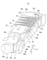
- FIG. 6 is a perspective view illustrating a state in which a sheet drawer is viewed obliquely from the upper front.
- FIG. 6 is a perspective view illustrating a state in which a sheet drawer is viewed obliquely from the lower rear.
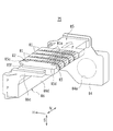
- FIG. 6 is a perspective view illustrating a state in which a sheet drawer is viewed obliquely from the upper rear.
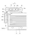
- FIG. 3 is an enlarged cross-sectional view of the paper drawer portion taken along arrows BB in FIG. It is a front view which extracts and shows a suction fan and a separation fan. It is a side view of a suction fan and a separation fan seen from arrow A of Drawing 8A.
- FIG. 6 is a plan view showing a paper drawer portion extracted.
- FIG. 3 is a side view of the paper feeding device shown in FIG. 2. It is sectional drawing which simplifies and shows the paper feeder which concerns on embodiment of this invention.
- FIG. 10 is a cross-sectional view taken along arrow CC in FIG. 9.
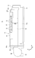
- FIG. 1 is a side view showing a schematic configuration of an image forming apparatus according to an embodiment of the present invention.
- the image forming apparatus 1 includes a document reading unit 2, an image forming unit 11, a paper transport unit 12, a paper supply unit 13, and a large-capacity paper feed cassette (LCC) 14, and uses an image indicated by image data on a paper. Form an image.
- the image forming apparatus 1 reads a document image by the document reading unit 2 to generate image data, or receives image data from an external terminal device or the like. After various image processing is performed on the acquired image data, an image indicated by the image data is formed on a sheet by the image forming unit 11.
- LCC large-capacity paper feed cassette
- the document reading unit 2 is provided above the image forming unit 11 and includes a lower reading optical unit 41 and an upper document conveying unit 42.
- the reading optical unit 41 includes a document placing table 44 and a document reading glass on the upper side, and includes a light source 51 and a solid-state image sensor 48 inside.
- the document table 44 and the document reading glass are formed of transparent glass.
- the surface of the document on the document table 44 or the document reading glass is illuminated by the light source 51, and the reflected light is guided to the solid-state image sensor 48 through a reflection mirror and a lens.
- the solid-state image sensor 48 generates image data based on the received reflected light.
- the document transport unit 42 automatically transports the document on the document reading glass.
- the document conveying unit 42 is configured to be rotatable about an axis connecting the image forming unit 11 and the document conveying unit 42, and the document can be placed manually by opening the document placing table 44. It can be done.
- the image forming unit 11 includes a photosensitive drum 21 and a fixing device 27 along the conveyance path 33, and a charging device 22, a laser exposure device 23, a developing device 24, a transfer roller 25, and a cleaning device around the photosensitive drum 21. 26 is arranged.
- the photosensitive drum 21 has a photosensitive layer on its surface and rotates in the direction of the arrow.
- the surface of the photosensitive drum 21 is cleaned by the cleaning device 26 and then uniformly charged to a predetermined potential by the charging device 22.
- the laser exposure device 23 is a laser scanning unit (LSU) including a laser diode and a reflection mirror, and scans the surface of the photosensitive drum 21 with a laser beam, and an electrostatic latent image corresponding to input image data. Is written on the surface of the photosensitive drum 21.
- the developing device 24 develops the electrostatic latent image written on the surface of the photosensitive drum 21 with toner, and forms a toner image on the surface of the photosensitive drum 21.
- LSU laser scanning unit
- the transfer roller 25 is pressed against the photosensitive drum 21, forms a nip area with the photosensitive drum 21, and rotates together with the photosensitive drum 21.
- the photosensitive drum 21 and the transfer roller 25 sandwich and convey the sheet conveyed through the conveying path 33 in the nip area, and transfer the toner image on the surface of the photosensitive drum 21 to the sheet.
- the sheet on which the toner image is transferred is conveyed to the fixing device 27 through the conveyance path 33.
- the fixing device 27 heats and presses the sheet with a roller or the like to fix the toner image transferred to the sheet. Thereafter, the paper is discharged via a paper discharge roller 36 and stacked on a paper discharge tray 37.
- the paper transport unit 12 includes a plurality of transport rollers 31, registration rollers 32, a transport path 33, a detour path 34, a branch claw 35, a paper discharge roller 36, and a paper discharge tray 37.
- the paper supply unit 13 includes a plurality of paper supply cassettes 38.
- the paper feed cassette 38 includes a pickup roller 39 and the like for pulling out and feeding paper one by one, and sends the paper to the transport path 33.
- the large-capacity paper feed cassette 14 includes a paper feed device 71.
- the sheet feeding device 71 stacks and stores a plurality of sheets, pulls out the sheets one by one, and sends them out to the conveyance path 33. Details of the sheet feeding device 71 will be described with reference to FIG.
- the sheet is conveyed by the conveyance roller 31 through the conveyance path 33, and is discharged to the paper discharge tray 37 via the transfer roller 25 and the fixing device 27.
- the sheet is temporarily stopped by a registration roller 32 provided in front of the photosensitive drum 21, and then the sheet is conveyed in accordance with the transfer timing of the toner image on the surface of the photosensitive drum 21.
- the position of the branch claw 35 is switched and the paper is conveyed from the paper discharge roller 36 to the detour path 34 in the reverse direction.
- the detour path 34 the front and back sides of the paper are reversed and guided again to the registration roller 32, the image is formed on the back side of the paper in the same manner as the front surface, and the paper is discharged to the paper discharge tray 37.
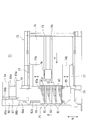
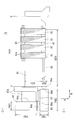
- FIG. 2 is a plan view of the paper feeding device according to the embodiment of the present invention.
- the sheet feeding device 71 has a sheet stacking table 74 on which a plurality of sheets are stacked and moved up and down along a sheet stacking direction S (see FIG. 3 to be described later), and the sheet stacking unit 74 is stacked.
- a sheet conveying member for example, a sheet conveying belt 81
- a separation fan 88 that generates an air flow for separating sheets stacked on the sheet stacking base 74
- a sheet A suction fan 84 that generates a flow of air that sucks the sheets loaded on the loading table 74 and a relay duct 87 that guides the air exhausted from the suction fan 84 to the separation fan 88 are provided.
- the relay duct 87 is formed in a straight line connecting the exhaust port 84 b of the suction fan 84 and the intake port 88 a of the separation fan 88.
- the suction fan 84 acts not only on the force for sucking the paper but also on the force for separating the paper
- the separation fan 88 acts on the force for sucking the paper as well as the force for separating the paper.
- the relay duct 87 in a straight line, a structure having no obstacle such as a wall surface can be provided, and loss when air passes through the relay duct 87 can be reduced. Furthermore, by reducing the number of fans, it is possible to save power and space in the sheet feeding device.
- the sheet feeding device 71 is connected to the suction port 84a of the suction fan 84 and forms a flow path for air that sucks the paper, and the air supply device 71 is connected to the exhaust port 88b of the separation fan 88 and separates the paper. And a separation duct 86 that forms a flow path.
- the paper feeding device 71 includes an outer frame 72, a bottom plate 73, a paper stacking table 74, and a paper drawer 75 disposed on one end of the outer frame 72.
- the paper drawer 75 includes four paper transport belts 81, a set of rollers 82 and 83 around which each paper transport belt 81 is stretched, a suction duct 85, a suction fan 84, a relay duct 87, a separation fan 88, and A separation duct 86 is used.
- the outer frame body 72, the bottom plate 73, and the paper stacking base 74 will be described with reference to FIGS. 2 and 3, and the paper drawing portion 75 will be described later.
- FIG. 3 is a perspective view showing the outer frame, the bottom plate, and the paper stacking base with the paper drawer portion removed.
- the paper stacking board 74 is provided with an opening groove 74a formed long in the paper transport direction H.
- a paper rear end guide 76 is disposed so as to protrude upward through the opening groove 74a.
- the end in the transport direction H of the paper stacked on the paper stacking board 74 may be referred to as the front end, and the end opposite to the transport direction H may be referred to as the rear end.
- the transport direction H may be referred to as the front, and the direction opposite to the transport direction H may be referred to as the rear.
- a direction along the front end of the paper stacked on the paper stacking board 74 is defined as a longitudinal direction N.
- the sheet trailing edge guide 76 includes a guide column portion 76a facing the trailing end of the sheets stacked on the sheet stacking table 74, and a guide head portion 76b supported by the guide column portion 76a.
- the sheet trailing edge guide 76 is supported on the bottom plate 73 so as to reciprocate in the sheet conveying direction H along the opening groove 74a, and is positioned at an arbitrary position.
- loading table recesses 74b are formed, and an assist duct 77 is disposed in each of the loading table recesses 74b.
- the assist duct 77 is supported by the outer frame 72 so as to reciprocate along the longitudinal direction N in the stacking base recess 74b, and the two assist ducts 77 are close to each other or separated from each other. It moves in conjunction and is positioned at any position.
- the outer frame body 72 is arranged so as to surround the sheets stacked on the sheet stacking board 74 in a plan view, and the front end of the sheet is in contact with two frame body opening portions 72a provided on both sides in the longitudinal direction N. And a contact plate 72b.
- a protruding piece 74 c formed on the paper stacking base 74 protrudes outside the outer frame 72 from each frame opening 72 a.
- the contact plate 72b is formed with a notch 72c at a portion facing the first separation port 86b (see FIGS. 5 and 7 described later) of the separation duct 86.
- the assist duct 77 is a hollow body provided with an assist opening 77a on the surface facing the side edge of the paper loaded on the paper stacking board 74, and has a ventilation path inside.
- An assist fan 79 is provided outside each of the two assist ducts 77, and the air sucked by the assist fan 79 is sent into the ventilation path of the assist duct 77, and the outer frame body 72 is formed through the assist opening 77 a. Blows inward.
- winding pulleys 90 are provided at both ends of the outer frame body 72 in the longitudinal direction N, respectively.
- Two wires 93 are respectively connected to the take-up pulley 90, and the wires 93 are connected to protruding pieces 74c corresponding to the side on which the take-up pulley 90 is provided. Further, the wire 93 is drawn around a plurality of driven pulleys 94 and connected to the winding pulley 90. That is, one wire 93 is connected to each of the four protruding pieces 74c.
- the two take-up pulleys 90 are fixed to both ends of a common shaft 91 that is rotatably supported, and the take-up pulley 90 is rotated when the shaft 91 is rotationally driven by a pulse motor 92 connected to the shaft 91.
- the wire 93 is wound around the winding pulley 90 or fed out by rotating forward and reverse.
- the paper stacking table 74 moves up and down in the stacking direction S by winding and unwinding the wire 93. Further, by controlling the rotation direction and rotation angle of the pulse motor 92, the height of the paper stacking base 74 can be adjusted.
- FIG. 4 is a perspective view showing a state in which the paper drawer portion is seen obliquely from the upper front
- FIG. 5 is a perspective view showing a state in which the paper drawer portion is seen from the obliquely lower rear
- FIG. FIG. 7 is a perspective view showing a state in which the paper drawer portion is viewed obliquely from above and rear
- FIG. 7 is an enlarged cross-sectional view mainly showing the paper drawer portion taken along arrows BB in FIG.
- the suction duct 85 is a hollow body and has a long air flow path in the longitudinal direction N as shown in FIG. 4, and through a suction connection portion 85 a provided at the end in the longitudinal direction N.
- a suction fan 84 is connected. Further, the suction duct 85 is disposed along the longitudinal direction N so as to face the upper surface of the paper stacked on the paper stacking table 74, and on the surface facing the upper surface of the paper (the lower surface 85g of the suction duct 85), A plurality of sheet suction ports 85e (see FIG. 7 for details) penetrating to the internal flow path are formed.
- the suction duct 85 is formed with a roller connecting portion 85h protruding at both ends in the transport direction H (front end portion 85c and rear end portion 85d shown in FIG. 4).
- a roller rotation shaft 82a that supports the roller 83 and a roller rotation shaft 83a are connected.
- the roller 82 is supported by the roller rotation shaft 82a, the roller 83 is supported by the roller rotation shaft 83a, and the roller rotation shaft 82a and the roller rotation shaft 83a are connected to a driving means (not shown).
- the paper transport belt 81 is stretched around the rollers 82 and 83 and is not shown, but is slightly separated from the upper surface 85b of the suction duct 85 and is in contact with the lower surface 85g of the suction duct 85. Has been placed.
- the sheet conveying member corresponds to the sheet conveying belt 81.
- a large number of air holes 81 a are formed in the paper conveying belt 81, and air is sucked from the air holes 81 a through the suction duct 85 to the suction fan 84.
- suction fan 84 and the separation fan 88 will be described later with reference to FIGS. 8A and 8B.
- the separation duct 86 is a hollow body, and has a long air flow path in the longitudinal direction N as shown in FIG. 4, and a separation connecting portion 86a (FIG. 2) provided at an end in the longitudinal direction N. Are connected to the separation fan 88. As shown in FIG. 7, the separation duct 86 is disposed to face the front end of the paper stacked on the paper stacking base 74, and is disposed on the surface facing the front end of the paper (the inner wall surface 86 d of the separation duct 86). A first separation port 86b that penetrates to the flow path is formed.
- the inner wall surface 86d is provided so as to overlap the outer surface of the contact plate 72b of the outer frame body 72, and the first separation port 86b faces the inner side of the outer frame body 72 through the cutout portion 72c. Further, the separation duct 86 is formed with a second separation port 86 e opened facing the paper transport belt 81.
- air is sent from the exhaust port 88b of the separation fan 88 to the first separation port 86b and the second separation port 86e through the separation connecting portion 86a, and the first separation port 86b and the first separation port 86b 2 Air is blown out from the separation port 86e to the inside of the outer frame 72. Then, as shown by an arrow K in FIG. 7, the air blown out from the first separation port 86b is sent to the leading edge of the paper stacked on the paper stacking base 74, and several sheets from the top of the stacked paper are removed. To disperse. Here, the sheet loaded on the sheet stacking table 74 is lifted by the air sent from the assist duct 77 (see FIG.
- the air blown out from the second separation port 86e is sent between the plurality of sheets lifted from the sheet stacking table 74, and separates the plurality of sheets one by one. Of the separated sheets, the top sheet is attracted to the sheet transport belt 81, and the remaining sheets are stacked on the sheet stacking board 74.
- the relay duct 87 has a flow path extending along the transport direction H, and has one end connected to the exhaust port 84 b of the suction fan 84. The other end is connected to the intake port 88 a of the separation fan 88. That is, the air blown from the suction fan 84 is sent to the separation fan 88 through the relay duct 87.
- the flow path of the relay duct 87 will be described later with reference to FIG. 8A.
- the relay duct 87 and the separation duct 86 are connected with a predetermined angle, and a separation fan 88 is disposed in the connected portion. According to this configuration, the direction in which air flows through the separation fan 88 is changed, and the separation duct 86 is provided along the air flow from the separation fan 88, thereby reducing loss due to obstacles such as wall surfaces and efficiently.
- the paper can be separated.
- the predetermined angle described above is 80 to 100 degrees, and a preferable angle is 90 degrees. That is, the relay duct 87 and the separation duct 86 are connected at a right angle. According to this configuration, since the air is sent perpendicularly to the intake port 88a of the separation fan 88 by being connected at a right angle, the separation fan 88 can efficiently take in the air.
- a part of the air exhausted from the separation duct 86 is sucked from the suction duct 85.
- a part of the air exhausted from the separation duct 86 is sucked from the suction duct 85, whereby an air flow path is formed between the separation duct 86 and the suction duct 85. Therefore, by circulating the air flowing through the sheet feeding device 71, it is possible to reduce air loss and operate efficiently.
- the end portion (suction tip portion 85f) of the suction duct 85 opposite to the suction connection portion 85a is connected to the end portion (separation tip portion 86c) of the separation duct 86 opposite to the separation connection portion 86a.
- the relay duct 87 is formed separately from the suction duct 85 and the separation duct 86.
- the present invention is not limited to this, and the suction duct 85, the separation duct 86, and the relay are not limited thereto.
- the duct 87 may be integrated. That is, if the flow paths corresponding to the suction duct 85, the separation duct 86, and the relay duct 87 are independently formed, the relay duct 87, the suction connecting portion 85a, The separation connecting portion 86a may be integrated.
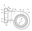
- FIG. 8A is a front view showing the suction fan and the separation fan extracted
- FIG. 8B is a side view of the suction fan and the separation fan as viewed from the arrow A in FIG. 8A
- FIG. It is sectional drawing in the arrow CC.
- the suction fan 84 is a centrifugal fan or the like, for example, a sirocco fan, pressurizes air sucked from the intake port 84a and exhausts it from the exhaust port 84b.
- the suction fan 84 includes a plurality of blades 84c, a fan casing 84d, and a duct portion 84e.
- the separation fan 88 has the same structure as the suction fan 84, and thus the description thereof is omitted.
- the plurality of blades 84c are rotated by driving means (not shown), and send out air outward in the radial direction by the generated centrifugal force.
- a bearing portion 84f is disposed at the center of the intake port 84a, and blades 84c are disposed radially around the bearing portion 84f.
- the plurality of blades 84c are erected on, for example, a disk 84j connected to the rotation shaft 84h.
- a rotating shaft 84h connected to the driving means is disposed, and the disc 84j rotates around the rotating shaft 84h so that the blade 84c rotates.
- the fan casing 84d has a columnar space in which a plurality of blades 84c are accommodated, is formed in a substantially cylindrical shape, and an intake port 84a is provided on a substantially circular main surface 84g.
- the width of the main surface 84g of the fan casing 84d (housing vertical width FW1) is, for example, 120 mm.
- the side surface of the fan casing 84d is partially opened, and the opened portion and the duct portion 84e are connected.
- the width of the side surface of the fan casing 84d (side surface width FW3) is, for example, 33 mm.
- the intake port 84a has a circular shape when viewed from the front, and the diameter (opening diameter FWh) of the intake port 84a is, for example, 80 mm.
- the bearing part 84f mentioned above is formed in the cup shape which protruded toward the main surface 84g, and the diameter (rotary shaft width FWp) of the bearing part 84f is 58 mm, for example.
- the width from the bearing portion 84f to the intake port 84a in the front view may be referred to as an effective opening width FWy. That is, air can be taken into the suction fan 84 by sending air between the bearing portion 84f and the intake port 84a (effective opening width FWy). On the other hand, the air hitting the bearing portion 84f returns without entering the inside of the suction fan 84.
- a region where the suction fan 84 can suck air is referred to as a suction region, and the suction region corresponds to the effective opening width FWy.
- a gap is provided between the blade 84c and the bearing portion 84f.
- the interval between the blade 84c and the bearing portion 84f may be adjusted as appropriate, and a part of the blade 84c is viewed from the front. May be disposed within the effective opening width FWy.
- the duct portion 84e is a hollow tube having a rectangular cross section perpendicular to the air flow direction, and is formed integrally with the fan casing 84d.
- One end portion of the duct portion 84e is connected to the side surface of the fan casing 84d, and the other end portion of the duct portion 84e has an exhaust port 84b that discharges the air that has flowed through the flow path inside the duct portion 84e to the outside.
- the width from the exhaust port 84b to the opposite end of the fan casing 84d (housing lateral width FW2) in front view is, for example, 120 mm.
- the exhaust port 84b is formed in a rectangular shape in a side view, and the opening width (exhaust lateral width VW1) in the rotation axis direction of the exhaust port 84b is, for example, 26 mm.
- the opening width (exhaust length VW2) in the direction orthogonal to the rotation axis 84b is 51 mm, for example. That is, the exhaust port 84b is formed such that the exhaust vertical width VW2 is larger than the exhaust horizontal width VW1.
- the suction fan 84 and the separation fan 88 have the same structure, and include an intake port 88a, an exhaust port 88b, a blade 88c, a fan casing 88d, a duct portion 88e, a bearing portion 88f, a main surface 88g, a rotary shaft 88h,
- the disc 88j corresponds to the intake port 84a, the exhaust port 84b, the blades 84c, the fan casing 84d, the duct portion 84e, the bearing portion 84f, the main surface 84g, the rotating shaft 84h, and the disc 84j of the suction fan 84, respectively.
- the widths of the suction fan 84 and the separation fan 88 are determined by the widths of the fan casing 84d and the duct portion 84e (the casing vertical width FW1, the casing horizontal width FW2, and the side width FW3). Then, the side surface width FW3 is the minimum width, and the rotation axis direction is the minimum width direction of the suction fan 84 and the separation fan 88.
- the wind pressure of the separation fan 88 is set larger than the wind pressure of the suction fan 84. According to this configuration, by increasing the wind pressure of the separation fan 88, it is possible to compensate for the loss that occurs when passing through the relay duct 87. In other words, since the wind pressure slightly decreases due to the length of the flow path, a constant wind pressure is secured by making a difference in the fan output. Specifically, the wind pressure of the suction fan 84 is 200 Pa, and the wind pressure of the separation fan 88 is 380 Pa.
- the duct region DR is formed in a rectangular shape, and has a width of 26 mm in the longitudinal direction N (lateral direction in the drawing) and a width in the stacking direction S (vertical direction in the drawing) of 51 mm. That is, it has the same shape as the exhaust port 84 b of the suction fan 84.
- the duct region DR is preferably formed to be the same as or larger than the exhaust port 84b of the suction fan 84.
- the duct region DR is disposed at a position facing the blade 88c, and is desirably disposed such that the area overlapping with a part of the effective opening width FWy is maximized. That is, when the area where the duct region DR and a part of the effective opening width FWy overlap is maximized, the exhaust port 84b of the suction fan 84 is disposed at a position where the area overlapping the suction region is maximized.
- the air exhausted from the separation fan 88 can be increased by adopting a structure in which as much air sent from the suction fan 84 as possible is taken into the separation fan 88. In other words, the air that is directly sent into the separation fan can be increased by increasing the area opened facing the suction region.
- the area where the exhaust port 84b of the suction fan 84 and the suction region overlap indicates a portion where the exhaust port 84b and the effective opening width FWy overlap when the main surface 88g of the separation fan 88 is viewed from the front.
- the relay duct 87 opens toward the blade 88c of the separation fan 88. According to this configuration, since the air sent from the relay duct 87 directly hits the blades 88c of the separation fan 88, the air can be efficiently sent to the separation fan 88.
- the suction area is annular, and the exhaust port 84b of the suction fan 84 is rectangular. Any one of the exhaust ports 84b of the suction fan 84 projected onto the separation fan 88 is preferably coincident with the tangent of the outer circle of the suction region. According to this configuration, by specifying the position of the exhaust port 84b of the suction fan 84, a structure that maximizes the area overlapping the suction region can be easily designed.
- the long side of the exhaust port 84b of the suction fan 84 is located at a position where the distance in the longitudinal direction N (lateral direction in FIG. 8A) from the exhaust port 88b of the separation fan 88 is maximum (the intake port of the separation fan 88). However, it may be arranged at a position where the distance in the longitudinal direction N from the exhaust port 88b of the separation fan 88 is minimum (the left end of the intake port 88a of the separation fan 88). Further, the long side of the exhaust port 84b of the suction fan 84 is arranged perpendicular to the longitudinal direction N. However, as long as it matches the tangent of the exhaust port 88b of the separation fan 88, It may be inclined.
- the shape of the inlet port 88a of the separation fan 88 and the opening portion of the relay duct 87 are different, only the portion connecting the separation fan 88 and the relay duct 87 is widened to match the inlet port 88a. Thus, it is only necessary to prevent the air sent from the relay duct 87 from leaking to the outside.
- the relay duct 87 is formed so as to cover the main surface 88g, and the air exhausted from the opening of the relay duct 87 is a partial area of the intake port 88a and is opposed to the exhaust port 84b. It is good also as a structure exhausted only.
- FIG. 9 is a plan view showing the paper drawer portion extracted
- FIG. 10 is a side view of the paper feeder shown in FIG.
- the suction duct 85 (excluding the suction connecting portion 85a) has a width KDn in the longitudinal direction N of 455 mm, a width KDh in the transport direction H of 50 mm, and a width KDs in the stacking direction S. (See FIG. 5) is 25 mm. That is, the suction duct 85 is formed long in the longitudinal direction N, and the longitudinal direction N of the suction duct 85 coincides with the longitudinal direction N.
- the separation duct 86 (excluding the separation connecting portion 86a and the separation leading end portion 86c) has a width BDn in the longitudinal direction N of 395 mm, a width BDh in the transport direction H of 33 mm, and a stacking direction.
- the width BDs at S is 65 mm. That is, the separation duct 86 is formed long in the longitudinal direction N, and the longitudinal direction N of the separation duct 86 coincides with the longitudinal direction N. Further, the width BDh in the transport direction H of the separation duct 86 is the minimum width, and the transport direction H is the minimum width direction of the separation duct 86.
- the suction fan 84 is provided with an intake port 84a on a surface perpendicular to the longitudinal direction N and an exhaust port 84b on a surface perpendicular to the transport direction H. That is, since the rotation axis of the suction fan 84 is provided in the longitudinal direction N, the minimum width direction of the suction fan 84 coincides with the longitudinal direction N.
- the separation fan 88 is provided with an intake port 88a on a surface perpendicular to the transport direction H and an exhaust port 88b on a surface perpendicular to the longitudinal direction N. That is, since the rotation axis of the separation fan 88 is provided in the transport direction H, the minimum width direction of the separation fan 88 coincides with the transport direction H.
- the longitudinal direction N of the suction duct 85 matches the minimum width direction of the suction fan 84.
- the separation duct 86 is disposed such that the longitudinal direction N of the suction duct 85 and the longitudinal direction N of the separation duct are parallel to each other, and the conveyance direction H and the minimum width direction of the separation duct 86 coincide with each other.
- the separation fan 88 the minimum width direction of the separation duct 86 and the minimum width direction of the separation fan 88 are arranged in parallel.
- the width in the longitudinal direction N of the paper drawer portion 75 constituted by the duct and the fan can be shortened.
- the minimum width direction of the separation duct 86 and the separation fan 88 coincide with the conveyance direction H, the width in the conveyance direction H at the sheet drawer 75 can be shortened. That is, by reducing the width in the longitudinal direction N and the conveyance direction H as much as possible, the paper feeding device 71 can be made compact.
- the separation fan 88 is provided with an exhaust port 88b on a surface perpendicular to the longitudinal direction N.
- the exhaust port 88b of the separation fan 88 has a width in the stacking direction S (exhaust width VW1) in the transport direction H ( The exhaust vertical width VW2) is formed large. According to this configuration, the cross-sectional area of the flow path can be ensured by widening the exhaust port 88b of the separation fan 88 in the stacking direction S. That is, since the separation fan 88 and the separation duct 86 have the minimum width direction aligned with the conveyance direction H, the width in the conveyance direction H cannot be increased, but the sheet loading table 74 is provided in the stacking direction S. Since the predetermined area is secured, the width can be easily increased.
- the suction fan 84 is provided with an exhaust port 84b on a surface perpendicular to the transport direction H, and the exhaust port 84b of the suction fan 84 has a width in the stacking direction S (a width in the longitudinal direction N (exhaust lateral width VW1)).
- the exhaust vertical width VW2) is formed large. According to this configuration, the cross-sectional area of the flow path can be secured by widening the exhaust port 84b of the suction fan 84 in the stacking direction S. That is, since the suction fan 84 has the minimum width direction aligned with the longitudinal direction N of the suction duct 85, the width in the longitudinal direction N cannot be increased. However, in the stacking direction S, the sheet stacking board 74 is provided. Since the predetermined area is secured, the width can be easily increased.
- the suction duct 85, the relay duct 87, and the separation duct 86 are arranged in a U shape in plan view. Therefore, since the suction duct 85 and the separation duct 86 are extended in the same direction with the relay duct 87 as a base point, the area occupied by the sheet feeding device 71 can be reduced, and space saving can be achieved. Further, a structure in which the suction duct 85 and the separation duct 86 are close to each other can be easily designed, and air can be easily circulated from the separation duct 86 to the suction duct 85.
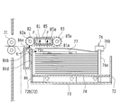
- FIG. 11 is a cross-sectional view schematically showing the paper feeding device according to the embodiment of the present invention.
- the paper is loaded on the paper stacking board 74 and positioned.
- the sheet trailing edge guide 76 is moved backward to widen the gap between the sheet trailing edge guide 76 and the contact plate 72b.
- the assist duct 77 is moved in a direction away from each other to widen the gap between the two assist ducts 77.
- the sheets are stacked on the sheet stacking table 74, the sheet trailing edge guide 76 is moved forward, and the trailing edge of the sheet is pushed in the conveying direction H by the guide pillar portion 76a.
- the sheet pushed by the guide pillar 76a slides and moves on the sheet loading table 74, and the leading end comes into contact with the contact plate 72b.
- the front and rear ends of the paper are sandwiched between the contact plate 72b and the guide post 76a to position the paper.
- the assist duct 77 is moved in a direction approaching each other, and both ends of the sheet in the longitudinal direction N are sandwiched between the two assist ducts 77 to position the sheet.
- the take-up pulley 90 (see FIG. 3) is rotated to raise the paper stacking base 74 and position the paper at a predetermined height. For example, the paper stacking base 74 is raised until the uppermost paper comes into contact with the guide head 76b.
- air is sent into the assist duct 77, and air is blown from the assist duct 77 to the upper layers on both sides of the paper loaded on the paper stacking base 74, thereby causing the paper to rise.
- air is sent from the suction fan 84 and the separation fan 88 to the separation duct 86, and air is blown from the first separation port 86b to the leading edge of the paper so that the paper is dispersed.
- the air blown from the second separation port 86e separates the floated paper.
- the image forming apparatus 1 includes the paper feeding device 71. According to this configuration, by providing the paper feeding device 71 according to the present invention, the same effects as the paper feeding device 71 according to the present invention can be obtained.
Landscapes
- Engineering & Computer Science (AREA)
- Mechanical Engineering (AREA)
- Sheets, Magazines, And Separation Thereof (AREA)
Abstract
L'invention concerne un appareil d'alimentation en papier (71) comprenant : une base d'empilement de papier (74), sur laquelle sont empilées une pluralité de feuilles de papier, et qui est élevée et abaissée dans la direction dans laquelle les feuilles de papier sont empilées ; un élément de transfert de papier (par exemple, une courroie de transfert de papier (81)), qui aspire et transfère les feuilles de papier empilées sur la base d'empilement de papier (74) ; un ventilateur de séparation (88), qui génère un flux d'air en vue de séparer les feuilles de papier empilées sur la base d'empilement de papier (74) ; un ventilateur d'aspiration (84) servant à générer un flux d'air en vue d'aspirer les feuilles de papier empilées sur la base d'empilement de papier (74) ; et un conduit de raccord (87) servant à guider l'air dégagé depuis le ventilateur d'aspiration (84) jusqu'au ventilateur de séparation (88). Le conduit de raccord (87) est d'une forme rectiligne qui relie un orifice de dégagement d'air (84b) du ventilateur d'aspiration (84) et un orifice d'aspiration (88a) du ventilateur de séparation (88).
Priority Applications (2)
| Application Number | Priority Date | Filing Date | Title |
|---|---|---|---|
| US14/373,787 US9079734B2 (en) | 2012-01-27 | 2012-12-20 | Paper feeding device and image forming device |
| CN201280068270.5A CN104080718B (zh) | 2012-01-27 | 2012-12-20 | 供纸装置及图像形成装置 |
Applications Claiming Priority (4)
| Application Number | Priority Date | Filing Date | Title |
|---|---|---|---|
| JP2012014921A JP5818705B2 (ja) | 2012-01-27 | 2012-01-27 | 給紙装置および画像形成装置 |
| JP2012-014922 | 2012-01-27 | ||
| JP2012014922A JP5801213B2 (ja) | 2012-01-27 | 2012-01-27 | 給紙装置および画像形成装置 |
| JP2012-014921 | 2012-01-27 |
Publications (1)
| Publication Number | Publication Date |
|---|---|
| WO2013111483A1 true WO2013111483A1 (fr) | 2013-08-01 |
Family
ID=48873222
Family Applications (1)
| Application Number | Title | Priority Date | Filing Date |
|---|---|---|---|
| PCT/JP2012/083115 Ceased WO2013111483A1 (fr) | 2012-01-27 | 2012-12-20 | Appareil d'alimentation en papier et appareil de formation d'image |
Country Status (3)
| Country | Link |
|---|---|
| US (1) | US9079734B2 (fr) |
| CN (1) | CN104080718B (fr) |
| WO (1) | WO2013111483A1 (fr) |
Cited By (1)
| Publication number | Priority date | Publication date | Assignee | Title |
|---|---|---|---|---|
| US11874623B2 (en) | 2021-03-30 | 2024-01-16 | Kyocera Document Solutions Inc. | Image forming apparatus capable of minimizing number of revolutions of motor |
Families Citing this family (7)
| Publication number | Priority date | Publication date | Assignee | Title |
|---|---|---|---|---|
| JP6105497B2 (ja) * | 2014-01-22 | 2017-03-29 | 東芝テック株式会社 | 給紙装置、剥離補助ユニット、およびプリンタ |
| JP2017014013A (ja) * | 2015-06-26 | 2017-01-19 | 株式会社リコー | プリプレグ搬送装置 |
| TWI624424B (zh) * | 2015-12-16 | 2018-05-21 | 理光股份有限公司 | 片材分離裝置、片材分離方法、程式、影像形成裝置及非暫時性電腦可讀取儲存媒體 |
| CN108099422B (zh) * | 2017-12-27 | 2019-11-01 | 江苏源清环保科技有限公司 | 一种打印机用降落式补纸的纸张补充装置 |
| US10676299B2 (en) * | 2018-04-07 | 2020-06-09 | Roca Robotics, Inc. | Item inventory management system with vacuum operated robotic card sorter |
| JP7204284B2 (ja) * | 2018-11-22 | 2023-01-16 | 理想科学工業株式会社 | 媒体供給装置 |
| JP7552415B2 (ja) * | 2021-02-18 | 2024-09-18 | 京セラドキュメントソリューションズ株式会社 | シート収納装置、およびシート収納装置を備える画像形成ユニット |
Citations (4)
| Publication number | Priority date | Publication date | Assignee | Title |
|---|---|---|---|---|
| JPH10316263A (ja) * | 1997-05-16 | 1998-12-02 | Ricoh Co Ltd | エア分離給送装置 |
| JPH11157678A (ja) * | 1997-11-25 | 1999-06-15 | Ricoh Co Ltd | エアー分離給紙装置の静音化機構 |
| JP2002226068A (ja) * | 2001-01-26 | 2002-08-14 | Duplo Corp | 給紙装置 |
| JP2006213458A (ja) * | 2005-02-03 | 2006-08-17 | Canon Inc | シート給送装置及び画像形成装置 |
Family Cites Families (11)
| Publication number | Priority date | Publication date | Assignee | Title |
|---|---|---|---|---|
| DE3834400A1 (de) * | 1988-10-10 | 1990-04-19 | Heidelberger Druckmasch Ag | Lockerungsblaeser fuer bogenanleger von bogenrotationsdruckmaschinen |
| US6412769B1 (en) | 1999-06-28 | 2002-07-02 | Kyocera Mita Corporation | Paper feeder |
| JP3706277B2 (ja) | 1999-07-30 | 2005-10-12 | 京セラミタ株式会社 | 給紙装置 |
| JP4649340B2 (ja) | 2006-01-20 | 2011-03-09 | キヤノン株式会社 | シート給送装置及び画像形成装置 |
| JP4804186B2 (ja) | 2006-03-28 | 2011-11-02 | キヤノン株式会社 | シート給送装置及び画像形成装置 |
| JP2009190840A (ja) * | 2008-02-14 | 2009-08-27 | Tohoku Ricoh Co Ltd | シート給送装置および印刷装置 |
| JP5272220B2 (ja) * | 2008-05-15 | 2013-08-28 | 株式会社リコー | シート給送装置および画像形成装置 |
| JP2010215350A (ja) * | 2009-03-16 | 2010-09-30 | Konica Minolta Business Technologies Inc | 給紙装置、給紙ユニット及び画像形成システム |
| JP2010247970A (ja) | 2009-04-17 | 2010-11-04 | Konica Minolta Business Technologies Inc | 給紙装置及び画像形成システム |
| CN103072832B (zh) * | 2011-10-26 | 2016-02-17 | 夏普株式会社 | 供纸装置以及具备该供纸装置的图像形成装置 |
| JP5485248B2 (ja) * | 2011-11-17 | 2014-05-07 | シャープ株式会社 | 給紙装置、及びそれを備えた画像形成装置 |
-
2012
- 2012-12-20 WO PCT/JP2012/083115 patent/WO2013111483A1/fr not_active Ceased
- 2012-12-20 CN CN201280068270.5A patent/CN104080718B/zh not_active Expired - Fee Related
- 2012-12-20 US US14/373,787 patent/US9079734B2/en active Active
Patent Citations (4)
| Publication number | Priority date | Publication date | Assignee | Title |
|---|---|---|---|---|
| JPH10316263A (ja) * | 1997-05-16 | 1998-12-02 | Ricoh Co Ltd | エア分離給送装置 |
| JPH11157678A (ja) * | 1997-11-25 | 1999-06-15 | Ricoh Co Ltd | エアー分離給紙装置の静音化機構 |
| JP2002226068A (ja) * | 2001-01-26 | 2002-08-14 | Duplo Corp | 給紙装置 |
| JP2006213458A (ja) * | 2005-02-03 | 2006-08-17 | Canon Inc | シート給送装置及び画像形成装置 |
Cited By (1)
| Publication number | Priority date | Publication date | Assignee | Title |
|---|---|---|---|---|
| US11874623B2 (en) | 2021-03-30 | 2024-01-16 | Kyocera Document Solutions Inc. | Image forming apparatus capable of minimizing number of revolutions of motor |
Also Published As
| Publication number | Publication date |
|---|---|
| CN104080718A (zh) | 2014-10-01 |
| US20140346727A1 (en) | 2014-11-27 |
| CN104080718B (zh) | 2016-05-18 |
| US9079734B2 (en) | 2015-07-14 |
Similar Documents
| Publication | Publication Date | Title |
|---|---|---|
| WO2013111483A1 (fr) | Appareil d'alimentation en papier et appareil de formation d'image | |
| JP5485248B2 (ja) | 給紙装置、及びそれを備えた画像形成装置 | |
| JP5622073B2 (ja) | 給紙装置及び画像形成装置 | |
| JP4804186B2 (ja) | シート給送装置及び画像形成装置 | |
| CN103072832B (zh) | 供纸装置以及具备该供纸装置的图像形成装置 | |
| JP6801313B2 (ja) | 給紙装置及び給紙方法 | |
| JP5818705B2 (ja) | 給紙装置および画像形成装置 | |
| JP5801213B2 (ja) | 給紙装置および画像形成装置 | |
| US20170210579A1 (en) | Feeding device, image forming system, and conveyed medium inspection system | |
| JP5877735B2 (ja) | 給紙装置、及び画像形成装置 | |
| JP5904816B2 (ja) | 給紙装置、及びそれを備えた画像形成装置 | |
| JP6172668B2 (ja) | 給紙装置及び画像形成装置 | |
| JP7490972B2 (ja) | 記録材搬送装置および画像形成装置 | |
| JP5812337B2 (ja) | 給紙装置、及びそれを備えた画像形成装置 | |
| JP5812347B2 (ja) | 給紙装置、及びそれを備えた画像形成装置 | |
| JP2012025491A (ja) | 給紙装置 | |
| JP2013107717A (ja) | 給紙装置、及びそれを備えた画像形成装置 | |
| JP2010215350A (ja) | 給紙装置、給紙ユニット及び画像形成システム | |
| JP5843621B2 (ja) | 給紙装置、及びそれを備えた画像形成装置 | |
| JP6138990B2 (ja) | 給紙装置、及びそれを備えた画像形成装置 | |
| JP2019127379A (ja) | 給紙装置及び画像形成装置 | |
| JP5479433B2 (ja) | 給紙装置、及びそれを備えた画像形成装置 | |
| JP2023164315A (ja) | シート搬送装置及び画像形成システム | |
| JP2007261695A (ja) | シート給送装置及び画像形成装置 | |
| JP2011068477A (ja) | シート搬送機構及びシート搬送機構が組み込まれた画像形成装置 |
Legal Events
| Date | Code | Title | Description |
|---|---|---|---|
| 121 | Ep: the epo has been informed by wipo that ep was designated in this application |
Ref document number: 12866432 Country of ref document: EP Kind code of ref document: A1 |
|
| WWE | Wipo information: entry into national phase |
Ref document number: 14373787 Country of ref document: US |
|
| NENP | Non-entry into the national phase |
Ref country code: DE |
|
| 122 | Ep: pct application non-entry in european phase |
Ref document number: 12866432 Country of ref document: EP Kind code of ref document: A1 |