WO2013111902A1 - パイプライン及びその製造方法 - Google Patents
パイプライン及びその製造方法 Download PDFInfo
- Publication number
- WO2013111902A1 WO2013111902A1 PCT/JP2013/051765 JP2013051765W WO2013111902A1 WO 2013111902 A1 WO2013111902 A1 WO 2013111902A1 JP 2013051765 W JP2013051765 W JP 2013051765W WO 2013111902 A1 WO2013111902 A1 WO 2013111902A1
- Authority
- WO
- WIPO (PCT)
- Prior art keywords
- less
- steel
- steel pipe
- pipeline
- yield strength
- Prior art date
- Legal status (The legal status is an assumption and is not a legal conclusion. Google has not performed a legal analysis and makes no representation as to the accuracy of the status listed.)
- Ceased
Links
Images



Classifications
-
- B—PERFORMING OPERATIONS; TRANSPORTING
- B23—MACHINE TOOLS; METAL-WORKING NOT OTHERWISE PROVIDED FOR
- B23K—SOLDERING OR UNSOLDERING; WELDING; CLADDING OR PLATING BY SOLDERING OR WELDING; CUTTING BY APPLYING HEAT LOCALLY, e.g. FLAME CUTTING; WORKING BY LASER BEAM
- B23K31/00—Processes relevant to this subclass, specially adapted for particular articles or purposes, but not covered by any single one of main groups B23K1/00 - B23K28/00
- B23K31/02—Processes relevant to this subclass, specially adapted for particular articles or purposes, but not covered by any single one of main groups B23K1/00 - B23K28/00 relating to soldering or welding
-
- C—CHEMISTRY; METALLURGY
- C22—METALLURGY; FERROUS OR NON-FERROUS ALLOYS; TREATMENT OF ALLOYS OR NON-FERROUS METALS
- C22C—ALLOYS
- C22C38/00—Ferrous alloys, e.g. steel alloys
- C22C38/001—Ferrous alloys, e.g. steel alloys containing N
-
- C—CHEMISTRY; METALLURGY
- C22—METALLURGY; FERROUS OR NON-FERROUS ALLOYS; TREATMENT OF ALLOYS OR NON-FERROUS METALS
- C22C—ALLOYS
- C22C38/00—Ferrous alloys, e.g. steel alloys
- C22C38/02—Ferrous alloys, e.g. steel alloys containing silicon
-
- C—CHEMISTRY; METALLURGY
- C22—METALLURGY; FERROUS OR NON-FERROUS ALLOYS; TREATMENT OF ALLOYS OR NON-FERROUS METALS
- C22C—ALLOYS
- C22C38/00—Ferrous alloys, e.g. steel alloys
- C22C38/04—Ferrous alloys, e.g. steel alloys containing manganese
-
- C—CHEMISTRY; METALLURGY
- C22—METALLURGY; FERROUS OR NON-FERROUS ALLOYS; TREATMENT OF ALLOYS OR NON-FERROUS METALS
- C22C—ALLOYS
- C22C38/00—Ferrous alloys, e.g. steel alloys
- C22C38/06—Ferrous alloys, e.g. steel alloys containing aluminium
-
- C—CHEMISTRY; METALLURGY
- C22—METALLURGY; FERROUS OR NON-FERROUS ALLOYS; TREATMENT OF ALLOYS OR NON-FERROUS METALS
- C22C—ALLOYS
- C22C38/00—Ferrous alloys, e.g. steel alloys
- C22C38/12—Ferrous alloys, e.g. steel alloys containing tungsten, tantalum, molybdenum, vanadium, or niobium
-
- C—CHEMISTRY; METALLURGY
- C22—METALLURGY; FERROUS OR NON-FERROUS ALLOYS; TREATMENT OF ALLOYS OR NON-FERROUS METALS
- C22C—ALLOYS
- C22C38/00—Ferrous alloys, e.g. steel alloys
- C22C38/14—Ferrous alloys, e.g. steel alloys containing titanium or zirconium
-
- C—CHEMISTRY; METALLURGY
- C22—METALLURGY; FERROUS OR NON-FERROUS ALLOYS; TREATMENT OF ALLOYS OR NON-FERROUS METALS
- C22C—ALLOYS
- C22C38/00—Ferrous alloys, e.g. steel alloys
- C22C38/18—Ferrous alloys, e.g. steel alloys containing chromium
- C22C38/26—Ferrous alloys, e.g. steel alloys containing chromium with niobium or tantalum
-
- C—CHEMISTRY; METALLURGY
- C22—METALLURGY; FERROUS OR NON-FERROUS ALLOYS; TREATMENT OF ALLOYS OR NON-FERROUS METALS
- C22C—ALLOYS
- C22C38/00—Ferrous alloys, e.g. steel alloys
- C22C38/18—Ferrous alloys, e.g. steel alloys containing chromium
- C22C38/28—Ferrous alloys, e.g. steel alloys containing chromium with titanium or zirconium
-
- C—CHEMISTRY; METALLURGY
- C22—METALLURGY; FERROUS OR NON-FERROUS ALLOYS; TREATMENT OF ALLOYS OR NON-FERROUS METALS
- C22C—ALLOYS
- C22C38/00—Ferrous alloys, e.g. steel alloys
- C22C38/18—Ferrous alloys, e.g. steel alloys containing chromium
- C22C38/38—Ferrous alloys, e.g. steel alloys containing chromium with more than 1.5% by weight of manganese
-
- F—MECHANICAL ENGINEERING; LIGHTING; HEATING; WEAPONS; BLASTING
- F16—ENGINEERING ELEMENTS AND UNITS; GENERAL MEASURES FOR PRODUCING AND MAINTAINING EFFECTIVE FUNCTIONING OF MACHINES OR INSTALLATIONS; THERMAL INSULATION IN GENERAL
- F16L—PIPES; JOINTS OR FITTINGS FOR PIPES; SUPPORTS FOR PIPES, CABLES OR PROTECTIVE TUBING; MEANS FOR THERMAL INSULATION IN GENERAL
- F16L13/00—Non-disconnectable pipe joints, e.g. soldered, adhesive, or caulked joints
- F16L13/02—Welded joints
-
- F—MECHANICAL ENGINEERING; LIGHTING; HEATING; WEAPONS; BLASTING
- F16—ENGINEERING ELEMENTS AND UNITS; GENERAL MEASURES FOR PRODUCING AND MAINTAINING EFFECTIVE FUNCTIONING OF MACHINES OR INSTALLATIONS; THERMAL INSULATION IN GENERAL
- F16L—PIPES; JOINTS OR FITTINGS FOR PIPES; SUPPORTS FOR PIPES, CABLES OR PROTECTIVE TUBING; MEANS FOR THERMAL INSULATION IN GENERAL
- F16L13/00—Non-disconnectable pipe joints, e.g. soldered, adhesive, or caulked joints
- F16L13/02—Welded joints
- F16L13/04—Welded joints with arrangements preventing overstressing
-
- B—PERFORMING OPERATIONS; TRANSPORTING
- B23—MACHINE TOOLS; METAL-WORKING NOT OTHERWISE PROVIDED FOR
- B23K—SOLDERING OR UNSOLDERING; WELDING; CLADDING OR PLATING BY SOLDERING OR WELDING; CUTTING BY APPLYING HEAT LOCALLY, e.g. FLAME CUTTING; WORKING BY LASER BEAM
- B23K2101/00—Articles made by soldering, welding or cutting
- B23K2101/04—Tubular or hollow articles
- B23K2101/10—Pipe-lines
-
- Y—GENERAL TAGGING OF NEW TECHNOLOGICAL DEVELOPMENTS; GENERAL TAGGING OF CROSS-SECTIONAL TECHNOLOGIES SPANNING OVER SEVERAL SECTIONS OF THE IPC; TECHNICAL SUBJECTS COVERED BY FORMER USPC CROSS-REFERENCE ART COLLECTIONS [XRACs] AND DIGESTS
- Y10—TECHNICAL SUBJECTS COVERED BY FORMER USPC
- Y10T—TECHNICAL SUBJECTS COVERED BY FORMER US CLASSIFICATION
- Y10T428/00—Stock material or miscellaneous articles
- Y10T428/12—All metal or with adjacent metals
Definitions
- the present invention relates to a pipeline having a plurality of welded portions in which ends of a plurality of steel pipes are joined to each other by welding, and a manufacturing method thereof.
- Patent Documents 1 and 2 disclose a method for preventing softening of a heat affected zone of girth welding.
- Patent Document 3 discloses a method for reducing the yield ratio of a steel pipe.
- Patent Document 4 discloses a method for limiting shape irregularities at a girth weld.
- Japanese Patent Laid-Open No. 3-133576 Japanese Laid-Open Patent Publication No. 3-2111255 Japanese Patent Laid-Open No. 2001-192773 Japanese Unexamined Patent Publication No. 2006-281217
- an object of the present invention is to provide a pipeline that sufficiently exhibits the deformation characteristics of a steel pipe (line pipe).
- the pipeline indicates a structure in which a plurality of steel pipes (line pipes) are joined.
- buckling may occur in the vicinity of the welded portion of the weld joint where the steel pipe and the steel pipe are joined. It has been found that this buckling occurs not only in the part affected by heat due to welding but also in the base metal part which is a part not affected by heat in the welded joint part.
- a pipeline In general, a pipeline is often laid over several kilometers or more. The amount that can be manufactured by one melting is at most about 300 tons, and therefore, a pipeline usually includes a steel pipe manufactured from a plurality of molten steels. Even in the case of steel melted aiming at the same chemical composition, the ratio of each alloy element varies within the target range. That is, there is a variation between the melting charges of chemical components.
- the rolling conditions are hardly the same among a plurality of steel pipes. Therefore, there is usually a certain range of strength differences between the steel pipes used in the pipeline, even if they correspond to the same standard.
- the present inventors pay attention not only to the yield ratio that represents the work hardening characteristics of the material, but also to the difference in strength of the steel pipes facing each other at the girth welds.
- the effect of deformation on the wrinkles that is, the distance between the spool surface and the arc edge of the steel pipe at the time when buckling begins to occur, was studied intensively.
- the present invention has been devised based on the above findings, and the gist is as follows.
- the pipeline which concerns on 1 aspect of this invention is a pipeline which has the some weld part by which the edge parts of the some steel pipe were joined by welding, Comprising: 1 or more types of these steel pipes Manufactured from a plurality of charged molten steels having the following steel components; the stress-strain curve obtained when stress is applied in the longitudinal direction of each steel pipe has no yield point elongation; the pipe thickness of each steel pipe T of unit mm and D of unit mm which is an average pipe diameter satisfy the following formula (a); in the plurality of welds, the yield strength of one steel pipe welded to each other and the yield strength of the other steel pipe And YR indicating the yield ratio, which is the ratio of the yield strength to the tensile strength of the steel pipe with the lower yield strength among the one steel pipe and the other steel pipe, Formula (b) is satisfied.
- t / D 100 ⁇ 6 (a) ⁇ YS ⁇ ⁇ 1.75 ⁇ YR + 230 (b)
- the steel component is mass%, C: 0.04% to 0.15%, Mn: 1.0% to 1.75%, Nb : 0.005% to 0.10%, Ti: 0.005% to 0.02%, Al: 0.001% to 0.06%, Si: 0.4% or less, P : 0.015% or less, S: 0.005% or less, N: 0.007% or less, the balance is composed of Fe and unavoidable impurities, between the one steel pipe and the other steel pipe,
- the ⁇ Ceq value which is the absolute value of the difference between the Ceq values represented by the following formula (c), may be 0.045% or less, and the tensile strength of the plurality of steel pipes may be 450 MPa or more and 850 MPa or less.
- Ceq [C] + [Mn] / 6 (c)
- [C] and [Mn] indicate the content of C and Mn in mass%.
- the steel component is, in mass%, Cu: 0.1% or more and 1.0% or less, Ni: 0.1% or more and 1.0% or less. Cr: 0.1% or more and 1.0% or less, Mo: 0.05% or more and 0.3% or less, V: 0.01% or more and 0.1% or less, and ⁇ Ceq
- the value may be represented by formula (d).
- Ceq [C] + [Mn] / 6 + ([Ni] + [Cu]) / 15 + ([Cr] + [Mo] + [V]) / 5 (d)
- [C], [Mn], [Ni], [Cu], [Cr], [Mo], and [V] are C%, Mn, Ni, Cu, Cr, Mo, and V in mass%. Indicates the content.
- a pipeline according to another aspect of the present invention is a pipeline having a plurality of welds in which ends of a plurality of steel pipes are joined by welding, and the plurality of steel pipes is one or more types.
- t and D in unit mm which is an average pipe diameter satisfy the following formula (e); in the plurality of welds, the difference between the yield strength of one steel pipe welded to the other and the yield strength of the other steel pipe ⁇ YS of unit MPa, and YR indicating the yield ratio, which is the ratio of the yield strength to the tensile strength of the steel pipe having the lower yield strength among the one steel pipe and the other steel pipe, is represented by the following formula (f ) Is satisfied.
- t / D 100 ⁇ 6 (e) ⁇ YS ⁇ ⁇ 0.69 ⁇ YR + 125 (f)
- the steel component is mass%, C: 0.04% to 0.15%, Mn: 1.0% to 1.75%, Nb : 0.005% to 0.05%, Ti: 0.005% to 0.02%, Al: 0.001% to 0.06%, Si: 0.4% or less, P : 0.015% or less, S: 0.005% or less, N: 0.007% or less, the balance is made of Fe and unavoidable impurities, and between the one steel pipe and the other steel pipe.
- the ⁇ Ceq value which is the absolute value of the difference between the Ceq values represented by the following formula (g), is 0.045% or less, the tensile strength of the plurality of steel pipes is 450 MPa or more and 850 MPa or less, A heat-processable resin may be coated on the front and back surfaces of the steel pipe.
- Ceq [C] + [Mn] / 6 (g)
- [C] and [Mn] indicate the content of C and Mn in mass%.
- the steel component further includes, by mass, Cu: 0.1% to 1.0%, Ni: 0.1% to 1.0%. Cr: 0.1% or more and 1.0% or less, Mo: 0.05% or more and 0.3% or less, V: 0.01% or more and 0.1% or less, and ⁇ Ceq
- Ceq [C] + [Mn] / 6 + ([Ni] + [Cu]) / 15 + ([Cr] + [Mo] + [V]) / 5 (h)
- [C], [Mn], [Ni], [Cu], [Cr], [Mo], and [V] are C%, Mn, Ni, Cu, Cr, Mo, and V in mass%. Indicates the content.
- the steel components are in mass%, C: 0.04% to 0.15%, Mn: 1.0% to 1.75%, Nb : 0.005% to 0.05%, Ti: 0.005% to 0.02%, Al: 0.001% to 0.06%, Si: 0.4% or less, P : 0.015% or less, S: 0.005% or less, N: 0.007% or less, the balance is made of Fe and unavoidable impurities, and between the one steel pipe and the other steel pipe
- the ⁇ Ceq value which is the absolute value of the difference between the Ceq values represented by the following formula (i), may be 0.045% or less, and the tensile strength of the plurality of steel pipes may be 450 MPa or more and 850 MPa or less.
- Ceq [C] + [Mn] / 6 (i)
- [C] and [Mn] indicate the content of C and Mn in mass%.
- the steel component is, in mass%, Cu: 0.1% or more and 1.0% or less, Ni: 0.1% or more and 1.0% or less. Cr: 0.1% or more and 1.0% or less, Mo: 0.05% or more and 0.3% or less, V: 0.01% or more and 0.1% or less, and ⁇ Ceq
- the value may be represented by formula (j).
- Ceq [C] + [Mn] / 6 + ([Ni] + [Cu]) / 15 + ([Cr] + [Mo] + [V]) / 5 (j)
- [C], [Mn], [Ni], [Cu], [Cr], [Mo], and [V] are C%, Mn, Ni, Cu, Cr, Mo, and V in mass%. Indicates the content.
- a method for manufacturing a pipeline according to one aspect of the present invention is the method for manufacturing the pipeline according to claim 1, wherein the first yield strength measurement is performed to measure the yield strength of the plurality of steel pipes.
- a method for manufacturing a pipeline according to another aspect of the present invention is a method for manufacturing a pipeline according to claim 1, wherein the plurality of steel pipes are rolled with serial numbers capable of specifying each.
- a first numbering step that is applied in the order in which they are performed;
- a second welding step of welding steel pipes that are manufactured from the same molten steel and the same hot-rolled coil and that have a difference between the manufacturing numbers of 1 to 5 And having;
- a method of manufacturing a pipeline according to another aspect of the present invention is the method of manufacturing a pipeline according to claim 4, wherein the second yield of the yield strength of the plurality of steel pipes is measured.
- a method for manufacturing a pipeline according to another aspect of the present invention is a method for manufacturing a pipeline according to claim 4, wherein the manufacturing numbers that can identify each of the plurality of steel pipes are rolled.
- a second numbering step that is applied in the order that they are performed; and a fourth welding step that welds steel pipes that are manufactured from the same molten steel and that have a difference in the manufacturing number of 1 to 5 inclusive.
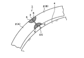
- the pipeline 1 has a joint structure in which ends of a plurality of steel pipes 2 are joined together by welding.
- a steel pipe A one steel pipe 2 of the joint structure whose ends are welded to each other
- a steel pipe B one steel pipe 2 of the joint structure whose ends are welded to each other
- the steel pipe A and the steel pipe B are joined at the welded portion 3 by abutting the end portions to each other and being welded all around.
- the pipeline according to the present embodiment is elongated by joining a plurality of steel pipes as described above.
- the pipeline 1 When the pipeline 1 according to the present embodiment is laid on the sea floor by the spool method, as shown in FIG. 1, the pipeline 1 is wound around the drum 4 and transported to the laid sea, and is rewound at the site and piped to the sea floor. Lay down line 1.
- the maximum compressive strain is generated in the longitudinal direction of the pipeline 1 (steel pipe 2) at the inner arc edge that is the innermost position of the winding.
- a maximum tensile strain is generated in the longitudinal direction of the pipeline 1 (steel pipe 2).
- buckling may occur at the inner arc edge in the vicinity of the base metal part of the welded joint part, particularly in the vicinity of the heat affected zone (HAZ) 5 of the welded part 3.
- HZ heat affected zone
- the present inventors perform numerical analysis using FEA (Finite Element Analysis). A simulation was attempted.
- the yield ratio YR of the steel pipe A and the steel pipe B was set to 85%, 92.5%, 95%, and 98%.
- the difference ⁇ YS between the yield strength of the steel pipe A and the yield strength of the steel pipe B was set to 0 MPa, 50 MPa, 75 MPa, and 100 MPa. And it analyzed about the combination of each yield ratio YR and each yield strength difference (DELTA) YS.
- the pipeline 1 (steel pipe 2) is wound around the drum 4, due to the compressive strain generated in the heat-affected zone inside the winding and the tensile strain generated in the heat-affected zone outside the winding, In the welded portion 3, the pipeline 1 (steel pipe 2) may be lifted from the outer surface of the drum 4. In this case, a gap ⁇ C is generated between the inner arc edge (inner surface) of the pipeline 1 (steel pipe 2) and the outer surface of the drum 4.
- the inventors focused on the gap ⁇ C and studied buckling occurring at the inner arc edge.
- the present inventors set the maximum strain ⁇ max generated in the gap ⁇ C and the inner arc edge. And observed the relationship. As a result, as shown in FIG. 2, regardless of the magnitude (combination) of the yield ratio YR and the yield strength difference ⁇ YS, when the gap ⁇ C exceeds 20 mm, the value of the gap ⁇ C increases rapidly, that is, local buckling. The knowledge that occurs is obtained.
- the limit value of the gap ⁇ C at which buckling occurs is a steel pipe (a so-called “round type” steel pipe) in which no yield point elongation appears in the stress-strain curve (SS curve) obtained when stress is applied in the longitudinal direction.
- SS curve stress-strain curve
- YPE type steel pipe
- the local buckling distortion was larger in the round type than in the YPE type, and it was also found that buckling is difficult.
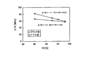
- FIG. 3 shows the relationship between the yield ratio YR and the yield strength difference ⁇ YS of the steel pipe (A or B) having the lower yield strength among the steel pipe A and the steel pipe B.
- the relationship between the yield ratio YR and the yield strength difference ⁇ YS is different between the round type steel pipe and the YPE type steel pipe. That is, the graph of FIG.
- the steel pipes facing each other satisfy the above-described relationship (equation (b) if the steel pipe is a round type, and formula (f) if the steel pipe is a YPE type. Regardless of the composition and strength of the steel pipe, local buckling can be prevented.
- characteristics suitable for actual use for example, characteristics satisfying X42 to X80 specified in API (American Petroleum Institute) SPECIFICATION 5L
- the steel pipe according to the present embodiment The range of preferable chemical components in the steel pipe used in the pipeline according to the present embodiment (hereinafter sometimes referred to as the steel pipe according to the present embodiment) will be described.
- the molten steel of a some charge is used in a pipeline, it is preferable that it is the following ranges in all the molten steel. “%” Of the content of each element means “mass%”.
- C 0.04% or more, 0.15% or less C is an element that contributes to strengthening of steel (steel pipe), and preferably contains 0.04% or more.
- the upper limit is preferably made 0.15%.
- a more preferable range is 0.05% or more and 0.10% or less.
- Mn 1.0% or more and 1.75% or less
- Mn is an element that enhances hardenability and contributes to toughening of steel, and the content is preferably 1.0% or more.
- Mn is an element that easily segregates, and if contained excessively, coarse MnS may be generated at the central portion of the plate thickness, which may impair the characteristics. Therefore, the upper limit of the Mn content is preferably 1.75%. A more preferable range is 1.0% or more and 1.6% or less.
- Nb 0.005% or more, 0.10% or less
- Nb is hot-rolled while being hot-rolled while being hot-rolled (in a state in which no subsequent steps such as heat treatment are performed after hot-rolling). It is an element that facilitates atomization. Moreover, it is an element which produces carbonitride and contributes to refinement
- Ti 0.005% or more and 0.02% or less Ti is an element that generates nitrides, fixes N, and contributes to refinement and strengthening of the structure. In order to obtain these effects, the Ti content is preferably 0.005% or more. On the other hand, when Ti is added excessively, coarse TiN is generated, and the characteristics may be impaired. Therefore, it is preferable to make the upper limit of the Ti content 0.02%.
- Al 0.001% or more and 0.06% or less
- Al is an element effective as a deoxidizer.
- the Al content is preferably 0.001% or more.
- Al content shall be 0.001% or more and 0.06% or less.
- a more preferable lower limit of the Al content is 0.01% or more.
- Si 0.4% or less Si is an element used for deoxidation and strengthening of steel. However, if contained excessively, an embrittled phase may be generated in the weld heat affected zone. Therefore, it is preferable to limit the Si amount to 0.4% or less.
- the Si content may be 0%.
- P 0.015% or less
- P is an impurity, and may segregate at grain boundaries to deteriorate the characteristics. Therefore, the content is preferably limited to 0.015% or less.
- the P content may be 0%.
- S 0.005% or less Since S is an impurity and may cause sulfides such as MnS to deteriorate characteristics, it is preferable to limit the S content to 0.005% or less.
- the S content may be 0%.
- N 0.007% or less
- N is an element that forms a nitride such as TiN, and fine TiN is used to refine the structure. However, when it contains excessively, a coarse nitride will be produced and a characteristic will be degraded. Therefore, the N content is preferably limited to 0.007% or less. The N content may be 0%.
- the steel pipe according to the present embodiment may further contain Cu, Ni, Cr, Mo, and V that contribute to strengthening in the following ranges as necessary. Since these chemical elements do not necessarily need to be added to the steel sheet, the lower limits of these chemical elements are all 0% and are not limited.
- Cu 0.1% or more and 1.0% or less Cu is an element that enhances the hardenability of the steel and increases the strength of the steel. In order to acquire the effect, it is preferable to make it contain 0.1% or more. However, if the Cu content exceeds 1.0%, weldability may be deteriorated or surface cracking of the steel may occur during rolling. Therefore, the Cu content is limited to 1.0% or less. More preferably, it is 0.95% or less, More preferably, it is 0.5% or less, 0.2% or less.
- Ni 0.1% or more and 1.0% or less
- Ni is an element that increases the hardenability of the steel to increase the strength of the steel and contributes to the improvement of low temperature toughness. In order to acquire the effect, it is preferable to make it contain 0.1% or more. However, if the Ni content exceeds 1.0%, weldability may be reduced, so the Ni content is limited to 1.0% or less. More preferably, it is 0.5% or less, and further preferably 0.3% or less.
- Cr 0.1% or more and 1.0% or less Cr is an element that enhances the hardenability of the steel and increases the strength of the steel. In order to acquire the effect, it is preferable to make it contain 0.1% or more. However, if the Cr content exceeds 1.0%, the weldability may be reduced. Therefore, the addition amount is limited to 1.0% or less. More preferably, it is 0.5% or less.
- Mo 0.05% or more and 0.3% or less Mo is an element that increases the hardenability of the steel to increase the strength of the steel and contributes to the improvement of low-temperature toughness. In order to acquire the effect, it is preferable to make it contain 0.05% or more. However, if the Mo content exceeds 0.3%, a large amount of low-temperature transformation phase may be generated or precipitation hardening may occur excessively, resulting in deterioration of low-temperature toughness. Therefore, the upper limit of the Mo content is limited to 0.3%. A preferable upper limit of the Mo content is 0.2%.
- V 0.01% or more and 0.1% or less V is an element having an effect similar to that of Nb, but its influence is smaller than that of Nb. In order to acquire the effect, it is preferable to make it contain 0.01% or more. Even if the V content exceeds 0.1%, the effect is saturated and the cost increases, so the upper limit is limited to 0.1%.
- the effect is not impaired.
- elements other than the above for example, Zr, Sn, Co, As, etc.
- Cu, Ni, Cr, Mo, and V are contained below the lower limit, they are treated as inevitable impurities.
- a steel pipe used for a pipeline is generally manufactured from a plurality of molten steels. Therefore, one steel pipe and the other steel pipe welded to each other are often manufactured from different molten steels.
- the yield strength is greatly affected by chemical components, particularly Ceq represented by the following formula. Therefore, when ⁇ YS, which is the difference in yield strength, is reduced, it is effective to reduce ⁇ Ceq, which is the absolute value of the difference in Ceq, between one steel pipe and the other steel pipe.
- ⁇ Ceq value is decreased, ⁇ TS is decreased.
- ⁇ Ceq is preferably 0.045 or less. More preferably, it is 0.035 or less.
- the manufacturing method of the pipeline which concerns on embodiment of this invention is demonstrated.
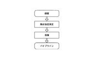
- the yield strength of each steel pipe is measured before joining each other by welding for a plurality of steel pipes used in the pipeline. Then, based on the measurement result of the yield strength, the steel pipe showing the round SS curve satisfies the above formula (b), and the steel pipe showing the YPE SS curve satisfies the above formula (f).
- one steel pipe to be welded and the other steel pipe may be selected and welded. According to this method, it is possible to reliably weld steel pipes having a small ⁇ YS, which is a difference in yield strength, regardless of the steel pipe components and the history of manufacturing conditions.
- all the steel pipes used in the pipeline are assigned production numbers that can identify them in the rolling order (for example, X + 1, X + 2,..., X + N, etc. in the rolling order). And what is necessary is just to weld the steel pipes manufactured from the same molten steel and the same hot-rolled coil, and the difference of the said serial numbers is 1-5.
- the steel pipes with a large difference in the assigned manufacturing numbers have different cooling conditions when wound on the coil. There may be significant differences. Therefore, it is preferable to weld steel pipes manufactured from the same molten steel and the same hot-rolled coil and having a difference in the serial number of 1 to 5 inclusive.
- the production number is given after the steel pipe has been formed. However, this production number can be used when rolling the steel sheet as the material of the steel pipe if the rolling order is clear. Alternatively, it may be applied at any stage, such as during cooling or when creating a rolling plan.
- the manufacturing method of the steel pipe used for the pipeline according to the present embodiment is not particularly limited, and is manufactured according to a conventional method according to desired characteristics. do it. However, when obtaining a steel pipe having characteristics suitable for actual use (for example, characteristics satisfying API Specification 5L X42 to X80), for example, the following manufacturing method should be adopted. Thus, round type and YPE type steel pipes can be easily manufactured.
- ERW steel pipe having a tensile strength of 450 MPa or more and 850 MPa or less and an SS curve showing a round shape
- the slab having the above-described preferred range of chemical components is heated to 1200 ° C. or more and 1300 ° C. or less, and the heated slab is roughly rolled to obtain a steel material.
- the steel material is subjected to finish rolling at a rolling end temperature of 800 ° C. or higher and 900 ° C. or lower. After completion of finish rolling, the steel material is cooled from a temperature range of 780 ° C. or higher to a temperature range of 400 ° C.
- the cooled steel material is wound into a hot rolled coil in a temperature range of 400 ° C. or higher and 580 ° C. or lower. After this hot-rolled coil is cooled to room temperature, an open tube is formed by roll forming while unwinding the hot-rolled coil. The seam portion of the open pipe is welded by electric resistance welding, and the electric resistance welding portion is subjected to seam heat treatment, whereby a round type electric resistance steel pipe can be obtained.
- the cooled steel material is air-cooled to room temperature to obtain a steel plate.
- a round UOE steel pipe can be obtained. If a method like the above (i) or (ii) is used, a round type steel pipe having a tensile strength of 450 MPa to 850 MPa can be stably produced.
- the SS curve is assumed to be a round shape because there is distortion due to cold forming while the pipe is still formed.
- the hot-rolled coil is subjected to ERW molding according to a conventional method to produce a pipe.
- heat treatment such as quenching and tempering (QT), tempering (T), or aging treatment after ERW molding, a YPE-type ERW steel pipe can be obtained.
- QT quenching and tempering
- T tempering
- aging treatment after ERW molding, a YPE-type ERW steel pipe can be obtained.
- thermosetting resin coating is performed, for example, by heating a steel pipe to a temperature range of 200 ° C. to 250 ° C. with a ring-shaped induction heater or the like, and spraying a thermosetting resin such as an epoxy resin with the spray in the temperature range. ,It can be carried out.
- round type steel pipes manufactured by methods such as (i) and (ii) are heated to a temperature range of about 200 ° C. to 250 ° C. and maintained at this temperature range for 10 minutes or more to cause strain aging.
- a YPE type steel pipe can be obtained. This is considered to be because interstitial solid solution elements such as C and N adhere to dislocations in the steel material as time passes.
- the coating of the heat-processable resin and the aging treatment are treatments for heating the steel pipe to the same temperature range, the influence on the mechanical properties of the steel pipe is almost equivalent.
- ERW steel pipe (ERW steel pipe) has high productivity and can be manufactured at low cost.
- the seamless steel pipe is characterized in that a high t / D steel pipe is easy to manufacture.
- the present invention will be further described with reference to examples.
- the conditions of an Example are one condition examples employ
- the present invention can adopt various conditions as long as the object of the present invention is achieved without departing from the gist of the present invention.
- This test apparatus 10 has a bending bed 11 and a bending bed 12 arranged one above the other.
- the lower surface of the bending return bed 11 has a downwardly convex curved surface
- the upper surface of the bending bed 12 has an upwardly convex curved surface.
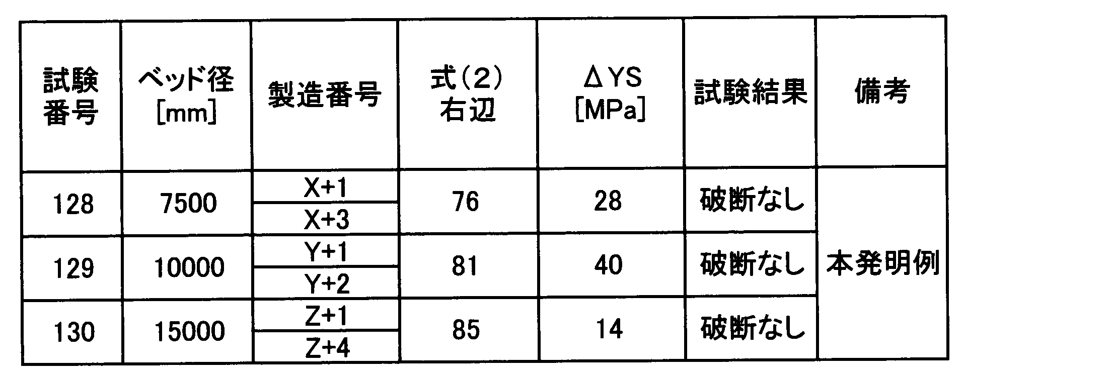
- the end part opposite to the welded part 3 of the steel pipe A is used for bending back. It fixes between the lower surface of the bed 11 and the upper surface of the bed 12 for bending. Then, a bending load 13 is applied to the end of the steel pipe B opposite to the weld 3.
- the steel pipes A and B are bent along the upper surface of the bending bed 12 by applying the bending load 13 downward. Thereby, the load of the same conditions as the case where it winds around a drum with respect to the steel pipes A and B is added.
- the steel pipes A and B are bent along the lower surface of the return bed 11. Thereby, the load of the same conditions as what is called bending back which extends the curved steel pipes A and B linearly is added.
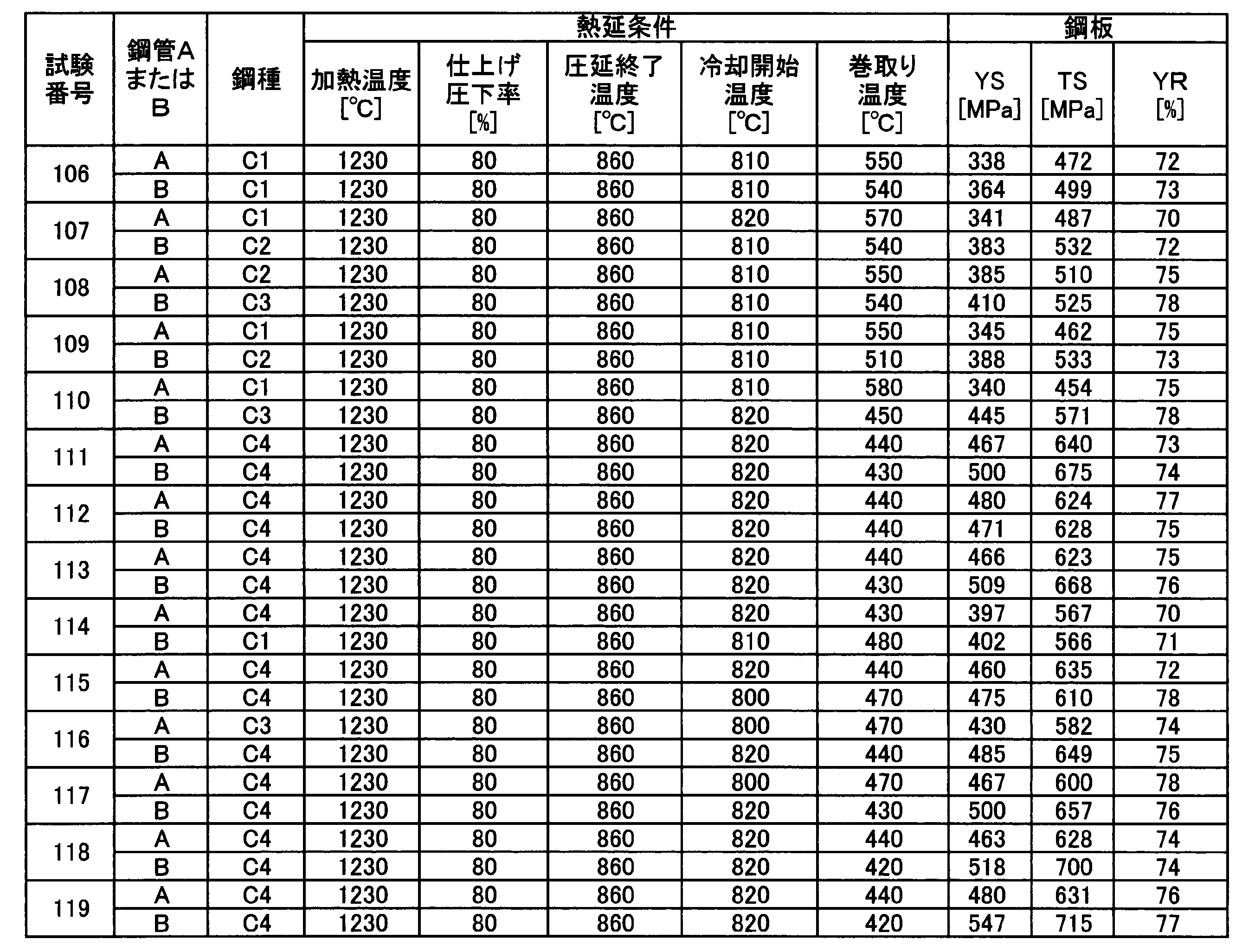
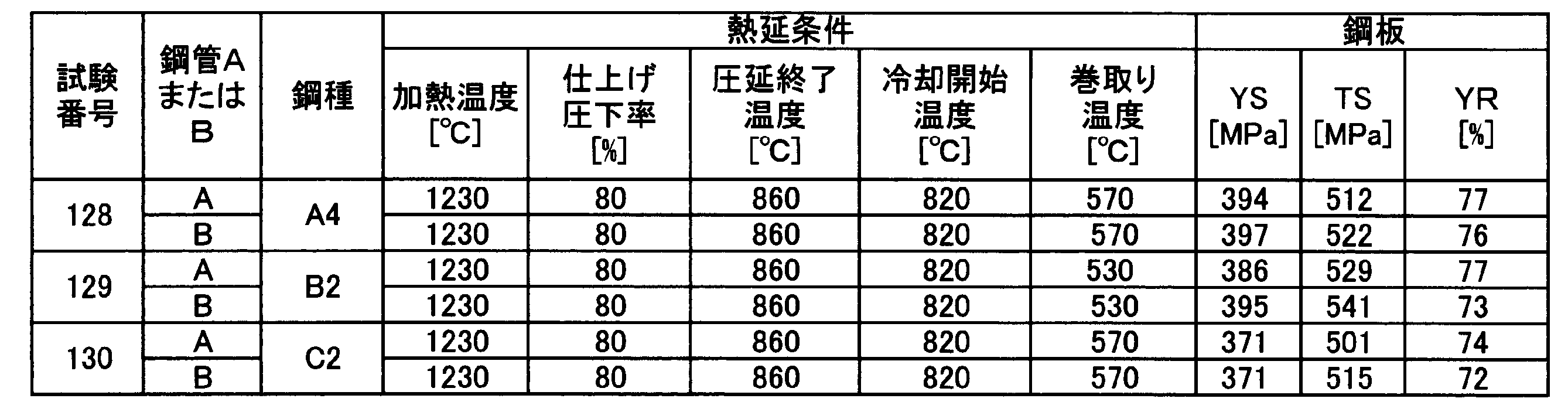
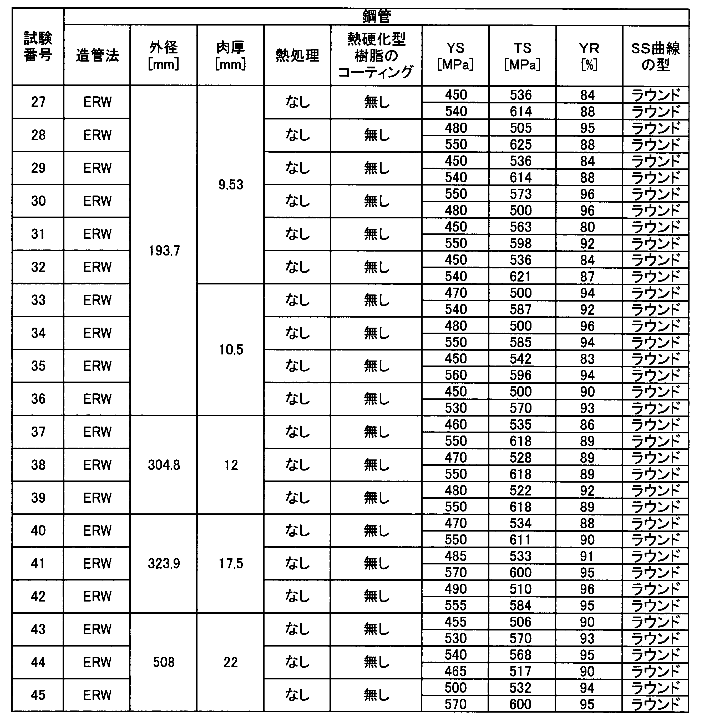
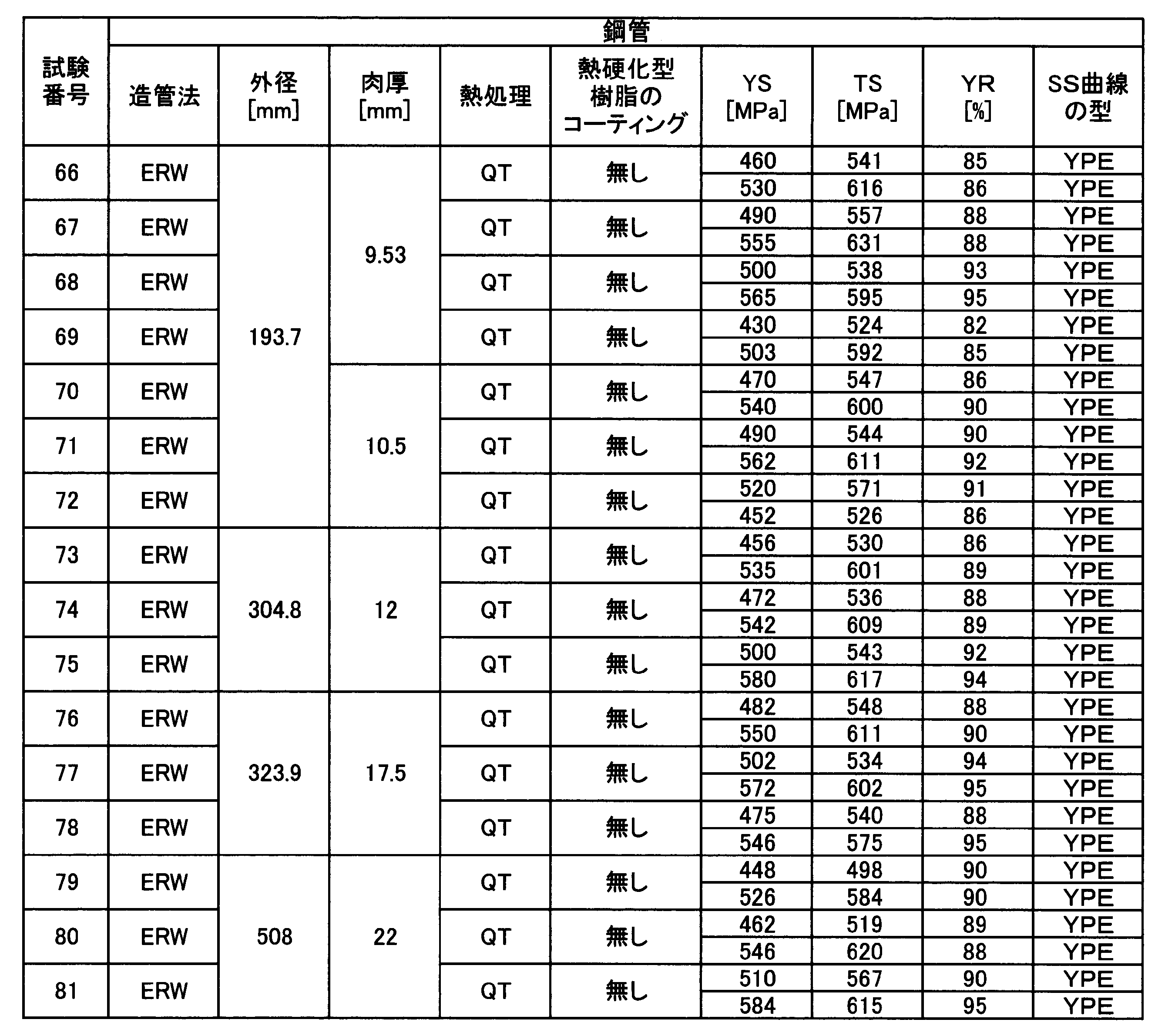
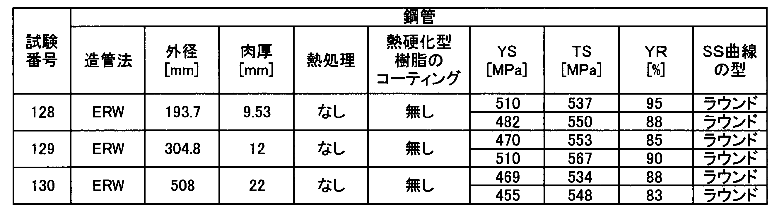
- the aging treatment in Table 15 indicates that the steel pipe was heated to 200 ° C. and held in that temperature range for 10 minutes. Tempering in Table 15 indicates that the steel pipe was heated to 600 ° C. QTs in Tables 13 and 14 indicate that a quenching treatment in which water is cooled after heating to 930 ° C. and a tempering treatment in which heating is performed to 650 ° C. are performed.
- the thermosetting resin coating was performed by heating the steel pipe to a temperature range of 200 ° C. to 250 ° C. with a ring-shaped induction heater or the like and spraying the epoxy resin with a spray or the like in that temperature range.
- the tensile test of the steel plate and the steel pipe was performed according to the full thickness tensile test method defined in API Specification 5L.
- a bending load 13 is applied downward to bend the steel pipes A and B.
- the operation and the operation of applying bending load load 13 upward and applying bending back to steel pipes A and B were repeated three times alternately.
- ⁇ YS is a round type.
Landscapes
- Chemical & Material Sciences (AREA)
- Engineering & Computer Science (AREA)
- Mechanical Engineering (AREA)
- Materials Engineering (AREA)
- Metallurgy (AREA)
- Organic Chemistry (AREA)
- General Engineering & Computer Science (AREA)
- Heat Treatment Of Steel (AREA)
- Butt Welding And Welding Of Specific Article (AREA)
- Heat Treatment Of Articles (AREA)
- Arc Welding In General (AREA)
Abstract
Description
本願は、2012年01月27日に、日本に出願された特願2012-014991号に基づき優先権を主張し、その内容をここに援用する。
一般に、パイプラインは、数km以上に渡って敷設されることが多い。一回の溶製で製造可能な量は、せいぜい300トン程度であり、そのため、通常、パイプラインには、複数の溶鋼から製造される鋼管が含まれる。同一の化学成分を狙って溶製された鋼であっても、各合金元素の比率は目標範囲内で変動する。すなわち、化学成分の溶製チャージ間での変動がある。また、同一の溶鋼から製造されても、複数の鋼管の間で圧延条件が完全に同一であることはほとんどない。そのため、パイプラインに用いられる各鋼管の間には、同一の規格に相当する場合でも、通常、一定の範囲の強度差が存在する。
本発明者らは、材料の加工硬化特性を代表する降伏比のみならず、ガース溶接部で相対する鋼管の強度差に着目し、鋼管の座屈限界(内弧縁のガース溶接部近傍が大きく変形して、しわ、すなわち、座屈が発生し出す時点のスプール表面と鋼管内弧縁との距離)への影響について鋭意検討した。その結果、鋼管同士の降伏強度差が大きいと、例え降伏比の低い鋼管であっても早期に座屈が発生し、降伏強度差が小さいと、高い降伏比の鋼管であっても座屈が起きにくいことを新たに知見した。すなわち、全長に渡って座屈の発生が抑制されるパイプラインを得るためには、鋼管の製造条件の制御だけでは不十分であり、パイプライン製造時(ガース溶接時)に、相対させる鋼管を慎重に選択して溶接する必要がある。なお、パイプラインは、上述の通り数km以上に渡って敷設されるため、意図的に相対する鋼管を選択して溶接しないかぎり、全長に渡って降伏強度の差が小さい鋼管同士が溶接されているとは考えられない。
t/D×100≦6…(a)
ΔYS≦-1.75×YR+230…(b)
Ceq=[C]+[Mn]/6…(c)
ここで、[C]、[Mn]は、C、Mnの質量%での含有量を示す。
Ceq=[C]+[Mn]/6+([Ni]+[Cu])/15+([Cr]+[Mo]+[V])/5…(d)
ここで、[C]、[Mn]、[Ni]、[Cu]、[Cr]、[Mo]、[V]は、C、Mn、Ni、Cu、Cr、Mo、Vの質量%での含有量を示す。
t/D×100≦6…(e)
ΔYS≦-0.69×YR+125…(f)
Ceq=[C]+[Mn]/6…(g)
ここで、[C]、[Mn]は、C、Mnの質量%での含有量を示す。
Ceq=[C]+[Mn]/6+([Ni]+[Cu])/15+([Cr]+[Mo]+[V])/5…(h)
ここで、[C]、[Mn]、[Ni]、[Cu]、[Cr]、[Mo]、[V]は、C、Mn、Ni、Cu、Cr、Mo、Vの質量%での含有量を示す。
Ceq=[C]+[Mn]/6…(i)
ここで、[C]、[Mn]は、C、Mnの質量%での含有量を示す。
Ceq=[C]+[Mn]/6+([Ni]+[Cu])/15+([Cr]+[Mo]+[V])/5…(j)
ここで、[C]、[Mn]、[Ni]、[Cu]、[Cr]、[Mo]、[V]は、C、Mn、Ni、Cu、Cr、Mo、Vの質量%での含有量を示す。
パイプライン1が長尺になった場合、パイプライン1は、ドラム4に対して何重にも巻き付けられることになる。しかしながら、最も内側に巻き付けられるパイプラインに最も大きな歪みが生じるため、本実施形態では、最も内側に巻き付けられたパイプラインについて、その挙動を説明する。
ΔYS≦-1.75×YR+230…(b)
ΔYS≦-0.69×YR+125…(f)
なお、耐食性等の向上を目的として鋼板の表裏面に熱加工型樹脂をコーティングした鋼管であっても、上記の式(f)の関係が成り立つ。
しかしながら、実使用に好適な特性(例えばAPI(American Petroleum Institute) SPECIFICATION 5Lに規定のX42~X80を満足する特性)を得る場合、各鋼管を以下のように制御することが望ましい。
Cは、鋼(鋼管)の強化に寄与する元素であり、0.04%以上を含有させることが好ましい。一方、C含有量が過剰であると靱性及び溶接性が低下するため、上限を0.15%とすることが好ましい。さらに好ましい範囲は、0.05%以上、0.10%以下である。
Mnは、焼入れ性を高め、鋼の強靱化に寄与する元素であり、含有量を1.0%以上とすることが好ましい。一方、Mnは偏析し易い元素であり、過剰に含有すると、板厚の中央部に粗大なMnSが生成して、特性を損なう場合がある。そのため、Mn含有量の上限を1.75%にすることが好ましい。さらに好ましい範囲は、1.0%以上、1.6%以下である。
Nbは、熱間圧延中、再結晶を抑制して熱間圧延まま(熱間圧延後、熱処理等の後工程を施していない状態)での細粒化を容易にする元素である。また、炭窒化物を生じて組織の微細化や強化に寄与する元素である。これらの効果を得るためには、Nb含有量を0.005%以上とすることが好ましい。一方、Nbを過剰に含有すると、炭窒化物が粗大化して、特性を損なう場合がある。そのため、Nb含有量を0.10%以下にすることが好ましい。より好ましくは、0.06%以下である。
Tiは、窒化物を生じて、Nを固定し、また、組織の微細化や強化に寄与する元素である。これらの効果を得るためには、Ti含有量を0.005%以上とすることが好ましい。一方、Tiを過剰に添加すると、粗大なTiNが生成して、特性を損なう場合がある。そのため、Ti含有量の上限を0.02%にすることが好ましい。
Alは、脱酸剤として有効な元素である。脱酸の効果を得るためには、Alの含有量を0.001%以上とすることが望ましい。一方、Alを0.06%以上添加しても上記効果は飽和し、かえって鋼を脆化させる。そのため、Alを含有する場合、Al含有量は0.001%以上0.06%以下とすることが好ましい。より好ましいAl含有量の下限は、0.01%以上である。
Siは、脱酸や鋼の強化に利用される元素である。ただし、過剰に含有すると、溶接熱影響部に脆化相が生成することがある。そのため、Si量を0.4%以下に制限することが好ましい。Si含有量は、0%でも良い。
Pは、不純物であり、粒界に偏析して特性を劣化させることがあるため、含有量を0.015%以下に制限することが好ましい。P含有量は、0%でも良い。
Sは、不純物であり、MnSなどの硫化物を生じて、特性を劣化させることがあるため、S含有量を0.005%以下に制限することが好ましい。S含有量は、0%でも良い。
Nは、TiN等の窒化物を形成する元素であり、微細なTiNは組織の微細化に利用される。しかしながら、過剰に含有すると、粗大な窒化物を生じて特性を劣化させる。そのため、N含有量は0.007%以下に制限することが好ましい。N含有量は、0%でも良い。
Cuは、鋼の焼入れ性を高めて、鋼を高強度化する元素である。その効果を得るためには、0.1%以上含有させることが好ましい。しかし、Cu含有量が1.0%を超えると、溶接性が低下したり、圧延時に鋼の表面割れが起こる場合がある。従って、Cu含有量を1.0%以下に制限する。より好ましくは、0.95%以下、さらに好ましくは0.5%以下、0.2%以下である。
Niは、鋼の焼入れ性を高めて、鋼を高強度化するとともに、低温靭性の改善にも寄与する元素である。その効果を得るためには、0.1%以上含有させることが好ましい。しかし、Ni含有量が1.0%を超えると、溶接性が低下する虞があるため、Ni含有量を1.0%以下に制限する。より好ましくは、0.5%以下、さらに好ましくは0.3%以下である。
Crは、鋼の焼入れ性を高めて、鋼を高強度化する元素である。その効果を得るためには、0.1%以上含有させることが好ましい。しかし、Cr含有量が1.0%を超えると、溶接性が低下する虞がある。従って、添加量を1.0%以下に制限する。より好ましくは、0.5%以下である。
Moは、鋼の焼入れ性を高めて、鋼を高強度化するとともに、低温靭性の改善にも寄与する元素である。その効果を得るためには、0.05%以上含有させることが好ましい。しかし、Mo含有量が0.3%を超えると、低温変態相が多量に生成したり、析出硬化が過剰に起きて、低温靭性が劣化する場合がある。従って、Mo含有量の上限を0.3%に制限した。よし好ましいMo含有量の上限は、0.2%である。
Vは、Nbと類似の効果を有する元素であるが、Nbより影響は小さい。その効果を得るためには、0.01%以上含有させることが好ましい。V含有量が0.1%を超えても効果が飽和する上、コストが上昇するため、上限を0.1%に制限する。
Ceq=[C]+[Mn]/6+([Ni]+[Cu])/15+([Cr]+[Mo]+[V])/5…(d)
ここで、[C]、[Mn]、[Ni]、[Cu]、[Cr]、[Mo]、[V]は、C、Mn、Ni、Cu、Cr、Mo、Vの質量%での含有量を示す。
なお、Ni、Cu、Cr、Mo、Vを含有しない場合、それぞれの元素量を示す項は、0となる。その場合、式(d)は、以下の式(c)に置き換えることができる。
Ceq=[C]+[Mn]/6…(c)
例えば、図5Aに示すように、パイプラインに用いられる複数の鋼管の全てについて、溶接によって互いに接合する前に、各鋼管の降伏強度を測定する。そして、この降伏強度の測定結果をもとに、ラウンド型のSS曲線を示す鋼管では、上述の式(b)、YPE型のSS曲線を示す鋼管では、上述の式(f)を満足するように、溶接する一方の鋼管及び他方の鋼管を選択して溶接すればよい。この方法によれば、鋼管の成分や、製造条件の履歴に関わらず、確実に降伏強度の差であるΔYSが小さい鋼管同士を溶接することができる。全長にわたって、このように選択された鋼管同士の溶接を行うことで、鋼管の変形特性を十分に発揮させるパイプラインが製造できる。
なお、降伏強度の測定は、例えば、API Specification 5Lに規定された全厚引張試験方法に準じて行えばよい。
同一の溶鋼、同一の熱延コイルから製造されていない場合、成分及び圧延条件などの製造条件のばらつきによって、各鋼管の降伏強度に大きな差が生じている場合がある。また、同一溶鋼かつ同一熱延コイルから製造された場合であっても、付与された製造番号の差が大きい鋼管同士には、コイルに巻き取られた際の冷却条件が異なるため、降伏強度に大きな差が生じている場合がある。そのため、同一溶鋼、同一の熱延コイルから製造されて、かつ前記製造番号の差が1以上5以下の鋼管同士を溶接することが好ましい。なお、図5Bでは、便宜上、鋼管となった後に製造番号が付与されるように示しているが、この製造番号は、圧延された順番が明確であれば、鋼管の素材となる鋼板の圧延時や、冷却時、もしくは圧延計画作成時など、どの段階で付与しても構わない。
(i)引張強度が450MPa以上850MPa以下で、SS曲線がラウンド型を示す電縫鋼管(ERW)
上述した好ましい範囲の化学成分を有するスラブを1200℃以上1300℃以下に加熱し、加熱されたスラブに対して、粗圧延を行い、鋼材とする。この鋼材に対し、圧延終了温度が800℃以上900℃以下となる仕上げ圧延を行う。仕上げ圧延完了後、この鋼材を780℃以上の温度域から、400℃以上600℃以下の温度域まで冷却する。冷却された鋼材を、400℃以上580℃以下の温度域で巻き取り熱延コイルとする。この熱延コイルを室温まで冷却後、熱延コイルをほどきながら、ロール成形でオープン管とする。このオープン管のシーム部を、電縫溶接によって溶接し、電縫溶接部をシーム熱処理することで、ラウンド型の電縫鋼管とすることができる。
上述した好ましい範囲の化学成分を有するスラブを1100℃以上1200℃以下に加熱し、加熱されたスラブに対して、粗圧延を行い、鋼材とする。この鋼材に対し、圧延終了温度が700℃以上850℃以下となる仕上げ圧延を行う。仕上げ圧延完了後、この鋼材を700℃以上の温度域から、500℃以下の温度域まで冷却する。その後、冷却された鋼材を、室温まで空冷し、鋼板とする。この鋼板を公知のUOE法で造管することで、ラウンド型のUOE鋼管とすることができる。
上記(i)または(ii)のような方法を用いれば、引張強度が450MPa以上850MPa以下のラウンド型の鋼管を安定して製造できる。上記の製造方法において、SS曲線がラウンド型になるのは、造管ままで冷間での成形による歪みが存在するためであると考えられる。
所定の鋼成分を有するスラブを1200℃以上1300℃以下に加熱し、加熱されたスラブに対して、粗圧延を行い、鋼材とする。この鋼材に対し、圧延終了温度が800℃以上900℃以下となる仕上げ圧延を行う。仕上げ圧延完了後、この鋼材を780℃以上の温度域から、400℃以上600℃以下の温度域まで冷却する。冷却された鋼材を、400℃以上580℃以下の温度域で巻き取り熱延コイルとする。この熱延コイルに対し、常法に従って、ERW成形を行って造管する。ERW成形後に、焼入れ焼戻し(QT)、焼戻し(T)または時効処理などの熱処理を行うことで、YPE型の電縫鋼管とすることができる。QT行う場合は、所望の特性に応じて、例えば900~980℃に加熱後、水冷し、その後、500~700℃の温度で焼戻しを行えばよい。焼戻しのみを行う場合は、300~700℃の焼戻し温度で焼戻しを行えばよい。
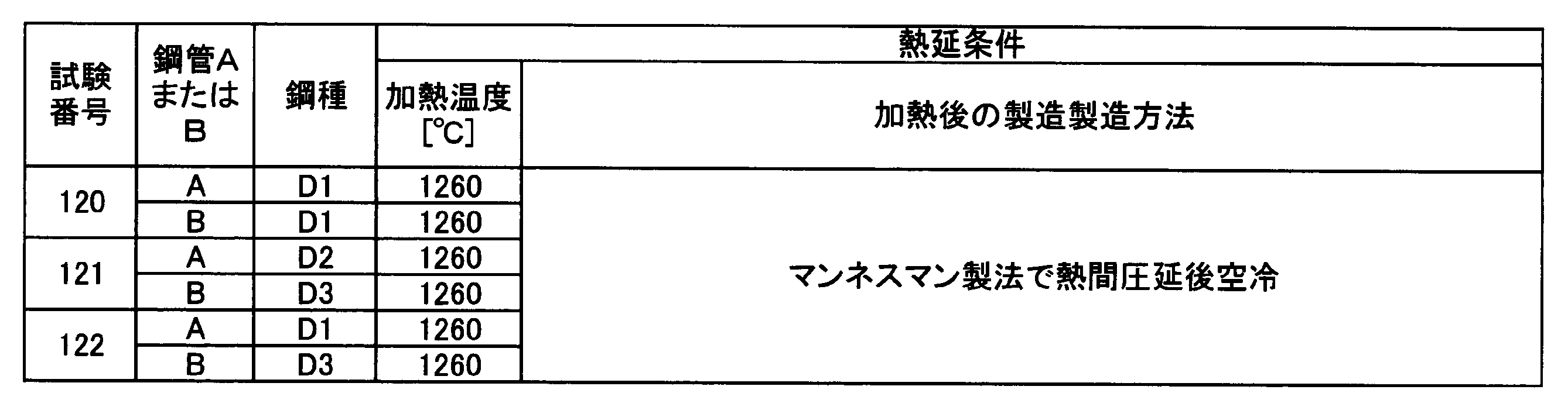
所定の鋼成分を有するブルームを1200℃以上1300℃以下に加熱し、いわゆるマンネスマン製法で鋼管とし、空冷する。その後、900℃以上950℃以下に加熱して水冷する焼入れ処理(Q)及び500℃以上700℃以下に加熱する焼戻し処理(T)を行い、空冷することで、YPE型のシームレス鋼管とすることができる。
また、(i)や(ii)のような方法で製造したラウンド型の鋼管に、熱硬化型樹脂をコーティングすることで、YPE型の鋼管とすることができる。熱硬化型樹脂のコーティングは、例えば、鋼管をリング状のインダクションヒーターなどで200℃~250℃の温度域に加熱し、その温度域でエポキシ樹脂等の熱硬化型樹脂をスプレー等で吹き付けることにより、行うことができる。
また、(i)や(ii)のような方法で製造したラウンド型の鋼管を200℃~250℃程度の温度域に加熱し、この温度域で10分以上保持して歪時効を生じさせることで、YPE型の鋼管とすることができる。これは、C、Nのような侵入型固溶元素が時間の経過とともに鋼材中の転位に固着していくためであると考えられる。
なお、熱加工型樹脂のコーティングと、時効処理とは、鋼管を同じ温度域に加熱する処理であるため、鋼管の機械的特性に及ぼす影響が、ほぼ等価である。
上記(iii)~(v)のような方法を用いれば、引張強度が450MPa以上850MPa以下のYPE型の鋼管を安定して製造できる。
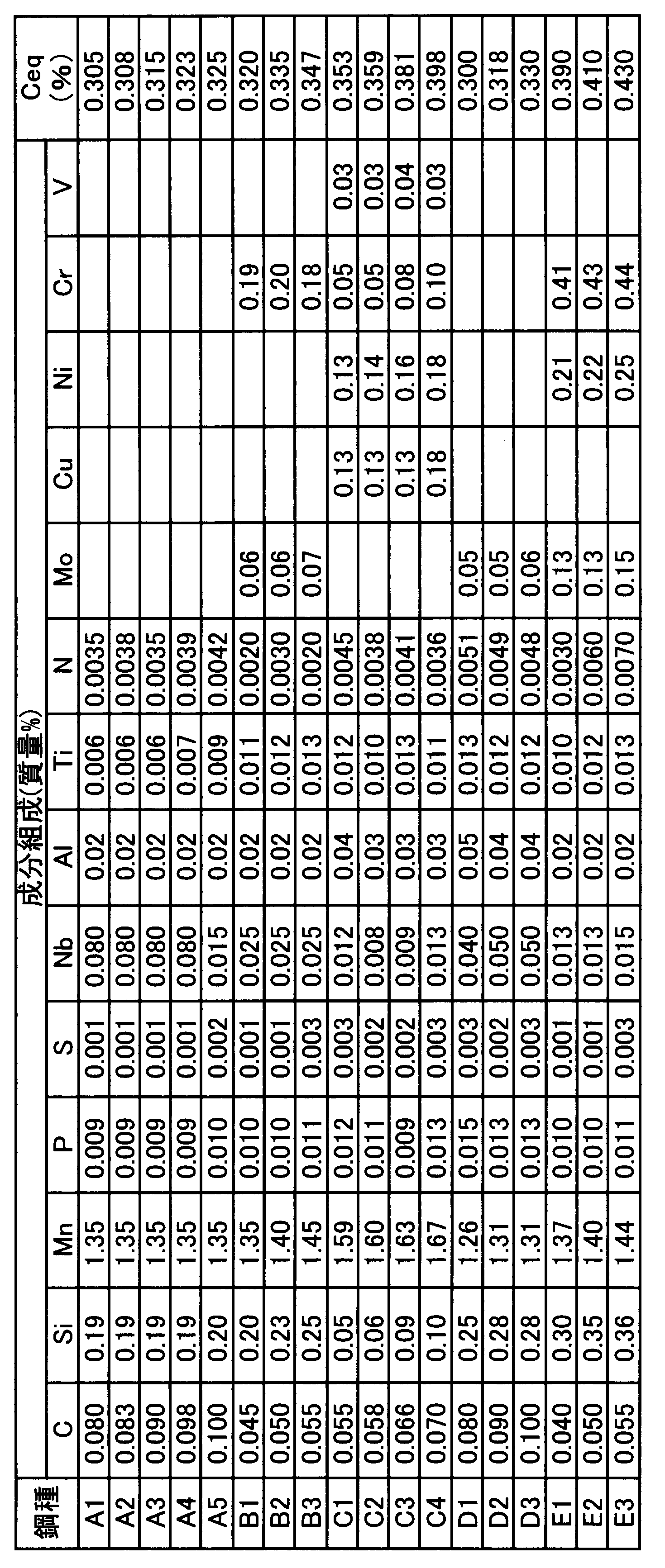
なお、表1の空欄は、測定限界値以下の含有量であったことを示している。表15中の時効処理は、鋼管を200℃に加熱し、その温度域で10分間保持したことを示している。表15中の焼戻しは、鋼管を600℃に加熱したことを示している。表13及び表14中のQTは、930℃に加熱後に水冷する焼入れ処理と、650℃に加熱する焼戻し処理を行ったことを示している。熱硬化型樹脂のコーティングは、鋼管をリング状のインダクションヒーターなどで200℃~250℃の温度域に加熱し、その温度域でエポキシ樹脂をスプレー等で吹き付けることにより行った。鋼板及び鋼管の引張試験は、API Specification 5Lに規定された全厚引張試験方法に準じて行った。

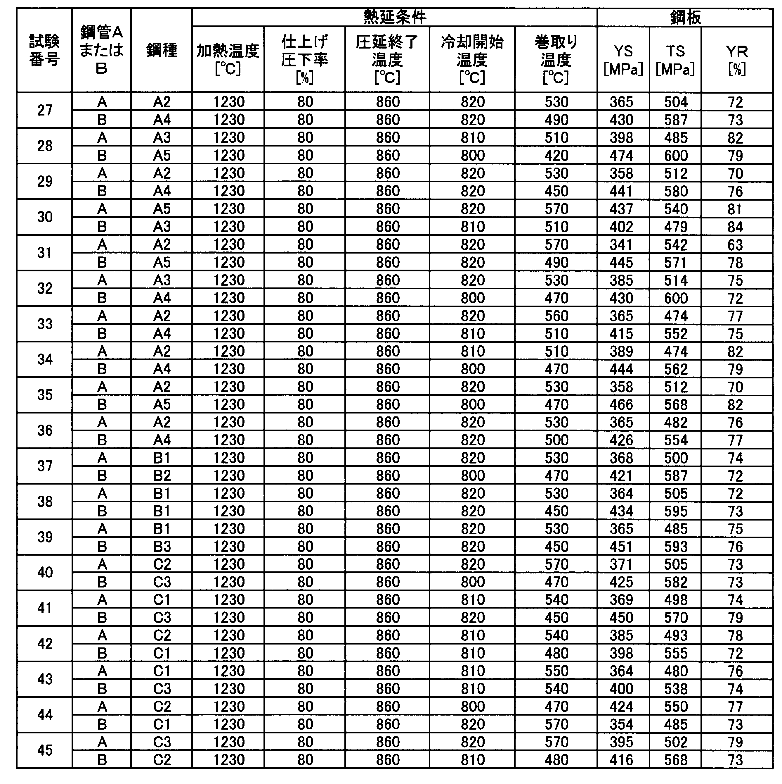
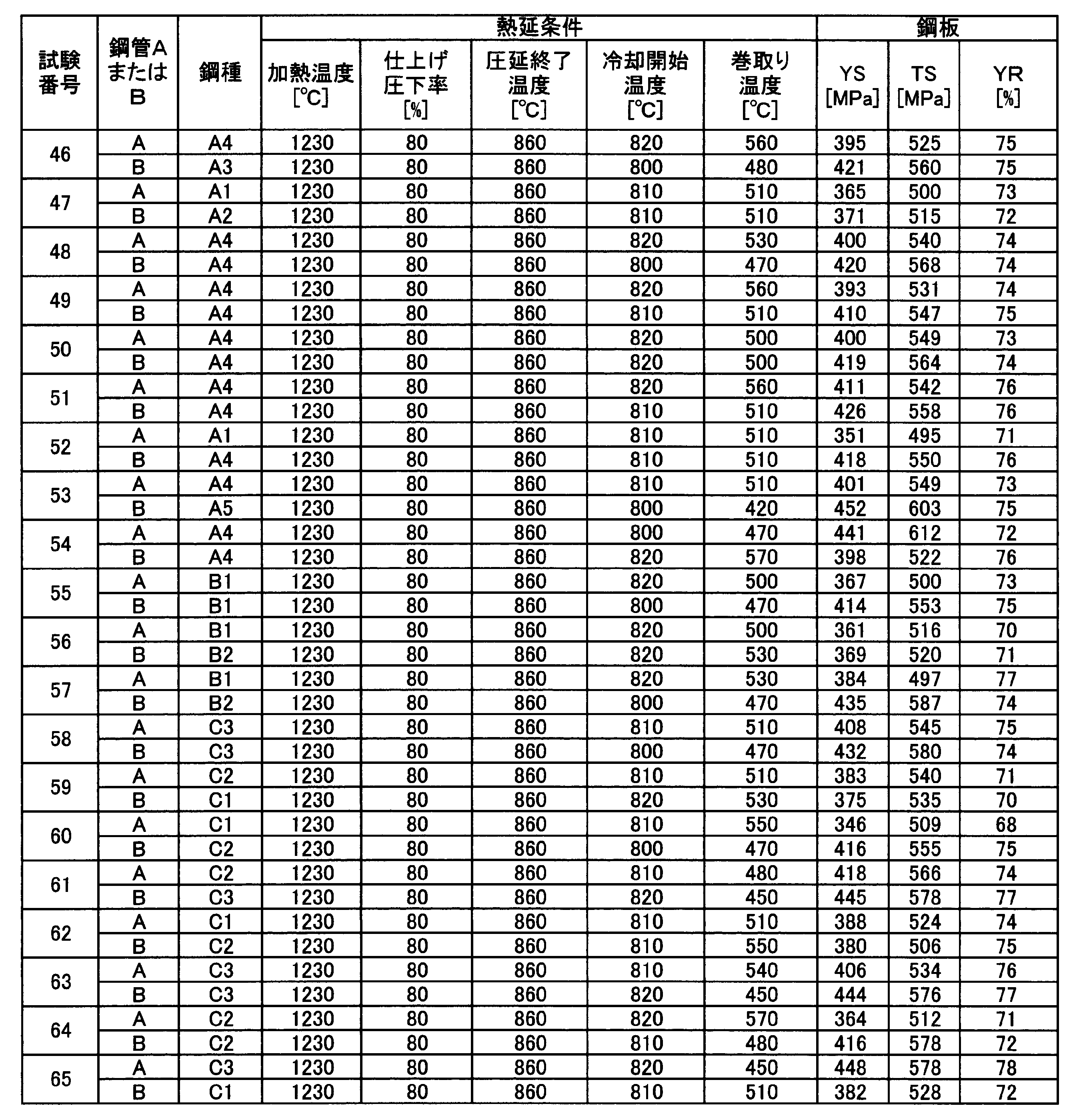
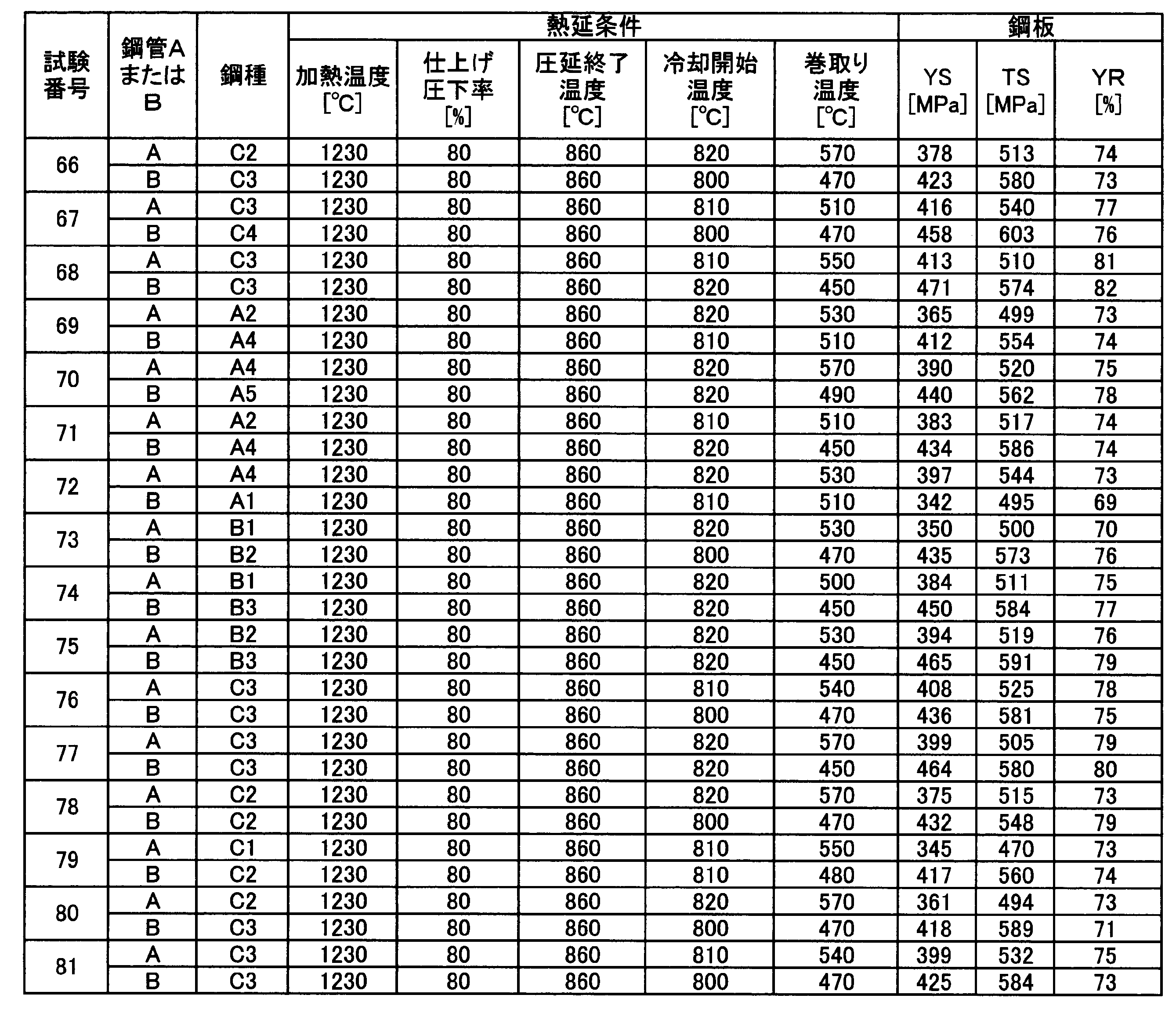
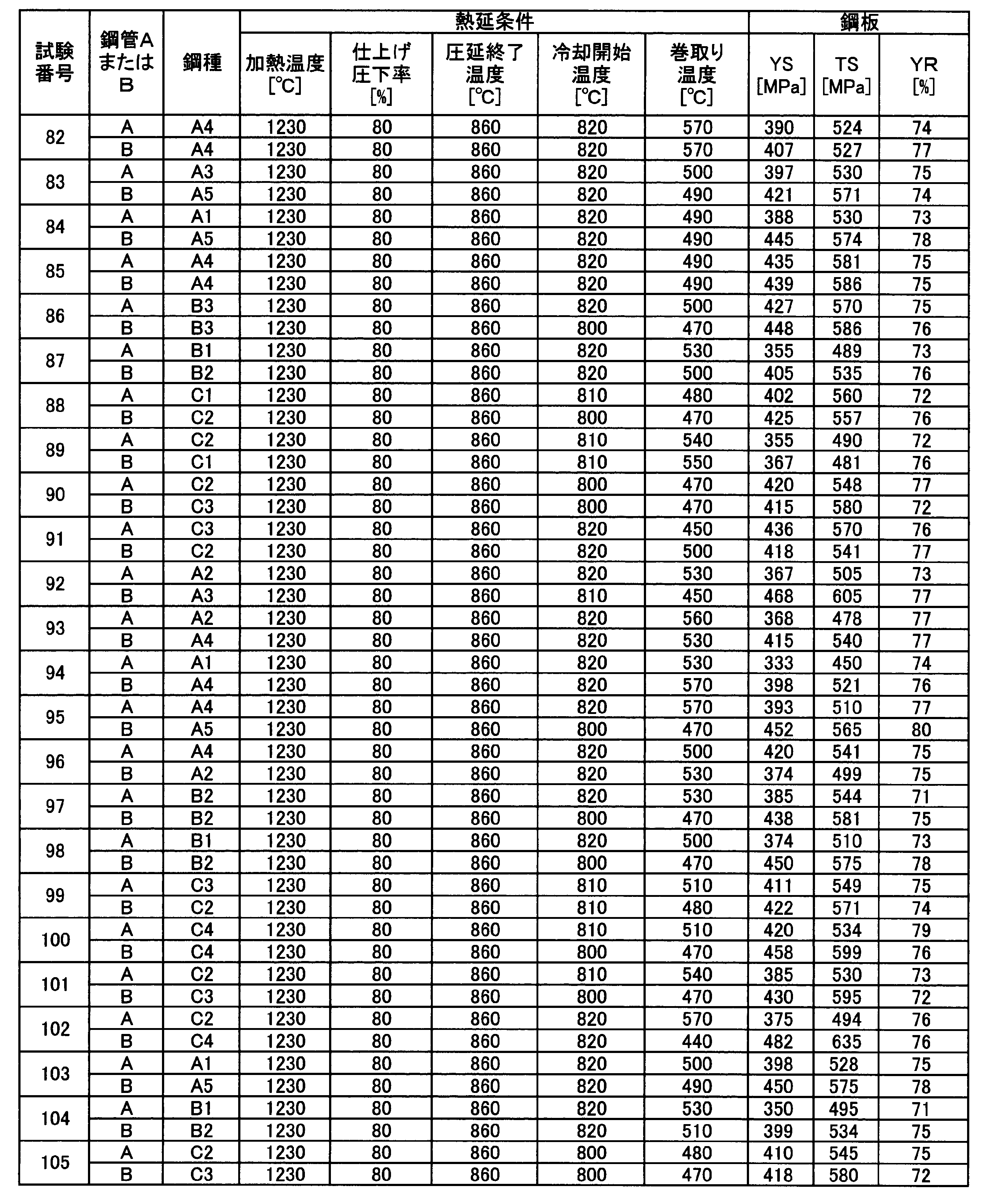






2、A、B 鋼管
3 溶接部
4 ドラム
5 熱影響部(HAZ)
10 試験装置
11 曲げ戻し用ベッド
12 曲げ用ベッド
13 曲げ荷重負荷
Claims (12)
- 複数の鋼管の端部同士が溶接によって接合された複数の溶接部を有するパイプラインであって、
前記複数の鋼管は、1種以上の鋼成分を有する複数チャージの溶鋼から製造され;
前記各鋼管の長手方向に応力を加えた時に得られる応力-歪み曲線に降伏点伸びを有しておらず;
前記各鋼管の管厚である単位mmのtと平均管径である単位mmのDとが、下記式1を満足し;
前記複数の溶接部では、互いに溶接された一方の鋼管の降伏強度と他方の鋼管の降伏強度との差である単位MPaのΔYSと、前記一方の鋼管及び前記他方の鋼管のうち、前記降伏強度が低い方の鋼管の引張強度に対する前記降伏強度の比である降伏比を示すYRとが下記式2を満足する;
ことを特徴とするパイプライン。
t/D×100≦6…(1)
ΔYS≦-1.75×YR+230…(2) - 前記鋼成分が、質量%で、
C:0.04%以上0.15%以下、
Mn:1.0%以上1.75%以下、
Nb:0.005%以上0.10%以下、
Ti:0.005%以上0.02%以下、
Al:0.001%以上0.06%以下
を含有し、
Si:0.4%以下、
P:0.015%以下、
S:0.005%以下、
N:0.007%以下
に制限し、
残部がFe及び不可避的不純物からなり、
前記一方の鋼管と前記他方の鋼管との間の、下記式3で表されるCeq値の差の絶対値であるΔCeq値が、0.045%以下であり、
前記複数の鋼管の前記引張強度が、450MPa以上850MPa以下である
ことを特徴とする、請求項1に記載のパイプライン。
Ceq=[C]+[Mn]/6…(3)
ここで、[C]、[Mn]は、C、Mnの質量%での含有量を示す。 - さらに、前記鋼成分が、質量%で、
Cu:0.1%以上1.0%以下、
Ni:0.1%以上1.0%以下、
Cr:0.1%以上1.0%以下、
Mo:0.05%以上0.3%以下、
V:0.01%以上0.1%以下、
の1種以上を含有し、前記ΔCeq値が式4で表される
ことを特徴とする請求項2に記載のパイプライン。
Ceq=[C]+[Mn]/6+([Ni]+[Cu])/15+([Cr]+[Mo]+[V])/5…(4)
ここで、[C]、[Mn]、[Ni]、[Cu]、[Cr]、[Mo]、[V]は、C、Mn、Ni、Cu、Cr、Mo、Vの質量%での含有量を示す。 - 複数の鋼管の端部同士が溶接によって接合された複数の溶接部を有するパイプラインであって、
前記複数の鋼管は、1種以上の鋼成分を有する複数チャージの溶鋼から製造され;
前記各鋼管の長手方向に応力を加えた時に得られる応力-歪み曲線に降伏点伸びを有し;
前記各鋼管の管厚である単位mmのtと平均管径である単位mmのDとが、下記式5を満足し;
前記複数の溶接部では、互いに溶接された一方の鋼管の降伏強度と他方の鋼管の降伏強度との差である単位MPaのΔYSと、前記一方の鋼管と前記他方の鋼管のうち、前記降伏強度が低い方の鋼管の引張強度に対する前記降伏強度の比である降伏比を示すYRとが下記式6を満足する;
ことを特徴とするパイプライン。
t/D×100≦6…(5)
ΔYS≦-0.69×YR+125…(6) - 前記鋼成分が、質量%で、
C:0.04%以上0.15%以下、
Mn:1.0%以上1.75%以下、
Nb:0.005%以上0.05%以下、
Ti:0.005%以上0.02%以下、
Al:0.001%以上0.06%以下
を含有し、
Si:0.4%以下、
P:0.015%以下、
S:0.005%以下、
N:0.007%以下、
に制限し、
残部がFe及び不可避的不純物からなり、
前記一方の鋼管と前記他方の鋼管との間の、下記式7で表されるCeq値の差の絶対値であるΔCeq値が、0.045%以下であり、
前記複数の鋼管の前記引張強度が、450MPa以上850MPa以下であり、
前記複数の鋼管の表裏面に熱加工型樹脂がコーティングされている
ことを特徴とする、請求項4に記載のパイプライン。
Ceq=[C]+[Mn]/6…(7)
ここで、[C]、[Mn]は、C、Mnの質量%での含有量を示す。 - さらに、前記鋼成分が、質量%で、
Cu:0.1%以上1.0%以下、
Ni:0.1%以上1.0%以下、
Cr:0.1%以上1.0%以下、
Mo:0.05%以上0.3%以下、
V:0.01%以上0.1%以下、
の1種以上を含有し、前記ΔCeq値が式8で表される
ことを特徴とする請求項5に記載のパイプライン。
Ceq=[C]+[Mn]/6+([Ni]+[Cu])/15+([Cr]+[Mo]+[V])/5…(8)
ここで、[C]、[Mn]、[Ni]、[Cu]、[Cr]、[Mo]、[V]は、C、Mn、Ni、Cu、Cr、Mo、Vの質量%での含有量を示す。 - 前記鋼成分が、質量%で、
C:0.04%以上0.15%以下、
Mn:1.0%以上1.75%以下、
Nb:0.005%以上0.05%以下、
Ti:0.005%以上0.02%以下、
Al:0.001%以上0.06%以下
を含有し、
Si:0.4%以下、
P:0.015%以下、
S:0.005%以下、
N:0.007%以下、
に制限し、
残部がFe及び不可避的不純物からなり、
前記一方の鋼管と前記他方の鋼管との間の、下記式9で表されるCeq値の差の絶対値であるΔCeq値が0.045%以下であり、
前記複数の鋼管の前記引張強度が、450MPa以上850MPa以下である、
ことを特徴とする、請求項4に記載のパイプライン。
Ceq=[C]+[Mn]/6…(9)
ここで、[C]、[Mn]は、C、Mnの質量%での含有量を示す。 - さらに、前記鋼成分が、質量%で、
Cu:0.1%以上1.0%以下、
Ni:0.1%以上1.0%以下、
Cr:0.1%以上1.0%以下、
Mo:0.05%以上0.3%以下、
V:0.01%以上0.1%以下、
の1種以上を含有し、前記ΔCeq値が式10で表される
ことを特徴とする請求項7に記載のパイプライン。
Ceq=[C]+[Mn]/6+([Ni]+[Cu])/15+([Cr]+[Mo]+[V])/5…(10)
ここで、[C]、[Mn]、[Ni]、[Cu]、[Cr]、[Mo]、[V]は、C、Mn、Ni、Cu、Cr、Mo、Vの質量%での含有量を示す。 - 請求項1に記載のパイプラインを製造する方法であって、
前記複数の鋼管の前記降伏強度を測定する第1の降伏強度測定工程と;
前記ΔYSが前記式2を満足する鋼管同士を溶接する第1の溶接工程と;
を有することを特徴とするパイプラインの製造方法。 - 請求項1に記載のパイプラインを製造する方法であって、
前記複数の鋼管に、それぞれを特定できる製造番号を圧延が行われた順に付与する第1の番号付与工程と;
同一の溶鋼、同一の熱延コイルから製造されてかつ前記製造番号の差が1以上5以下である鋼管同士を溶接する第2の溶接工程と;
を有することを特徴とするパイプラインの製造方法。 - 請求項4に記載のパイプラインを製造する方法であって、
前記複数の鋼管の前記降伏強度を測定する第2の降伏強度測定工程と;
前記ΔYSが前記式6を満足する鋼管同士を溶接する第3の溶接工程と;
を有することを特徴とするパイプラインの製造方法。 - 請求項4に記載のパイプラインを製造する方法であって、
前記複数の鋼管に、それぞれを特定できる製造番号を圧延が行われた順に付与する第2の番号付与工程と;
同一の溶鋼から製造されてかつ前記製造番号の差が1以上5以下の鋼管同士を溶接する第4の溶接工程と;
を有することを特徴とするパイプラインの製造方法。
Priority Applications (6)
| Application Number | Priority Date | Filing Date | Title |
|---|---|---|---|
| BR112014018236-1A BR112014018236B1 (pt) | 2012-01-27 | 2013-01-28 | Tubulações e métodos de produção da mesmas |
| EP13740715.1A EP2808415B1 (en) | 2012-01-27 | 2013-01-28 | Pipeline and manufacturing method thereof |
| AU2013212844A AU2013212844B2 (en) | 2012-01-27 | 2013-01-28 | Pipeline and manufacturing method thereof |
| US14/371,592 US9737962B2 (en) | 2012-01-27 | 2013-01-28 | Pipeline and manufacturing method thereof |
| ES13740715.1T ES2659172T3 (es) | 2012-01-27 | 2013-01-28 | Ducto y método de fabricar el mismo |
| US15/649,469 US10449636B2 (en) | 2012-01-27 | 2017-07-13 | Pipeline and manufacturing method thereof |
Applications Claiming Priority (2)
| Application Number | Priority Date | Filing Date | Title |
|---|---|---|---|
| JP2012014991 | 2012-01-27 | ||
| JP2012-014991 | 2012-01-27 |
Related Child Applications (2)
| Application Number | Title | Priority Date | Filing Date |
|---|---|---|---|
| US14/371,592 A-371-Of-International US9737962B2 (en) | 2012-01-27 | 2013-01-28 | Pipeline and manufacturing method thereof |
| US15/649,469 Division US10449636B2 (en) | 2012-01-27 | 2017-07-13 | Pipeline and manufacturing method thereof |
Publications (1)
| Publication Number | Publication Date |
|---|---|
| WO2013111902A1 true WO2013111902A1 (ja) | 2013-08-01 |
Family
ID=48873612
Family Applications (1)
| Application Number | Title | Priority Date | Filing Date |
|---|---|---|---|
| PCT/JP2013/051765 Ceased WO2013111902A1 (ja) | 2012-01-27 | 2013-01-28 | パイプライン及びその製造方法 |
Country Status (7)
| Country | Link |
|---|---|
| US (2) | US9737962B2 (ja) |
| EP (1) | EP2808415B1 (ja) |
| JP (1) | JP5618017B2 (ja) |
| AU (1) | AU2013212844B2 (ja) |
| BR (1) | BR112014018236B1 (ja) |
| ES (1) | ES2659172T3 (ja) |
| WO (1) | WO2013111902A1 (ja) |
Cited By (3)
| Publication number | Priority date | Publication date | Assignee | Title |
|---|---|---|---|---|
| JP2023502071A (ja) * | 2019-11-15 | 2023-01-20 | ジェイ. レイ マクダーモット, エス.エー. | ハイブリッド機械式ライニング管の方法および装置 |
| WO2023149364A1 (ja) | 2022-02-07 | 2023-08-10 | 日本製鉄株式会社 | 鋼管、鋼管群、パイプライン、及び鋼管製造方法 |
| KR20240130761A (ko) | 2022-02-07 | 2024-08-29 | 닛폰세이테츠 가부시키가이샤 | 강관, 강관군, 파이프라인, 및 강관 제조 방법 |
Families Citing this family (2)
| Publication number | Priority date | Publication date | Assignee | Title |
|---|---|---|---|---|
| EP2905353B8 (en) * | 2012-10-04 | 2019-08-21 | Nippon Steel Corporation | Shaped steel wire for undersea-cable protecting tube, manufacturing method therefor, and pressure-resistant layer |
| FR3053755B1 (fr) * | 2016-07-06 | 2018-08-17 | Saipem S.A. | Procede de raccordement de deux elements unitaires d'une conduite sous-marine de transport de fluides soumise a la fatigue |
Citations (5)
| Publication number | Priority date | Publication date | Assignee | Title |
|---|---|---|---|---|
| JPH03133576A (ja) | 1989-07-06 | 1991-06-06 | Kawasaki Steel Corp | リールバージ敷設用電縫鋼管ラインパイプの円周溶接方法 |
| JPH03211255A (ja) | 1989-09-08 | 1991-09-17 | Kawasaki Steel Corp | リールバージ敷設性に優れた高靭性電縫鋼管 |
| JP2001192773A (ja) | 2000-01-13 | 2001-07-17 | Sumitomo Metal Ind Ltd | ラインパイプ用鋼 |
| JP2006122932A (ja) * | 2004-10-27 | 2006-05-18 | Jfe Steel Kk | ラインパイプ用低降伏比電縫鋼管の製造方法 |
| JP2006281217A (ja) | 2005-03-31 | 2006-10-19 | Sumitomo Metal Ind Ltd | 連結管及びその製造方法 |
Family Cites Families (7)
| Publication number | Priority date | Publication date | Assignee | Title |
|---|---|---|---|---|
| US5134267A (en) * | 1989-07-06 | 1992-07-28 | Kawasaki Steel Corporation | Method of conducting circumferential welding of electric welded steel line pipe to be laid by reel barge |
| US5491637A (en) * | 1994-03-18 | 1996-02-13 | Amoco Corporation | Method of creating a comprehensive manufacturing, shipping and location history for pipe joints |
| JP5068645B2 (ja) * | 2005-04-04 | 2012-11-07 | 新日本製鐵株式会社 | 延性破壊特性に優れた高強度鋼板及び高強度溶接鋼管並びにそれらの製造方法 |
| MXPA05008339A (es) * | 2005-08-04 | 2007-02-05 | Tenaris Connections Ag | Acero de alta resistencia para tubos de acero soldables y sin costura. |
| NO325936B1 (no) * | 2006-12-11 | 2008-08-18 | Statoil Asa | Fremgangsmate for utlegging av en rorledning med en innvendig korrosjonsbestandig kledning |
| KR101257547B1 (ko) * | 2007-07-23 | 2013-04-23 | 신닛테츠스미킨 카부시키카이샤 | 변형 특성이 우수한 강관 및 그 제조 방법 |
| CA2808119C (en) * | 2011-04-19 | 2014-07-08 | Nippon Steel & Sumitomo Metal Corporation | Electric resistance welded oil country tubular goods and manufacturing method of electric resistance welded oil country tubular goods |
-
2013
- 2013-01-28 EP EP13740715.1A patent/EP2808415B1/en active Active
- 2013-01-28 AU AU2013212844A patent/AU2013212844B2/en not_active Ceased
- 2013-01-28 BR BR112014018236-1A patent/BR112014018236B1/pt not_active IP Right Cessation
- 2013-01-28 US US14/371,592 patent/US9737962B2/en not_active Expired - Fee Related
- 2013-01-28 JP JP2013555341A patent/JP5618017B2/ja active Active
- 2013-01-28 ES ES13740715.1T patent/ES2659172T3/es active Active
- 2013-01-28 WO PCT/JP2013/051765 patent/WO2013111902A1/ja not_active Ceased
-
2017
- 2017-07-13 US US15/649,469 patent/US10449636B2/en not_active Expired - Fee Related
Patent Citations (5)
| Publication number | Priority date | Publication date | Assignee | Title |
|---|---|---|---|---|
| JPH03133576A (ja) | 1989-07-06 | 1991-06-06 | Kawasaki Steel Corp | リールバージ敷設用電縫鋼管ラインパイプの円周溶接方法 |
| JPH03211255A (ja) | 1989-09-08 | 1991-09-17 | Kawasaki Steel Corp | リールバージ敷設性に優れた高靭性電縫鋼管 |
| JP2001192773A (ja) | 2000-01-13 | 2001-07-17 | Sumitomo Metal Ind Ltd | ラインパイプ用鋼 |
| JP2006122932A (ja) * | 2004-10-27 | 2006-05-18 | Jfe Steel Kk | ラインパイプ用低降伏比電縫鋼管の製造方法 |
| JP2006281217A (ja) | 2005-03-31 | 2006-10-19 | Sumitomo Metal Ind Ltd | 連結管及びその製造方法 |
Non-Patent Citations (1)
| Title |
|---|
| See also references of EP2808415A4 |
Cited By (3)
| Publication number | Priority date | Publication date | Assignee | Title |
|---|---|---|---|---|
| JP2023502071A (ja) * | 2019-11-15 | 2023-01-20 | ジェイ. レイ マクダーモット, エス.エー. | ハイブリッド機械式ライニング管の方法および装置 |
| WO2023149364A1 (ja) | 2022-02-07 | 2023-08-10 | 日本製鉄株式会社 | 鋼管、鋼管群、パイプライン、及び鋼管製造方法 |
| KR20240130761A (ko) | 2022-02-07 | 2024-08-29 | 닛폰세이테츠 가부시키가이샤 | 강관, 강관군, 파이프라인, 및 강관 제조 방법 |
Also Published As
| Publication number | Publication date |
|---|---|
| JPWO2013111902A1 (ja) | 2015-05-11 |
| BR112014018236A2 (ja) | 2017-06-20 |
| US10449636B2 (en) | 2019-10-22 |
| AU2013212844B2 (en) | 2015-07-16 |
| AU2013212844A1 (en) | 2014-07-24 |
| EP2808415A1 (en) | 2014-12-03 |
| EP2808415A4 (en) | 2016-01-13 |
| JP5618017B2 (ja) | 2014-11-05 |
| BR112014018236A8 (pt) | 2017-07-11 |
| US20150004426A1 (en) | 2015-01-01 |
| US9737962B2 (en) | 2017-08-22 |
| ES2659172T3 (es) | 2018-03-14 |
| EP2808415B1 (en) | 2017-11-22 |
| BR112014018236B1 (pt) | 2019-04-02 |
| US20170304953A1 (en) | 2017-10-26 |
Similar Documents
| Publication | Publication Date | Title |
|---|---|---|
| CN104011245B (zh) | 高张力热轧钢板及其制造方法 | |
| JP6816827B2 (ja) | 角鋼管の製造方法および角鋼管 | |
| US10449636B2 (en) | Pipeline and manufacturing method thereof | |
| WO2011065578A1 (ja) | 高い圧縮強度および高い靭性に優れたラインパイプ用溶接鋼管及びその製造方法 | |
| CN102549186B (zh) | 高强度钢管、高强度钢管用钢板及它们的制造方法 | |
| WO2015151469A1 (ja) | 耐歪時効特性及び耐hic特性に優れた高変形能ラインパイプ用鋼材およびその製造方法ならびに溶接鋼管 | |
| JP6070642B2 (ja) | 高強度でかつ低温靭性に優れた熱延鋼板およびその製造方法 | |
| CN105452506A (zh) | 焊接区质量优异的电焊钢管及其制造方法 | |
| US20180320257A9 (en) | Thick steel plate for structural pipes or tubes, method of producing thick steel plate for structural pipes or tubes, and structural pipes and tubes | |
| JP6048615B2 (ja) | 耐歪時効特性及び耐hic特性に優れた高変形能ラインパイプ用鋼材およびその製造方法ならびに溶接鋼管 | |
| JP2019116659A (ja) | 疲労強度に優れた厚肉大径電縫鋼管およびその製造方法 | |
| JP2019116658A (ja) | 疲労強度に優れた電縫鋼管およびその製造方法 | |
| JP5786351B2 (ja) | 耐コラプス性能の優れたラインパイプ用鋼管 | |
| JP2009228099A (ja) | ラインパイプ用uoe鋼管及びその製造方法 | |
| CN105102654A (zh) | 厚壁钢管用钢板、其制造方法以及厚壁高强度钢管 | |
| JP4442541B2 (ja) | ラインパイプ向け低yr電縫鋼管の製造方法 | |
| JP6984785B2 (ja) | 角形鋼管およびその製造方法並びに建築構造物 | |
| JP2006289482A (ja) | ラインパイプ用低降伏比電縫鋼管の製造方法 | |
| JP6658385B2 (ja) | 鋼管の製造方法 | |
| JP5353760B2 (ja) | 変形特性に優れる電縫鋼管およびその製造方法 | |
| JP5782830B2 (ja) | 高圧縮強度鋼管及びその製造方法 | |
| JP2007015008A (ja) | ラインパイプ向け低yr電縫鋼管の製造方法 | |
| JP2020110840A (ja) | 電縫鋼管およびその製造方法 | |
| JP7700876B2 (ja) | 熱延鋼板、電縫鋼管および角形鋼管ならびにラインパイプおよび建築構造物 | |
| JP5782829B2 (ja) | 高圧縮強度鋼管及びその製造方法 |
Legal Events
| Date | Code | Title | Description |
|---|---|---|---|
| 121 | Ep: the epo has been informed by wipo that ep was designated in this application |
Ref document number: 13740715 Country of ref document: EP Kind code of ref document: A1 |
|
| ENP | Entry into the national phase |
Ref document number: 2013555341 Country of ref document: JP Kind code of ref document: A |
|
| REEP | Request for entry into the european phase |
Ref document number: 2013740715 Country of ref document: EP |
|
| WWE | Wipo information: entry into national phase |
Ref document number: 2013740715 Country of ref document: EP |
|
| WWE | Wipo information: entry into national phase |
Ref document number: 14371592 Country of ref document: US |
|
| ENP | Entry into the national phase |
Ref document number: 2013212844 Country of ref document: AU Date of ref document: 20130128 Kind code of ref document: A |
|
| NENP | Non-entry into the national phase |
Ref country code: DE |
|
| REG | Reference to national code |
Ref country code: BR Ref legal event code: B01A Ref document number: 112014018236 Country of ref document: BR |
|
| ENP | Entry into the national phase |
Ref document number: 112014018236 Country of ref document: BR Kind code of ref document: A2 Effective date: 20140724 |