WO2013114537A1 - Dispositif de recirculation des gaz de soufflage de carter pour moteur à combustion interne - Google Patents
Dispositif de recirculation des gaz de soufflage de carter pour moteur à combustion interne Download PDFInfo
- Publication number
- WO2013114537A1 WO2013114537A1 PCT/JP2012/052002 JP2012052002W WO2013114537A1 WO 2013114537 A1 WO2013114537 A1 WO 2013114537A1 JP 2012052002 W JP2012052002 W JP 2012052002W WO 2013114537 A1 WO2013114537 A1 WO 2013114537A1
- Authority
- WO
- WIPO (PCT)
- Prior art keywords
- pipe
- gas
- blow
- internal combustion
- combustion engine
- Prior art date
- Legal status (The legal status is an assumption and is not a legal conclusion. Google has not performed a legal analysis and makes no representation as to the accuracy of the status listed.)
- Ceased
Links
Images


Classifications
-
- F—MECHANICAL ENGINEERING; LIGHTING; HEATING; WEAPONS; BLASTING
- F01—MACHINES OR ENGINES IN GENERAL; ENGINE PLANTS IN GENERAL; STEAM ENGINES
- F01M—LUBRICATING OF MACHINES OR ENGINES IN GENERAL; LUBRICATING INTERNAL COMBUSTION ENGINES; CRANKCASE VENTILATING
- F01M13/00—Crankcase ventilating or breathing
-
- F—MECHANICAL ENGINEERING; LIGHTING; HEATING; WEAPONS; BLASTING
- F01—MACHINES OR ENGINES IN GENERAL; ENGINE PLANTS IN GENERAL; STEAM ENGINES
- F01M—LUBRICATING OF MACHINES OR ENGINES IN GENERAL; LUBRICATING INTERNAL COMBUSTION ENGINES; CRANKCASE VENTILATING
- F01M11/00—Component parts, details or accessories, not provided for in, or of interest apart from, groups F01M1/00 - F01M9/00
- F01M11/10—Indicating devices; Other safety devices
-
- F—MECHANICAL ENGINEERING; LIGHTING; HEATING; WEAPONS; BLASTING
- F01—MACHINES OR ENGINES IN GENERAL; ENGINE PLANTS IN GENERAL; STEAM ENGINES
- F01M—LUBRICATING OF MACHINES OR ENGINES IN GENERAL; LUBRICATING INTERNAL COMBUSTION ENGINES; CRANKCASE VENTILATING
- F01M13/00—Crankcase ventilating or breathing
- F01M13/02—Crankcase ventilating or breathing by means of additional source of positive or negative pressure
- F01M13/021—Crankcase ventilating or breathing by means of additional source of positive or negative pressure of negative pressure
- F01M13/022—Crankcase ventilating or breathing by means of additional source of positive or negative pressure of negative pressure using engine inlet suction
- F01M13/023—Control valves in suction conduit
-
- F—MECHANICAL ENGINEERING; LIGHTING; HEATING; WEAPONS; BLASTING
- F02—COMBUSTION ENGINES; HOT-GAS OR COMBUSTION-PRODUCT ENGINE PLANTS
- F02D—CONTROLLING COMBUSTION ENGINES
- F02D41/00—Electrical control of supply of combustible mixture or its constituents
- F02D41/0002—Controlling intake air
- F02D41/0007—Controlling intake air for control of turbo-charged or super-charged engines
-
- F—MECHANICAL ENGINEERING; LIGHTING; HEATING; WEAPONS; BLASTING
- F02—COMBUSTION ENGINES; HOT-GAS OR COMBUSTION-PRODUCT ENGINE PLANTS
- F02D—CONTROLLING COMBUSTION ENGINES
- F02D41/00—Electrical control of supply of combustible mixture or its constituents
- F02D41/22—Safety or indicating devices for abnormal conditions
-
- F—MECHANICAL ENGINEERING; LIGHTING; HEATING; WEAPONS; BLASTING
- F02—COMBUSTION ENGINES; HOT-GAS OR COMBUSTION-PRODUCT ENGINE PLANTS
- F02M—SUPPLYING COMBUSTION ENGINES IN GENERAL WITH COMBUSTIBLE MIXTURES OR CONSTITUENTS THEREOF
- F02M25/00—Engine-pertinent apparatus for adding non-fuel substances or small quantities of secondary fuel to combustion-air, main fuel or fuel-air mixture
- F02M25/06—Engine-pertinent apparatus for adding non-fuel substances or small quantities of secondary fuel to combustion-air, main fuel or fuel-air mixture adding lubricant vapours
-
- F—MECHANICAL ENGINEERING; LIGHTING; HEATING; WEAPONS; BLASTING
- F01—MACHINES OR ENGINES IN GENERAL; ENGINE PLANTS IN GENERAL; STEAM ENGINES
- F01M—LUBRICATING OF MACHINES OR ENGINES IN GENERAL; LUBRICATING INTERNAL COMBUSTION ENGINES; CRANKCASE VENTILATING
- F01M13/00—Crankcase ventilating or breathing
- F01M13/02—Crankcase ventilating or breathing by means of additional source of positive or negative pressure
- F01M13/021—Crankcase ventilating or breathing by means of additional source of positive or negative pressure of negative pressure
- F01M2013/027—Crankcase ventilating or breathing by means of additional source of positive or negative pressure of negative pressure with a turbo charger or compressor
-
- F—MECHANICAL ENGINEERING; LIGHTING; HEATING; WEAPONS; BLASTING
- F02—COMBUSTION ENGINES; HOT-GAS OR COMBUSTION-PRODUCT ENGINE PLANTS
- F02D—CONTROLLING COMBUSTION ENGINES
- F02D2250/00—Engine control related to specific problems or objectives
- F02D2250/08—Engine blow-by from crankcase chamber
-
- Y—GENERAL TAGGING OF NEW TECHNOLOGICAL DEVELOPMENTS; GENERAL TAGGING OF CROSS-SECTIONAL TECHNOLOGIES SPANNING OVER SEVERAL SECTIONS OF THE IPC; TECHNICAL SUBJECTS COVERED BY FORMER USPC CROSS-REFERENCE ART COLLECTIONS [XRACs] AND DIGESTS
- Y02—TECHNOLOGIES OR APPLICATIONS FOR MITIGATION OR ADAPTATION AGAINST CLIMATE CHANGE
- Y02T—CLIMATE CHANGE MITIGATION TECHNOLOGIES RELATED TO TRANSPORTATION
- Y02T10/00—Road transport of goods or passengers
- Y02T10/10—Internal combustion engine [ICE] based vehicles
- Y02T10/12—Improving ICE efficiencies
Definitions
- the present invention relates to a blow-by gas recirculation device for an internal combustion engine.
- blow-by gas recirculation device for treating a blow-by gas flowing out from a combustion chamber of an internal combustion engine with a supercharger by returning it to the intake passage of the engine, for example, the one shown in Patent Document 1 is known.
- an ejector is provided in a bypass pipe connecting the upstream portion and the downstream portion of the supercharger in the intake passage of the internal combustion engine, and blow-by gas flowing out from the combustion chamber of the engine flows in.
- a gas pipe is connected to the ejector.
- blow-by gas reduction device when disconnection (disconnection) of a connection portion with respect to other parts in at least one of the bypass pipe and the gas pipe occurs, blow-by gas is released to the atmosphere from the part where the disconnection occurs. .
- the above-mentioned bypass pipe is connected to the upstream side of the supercharger in the intake passage, so that the blow-by gas is released to the atmosphere.
- the inflow of air from the portion where the detachment has occurred to the upstream of the supercharger in the intake passage also occurs.
- the upstream of the supercharger in the intake passage is almost atmospheric pressure, and even if the inflow of air from the portion where the above-mentioned detachment has occurred to the upstream of the supercharger in the intake passage, the influence is caused by the internal combustion engine. It is hard to appear in driving. Therefore, it is not possible to detect the disconnection by monitoring the change in the engine operating state due to the disconnection of the connection portion with respect to the other parts in at least one of the bypass pipe and the gas pipe.
- a detector that includes a signal line that is disconnected when a connection portion with respect to another component in at least one of the bypass pipe and the gas pipe is disconnected, and detects the disconnection of the bypass pipe based on the disconnection of the signal. In this case, there is a problem that it takes time to install the detector and the cost for the detector is excessive.
- the pressure in the downstream portion of the supercharger in the intake passage is controlled through the operation of the supercharger provided in the intake passage of the internal combustion engine.
- the pressure is higher than the upstream portion, air flows from the downstream side to the upstream side of the supercharger in the bypass pipe based on the pressure difference.
- an ejector provided in the bypass pipe causes a gas pipe connected to the ejector, that is, a gas pipe into which blow-by gas flowing out from the combustion chamber of the internal combustion engine flows in. Blow-by gas is aspirated.
- the apparatus is configured such that the disconnection of the connection portion with respect to the other components in at least one of the bypass pipe and the gas pipe occurs simultaneously with the disconnection of the other piping located around the internal combustion engine. And as said other piping, what has the influence on the engine operating state which can be monitored by the disconnection is used.
- connection part with respect to the other components in at least one of the bypass pipe and the gas pipe is disconnected, the disconnection of the other pipe also occurs at the same time, so that a change in the engine operation state accompanying the disconnection of the pipe occurs. . Since the change in the engine operating state can be monitored, the disconnection of the other piping based on the change in the engine operating state, in other words, the disconnection of the connection part with respect to other parts in at least one of the bypass pipe and the gas pipe is prevented. Can be detected. In addition, it is not necessary to provide a new detector or the like in order to detect the disconnection of the connection part with respect to other parts in at least one of the bypass pipe and the gas pipe.
- a block valve that operates to allow or block the flow of blow-by gas flowing out from the combustion chamber of the internal combustion engine toward the gas pipe.
- At least one of the bypass pipe and the gas pipe and the other pipe are used as a structure in which the disconnection of the connection portion with respect to other parts in at least one of the bypass pipe and the gas pipe occurs simultaneously with the disconnection of other pipes located around the internal combustion engine.
- a structure in which at least one of the bypass pipe and the gas pipe and another pipe are integrally formed, or a structure in which the pipe is connected by welding or a binding tool. can give.
- a negative pressure pipe for applying the intake negative pressure to an actuator driven by the intake negative pressure of the engine to adjust the supercharging pressure of the internal combustion engine by the supercharger can be used. It is. In this case, disconnection of the other pipe (negative pressure pipe) occurs simultaneously with disconnection of the connection part to at least one of the bypass pipe and the gas pipe, and as a result, intake negative pressure for driving the actuator is reduced. The actuator cannot be properly operated.
- a change in the supercharging pressure of the internal combustion engine occurs as a change in the engine operating state accompanying the disconnection of the negative pressure pipe, and the negative pressure pipe comes off based on the change in the supercharging pressure, in other words, the bypass pipe and the gas pipe It is possible to detect the disconnection of the connection portion with respect to the other components in at least one of the parts.
- the supercharging pressure of the internal combustion engine can be detected by a pressure sensor for detecting the supercharging pressure provided in the internal combustion engine with a supercharger, so that the other in at least one of the bypass pipe and the gas pipe It is not necessary to provide a new detector or the like in order to detect the disconnection of the connection portion with respect to the parts.
- the gas pipe is a first gas pipe.
- a second gas pipe is used in which blow-by gas that has flowed out of the combustion chamber of the internal combustion engine flows into the downstream portion of the throttle valve in the intake passage.
- disconnection of the other pipe (second gas pipe) occurs simultaneously with disconnection of a connection portion with respect to other components in at least one of the bypass pipe and the gas pipe.
- a change in the air-fuel ratio of the internal combustion engine to the lean side occurs as a change in the engine operating state due to the disconnection of the second gas pipe, and the second gas pipe is disconnected based on the change in the air-fuel ratio, in other words, It becomes possible to detect the disconnection of the connecting portion with respect to other parts in at least one of the bypass pipe and the gas pipe.
- the change in the air-fuel ratio of the internal combustion engine is detected based on a signal from a sensor that outputs a signal corresponding to the oxygen concentration in the exhaust, such as an air-fuel ratio sensor or an oxygen sensor provided in the exhaust passage of the engine. Therefore, it is not necessary to provide a new detector or the like in order to detect the disconnection of the connection part with respect to other parts in at least one of the bypass pipe and the gas pipe.
- the bypass pipe is disconnected from the intake passage.
- the bypass pipe is separated from the intake passage at the same time as the other pipes.
- the structure in which the detachment of the bypass pipe from the intake passage occurs simultaneously with the detachment of the other pipe includes a structure in which the bypass pipe and the other pipe are mechanically connected, more specifically, the bypass pipe and the other pipe. And a structure in which the pipe is integrally formed and a structure connected by welding or a binding tool.
- FIG. 1 is a schematic diagram showing an entire internal combustion engine to which a blow-by gas recirculation device of the present invention is applied.
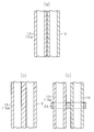
- (A)-(c) is sectional drawing which shows the example of the structure where the detachment
- the flowchart which shows the procedure which detects the disconnection from the intake passage and ejector of the upstream part of a bypass pipe, and copes with those disconnections.
- the fuel injected from the fuel injection valve 2 is sucked into the combustion chamber 4 together with air through the intake passage 3.
- the amount of air taken into the combustion chamber 4 is adjusted by adjusting the opening degree of the throttle valve 5 provided in the intake passage 3.
- the amount of fuel injected from the fuel injection valve 2 is an amount corresponding to the amount of air taken into the combustion chamber 4 through the intake passage 3.
- the mixture composed of them is ignited by the spark plug 6, and when the mixture is burned, the piston 7 reciprocates by the combustion energy at that time.
- the crankshaft 8 that is the output shaft of the internal combustion engine 1 rotates by rotating. Further, the air-fuel mixture after combustion in the combustion chamber 4 is sent to the exhaust passage 9 as exhaust.
- a turbocharger 10 serving as a supercharger is provided in a portion of the exhaust passage 9 and the intake passage 3 upstream of the throttle valve 5.
- the turbocharger 10 includes a turbine wheel 11 that rotates based on the flow of exhaust gas passing through the exhaust passage 9, and a compressor wheel 12 that rotates integrally with the turbine wheel 11 and sends air in the intake passage 3 downstream. ing. Therefore, when the compressor wheel 12 of the turbocharger 10 rotates, the intake pressure (supercharging pressure) of the internal combustion engine 1 increases.
- a bypass passage 13 is connected to the exhaust passage 9 so as to bypass the turbocharger 10 (turbine wheel 11), and a waste gate valve 14 that opens and closes to provide a variable exhaust flow area is provided in the passage 13. It has been. As the exhaust flow area of the bypass passage 13 is reduced through the opening / closing operation of the waste gate valve 14, the flow rate of the exhaust gas passing through the turbine wheel 11 increases and the rotational speed of the turbocharger 10 increases. The supercharging pressure of 1 increases. The waste gate valve 14 is urged toward the fully opened position by the elastic force of the spring, and is displaced in the valve opening direction against the elastic force of the spring by the negative pressure actuator 15.
- the waste gate valve 14 is opened and closed so that the exhaust flow area of the bypass passage 13 is variable. Therefore, the supercharging pressure of the internal combustion engine 1 that is variable based on the operation of the turbocharger 10 is adjusted. Is done.
- the actuator 15 is connected to a negative pressure pipe 16 connected to the downstream portion of the throttle valve 5 in the intake passage 3.
- the negative pressure intake negative pressure
- the waste gate valve 14 is displaced to the valve closing side.
- the negative pressure pipe 16 is provided with a control valve 17 that opens and closes to make the negative pressure pipe 16 communicated or shut off.
- the internal combustion engine 1 is provided with a blow-by gas recirculation device that recirculates the blow-by gas flowing out from the combustion chamber 4 to the crankcase 18 into the intake passage 3 of the engine 1 for processing.
- the apparatus includes a bypass pipe 19 connecting an upstream portion and a downstream portion of the compressor wheel 12 (turbocharger 10) in the intake passage 3, an ejector 20 provided in the bypass pipe 19, and the ejector 20 and the crank.
- a first gas pipe 21 that connects the case 18 is provided.
- the apparatus further includes a block valve 28 that operates to allow or block the flow of blow-by gas flowing out from the combustion chamber 4 to the crankcase 18 toward the first gas pipe 21.
- the block valve 28 is provided between the crankcase 18 and the first gas pipe 21, and allows the flow of blow-by gas in the crankcase 18 toward the first gas pipe 21 by opening the valve, By closing the valve, the flow of blow-by gas in the crankcase 18 toward the first gas pipe 21 is prohibited.
- blow-by gas recirculation device when the blocking valve 28 is open, blow-by gas that has flowed out of the combustion chamber 4 of the internal combustion engine 1 into the crankcase 18 flows into the first gas pipe 21.
- the ejector 20 sucks blow-by gas in the first gas pipe 21 connected to the ejector 20 based on the air flow in the bypass pipe 19. Therefore, when the pressure in the downstream portion of the compressor wheel 12 in the intake passage 3 becomes higher than the pressure in the upstream portion through the operation of the turbocharger 10, the downstream of the compressor wheel 12 in the bypass pipe 19 is based on the pressure difference. Air flows from the side toward the upstream side.
- the blow-by gas recirculation device is also provided with a second gas pipe 22 that connects the crankcase 18 and a portion of the intake passage 3 downstream of the throttle valve 5.
- the second gas pipe 22 is provided with a PCV valve 23 that opens and closes to make the second gas pipe 22 communicated or shut off.
- the blow-by gas flows into the second gas pipe 22 based on the intake negative pressure generated in the downstream portion of the throttle valve 5 in the intake passage 3 and then passes through the second gas pipe 22.
- the air is passed through a portion of the intake passage 3 downstream of the throttle valve 5.
- blow-by gas flowing out from the combustion chamber 4 of the internal combustion engine 1 to the crankcase 18 is returned to the intake passage 3 by the blow-by gas recirculation device and processed.
- Examples of disconnection (disconnection) of the connection parts with respect to other parts in at least one of the bypass pipe 19 and the first gas pipe 21 include the following (A) to (F).
- a portion of the bypass pipe 19 between the ejector 20 and the downstream portion of the compressor wheel 12 in the intake passage 3 (hereinafter referred to as the upstream portion 19a) is disengaged from the downstream portion of the compressor wheel 12 in the intake passage 3.
- a portion of the bypass pipe 19 between the ejector 20 and the upstream portion of the compressor wheel 12 in the intake passage 3 (hereinafter referred to as the downstream portion 19b) is disengaged from the upstream portion of the compressor wheel 12 in the intake passage 3.
- blow-by gas is released from the portion where the disconnection occurs to the atmosphere.
- the inflow of the air from the portion where the detachment has occurred to the upstream of the compressor wheel 12 in the intake passage 3 also occurs.
- the upstream side of the compressor wheel 12 in the intake passage 3 is almost atmospheric pressure, and at least one of the bypass pipe 19 and the first gas pipe 21 in the intake passage 3 from the portion where the connection portion with respect to other parts is disconnected.
- the influence of the inflow hardly appears in the operation of the internal combustion engine 1. Therefore, it is not possible to detect the disconnection by monitoring the change in the engine operating state accompanying the disconnection of the connection portion with respect to the other components in at least one of the bypass pipe 19 and the first gas pipe 21.
- the blow-by gas recirculation device is provided with other piping in which the disconnection of the connection portion with respect to other components in at least one of the bypass pipe 19 and the first gas pipe 21 is located in the vicinity of the internal combustion engine 1. It has a structure that occurs at the same time. And as said other piping, the thing from which the disconnection of the piping has influence on the engine operating state which can be monitored is used. Incidentally, in this embodiment, it is assumed that the situation of (A) and (B) above occurs as the disconnection of the connecting portion with respect to other parts in at least one of the bypass pipe 19 and the first gas pipe 21. Moreover, the negative pressure pipe 16 is used as said other piping.
- the upstream portion 19a in the bypass pipe 19 is disengaged from the ejector 20 and the upstream portion 19a is disengaged from the downstream portion of the compressor wheel 12 in the intake passage 3 from the intake passage 3. It has a structure that occurs simultaneously with the detachment of the negative pressure tube 16. More specifically, when the upstream portion 19a of the bypass pipe 19 is disengaged from the ejector 20, or when the upstream portion 19a is disengaged from the downstream portion of the compressor wheel 12 in the intake passage 3, the negative pressure tube 16 is disengaged from the intake passage 3.
- the upstream portion 19a and the negative pressure pipe 16 are mechanically connected so as to occur simultaneously.
- the upstream part 19a and the negative pressure pipe 16 of the bypass pipe 19 are each formed by a metal pipe, and the upstream part 19a and the negative pressure pipe 16 are in the same direction as shown in FIG. It is connected by welding in the extended state.
- the upstream portion 19a and the negative pressure tube 16 are each a hose made of a flexible material, and may be integrally formed as shown in FIG. 2 (b).
- the upstream portion 19a and the negative pressure tube 16 are formed separately, and the upstream portion 19a and the negative pressure tube 16 are connected by the binding tool 24 in a state where they extend in the same direction. It can be considered to be. 2B and 2C, the upstream portion 19a in the bypass pipe 19 is disengaged from the ejector 20, and the upstream portion 19a is disengaged from the downstream portion of the compressor wheel 12 in the intake passage 3.
- the blow-by gas recirculation device includes an electronic control device 25 as a control unit that executes various operation controls of the internal combustion engine 1.
- the electronic control unit 25 includes a CPU that executes various arithmetic processes related to the above control, a ROM that stores programs and data necessary for the control, a RAM that temporarily stores CPU calculation results, and the like. Input / output ports for inputting / outputting signals are provided.
- the various sensors shown below are connected to the input port of the electronic control unit 25.
- Accelerator position sensor 27 that detects the amount of depression (accelerator operation amount) of the accelerator pedal 26 that is depressed by the driver of the car.
- a throttle position sensor 29 that detects the opening of the throttle valve 5 (throttle opening).
- a pressure sensor 30 that detects the pressure in the downstream side of the throttle valve 5 in the intake passage 3.
- An air-fuel ratio sensor 32 that outputs a signal corresponding to the oxygen concentration in the exhaust gas passing through the exhaust passage 9.
- the output port of the electronic control unit 25 is connected to the drive circuit for the fuel injection valve 2, the drive circuit for the throttle valve 5, the drive circuit for the control valve 17, the drive circuit for the PCV valve 23, the block valve 28, and the like.
- the electronic control unit 25 determines the engine operating state such as the engine speed and the engine load (the amount of air taken into the combustion chamber 4 per cycle of the internal combustion engine 1) based on the detection signals input from the various sensors. To grasp. The engine speed is obtained based on a detection signal from the crank position sensor 31. Further, the engine load is calculated from the intake air amount of the internal combustion engine 1 and the engine rotation speed obtained based on detection signals from the accelerator position sensor 27, the throttle position sensor 29, the pressure sensor 30, and the like. The electronic control unit 25 sends command signals to the drive circuits of various devices such as the fuel injection valve 2, the throttle valve 5, the control valve 17, the PCV valve 23, and the blocking valve 28 based on the engine operating state grasped as described above. Output. Thus, throttle opening control and fuel injection control of the internal combustion engine 1, and opening / closing control of the control valve 17, the PCV valve 23, and the blocking valve 28 are performed through the electronic control device 25.
- the engine operating state such as the engine speed and the engine load (the amount of air taken into the combustion chamber 4 per cycle of
- the fuel injection amount control performed as one of the fuel injection control of the internal combustion engine 1 is realized by injecting the fuel from the fuel injection valve 2 in an amount corresponding to the injection amount command value Qfin obtained based on the engine operating state. Is done.
- the injection amount command value QfinQ is a detection signal from the air-fuel ratio sensor 32 so that the detection signal from the air-fuel ratio sensor 32 becomes a value when the air-fuel mixture in the combustion chamber 4 is burned at the stoichiometric air-fuel ratio. The increase / decrease is corrected based on.
- the injection amount command value Qfin is corrected to decrease.
- the amount of fuel supplied to the combustion chamber 4 is reduced, and the air-fuel ratio of the air-fuel mixture in the combustion chamber 4 is brought close to the stoichiometric air-fuel ratio.
- the detection signal from the air-fuel ratio sensor 32 is a value on the lean side of the value when the air-fuel mixture in the combustion chamber 4 is burned at the stoichiometric air-fuel ratio
- the injection amount command value Qfin is corrected to increase.
- the amount of fuel supplied to the combustion chamber 4 is increased, and the air-fuel ratio of the air-fuel mixture in the combustion chamber 4 is brought close to the stoichiometric air-fuel ratio.
- the negative pressure pipe 16 is located in the vicinity of the upstream portion 19a of the bypass pipe 19 as shown in FIG. Then, in this apparatus, when the upstream portion 19a is disengaged from the upstream portion of the compressor wheel 12 in the intake passage 3 (FIG. 1) or the upstream portion 19a is disengaged from the ejector 20, the negative pressure pipe 16 from the intake passage 3 is removed. It has a structure that occurs at the same time. For this reason, when the upstream portion 19a is disengaged from the upstream portion of the compressor wheel 12 in the intake passage 3 or the ejector 20 is disengaged from the upstream portion 19a, the negative pressure pipe 16 is also disengaged from the intake passage 3 at the same time. As a result, the engine operating state changes due to the detachment of the negative pressure pipe 16.
- the intake negative pressure generated downstream of the throttle valve 5 in the intake passage 3 in other words, the actuator 15 for operating the waste gate valve 14 is provided.
- the intake negative pressure for driving cannot be properly applied to the actuator 15 via the negative pressure pipe 16.
- the intake gate pressure 14 is applied to the actuator 15 and the waste gate valve 14 is adjusted to a closed position (for example, a fully closed position) from the fully open position with the control valve 17 opened.
- the waste gate valve 14 is in the fully open position.
- the internal combustion engine 1 cannot be appropriately charged by the turbocharger 10.
- the boost pressure of the internal combustion engine 1 that rises through the operation of the turbocharger 10 cannot be controlled to the target value, and the boost pressure falls below the target value.
- a change in the supercharging pressure of the internal combustion engine 1 occurs as a change in the engine operating state due to the detachment of the negative pressure pipe 16.
- Detachment from the passage 3 in other words, detachment of the upstream portion 19 a in the bypass pipe 19 from the intake passage 3 and detachment from the ejector 20 can be detected.
- a pressure sensor 30 for detecting the supercharging pressure is sufficient. It is not necessary to provide a new detector or the like in order to realize the above.
- FIG. 3 shows a detachment detection routine for detecting the detachment of the upstream portion 19a of the bypass pipe 19 from the compressor wheel 12 in the intake passage 3 and the detachment of the upstream portion 19a from the ejector 20, and for dealing with these detachments. It is a flowchart which shows.
- This disconnection detection routine is periodically executed through the electronic control unit 25, for example, with a time interrupt at predetermined intervals.
- this routine first, it is determined whether or not a change in the engine operating state due to the removal of the upstream portion 19a from the intake passage 3 or the ejector 20 has occurred (S101). Specifically, when the negative pressure pipe 16 is removed from the intake passage 3 as the upstream portion 19 a is removed from the intake passage 3 or the ejector 20, the supercharging pressure of the internal combustion engine 1 is changed as a change in the engine operating state accompanying the removal of the negative pressure pipe 16. A decrease with respect to the target value occurs. Based on the change in the supercharging pressure, it is determined that the upstream portion 19a is detached from the intake passage 3 and the ejector 20 (S102), and the occurrence of such separation is detected.
- the blocking valve 28 is closed as a fail safe when the detachment occurs (S103).
- the block valve 28 By closing the block valve 28 in this manner, the flow of blow-by gas flowing from the combustion chamber 4 of the internal combustion engine 1 to the crankcase 18 toward the first gas pipe 21 is prohibited. Therefore, when the upstream portion 19a is detached from the intake passage 3 or the ejector 20, the blow-by gas is suppressed from being released into the atmosphere from the removed portion.
- the negative pressure pipe 16 is also detached from the intake passage 3 at the same time.
- a decrease in the supercharging pressure of the internal combustion engine 1 with respect to the target value occurs. Since the decrease of the supercharging pressure with respect to the target value can be monitored based on the detection signal from the pressure sensor 30, the negative pressure pipe 16 is disengaged from the intake passage 3 based on the decrease of the supercharging pressure with respect to the target value, in other words.
- a structure that assumes that the situation described in (C) and (D) above occurs as the disconnection of the connecting part to the other parts in at least one of the bypass pipe 19 and the first gas pipe 21 may be adopted.
- the downstream portion 19 b of the bypass pipe 19 is disengaged from the ejector 20, and the downstream portion 19 b is disengaged from the upstream portion of the compressor wheel 12 in the intake passage 3 at the same time as the negative pressure tube 16 is disengaged from the intake passage 3. It is conceivable to have a resulting structure.
- downstream portion 19b of the bypass pipe 19 is disengaged from the ejector 20, or when the downstream portion 19b is disengaged from the upstream portion of the compressor wheel 12 in the intake passage 3, the negative pressure tube 16 is disengaged from the intake passage 3. It is conceivable to mechanically connect the downstream portion 19b and the negative pressure pipe 16 so as to occur simultaneously. Specifically, it is conceivable that the downstream portion 19b and the negative pressure pipe 16 are connected by welding, integrally formed, or connected by a binding tool.
- a structure that assumes that the situation of (E) and (F) above occurs as the disconnection of the connection part to other parts in at least one of the bypass pipe 19 and the first gas pipe 21 may be adopted.
- the first gas pipe 21 is disconnected from the block valve 28 and the ejector 20 is disconnected from the first gas pipe 21 at the same time as the negative pressure pipe 16 is disconnected from the intake passage 3.
- the first gas pipe 21 and the ejector 20 are separated from the first gas pipe 21 and the first gas pipe 21 at the same time as the negative pressure pipe 16 is detached from the intake passage 3.
- the first gas pipe 21 and the negative pressure pipe 16 may be connected by welding, integrally formed, or connected by a binding tool.
- a second gas pipe 22 that allows blow-by gas flowing out from the chamber 4 to the crankshaft 8 to flow downstream of the throttle valve 5 in the intake passage 3 may be used. Even when the second gas pipe 22 is used as the other pipe, the second gas from the intake passage 3 is simultaneously released at the same time as the connection portion of at least one of the bypass pipe 19 and the first gas pipe 21 with respect to other parts is disconnected.
- the tube 22 is detached, it is conceivable to adopt a structure in which the upper part is mechanically connected in the same manner as in the above embodiment. More specifically, it is conceivable that they are connected by welding, integrally formed, or connected by a binding tool 24.
- the second gas pipe 22 is disconnected from the intake passage 3 at the same time.
- the blow-by gas in the second gas pipe 22 is not sucked downstream of the throttle valve 5 in the intake passage 3, and the atmosphere is sucked instead of the blow-by gas.
- a change in the air-fuel ratio of the internal combustion engine 1 to the lean side occurs as a change in the engine operating state accompanying the disconnection of the second gas pipe 22, and the disconnection of the second gas pipe 22 occurs based on the change in the air-fuel ratio.
- the connection portion with respect to other parts in at least one of the bypass pipe 19 and the first gas pipe 21 is disconnected (directly the second gas from the intake passage 3).
- a change in the correction value that is increased or decreased to increase or decrease the injection amount command value QfinQ based on the detection signal of the air-fuel ratio sensor 32 may be used.
- a barge pipe of the evaporated fuel processing device a water pipe constituting a cooling water circuit in the internal combustion engine, and an oil circulation circuit of the internal combustion engine 1 are constituted. It is also possible to employ an oil pipe or the like.
- the disconnection of the purge pipe line can be detected based on a detection signal from the air-fuel ratio sensor 32, and the disconnection of the water pipe can be detected based on a detection signal from a water temperature sensor of the internal combustion engine.
- the disconnection of the oil pipe can be detected based on a detection signal from a hydraulic pressure sensor of the internal combustion engine.
- the sealing valve 28 is not necessarily provided.
- SYMBOLS 1 Internal combustion engine, 2 ... Fuel injection valve, 3 ... Intake passage, 4 ... Combustion chamber, 5 ... Throttle valve, 6 ... Spark plug, 7 ... Piston, 8 ... Crankshaft, 9 ... Exhaust passage, 10 ... Turbocharger, DESCRIPTION OF SYMBOLS 11 ... Turbine wheel, 12 ... Compressor wheel, 13 ... Bypass passage, 14 ... Waste gate valve, 15 ... Actuator, 16 ... Negative pressure pipe, 17 ... Control valve, 18 ... Crankcase, 19 ... Bypass pipe, 20 ... Ejector, 21 ... 1st gas pipe, 22 ... 2nd gas pipe, 23 ... PCV valve, 24 ...
- Bundling tool 25 ... Electronic control unit, 26 ... Accelerator pedal, 27 ... Accelerator position sensor, 28 ... Sealing valve, 29 ... Throttle position sensor 30 ... Pressure sensor, 31 ... Crank position sensor, 32 ... Air-fuel ratio sensor.
Landscapes
- Engineering & Computer Science (AREA)
- Mechanical Engineering (AREA)
- General Engineering & Computer Science (AREA)
- Chemical & Material Sciences (AREA)
- Combustion & Propulsion (AREA)
- Lubrication Details And Ventilation Of Internal Combustion Engines (AREA)
Abstract
Priority Applications (4)
| Application Number | Priority Date | Filing Date | Title |
|---|---|---|---|
| CN201280068220.7A CN104066939A (zh) | 2012-01-30 | 2012-01-30 | 内燃机的窜缸混合气回流装置 |
| PCT/JP2012/052002 WO2013114537A1 (fr) | 2012-01-30 | 2012-01-30 | Dispositif de recirculation des gaz de soufflage de carter pour moteur à combustion interne |
| EP12867444.7A EP2811127A4 (fr) | 2012-01-30 | 2012-01-30 | Dispositif de recirculation des gaz de soufflage de carter pour moteur à combustion interne |
| US14/374,271 US20140352673A1 (en) | 2012-01-30 | 2012-01-30 | Blow-by gas recirculation device for internal combustion engine |
Applications Claiming Priority (1)
| Application Number | Priority Date | Filing Date | Title |
|---|---|---|---|
| PCT/JP2012/052002 WO2013114537A1 (fr) | 2012-01-30 | 2012-01-30 | Dispositif de recirculation des gaz de soufflage de carter pour moteur à combustion interne |
Publications (1)
| Publication Number | Publication Date |
|---|---|
| WO2013114537A1 true WO2013114537A1 (fr) | 2013-08-08 |
Family
ID=48904620
Family Applications (1)
| Application Number | Title | Priority Date | Filing Date |
|---|---|---|---|
| PCT/JP2012/052002 Ceased WO2013114537A1 (fr) | 2012-01-30 | 2012-01-30 | Dispositif de recirculation des gaz de soufflage de carter pour moteur à combustion interne |
Country Status (4)
| Country | Link |
|---|---|
| US (1) | US20140352673A1 (fr) |
| EP (1) | EP2811127A4 (fr) |
| CN (1) | CN104066939A (fr) |
| WO (1) | WO2013114537A1 (fr) |
Cited By (2)
| Publication number | Priority date | Publication date | Assignee | Title |
|---|---|---|---|---|
| JP2019143577A (ja) * | 2018-02-23 | 2019-08-29 | トヨタ自動車株式会社 | 内燃機関の制御装置 |
| US20250354506A1 (en) * | 2024-05-17 | 2025-11-20 | Toyota Jidosha Kabushiki Kaisha | Engine |
Families Citing this family (12)
| Publication number | Priority date | Publication date | Assignee | Title |
|---|---|---|---|---|
| US9316131B2 (en) * | 2012-09-14 | 2016-04-19 | Ford Global Technologies, Llc | Crankcase integrity breach detection |
| US20160079850A1 (en) * | 2014-09-15 | 2016-03-17 | Continental Automotive Systems, Inc. | Boost Converter Apparatus And Method |
| DE102015200341A1 (de) * | 2015-01-13 | 2016-07-14 | Polytec Plastics Germany Gmbh & Co. Kg | Mehrstufige Saugstrahlpumpe |
| US9920669B2 (en) | 2015-02-27 | 2018-03-20 | MAGNETI MARELLI S.p.A. | Method to control the sealing of a blow-by gas breather circuit of an internal combustion engine |
| JP6287956B2 (ja) * | 2015-05-22 | 2018-03-07 | トヨタ自動車株式会社 | 内燃機関 |
| JP6544045B2 (ja) * | 2015-05-28 | 2019-07-17 | アイシン精機株式会社 | 過給機付き内燃機関の換気装置 |
| US10100757B2 (en) * | 2015-07-06 | 2018-10-16 | Ford Global Technologies, Llc | Method for crankcase ventilation in a boosted engine |
| DE102016111585A1 (de) * | 2015-07-07 | 2017-01-12 | Ford Global Technologies, Llc | Verfahren und System zum Kraftstoffdampfmanagement |
| JP2019183788A (ja) * | 2018-04-16 | 2019-10-24 | いすゞ自動車株式会社 | ブローバイガス還流システム及びブローバイガス還流システムの制御装置 |
| JP2019196741A (ja) * | 2018-05-10 | 2019-11-14 | トヨタ自動車株式会社 | 内燃機関 |
| JP2020008005A (ja) * | 2018-07-12 | 2020-01-16 | いすゞ自動車株式会社 | 内燃機関のブローバイガス還流装置 |
| CN109653837A (zh) * | 2019-02-15 | 2019-04-19 | 广西玉柴机器股份有限公司 | 沼气发动机曲轴箱通风结构 |
Citations (6)
| Publication number | Priority date | Publication date | Assignee | Title |
|---|---|---|---|---|
| JPS59517U (ja) * | 1982-06-25 | 1984-01-05 | ダイハツ工業株式会社 | ブロ−バイガス用のベンチレ−シヨンパイプの配置構造 |
| JP2002042969A (ja) * | 2000-07-26 | 2002-02-08 | Sumitomo Wiring Syst Ltd | コネクタ |
| JP2002213226A (ja) * | 2001-01-16 | 2002-07-31 | Toyota Motor Corp | ブローバイガス還流装置におけるガス還流ホースの接続構造 |
| JP2002349357A (ja) * | 2001-05-23 | 2002-12-04 | Denso Corp | 排出ガス環流システムの異常診断装置 |
| JP2005083301A (ja) * | 2003-09-10 | 2005-03-31 | Suzuki Motor Corp | ブリーザパイプの凍結防止構造 |
| JP2011094557A (ja) * | 2009-09-30 | 2011-05-12 | Aisan Industry Co Ltd | ブローバイガス還元装置 |
Family Cites Families (3)
| Publication number | Priority date | Publication date | Assignee | Title |
|---|---|---|---|---|
| US7775198B2 (en) * | 2008-03-04 | 2010-08-17 | Toyota Motor Engineering & Manufacturing North America, Inc. | Two-way PCV valve for turbocharged engine PCV system |
| WO2009116897A1 (fr) * | 2008-03-18 | 2009-09-24 | Volvo Lastvagnar Ab | Procédé de diagnostic fonctionnel d'un séparateur |
| JP4933491B2 (ja) * | 2008-06-17 | 2012-05-16 | 愛三工業株式会社 | ブローバイガス還元装置 |
-
2012
- 2012-01-30 WO PCT/JP2012/052002 patent/WO2013114537A1/fr not_active Ceased
- 2012-01-30 CN CN201280068220.7A patent/CN104066939A/zh active Pending
- 2012-01-30 EP EP12867444.7A patent/EP2811127A4/fr not_active Withdrawn
- 2012-01-30 US US14/374,271 patent/US20140352673A1/en not_active Abandoned
Patent Citations (6)
| Publication number | Priority date | Publication date | Assignee | Title |
|---|---|---|---|---|
| JPS59517U (ja) * | 1982-06-25 | 1984-01-05 | ダイハツ工業株式会社 | ブロ−バイガス用のベンチレ−シヨンパイプの配置構造 |
| JP2002042969A (ja) * | 2000-07-26 | 2002-02-08 | Sumitomo Wiring Syst Ltd | コネクタ |
| JP2002213226A (ja) * | 2001-01-16 | 2002-07-31 | Toyota Motor Corp | ブローバイガス還流装置におけるガス還流ホースの接続構造 |
| JP2002349357A (ja) * | 2001-05-23 | 2002-12-04 | Denso Corp | 排出ガス環流システムの異常診断装置 |
| JP2005083301A (ja) * | 2003-09-10 | 2005-03-31 | Suzuki Motor Corp | ブリーザパイプの凍結防止構造 |
| JP2011094557A (ja) * | 2009-09-30 | 2011-05-12 | Aisan Industry Co Ltd | ブローバイガス還元装置 |
Non-Patent Citations (1)
| Title |
|---|
| See also references of EP2811127A4 * |
Cited By (2)
| Publication number | Priority date | Publication date | Assignee | Title |
|---|---|---|---|---|
| JP2019143577A (ja) * | 2018-02-23 | 2019-08-29 | トヨタ自動車株式会社 | 内燃機関の制御装置 |
| US20250354506A1 (en) * | 2024-05-17 | 2025-11-20 | Toyota Jidosha Kabushiki Kaisha | Engine |
Also Published As
| Publication number | Publication date |
|---|---|
| EP2811127A4 (fr) | 2015-07-01 |
| EP2811127A1 (fr) | 2014-12-10 |
| CN104066939A (zh) | 2014-09-24 |
| US20140352673A1 (en) | 2014-12-04 |
Similar Documents
| Publication | Publication Date | Title |
|---|---|---|
| WO2013114537A1 (fr) | Dispositif de recirculation des gaz de soufflage de carter pour moteur à combustion interne | |
| JP7193017B2 (ja) | 内燃機関のブローバイガス処理装置のリーク診断方法およびリーク診断装置 | |
| JP5673896B2 (ja) | 内燃機関の制御装置 | |
| JP5527435B2 (ja) | 内燃機関のpcvシステム | |
| JP5447334B2 (ja) | 排気還流装置の異常検出装置 | |
| JP5170339B2 (ja) | 過給機付き内燃機関の制御装置 | |
| JP5282848B2 (ja) | Egr装置の異常検出装置 | |
| US9470142B2 (en) | Control apparatus for supercharged internal combustion engine | |
| JP7193016B2 (ja) | 内燃機関のブローバイガス処理装置のリーク診断方法およびリーク診断装置 | |
| JP2013256895A (ja) | エアバイパスバルブの異常診断装置 | |
| JP6295855B2 (ja) | 過給機付き内燃機関の制御装置 | |
| JP2012154292A (ja) | 過給機付き内燃機関の制御装置 | |
| WO2013190933A1 (fr) | Dispositif de recirculation de gaz d'échappement pour moteur à combustion interne et procédé de calcul d'egr (recirculation de gaz d'échappement) pour appareil de recirculation de gaz d'échappement | |
| WO2017038517A1 (fr) | Dispositif de diagnostic d'erreur pour moteur à combustion interne comprenant un turbocompresseur | |
| JPWO2013114537A1 (ja) | 内燃機関のブローバイガス還流装置 | |
| JP2012188994A (ja) | 過給機付き内燃機関の制御装置 | |
| JP2015209815A (ja) | 内燃機関 | |
| JP2013221488A (ja) | 過給機付き内燃機関の制御装置 | |
| JP5965361B2 (ja) | 内燃機関システムの故障検出装置および内燃機関システムの故障検出方法 | |
| JP2023158564A (ja) | ポジティブクランクケースベンチレーションバルブを有する過給機付き内燃機関のウェイストゲートバルブ制御装置 | |
| JP2010180828A (ja) | ブローバイガス処理システムの異常判定装置 | |
| JP2018071402A (ja) | 内燃機関の制御装置 | |
| JP2010209883A (ja) | 内燃機関の点火装置 |
Legal Events
| Date | Code | Title | Description |
|---|---|---|---|
| 121 | Ep: the epo has been informed by wipo that ep was designated in this application |
Ref document number: 12867444 Country of ref document: EP Kind code of ref document: A1 |
|
| WWE | Wipo information: entry into national phase |
Ref document number: 2012867444 Country of ref document: EP |
|
| ENP | Entry into the national phase |
Ref document number: 2013556099 Country of ref document: JP Kind code of ref document: A |
|
| WWE | Wipo information: entry into national phase |
Ref document number: 14374271 Country of ref document: US |
|
| NENP | Non-entry into the national phase |
Ref country code: DE |