WO2013114659A1 - Dispositif de fourniture d'électrode de pile - Google Patents
Dispositif de fourniture d'électrode de pile Download PDFInfo
- Publication number
- WO2013114659A1 WO2013114659A1 PCT/JP2012/072692 JP2012072692W WO2013114659A1 WO 2013114659 A1 WO2013114659 A1 WO 2013114659A1 JP 2012072692 W JP2012072692 W JP 2012072692W WO 2013114659 A1 WO2013114659 A1 WO 2013114659A1
- Authority
- WO
- WIPO (PCT)
- Prior art keywords
- electrode
- electrodes
- supply device
- brush
- magazine
- Prior art date
- Legal status (The legal status is an assumption and is not a legal conclusion. Google has not performed a legal analysis and makes no representation as to the accuracy of the status listed.)
- Ceased
Links
Images


Classifications
-
- B—PERFORMING OPERATIONS; TRANSPORTING
- B65—CONVEYING; PACKING; STORING; HANDLING THIN OR FILAMENTARY MATERIAL
- B65H—HANDLING THIN OR FILAMENTARY MATERIAL, e.g. SHEETS, WEBS, CABLES
- B65H3/00—Separating articles from piles
- B65H3/08—Separating articles from piles using pneumatic force
- B65H3/0808—Suction grippers
- B65H3/0816—Suction grippers separating from the top of pile
-
- B—PERFORMING OPERATIONS; TRANSPORTING
- B65—CONVEYING; PACKING; STORING; HANDLING THIN OR FILAMENTARY MATERIAL
- B65H—HANDLING THIN OR FILAMENTARY MATERIAL, e.g. SHEETS, WEBS, CABLES
- B65H3/00—Separating articles from piles
- B65H3/46—Supplementary devices or measures to assist separation or prevent double feed
- B65H3/56—Elements, e.g. scrapers, fingers, needles, brushes, acting on separated article or on edge of the pile
-
- H—ELECTRICITY
- H01—ELECTRIC ELEMENTS
- H01M—PROCESSES OR MEANS, e.g. BATTERIES, FOR THE DIRECT CONVERSION OF CHEMICAL ENERGY INTO ELECTRICAL ENERGY
- H01M10/00—Secondary cells; Manufacture thereof
- H01M10/04—Construction or manufacture in general
- H01M10/0404—Machines for assembling batteries
-
- H—ELECTRICITY
- H01—ELECTRIC ELEMENTS
- H01M—PROCESSES OR MEANS, e.g. BATTERIES, FOR THE DIRECT CONVERSION OF CHEMICAL ENERGY INTO ELECTRICAL ENERGY
- H01M10/00—Secondary cells; Manufacture thereof
- H01M10/05—Accumulators with non-aqueous electrolyte
- H01M10/052—Li-accumulators
- H01M10/0525—Rocking-chair batteries, i.e. batteries with lithium insertion or intercalation in both electrodes; Lithium-ion batteries
-
- H—ELECTRICITY
- H01—ELECTRIC ELEMENTS
- H01M—PROCESSES OR MEANS, e.g. BATTERIES, FOR THE DIRECT CONVERSION OF CHEMICAL ENERGY INTO ELECTRICAL ENERGY
- H01M4/00—Electrodes
- H01M4/02—Electrodes composed of, or comprising, active material
- H01M4/13—Electrodes for accumulators with non-aqueous electrolyte, e.g. for lithium-accumulators; Processes of manufacture thereof
- H01M4/139—Processes of manufacture
-
- B—PERFORMING OPERATIONS; TRANSPORTING
- B65—CONVEYING; PACKING; STORING; HANDLING THIN OR FILAMENTARY MATERIAL
- B65H—HANDLING THIN OR FILAMENTARY MATERIAL, e.g. SHEETS, WEBS, CABLES
- B65H2404/00—Parts for transporting or guiding the handled material
- B65H2404/50—Surface of the elements in contact with the forwarded or guided material
- B65H2404/56—Flexible surface
- B65H2404/561—Bristles, brushes
-
- Y—GENERAL TAGGING OF NEW TECHNOLOGICAL DEVELOPMENTS; GENERAL TAGGING OF CROSS-SECTIONAL TECHNOLOGIES SPANNING OVER SEVERAL SECTIONS OF THE IPC; TECHNICAL SUBJECTS COVERED BY FORMER USPC CROSS-REFERENCE ART COLLECTIONS [XRACs] AND DIGESTS
- Y02—TECHNOLOGIES OR APPLICATIONS FOR MITIGATION OR ADAPTATION AGAINST CLIMATE CHANGE
- Y02E—REDUCTION OF GREENHOUSE GAS [GHG] EMISSIONS, RELATED TO ENERGY GENERATION, TRANSMISSION OR DISTRIBUTION
- Y02E60/00—Enabling technologies; Technologies with a potential or indirect contribution to GHG emissions mitigation
- Y02E60/10—Energy storage using batteries
-
- Y—GENERAL TAGGING OF NEW TECHNOLOGICAL DEVELOPMENTS; GENERAL TAGGING OF CROSS-SECTIONAL TECHNOLOGIES SPANNING OVER SEVERAL SECTIONS OF THE IPC; TECHNICAL SUBJECTS COVERED BY FORMER USPC CROSS-REFERENCE ART COLLECTIONS [XRACs] AND DIGESTS
- Y02—TECHNOLOGIES OR APPLICATIONS FOR MITIGATION OR ADAPTATION AGAINST CLIMATE CHANGE
- Y02P—CLIMATE CHANGE MITIGATION TECHNOLOGIES IN THE PRODUCTION OR PROCESSING OF GOODS
- Y02P70/00—Climate change mitigation technologies in the production process for final industrial or consumer products
- Y02P70/50—Manufacturing or production processes characterised by the final manufactured product
Definitions
- the present invention relates to a supply device for supplying an electrode such as a secondary battery to a production line.
- the battery that is the power source is small and light, high energy density, and can be repeatedly charged and discharged for a long time.
- a secondary battery that satisfies the following conditions As a secondary battery that satisfies these requirements, a lithium ion secondary battery having a higher energy density than other secondary batteries is considered most promising.
- Various researches and developments have been conducted to develop better lithium ion secondary batteries.
- lithium ion secondary batteries have been used in power storage systems used in solar power generation systems, wind power generation systems, and the like. Furthermore, as a measure against CO 2 reduction and energy problems, there is an increasing expectation for the spread of hybrid vehicles (HEVs) and electric vehicles (EVs) with low fuel consumption and low exhaust gas. Development and commercialization of lithium-ion secondary batteries targeting the above are also in progress.
- HEVs hybrid vehicles
- EVs electric vehicles
- lithium ion secondary batteries not only for portable devices but also for large-scale power is increasing.
- a lithium ion secondary battery is used for power or in an electric power storage system, it is necessary to increase the capacity and to increase the size in order to enable long-time discharge.
- the size of the battery increases accordingly, and a supply device for supplying the electrode in the battery production line is also required.
- the electrode supply device is designed to take out the thin plate electrodes stacked in the magazine one by one with a vacuum hand and supply them to the production line.
- a plurality of electrodes are taken out from the magazine at the same time, particularly as a problem when the electrode size is large.
- the reason why a plurality of electrodes are taken out by overlapping each other is due to close contact caused by burrs generated during the manufacture of the electrodes, and smooth surfaces.
- Patent Document 1 discloses a battery electrode supply device having a pair of claws at the upper end opening of a magazine. When the electrodes are taken out from the magazine by a vacuum hand, these claws are caught on the outer edge of the electrodes, and the two pieces are prevented from being taken out.
- Patent Document 1 if the urging of the nail against the electrode is increased in order to prevent two electrodes from being taken out, the electrode may be damaged. On the other hand, if the urging of the nail against the electrode is weakened so that the electrode is not damaged, there is a possibility that a plurality of electrodes may pass through the nail while overlapping. Then, once a plurality of electrodes overlap each other and pass through the nail, the removal of the plurality of sheets cannot be prevented.
- An object of the present invention is to provide a battery electrode supply device that can take out electrodes one by one from a magazine while removing burrs on the electrodes without damaging the electrodes.
- a battery electrode supply device comprises a magazine having an opening at the upper end, and stacking and storing plate-like electrodes, and a vacuum that adsorbs and takes out the electrode from the opening.
- the electrode is always covered by the restricting part when the electrode is taken out with the vacuum hand.
- a frame body provided near the opening or from the vicinity of the opening to the lower end of the magazine is provided, and the regulation portion is provided inside the frame. Is preferred.
- the electrode has an active material layer except for the terminal portion, and the restricting portion contacts all outer edges of the electrode except for the terminal portion.
- the magazine preferably includes a guide shaft for positioning the electrode.
- the magazine has a stage for loading and lowering the electrodes.
- the vacuum hand may be moved up and down a plurality of times after adsorbing the electrode, and the electrode may be in contact with the restricting portion during the movement.
- the electrodes can be taken out one by one from the magazine while removing the burr of the electrodes without damaging the electrodes.
- FIG. 2 is a sectional view taken along line AA in FIG. 1. It is sectional drawing of an electrode. It is a perspective view of the supply apparatus of the electrode for batteries of one Embodiment of this invention. It is sectional drawing of the supply apparatus of the electrode for batteries of one Embodiment of this invention.
- FIG. 1 is a perspective view of a battery electrode supply device according to an embodiment of the present invention
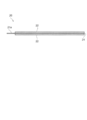
- FIG. 2 is a cross-sectional view taken along line AA of FIG. 1
- FIG. 3 is a cross-sectional view of the electrode.
- the battery electrode supply device 10 includes a magazine 11, a frame body 12, a brush 13 as a restricting portion, a pedestal 14, and a vacuum hand 15.
- the magazine 11 is a member that stacks and accommodates plate-like electrodes 20, and includes six guide shafts 16 that position the electrodes 20 and a stage 17 that carries the electrodes 20 and moves up and down.
- the magazine 11 has an opening 11 a formed at the upper end thereof surrounded by the upper end of the guide shaft 16.
- the guide shaft 16 is a columnar member extending upward from the pedestal 14 and is provided so as to come into contact with two sides each of the three sides which are outer edges of the electrode 20 excluding the terminal portion of the electrode 20.
- the guide shaft 16 is not limited to a columnar shape, and may be any shape such as a prismatic shape or a plate shape that is disposed along the vertical direction of the side surface (outer edge) of the stacked electrodes 20. Further, the number of guide shafts 16 is not limited, and at least one positioning shaft can be obtained by providing each one on any two adjacent sides of the electrode 20 excluding the terminal portion.
- the guide shaft 16 is not an essential component, and other members that support the frame body 12 may be used.
- the stage 17 is supported by an elevator (not shown) and can move up and down in the magazine 11. The most elevated position of the stage 17 is up to the lower end of the frame body 12. Then, as the electrode 20 is taken out from the magazine 11, the stage 17 rises, and the uppermost electrode 20 is always kept at the same height. Thus, the vacuum hand 15 can always take out the electrode 20 from the magazine 11 by performing a constant operation, and can also keep the speed at which the electrode 20 is supplied to the production line.
- the stage 17 is not an essential component, and for example, the electrode 20 may be loaded on the pedestal 14.
- the frame body 12 has a rectangular frame shape, and is provided so as to surround the vicinity of the opening 11a, that is, the vicinity of the upper end of the guide shaft 16.
- the thickness of the frame body 12 can be designed in a range not exceeding the length of the guide shaft 16, but if it is too thin, a sufficient amount of the brush 13 cannot be provided.
- the frame 12 may be U-shaped, and in that case, the terminal portion side of the electrode 20 is opened.
- the frame 12 is not an essential configuration.
- the brush 13 is provided on the inner side of the frame 12 so as to protrude to the side surface of the electrode 20, and at least when the electrode 20 is taken out, it contacts the outer edge of the electrode 20 and has a role of separating the electrodes 20 that are in close contact with each other. ing.
- the brush 13 is provided so as to be in contact with all the outer edges of the electrode 20 except the terminal portion of the electrode 20. Note that the brush 13 does not necessarily need to be in contact with all the outer edges of the electrode 20 except for the terminal portion of the electrode 20, and even in the case where the brush 13 is provided at a position in contact with a part of the outer edge of the electrode 20 except for the terminal portion of the electrode 20 The effect is obtained.
- the brush 13 may be provided on a member other than the frame body 13.
- the reason why the brush 13 is not provided on the terminal portion side of the electrode 20 is that the terminal portion of the electrode 20 is soft, as will be described later, so that even if the terminal portion is covered with the brush 13, the adhesion between the electrodes 20 cannot be eliminated. It is.
- the material of the brush 13 a resin such as polyester can be used, and it is preferable to use conductive polyester from the viewpoint of countermeasures against static electricity.
- the brush 13 is grounded. If the length of the portion of the brush 13 that overlaps the electrode 20 is too short, the biasing is weak and the removal of a plurality of electrodes cannot be prevented, and if it is too long, the biasing is strong and one cannot be removed. It is desirable to set the degree.
- the electrode 20 Since the electrode 20 is manufactured by punching or slitting a roll electrode with a mold, burrs are likely to occur on the end surface.
- the burr is an active material on the surface of the electrode 20 and causes problems such as dendrite precipitation and short circuit when used as a battery. According to the brush 13, the burrs can be removed at the same time. If a location where burrs are likely to occur in the electrode 20 is known, the burrs can be effectively removed by arranging the brush 13 at that location.
- the pedestal 14 is a base of the supply device 10 and is a member having a size and a weight that can stably support the magazine 11.
- the vacuum hand 15 is a device that descends from above the magazine 11, sucks and takes out the uppermost electrode 20 from the opening 11a, and supplies the electrode 20 to the production line. Although only one vacuum hand 15 is shown in FIG. 1, a plurality of vacuum hands 15 may be used depending on the size of the electrode 20.
- the electrode 20 has an active material layer 22 on both surfaces of the current collector 21 except for the terminal portion 21a.
- an example of electrodes (positive electrode and negative electrode) of a stacked lithium ion secondary battery will be described.
- the positive electrode has a structure in which a positive electrode active material layer is supported on both sides of a positive electrode current collector.
- the positive electrode current collector has a function of collecting current from the positive electrode active material layer.
- the positive electrode current collector is made of, for example, a metal foil such as aluminum or titanium, or an alloy foil made of an alloy of these, and has a thickness of about 1 to 500 ⁇ m (for example, about 20 ⁇ m).
- a positive electrode electrical power collector aluminum is preferable and it is preferable that the thickness is 20 micrometers or less.
- a current collector in which a metal is coated on a resin can also be used.
- the positive electrode current collector has a film shape, a sheet shape, a net shape, a punched or expanded shape, a lath body, a porous body, a foamed body, a formed body of fiber groups, and the like. May be.
- the positive electrode active material layer includes a positive electrode active material capable of inserting and extracting lithium ions.
- a positive electrode active material the oxide containing lithium is mentioned, for example. Specific examples include LiCoO 2 , LiFeO 2 , LiMnO 2 , LiMn 2 O 4 , and compounds in which transition metals in these oxides are partially substituted with other metal elements. Among these, in a normal use, it is preferable to use a material that can utilize 80% or more of the amount of lithium held by the positive electrode for the battery reaction.
- Examples of such a positive electrode active material include a compound having a spinel structure such as LiMn 2 O 4 and LiMPO 4 (M is at least one element selected from Co, Ni, Mn, and Fe). Examples thereof include compounds having an olivine structure. Among these, a positive electrode active material containing at least one of Mn and Fe is preferable from the viewpoint of cost. Furthermore, it is preferable to use LiFePO 4 from the viewpoint of safety and charging voltage. In LiFePO 4 , since all oxygen (O) is bonded to phosphorus (P) by a strong covalent bond, release of oxygen due to a temperature rise hardly occurs. Therefore, it is excellent in safety.
- the thickness of the positive electrode active material layer is preferably about 20 ⁇ m to 2 mm, and more preferably about 50 ⁇ m to 1 mm.
- the configuration of the positive electrode active material layer is not particularly limited as long as it includes at least the positive electrode active material.
- the positive electrode active material layer may include other materials such as a conductive material, a thickener, and a binder in addition to the positive electrode active material.
- the positive electrode described above is, for example, a mixture of a positive electrode active material, a conductive material, a thickener and a binder, and an appropriate solvent added to form a paste-like positive electrode mixture on the surface of the positive electrode current collector. Dried and compressed to increase electrode density as needed.
- the positive electrode has a rectangular shape when seen in a plan view.
- the width in the short direction is, for example, about 150 mm
- the length in the longitudinal direction is, for example, about 320 mm.
- the application area (formation area) of the positive electrode active material layer is the same as the width of the positive electrode current collector in the short direction, for example, about 150 mm
- the length in the longitudinal direction is, for example, about 300 mm. ing.
- the positive electrode has, at one end in the longitudinal direction, a terminal portion that is a current collector exposed portion where the surface of the positive electrode current collector is exposed without forming the positive electrode active material layer.
- a current collecting lead (not shown) for extracting a current to the outside is electrically connected to the terminal portion.
- the negative electrode has a configuration in which a negative electrode active material layer is supported on both surfaces of a negative electrode current collector.
- the negative electrode current collector has a function of collecting current from the negative electrode active material layer.
- the negative electrode current collector is made of, for example, a metal foil such as copper, nickel, stainless steel, iron, or a nickel plating layer, or an alloy foil made of these alloys, and has a thickness of about 1 ⁇ m to about 100 ⁇ m (for example, about 16 ⁇ m). ).
- the negative electrode current collector is preferably a metal foil made of copper or stainless steel, and the thickness is preferably 4 ⁇ m or more and 20 ⁇ m or less.
- a current collector in which a metal is coated on a resin can also be used.
- the negative electrode current collector has a film shape, a sheet shape, a net shape, a punched or expanded shape, a lath body, a porous body, a foamed body, a formed body of fiber groups, and the like. May be.
- the negative electrode active material layer includes a negative electrode active material that can occlude and release lithium ions.
- a negative electrode active material for example, a material containing lithium or a material capable of occluding and releasing lithium is used.
- the potential for insertion / extraction of lithium is close to the deposition / dissolution potential of metallic lithium.
- Typical examples thereof include particulate natural graphite or artificial graphite (scale-like, lump-like, fibrous, whisker-like, spherical, pulverized particle-like, etc.).
- the negative electrode active material artificial graphite obtained by graphitizing mesocarbon microbeads, mesophase pitch powder, isotropic pitch powder, or the like may be used. Further, graphite particles having amorphous carbon attached to the surface can also be used. Furthermore, lithium transition metal oxides, lithium transition metal nitrides, transition metal oxides, silicon oxides, and the like can also be used. As the lithium transition metal oxide, for example, when lithium titanate typified by Li 4 Ti 5 O 12 is used, the deterioration of the negative electrode is reduced, so that the life of the battery can be extended.
- the thickness of the negative electrode active material layer is preferably about 20 ⁇ m to 2 mm, and more preferably about 50 ⁇ m to 1 mm.
- the structure of the negative electrode active material layer is not particularly limited as long as it includes at least the negative electrode active material.
- the negative electrode active material layer may include other materials such as a conductive material, a thickener, and a binder in addition to the negative electrode active material.
- the negative electrode described above is, for example, a mixture of a negative electrode active material, a conductive material, a thickener, and a binder, and an appropriate solvent added to form a paste-like negative electrode mixture on the surface of the negative electrode current collector. Dried and compressed to increase electrode density as needed.
- the negative electrode has a rectangular shape when seen in a plan view. Moreover, the said negative electrode is formed in the plane area larger than a positive electrode.
- the negative electrode has a width in the short side direction larger than that of the positive electrode, for example, about 154 mm, and a length in the longitudinal direction longer than that of the positive electrode, for example, about 324 mm.
- the negative electrode active material layer application region (formation region) has a width in the short direction equal to the width of the negative electrode current collector, for example, about 154 mm, and a length in the longitudinal direction is, for example, about It is set to 304 mm. For this reason, the negative electrode active material layer formed in the application region is formed in a rectangular shape when seen in a plan view.
- the negative electrode has, at one end in the longitudinal direction, a terminal portion that is a current collector exposed portion where the surface of the negative electrode current collector is exposed without forming the negative electrode active material layer.
- a current collecting lead (not shown) for extracting a current to the outside is electrically connected to the terminal portion.
- the operation of the supply device 10 will be described.
- the vacuum hand 15 descends and is attracted to the upper surface of the uppermost electrode 20.
- the vacuum hand 15 is raised, and the attracted electrode 20 is taken out from the opening 11 a of the magazine 11, that is, the frame body 12.
- the outer edge of the electrode 20 comes into contact with the brush 13 from below while resisting the urging force of the brush 13, and passes through the frame 12 while pushing the brush 13 away.
- the vacuum hand 15 may be moved up and down a plurality of times at a position including the inside of the frame 12 after attracting the electrode 20, and the electrode 20 may come into contact with the brush 13 during the lifting and lowering. Thereby, the separation of the electrode 20 is further ensured, and the effect of deburring is also improved.
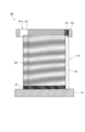
- FIG. 4 is a perspective view of the battery electrode supply device 30 according to an embodiment of the present invention.
- the same members as those in FIG. 1 are denoted by the same reference numerals, and detailed description thereof is omitted.
- the battery electrode supply device 30 is different from the above-described supply device 10 in that the magazine 31 is surrounded by a frame 32.
- the guide shaft 16 is not provided in FIG. 4, it may be provided.
- the frame 32 is a U-shaped member with a flat cross section provided from the opening 31 a of the magazine 31 to the lower end of the magazine 31.
- the electrode 20 can be supplied to the magazine 31 from the opening on the side surface of the frame 32. In that case, the terminal part of an electrode is arrange
- a door may be provided on the opening surface, and the door may be opened and closed when the electrode 20 is supplied to the magazine 31.
- the brush 33 is provided inside the frame body 32 so as to protrude to the side surface of the electrode 20, and has a role of touching the outer edges of the electrode 20 at least when the electrode 20 is taken out and separating the electrodes 20 that are in close contact with each other. ing.
- the brush 33 is provided in contact with all the outer edges of the electrode 20 except for the terminal portions of the stacked electrodes 20. That is, the brush 33 is provided from the upper end to the lower end of the frame body 32.
- the brush 33 is not necessarily in contact with the entire outer edge of the electrode 20 except for the terminal portion of the electrode 20, and the present invention is provided even when the brush 33 is provided at a position in contact with a part of the outer edge of the electrode 20 except for the terminal portion of the electrode 20. The effect is obtained.
- the material and length of the brush 33 can be the same as those of the brush 33 described above.
- the uppermost electrode 20 is maintained at a fixed position by the movement of the stage 17.
- the vacuum hand 15 descends and is attracted to the upper surface of the uppermost electrode 20.
- the vacuum hand 15 is raised, and the attracted electrode 20 is taken out from the opening 31 a of the magazine 31, that is, the frame body 32.
- the outer edge of the electrode 20 contacts the brush 33 while resisting the urging force of the brush 33, and passes through the frame 12 while pushing the brush 33 away.
- the burr of the electrode 20 is also removed by the brush 33. Further, the burr of the electrode 20 is removed when the stage 17 is moved.
- the vacuum hand 15 may move up and down a plurality of times within the frame 32 after attracting the electrode 20, and the electrode 20 may come into contact with the brush 13 during the lifting and lowering. Thereby, the separation of the electrode 20 is further ensured, and the effect of deburring is also improved.
- FIG. 5 is a cross-sectional view of the battery electrode supply device 40 according to an embodiment of the present invention.
- the same members as those in FIG. 2 are denoted by the same reference numerals, and detailed description thereof is omitted.
- the battery electrode supply device 40 is different from the above-described supply device 10 in that a protruding portion 43 is used instead of the brush 13 as a regulating portion.
- a plurality of protrusions 43 are arranged in parallel with the outer edge of the electrode 20.
- the protrusion 43 is a triangular prism member, and is provided in a plurality of stages horizontally on the inner side of the frame body 12 so that one top side protrudes to the side surface of the electrode 20. In other words, it can be said that a plurality of protrusions 43 are arranged side by side, so that grooves due to irregularities are formed.
- the protrusion 43 has a role which contacts the outer edge of the electrode 20 at the time of taking out the electrode 20 at least, and discriminates the electrodes 20 which are closely_contact
- the cross-sectional shape of the protrusion 43 is not limited to a triangle, but may be a polygon such as a quadrangle or a shape whose tip is an arc. Moreover, although the protrusion part 43 should just be arranged at least 2 or more in parallel, an effect is so large that the number is large.
- the protrusion 43 is provided so as to be in contact with all the outer edges of the electrode 20 except for the terminal portion of the electrode 20.
- the protrusion 43 does not necessarily need to be in contact with the entire outer edge of the electrode 20 except for the terminal portion of the electrode 20, and even when provided at a position in contact with a part of the outer edge of the electrode 20 except for the terminal portion of the electrode 20.
- the effect of the present invention can be obtained.
- the material of the protrusion 43 and the length of the protrusion can be the same as those of the brush 13 described above.
- the uppermost electrode 20 is kept in contact with the ridge 43 by the movement of the stage 17, or the uppermost electrode 20 is positioned below the ridge 43. Kept in a state. In this state, the vacuum hand 15 descends and is attracted to the upper surface of the uppermost electrode 20. Thereafter, the vacuum hand 15 is raised, and the attracted electrode 20 is taken out from the opening 41 a of the magazine 41, that is, the frame body 12. At this time, the outer edge of the electrode 20 comes into contact with the protrusion 43 from below while resisting the urging force of the protrusion 43, and passes through the frame 12 while pushing the protrusion 43 away.
- the vacuum hand 15 may be moved up and down a plurality of times at a position including the inside of the frame 12 after the electrode 20 is sucked, and the electrode 20 may contact the protrusion 43 during the lifting and lowering. Thereby, the separation of the electrode 20 is further ensured, and the effect of deburring is also improved.
- the present invention can be used for a supply device for supplying electrodes of various batteries including a secondary battery to a production line.
Landscapes
- Engineering & Computer Science (AREA)
- Chemical & Material Sciences (AREA)
- Manufacturing & Machinery (AREA)
- Chemical Kinetics & Catalysis (AREA)
- Electrochemistry (AREA)
- General Chemical & Material Sciences (AREA)
- Materials Engineering (AREA)
- Mechanical Engineering (AREA)
- Battery Electrode And Active Subsutance (AREA)
- Sheets, Magazines, And Separation Thereof (AREA)
- Secondary Cells (AREA)
Abstract
L'invention porte sur un dispositif d'alimentation (10) qui possède un magasin (11), un dispositif de manutention par dépression (15) et une brosse (13). Le magasin (11) reçoit des électrodes en forme de plaque empilées (20) et présente une ouverture (11a) sur l'extrémité supérieure. Le dispositif de manutention par dépression (15) saisit par plateau de maintien à vide les électrodes (20) et les retire à travers l'ouverture (11a). La brosse (13) vient en contact avec le bord externe des électrodes (20). Le dispositif de manutention par dépression (15) élève et abaisse les électrodes saisies par plateau de maintien à vide (20) une pluralité de fois, et frotte par conséquent le bord externe des électrodes (20) contre la brosse. Des paires d'électrodes (20) adhérant étroitement sont par conséquent séparées, et des électrodes uniques (20) peuvent être retirées par le plateau de maintien à vide (15). En même temps, des bavures sur le bord externe de l'électrode (20) sont éliminées par frottement par la brosse (13).
Applications Claiming Priority (2)
| Application Number | Priority Date | Filing Date | Title |
|---|---|---|---|
| JP2012-016902 | 2012-01-30 | ||
| JP2012016902A JP2013157197A (ja) | 2012-01-30 | 2012-01-30 | 電池用電極の供給装置 |
Publications (1)
| Publication Number | Publication Date |
|---|---|
| WO2013114659A1 true WO2013114659A1 (fr) | 2013-08-08 |
Family
ID=48904727
Family Applications (1)
| Application Number | Title | Priority Date | Filing Date |
|---|---|---|---|
| PCT/JP2012/072692 Ceased WO2013114659A1 (fr) | 2012-01-30 | 2012-09-06 | Dispositif de fourniture d'électrode de pile |
Country Status (2)
| Country | Link |
|---|---|
| JP (1) | JP2013157197A (fr) |
| WO (1) | WO2013114659A1 (fr) |
Cited By (4)
| Publication number | Priority date | Publication date | Assignee | Title |
|---|---|---|---|---|
| CN103601014A (zh) * | 2013-11-20 | 2014-02-26 | 合肥凯邦电机有限公司 | 波形垫圈的放料装置 |
| WO2016002798A1 (fr) * | 2014-06-30 | 2016-01-07 | エリーパワー株式会社 | Appareil de fourniture de plaque d'électrode de cellule secondaire, et procédé de commande dudit appareil |
| CN111816931A (zh) * | 2019-11-29 | 2020-10-23 | 合肥国轩高科动力能源有限公司 | 一种叠片电池连续生产装置 |
| CN114148756A (zh) * | 2022-02-08 | 2022-03-08 | 徐州申通木业有限公司 | 一种板材生产制造自动化上料机 |
Families Citing this family (11)
| Publication number | Priority date | Publication date | Assignee | Title |
|---|---|---|---|---|
| JP6344159B2 (ja) * | 2014-09-01 | 2018-06-20 | 株式会社豊田自動織機 | 電極組立体の製造方法 |
| JP6544195B2 (ja) * | 2015-10-23 | 2019-07-17 | 株式会社村田製作所 | 電極箔の搬送装置および積層型電池の製造装置 |
| JP6819850B2 (ja) * | 2016-06-01 | 2021-01-27 | 大日本印刷株式会社 | 枚葉紙持ち上げ装置および枚葉紙持ち上げ方法 |
| KR101818076B1 (ko) | 2016-08-04 | 2018-01-12 | 안혁 | 이차전지 셀 적층용 매거진 |
| CN106429431A (zh) * | 2016-10-19 | 2017-02-22 | 无锡百立德自动化有限公司 | 锂电池电芯叠片机极片上料装置 |
| JP7750138B2 (ja) * | 2022-02-24 | 2025-10-07 | トヨタ紡織株式会社 | 電極搬出装置 |
| JP7808275B2 (ja) * | 2022-02-24 | 2026-01-29 | トヨタ紡織株式会社 | 電極搬出装置 |
| KR20240102429A (ko) * | 2022-12-26 | 2024-07-03 | 주식회사 엘지에너지솔루션 | 전극 공급 장치, 이를 이용하는 전극 조립체 제조 장치, 전극 공급 방법 및 이를 이용하는 전극 조립체 제조 방법 |
| KR20250133273A (ko) * | 2023-01-09 | 2025-09-05 | 엘지전자 주식회사 | 전지셀 흡착 장치 및 방법 |
| WO2025057531A1 (fr) * | 2023-09-15 | 2025-03-20 | 富士フイルム株式会社 | Dispositif auxiliaire pour un dispositif de transport et procédé de fabrication d'une plaque d'impression planographique |
| CN117303045A (zh) * | 2023-11-02 | 2023-12-29 | 永成(新加坡)包装研发私人有限公司 | 物料袋分离机构、物料袋分离装置和供袋机 |
Citations (3)
| Publication number | Priority date | Publication date | Assignee | Title |
|---|---|---|---|---|
| JPS5719243A (en) * | 1980-07-10 | 1982-02-01 | Iwatsu Electric Co Ltd | Automatic paper feeder for duplicator |
| JPS6439334U (fr) * | 1987-09-02 | 1989-03-09 | ||
| JP2001313065A (ja) * | 2000-05-01 | 2001-11-09 | Toshiba Battery Co Ltd | 電池用電極シートの供給装置 |
-
2012
- 2012-01-30 JP JP2012016902A patent/JP2013157197A/ja active Pending
- 2012-09-06 WO PCT/JP2012/072692 patent/WO2013114659A1/fr not_active Ceased
Patent Citations (3)
| Publication number | Priority date | Publication date | Assignee | Title |
|---|---|---|---|---|
| JPS5719243A (en) * | 1980-07-10 | 1982-02-01 | Iwatsu Electric Co Ltd | Automatic paper feeder for duplicator |
| JPS6439334U (fr) * | 1987-09-02 | 1989-03-09 | ||
| JP2001313065A (ja) * | 2000-05-01 | 2001-11-09 | Toshiba Battery Co Ltd | 電池用電極シートの供給装置 |
Cited By (7)
| Publication number | Priority date | Publication date | Assignee | Title |
|---|---|---|---|---|
| CN103601014A (zh) * | 2013-11-20 | 2014-02-26 | 合肥凯邦电机有限公司 | 波形垫圈的放料装置 |
| CN103601014B (zh) * | 2013-11-20 | 2016-08-24 | 合肥凯邦电机有限公司 | 波形垫圈的放料装置 |
| WO2016002798A1 (fr) * | 2014-06-30 | 2016-01-07 | エリーパワー株式会社 | Appareil de fourniture de plaque d'électrode de cellule secondaire, et procédé de commande dudit appareil |
| TWI645594B (zh) * | 2014-06-30 | 2018-12-21 | 日商艾利電力能源有限公司 | 二次電池的電極板的供給裝置及其控制方法 |
| CN111816931A (zh) * | 2019-11-29 | 2020-10-23 | 合肥国轩高科动力能源有限公司 | 一种叠片电池连续生产装置 |
| CN111816931B (zh) * | 2019-11-29 | 2022-09-13 | 合肥国轩高科动力能源有限公司 | 一种叠片电池连续生产装置 |
| CN114148756A (zh) * | 2022-02-08 | 2022-03-08 | 徐州申通木业有限公司 | 一种板材生产制造自动化上料机 |
Also Published As
| Publication number | Publication date |
|---|---|
| JP2013157197A (ja) | 2013-08-15 |
Similar Documents
| Publication | Publication Date | Title |
|---|---|---|
| WO2013114659A1 (fr) | Dispositif de fourniture d'électrode de pile | |
| CN101517815B (zh) | 锂二次电池的制造方法以及锂二次电池 | |
| CN101409339B (zh) | 电极组件和具有该电极组件的二次电池 | |
| EP2680361A1 (fr) | Assemblage d'électrodes de type roulé en gelée avec revêtement à motif de matériaux actifs sur celles-ci, et batterie secondaire le comprenant | |
| JP2011204660A (ja) | リチウム二次電池 | |
| CN104067435A (zh) | 非水电解质二次电池的制造方法和非水电解质二次电池 | |
| KR101610431B1 (ko) | 젤리롤 형태의 전극조립체 및 이를 포함하는 이차전지 | |
| EP4510202A1 (fr) | Ensemble électrode, élément de batterie, batterie et dispositif électrique | |
| JP2011070976A (ja) | リチウムイオン二次電池、車両及び電池搭載機器 | |
| CN217334332U (zh) | 电极组件、电池单体、电池及用电装置 | |
| WO2022198682A1 (fr) | Ensemble électrode, élément de batterie, batterie, et procédé et dispositif de fabrication d'ensemble électrode | |
| CN111801831A (zh) | 包括磁体的按压夹具和包括该按压夹具的电池模块 | |
| US12160009B2 (en) | Battery cell, method and system for manufacturing same, battery, and electrical device | |
| JP7761637B2 (ja) | 電極アセンブリ、電池セル、電池、並びに電極アセンブリを製造するための方法及びデバイス | |
| JP2023509174A (ja) | 電池セル、電池および電子装置 | |
| CN111799441B (zh) | 非水电解质二次电池 | |
| CN114730961B (zh) | 电化学装置及用电设备 | |
| JP2011222128A (ja) | 二次電池 | |
| CN102144319B (zh) | 锂离子二次电池及其制造方法 | |
| US20160049651A1 (en) | Negative electrode for nonaqueous electrolyte secondary battery and nonaqueous electrolyte secondary battery | |
| WO2002059986A2 (fr) | Electrode avec languette en forme de drapeau | |
| US9356294B2 (en) | Secondary battery including collectors with pores and manufacturing method thereof | |
| KR101431726B1 (ko) | 안전성이 향상된 전극조립체 및 이를 이용한 이차전지 | |
| KR101520345B1 (ko) | 입체형 전극 어셈블리 및 이의 제조 방법 | |
| JP6050954B2 (ja) | 非水電解質二次電池 |
Legal Events
| Date | Code | Title | Description |
|---|---|---|---|
| 121 | Ep: the epo has been informed by wipo that ep was designated in this application |
Ref document number: 12867134 Country of ref document: EP Kind code of ref document: A1 |
|
| NENP | Non-entry into the national phase |
Ref country code: DE |
|
| 122 | Ep: pct application non-entry in european phase |
Ref document number: 12867134 Country of ref document: EP Kind code of ref document: A1 |