WO2013114701A1 - Dispositif de lentille et dispositif de prise de vues - Google Patents
Dispositif de lentille et dispositif de prise de vues Download PDFInfo
- Publication number
- WO2013114701A1 WO2013114701A1 PCT/JP2012/079403 JP2012079403W WO2013114701A1 WO 2013114701 A1 WO2013114701 A1 WO 2013114701A1 JP 2012079403 W JP2012079403 W JP 2012079403W WO 2013114701 A1 WO2013114701 A1 WO 2013114701A1
- Authority
- WO
- WIPO (PCT)
- Prior art keywords
- magnet
- drive unit
- magnetic
- lens barrel
- lens
- Prior art date
- Legal status (The legal status is an assumption and is not a legal conclusion. Google has not performed a legal analysis and makes no representation as to the accuracy of the status listed.)
- Ceased
Links
Images




Classifications
-
- G—PHYSICS
- G02—OPTICS
- G02B—OPTICAL ELEMENTS, SYSTEMS OR APPARATUS
- G02B7/00—Mountings, adjusting means, or light-tight connections, for optical elements
- G02B7/02—Mountings, adjusting means, or light-tight connections, for optical elements for lenses
- G02B7/04—Mountings, adjusting means, or light-tight connections, for optical elements for lenses with mechanism for focusing or varying magnification
- G02B7/10—Mountings, adjusting means, or light-tight connections, for optical elements for lenses with mechanism for focusing or varying magnification by relative axial movement of several lenses, e.g. of varifocal objective lens
- G02B7/102—Mountings, adjusting means, or light-tight connections, for optical elements for lenses with mechanism for focusing or varying magnification by relative axial movement of several lenses, e.g. of varifocal objective lens controlled by a microcomputer
-
- H—ELECTRICITY
- H04—ELECTRIC COMMUNICATION TECHNIQUE
- H04N—PICTORIAL COMMUNICATION, e.g. TELEVISION
- H04N23/00—Cameras or camera modules comprising electronic image sensors; Control thereof
- H04N23/50—Constructional details
- H04N23/55—Optical parts specially adapted for electronic image sensors; Mounting thereof
-
- G—PHYSICS
- G03—PHOTOGRAPHY; CINEMATOGRAPHY; ANALOGOUS TECHNIQUES USING WAVES OTHER THAN OPTICAL WAVES; ELECTROGRAPHY; HOLOGRAPHY
- G03B—APPARATUS OR ARRANGEMENTS FOR TAKING PHOTOGRAPHS OR FOR PROJECTING OR VIEWING THEM; APPARATUS OR ARRANGEMENTS EMPLOYING ANALOGOUS TECHNIQUES USING WAVES OTHER THAN OPTICAL WAVES; ACCESSORIES THEREFOR
- G03B13/00—Viewfinders; Focusing aids for cameras; Means for focusing for cameras; Autofocus systems for cameras
- G03B13/32—Means for focusing
- G03B13/34—Power focusing
-
- G—PHYSICS
- G03—PHOTOGRAPHY; CINEMATOGRAPHY; ANALOGOUS TECHNIQUES USING WAVES OTHER THAN OPTICAL WAVES; ELECTROGRAPHY; HOLOGRAPHY
- G03B—APPARATUS OR ARRANGEMENTS FOR TAKING PHOTOGRAPHS OR FOR PROJECTING OR VIEWING THEM; APPARATUS OR ARRANGEMENTS EMPLOYING ANALOGOUS TECHNIQUES USING WAVES OTHER THAN OPTICAL WAVES; ACCESSORIES THEREFOR
- G03B17/00—Details of cameras or camera bodies; Accessories therefor
- G03B17/56—Accessories
-
- H—ELECTRICITY
- H04—ELECTRIC COMMUNICATION TECHNIQUE
- H04N—PICTORIAL COMMUNICATION, e.g. TELEVISION
- H04N23/00—Cameras or camera modules comprising electronic image sensors; Control thereof
- H04N23/60—Control of cameras or camera modules
- H04N23/66—Remote control of cameras or camera parts, e.g. by remote control devices
- H04N23/663—Remote control of cameras or camera parts, e.g. by remote control devices for controlling interchangeable camera parts based on electronic image sensor signals
Definitions
- the present invention relates to a lens apparatus including a drive unit for electrically rotating an operation ring of a lens barrel, and an imaging apparatus including the lens apparatus.
- a drive unit for electrically rotating an operation ring such as a zoom ring provided on the lens barrel may be attached to the outer periphery of the lens barrel. Yes (see, for example, Patent Document 1).
- the drive unit includes a motor, a speed reduction mechanism that transmits the rotational torque of the motor to the operation ring, a potentiometer that detects the rotation angle of the operation ring, and the like. Then, the drive unit drives the motor until the rotation angle detected by the potentiometer reaches the rotation angle corresponding to the command signal input from the external controller.
- the drive unit described in Patent Document 1 is divided into a drive unit including a motor, a speed reduction mechanism, and the like, and an operation unit configured as a grip including a controller.
- the drive unit and the operation unit are mutually attached by magnetic attraction. Fixed.
- the operation unit is attached to and detached from the drive unit in accordance with shooting conditions such as shooting with a shoulder or shooting with a tripod fixed.
- the entire drive unit including the drive unit may be removed from the lens barrel.
- the drive unit is typically screw-fixed to a lens barrel at a plurality of locations, the drive unit is not easily attached to and detached from the lens barrel.
- Patent Document 1 In the drive unit described in Patent Document 1, the operation unit is fixed to the drive unit by magnetic adsorption, and the operation unit is relatively easy to attach to and detach from the drive unit.
- Patent Document 1 does not mention a method for fixing the drive unit to the lens barrel. However, if the entire drive unit including the drive unit is fixed to the lens barrel by magnetic attraction, the drive unit is fixed to the lens barrel. Detachment is easy.
- the drive unit includes a motor, a speed reduction mechanism, and the like, and is heavier than the operation unit. Therefore, in order to fix the entire drive unit including the drive unit to the lens barrel by magnetic attraction, a correspondingly strong magnetic force is required.
- the strong magnetic force in the magnetic adsorption fixing may reduce the workability when removing the drive unit from the lens barrel.
- the present invention has been made in view of the above-described circumstances, and an object thereof is to facilitate attachment / detachment of a drive unit to / from a lens barrel.
- a lens barrel that houses an imaging optical system including at least one movable optical element and has an operating ring for adjusting the movable optical element, and a drive unit for driving the operating ring. And a drive unit attached to the outer periphery of the lens barrel.
- the drive unit is provided with a first magnet, and the drive unit is attached to the lens barrel on the outer periphery of the lens barrel.
- a magnetic body is provided at a portion facing the first magnet, and the drive unit can be attached to and detached from the lens barrel using the magnetic adsorption action of the first magnet and the magnetic body.
- the first magnet is fixed, and the first magnet is detached from the magnetic attraction with the magnetic body by displacing the magnetic attraction surface in a direction crossing the magnetic flux at the magnetic attraction surface.
- a lens device having a moving mechanism for moving the first magnet.
- the drive unit can be easily removed from the lens barrel.
- FIG. 3 is an exploded perspective view showing the drive unit of FIG. 2.
- FIG. 3 is a perspective view showing a fixing structure for the lens barrel of the drive unit of FIG. 2.
- It is a schematic diagram which shows the attachment or detachment process with respect to the lens barrel of the drive unit of FIG.
- It is a schematic diagram which shows the structure of the modification of the drive unit of FIG.
- It is a perspective view which shows the structure of the modification of the drive unit of FIG.
- FIG. 1 shows a configuration of an example of a lens device and an imaging device including the lens device for explaining an embodiment of the present invention.
- the imaging device 1 includes an imaging device body 2 having an imaging element such as a CCD image sensor, and a lens device 3A fixed to the imaging device body 2 so as to be detachable.
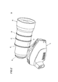
- the lens device 3 ⁇ / b> A includes a substantially cylindrical lens barrel 10 and a drive unit 11 attached to the outer periphery of the lens barrel 10.
- the drive unit 11 is also used as a grip for supporting the lens device 3A.
- the lens barrel 10 holds optical elements such as an iris and a lens such as a zoom lens and a focus lens, which form an optical system that forms an image on the image pickup device of the image pickup apparatus body 2.
- a mount 12 is provided at the base of the lens barrel 10.
- the lens device 3 ⁇ / b> A is fixed to the imaging device main body 2 by engaging a mount 12 with a lens mounting portion provided in the imaging device main body 2.
- the photographer H typically supports the imaging device 1 by holding the imaging device body 2 on the right shoulder and holding the drive unit 11 of the lens device 3A with the right hand 7.
- the photographer H photographs the subject by adjusting the zoom, focus, iris, etc. by operating the drive unit 11 with the right hand 7 holding the drive unit 11 while looking through the viewfinder 4 provided in the imaging apparatus body 2 with the right eye. Will do.
- FIG. 2 shows the external appearance of the lens device 3A.
- the lens barrel 10 includes a focus ring 20 for adjusting the focus, a zoom ring 21 for adjusting the zoom, and an iris ring 22 for adjusting the iris around the optical axis of the optical system housed in the lens barrel 10. It is provided rotatably.
- the focus lens is moved back and forth along the optical axis in conjunction with the rotation of the focus ring 20, the focus is adjusted, and the zoom lens is moved back and forth along the optical axis in conjunction with the rotation of the zoom ring 21 to adjust the zoom. Is done. Further, the iris blades are opened and closed in conjunction with the rotation of the iris ring 22 to adjust the iris.
- the exterior of the drive unit 11 is provided with various operation switches such as a seesaw switch 23 for adjusting zoom and a recording switch 24 for instructing ON / OFF of recording by the imaging apparatus 1.
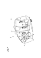
- FIG. 3 shows the internal configuration of the drive unit 11.
- the drive unit 11 is engaged with the motor 30, the speed reduction mechanism 31 that transmits the rotational torque of the motor 30 to the operation ring, the potentiometer 32 that detects the rotation angle of the operation ring, and the rotation angle detected by the potentiometer 32.
- the control part 33 which drives the motor 30 based on is comprised.
- the motor 30, the deceleration mechanism 31, and the potentiometer 32 are provided for every operation ring (the focus ring 20, the zoom ring 21, and the iris ring 22).
- the seesaw switch 23 is operated by the photographer H, and a command signal for instructing the rotation angle of the zoom ring 21 is input to the control unit 33 of the drive unit 11 according to the operation amount. The Then, the controller 33 drives the motor 30 until the rotation angle of the zoom ring 21 detected by the potentiometer 32 reaches the rotation angle corresponding to the command signal. Thereby, the zoom ring 21 is set to a desired rotation angle, and the zoom is adjusted.
- a command signal for instructing the rotation angle of the focus ring 20 or the iris ring 22 is externally supplied (for example, an autofocus control unit or an automatic exposure control unit provided in the imaging apparatus main body 2). Input to the control unit 33 of the drive unit 11. Then, the control unit 33 drives the motor 30 until the rotation angle of the focus ring 20 or the iris ring 22 detected by the potentiometer 32 reaches the rotation angle corresponding to the command signal.
- the drive unit 11 configured as described above is detachably fixed to a predetermined portion on the outer periphery of the lens barrel 10 using a magnetic adsorption action.
- a fixing structure of the drive unit 11 will be described.
- FIG. 4 shows a fixing structure of the drive unit 11.
- the drive unit 11 is provided with a magnet 40 for fixing the drive unit 11 to the lens barrel 10.
- a window 41 is formed on the exterior forming the joint surface of the drive unit 11 with the lens barrel 10, and the magnet 40 is exposed through the window 41.
- the magnet 40 is formed to be curved in a circular arc shape in cross section, and is in close contact with the outer periphery of the lens barrel 10 when the drive unit 11 is attached to the lens barrel 10.
- an attracted member 42 made of a ferromagnetic material such as iron is embedded in a portion facing the magnet 40 of the drive unit 11 in a state where the drive unit 11 is attached to the lens barrel 10 ( (See FIG. 2).
- the magnet 40 has a magnetic pole formed on at least a surface (hereinafter referred to as a magnetic attracting surface) 40a that is in close contact with the outer periphery of the barrel 10.
- the drive unit 11 attached to the lens barrel 10 is fixed to the lens barrel 10 by a magnetic attraction between the magnet 40 and the attracted member 42 of the lens barrel 10.
- the form of magnetization of the magnet 40 is not particularly limited as long as the attracted member 42 can be attracted.
- the magnet 40 has an attracting position P1 facing the attracted member 42 of the lens barrel 10 and a non-adsorbed position P2 deviating from the attracted member 42 in the optical axis direction which is one direction in the plane of the magnetic attracting surface 40a. It is provided so that translational movement is possible.
- the drive unit 11 is also provided with a guide portion that supports the magnet 40 so as to be capable of translational movement along the optical axis.
- An operation knob 43 connected to the magnet 40 is provided on the exterior of the drive unit 11.
- the magnet 40 moves between the suction position P1 and the non-attraction position P2 along the optical axis following the movement of the operation knob 43.
- an engaging portion 54 that engages the lens barrel 10 is provided on the exterior of the drive unit 11, and an engaged portion 55 that engages the engaging portion 54 is provided on the outer periphery of the lens barrel 10. It has been.
- the engaging portion 54 of the drive unit 11 is configured as a convex portion
- the engaging portion 55 of the lens barrel 10 is configured as a concave portion.
- the drive unit 11 is prevented from moving in the circumferential direction with the optical axis as the central axis and the optical axis direction with respect to the lens barrel 10.
- the form of the engaging portion 54 and the engaged portion 55 is not particularly limited as long as it can prevent the drive unit 11 from moving in the circumferential direction and the optical axis direction with respect to the lens barrel 10.
- FIG. 5 shows a process in which the drive unit 11 is attached to and detached from the lens barrel 10.
- the magnet 40 of the drive unit 11 is disposed at the attracting position P1, and the magnet 40 is magnetically attracted to the attracted member 42 of the lens barrel 10 (FIG. 5A).
- the operation knob 43 is moved along the optical axis, and the magnet 40 follows the movement of the operation knob 43 and moves from the adsorption position P1 to the non-adsorption position P2 along the optical axis. (FIG. 5B).
- the magnet 40 When the magnet 40 reaches the non-attraction position P2, the magnetic attraction between the magnet 40 and the attracted member 42 is substantially lost or weak, and the drive unit 11 is removed from the lens barrel 10. (FIG. 5C).
- the force required to move the magnet so that the magnetic attracting surface is displaced in a direction intersecting with the magnetic flux on the magnetic attracting surface is This is smaller than the force required to move the magnet in the normal direction.
- the magnet 40 In the movement from the attracting position P1 to the non-attracting position P2, the magnet 40 is moved in the optical axis direction which is one direction in the surface of the magnetic attracting surface 40a, that is, in a direction crossing the magnetic flux ⁇ on the magnetic attracting surface 40a.
- the magnetic attracting surface 40a is moved so as to be displaced. Accordingly, the force F1 required to move the magnet 40 from the attraction position P1 to the non-attraction position P2 causes the magnet 40 at the attraction position P1 and magnetically attracted to the attracted member 42 to be normal to the magnetic attraction surface 40a.
- the force F2 is smaller than the force F2 required for moving in the direction and peeling from the attracted member 42.
- the drive unit 11 can be easily detached from the lens barrel 10 by moving the magnet 40 from the attracting position P1 to the non-attracting position P2 and detaching the magnet 40 from the magnetic attraction with the attracted member 42.
- the magnet 40 When the drive unit 11 is attached to the lens barrel 10, the magnet 40 may be disposed at the non-adsorption position P ⁇ b> 2, and in that case, the magnet 40 is attracted by the attractive force generated between the attracted member 42. It is moved toward the position P1, and is magnetically attracted to the attracted member 42. However, it is preferable that the magnet 40 is disposed at the attracting position P ⁇ b> 1 facing the attracted member 42.
- an urging member 44 such as a spring is used to urge the magnet 40 from the non-adsorption position P2 toward the adsorption position P1.
- the magnet 40 arranged at the non-adsorption position P2 is automatically urged to the adsorption position P1 by being urged by the urging member 44 as the operation knob 43 is released.
- the drive unit 11 is provided with the magnet 40 and the lens barrel 10 is provided with the member to be attracted 42 that is a magnetic body, and the magnetic attraction action between the magnet 40 and the member to be attracted 42 is utilized.
- the drive unit 11 is detachably fixed to the lens barrel 10 so that the drive unit 11 can be easily attached and detached.
- the magnet 40 is moved so that the magnetic attracting surface 40a is displaced in a direction intersecting with the magnetic flux ⁇ on the magnetic attracting surface 40a of the magnet 40, and the magnet 40 is separated from the magnetic attracting with the attracted member 42.
- the force required for separating the magnet 40 from the magnetic attraction with the attracted member 42 can be reduced. Thereby, the drive unit 11 can be easily detached from the lens barrel 10.
- the magnet 40 When the magnet 40 is separated from the magnetic attraction with the attracted member 42, the magnet 40 may be moved in a circumferential direction around the optical axis that is one direction in the magnetic attraction surface 40a. Good. Also in this case, the magnetic attraction surface 40a is displaced in a direction intersecting with the magnetic flux ⁇ on the magnetic attraction surface 40a, and the force required for releasing the magnet 40 from the magnetic attraction with the attracted member 42 can be reduced.
- FIG. 6 shows a modification of the lens device 3A described above.
- a magnet 50 that is a hard magnetic material is embedded in the lens barrel 10 at a portion facing the magnet 40 of the drive unit 11.
- the magnet 40 of the drive unit 11 is magnetized in multiple poles at least on the magnetic attracting surface 40a, and in the illustrated example, a pair of N poles and S poles are formed side by side in the optical axis direction.
- the magnet 50 of the lens barrel 10 is also magnetized in multiple poles at least on the magnetic attracting surface 50a in the same manner as the magnet 40. In the illustrated example, a pair of N poles and S poles are arranged in the optical axis direction. Is formed.
- the arrangement of the N pole and the S pole on the magnetic adsorption surface 50a of the magnet 50 is set opposite to the arrangement of the N pole and the S pole on the magnetic adsorption surface 40a of the magnet 40.
- the south pole of the magnetic attracting surface 50a of the magnet 50 faces the north pole of the magnet attracting surface 40a of the magnet 40
- the south pole of the magnet 50 faces the south pole of the magnetic attracting surface 40a of the magnet 40.
- the N poles on the magnetic attraction surface 50a face each other. Thereby, the magnet 40 and the magnet 50 produce an attractive force between them, and are magnetically attracted to each other.
- the non-attraction position P2 is the distance from the attraction position P1 to the optical axis direction by a distance substantially corresponding to the width of one magnetic pole on the magnetic attraction surface 40a (in this example, half the length of the magnet 40 with respect to the optical axis direction). It is set at a position shifted to.
- the magnet 40 is at the non-attraction position P ⁇ b> 2
- the S poles (or the N poles) of the magnetic attraction surface 40 a of the magnet 40 and the magnetic attraction surface 50 a of the magnet 50 face each other, and the magnet 40 is magnetic with the magnet 50.
- the magnet is separated from the adsorption, and a repulsive force is generated between the magnet 50 and the magnet 50.
- the non-adsorption position P2 is set to a position where the magnet 40 is removed from the attracted member 42 in the optical axis direction, and the moving distance of the magnet 40 from the adsorption position P1 to the non-adsorption position P2 is the optical axis.
- the moving distance of the magnet 40 from the suction position P1 to the non-attraction position P2 is the length of the magnet 40 in the optical axis direction as described above. This corresponds to approximately half of the distance, and the moving distance of the magnet 40 can be shortened.
- the engaging portion 54 of the drive unit 11 is configured as a substantially L-shaped hook.
- the drive unit 11 has a circumferential direction and an optical axis direction centered on the optical axis with respect to the lens barrel 10, and further, the optical axis is the central axis. Movement in the radial direction is prevented.
- the magnet 40 of the drive unit 11 is disposed at the attracting position P1, and the magnet 40 is magnetically attracted to the magnet 50 of the lens barrel 10 (FIG. 6A).
- the operation knob 43 is moved along the optical axis, and the magnet 40 follows the movement of the operation knob 43 and moves from the adsorption position P1 to the non-adsorption position P2 along the optical axis. (FIG. 6B).
- the repulsive force generated between the magnet 40 and the magnet 50 acts on the drive unit 11 so that the drive unit 11 is separated from the lens barrel 10 in the radial direction with the optical axis as the central axis.
- the engaging portion 54 of the drive unit 11 is engaged with the engaged portion 55 of the lens barrel 10, and the drive unit 11 is fastened to the lens barrel 10 against the above repulsive force. This prevents the drive unit 11 from being inadvertently detached from the lens barrel 10.
- the engagement / disengagement direction of the engagement portion 54 with respect to the engaged portion 55 is set in the same optical axis direction as the movement direction of the magnet 40. Is preferably opposite to the moving direction of the magnet 40 from the attraction position P1 toward the non-attraction position P2.
- the repulsive force generated between the magnet 40 and the magnet 50 may act on the drive unit 11 so as to move the drive unit 11 in the moving direction of the magnet 40 from the attraction position P1 toward the non-attraction position P2.
- the engagement / disengagement direction of the engagement portion 54 with respect to the engaged portion 55 is set as described above, the engagement between the engagement portion 54 and the engaged portion 55 is reliably maintained.
- the engagement / disengagement direction of the engagement portion 54 with respect to the engaged portion 55 can be set to a circumferential direction centering on the optical axis.
- the drive unit 11 is moved in a direction in which the engaging portion 54 and the engaged portion 55 are disengaged (FIG. 6C), and the drive unit 11 is removed from the lens barrel 10 (FIG. 6D).
- each of the N pole and the S pole of the magnet 40 may generate an attractive force between the S pole and the N pole of the magnet 50 facing diagonally. This attractive force acts on the magnet 40 so as to move the magnet 40 from the non-attraction position P2 toward the attraction position P1.
- the drive unit 11 is provided with a holding portion 51 for holding the magnet 40 moved to the attracting position P1 or the non-attracting position P2 at that position.
- the holding portion 51 includes a locking claw 52 fixed to the magnet 40 and a claw receiving portion 53 that is provided in the drive unit 11 with the position in the drive unit 11 unchanged and engages with the locking claw 52.
- the holding portion 51 can prevent the magnet 40 from moving due to the above-described attractive force, thereby preventing the magnet 40 and the magnet 50 from being inadvertently magnetically attracted and preventing the drive unit 11 from being removed. can do.
- FIG. 7 shows a modification of the lens device 3A described above.
- an insulator 60 is used to move the magnet 40 from the attraction position P1 to the non-attraction position P2.
- the insulator 60 is pivotally supported at an intermediate portion in the longitudinal direction, and is configured to be rotatable in a plane parallel to the optical axis.
- An operation button 61 that is pushed in in the optical axis direction is provided on the exterior of the drive unit 11, and the operation button 61 is connected to one end of the lever 60.
- Magnet 40 is connected to the other end of insulator 60.
- the insulator 60 rotates accordingly, and the magnet 40 moves from the suction position P1 to the non-attraction position P2 along the optical axis.
- the distance L1 from the fulcrum PP of the lever 60 to the force point EP to which the operation button 61 is connected is set larger than the distance L2 from the fulcrum PP to the action point LP to which the magnet 40 is connected. Accordingly, the force applied to the operation button 61 is amplified by the lever 60 and transmitted to the magnet 40. Therefore, when moving the magnet 40 from the attraction position P1 to the non-attraction position P2, the force required for the operation can be further reduced.
- the structure which moves the magnet 40 using the insulator 60 is also provided in the lens apparatus 3B in which the magnet 50 is provided in the lens barrel 10 and the magnets 40 and 50 are magnetized in multiple poles on their magnetic adsorption surfaces. Applicable.
- the operation amount of the operation button 61 is larger than the movement distance of the magnet 40 from the attracting position P1 to the non-attracting position P2.
- the moving distance of the magnet 40 can be shortened and the operation amount of the operation button 61 can also be reduced. Therefore, the configuration in which the magnet 40 is moved using the lever 60 is applied. It is suitable for.
- FIG. 8 shows another example of a lens device for explaining an embodiment of the present invention. Note that elements common to the lens apparatuses 3A to 3C described above are denoted by common reference numerals, and description thereof is omitted.
- the magnet 40 of the drive unit 11 is magnetized on both the magnetic attracting surface 40a and the back surface 40b opposite to the magnet attracting surface 40a. It is magnetized on both surfaces of the opposite back surface 50b.
- the magnet 40 is pivotally supported at a substantially central portion in the magnetization direction so as to be rotatable so as to invert the magnetic attracting surface 40a and the back surface 40b.
- An operation knob 143 connected to the magnet 40 is provided on the exterior of the drive unit 11. When the operation knob 43 is rotated around the rotation axis A of the magnet 40, the magnet 40 rotates following the rotation of the operation knob 43.
- the attracting position P1 of the magnet 40 is a rotational position where the magnetic attracting surface 40a is opposed to the magnetic attracting surface 50a of the magnet 50, and the non-adsorbing position P2 is opposed to the magnetic attracting surface 50a of the magnet 50.
- This is a rotational position to be rotated, and is a position rotated 180 degrees from the suction position P1.
- the magnet 40 of the drive unit 11 is disposed at the attracting position P1, and the magnet 40 is magnetically attracted to the magnet 50 of the lens barrel 10 (FIG. 8A).
- the operation knob 43 is rotated, and the magnet 40 follows the rotation of the operation knob 43 and rotates from the adsorption position P1 to the non-adsorption position P2.
- the magnetic attraction surface 40a is displaced in a direction intersecting with the magnetic flux ⁇ on the surface. (FIG. 8B).
- the back surface 40b of the magnet 40 which is the same magnetic pole, and the magnetic adsorption surface 50a of the magnet 50 face each other, and the magnet 40 and the magnet 50 generate a repulsive force therebetween.
- the drive unit 11 is moved in the direction in which the engaging portion 54 and the engaged portion 55 are disengaged (FIG. 8C), and the drive unit 11 is removed from the lens barrel 10 (FIG. 8D).
- the drive unit 11 and the lens barrel 10 are provided with the magnets 40 and 50, respectively, and the drive unit 11 is detachably fixed to the lens barrel 10 using the magnetic attraction action of the magnets 40 and 50. Therefore, the drive unit 11 can be easily attached and detached.
- the magnet 40 of the drive unit 11 is moved so that the magnetic adsorption surface 40a is displaced in a direction intersecting with the magnetic flux ⁇ on the magnetic adsorption surface 40a of the magnet 40, and the magnet 40 is removed from the magnetic adsorption with the magnet 50 of the lens barrel 10.
- the force required for separating the magnet 40 from the magnetic attraction with the magnet 50 can be reduced. Thereby, the drive unit 11 can be easily detached from the lens barrel 10.
- a lens barrel that houses an imaging optical system including at least one movable optical element and has an operating ring for adjusting the movable optical element, and a drive unit for driving the operating ring.
- a drive unit attached to the outer periphery of the lens barrel, wherein the drive unit is provided with a first magnet, and the lens barrel has the drive unit attached to the lens barrel.
- a magnetic body is provided at a portion facing the first magnet, and the drive unit can be attached to and detached from the lens barrel by utilizing a magnetic attraction between the first magnet and the magnetic body. The magnetic attraction surface is displaced in a direction intersecting with the magnetic flux at the magnetic attraction surface of the first magnet so that the first magnet is separated from the magnetic attraction with the magnetic body.
- a lens device having a moving mechanism for moving the first magnet.
- the magnetic body is a second magnet
- the first magnet moved by the moving mechanism is repulsive with the second magnet.
- Lens device that produces (3)
- each of the first magnet and the second magnet is magnetized in multiple directions in one direction within the surface at least on the magnetic attracting surface
- the moving mechanism is a lens device that moves the first magnet in the arrangement direction of the magnetic poles on the magnetic adsorption surface.
- the moving mechanism includes a lever
- the drive unit includes an operation unit that operates the moving mechanism.
- the fulcrum and the operation unit A lens device in which a first distance between the force points to which the first magnet is coupled is larger than a second distance between the fulcrum and the action point to which the first magnet is coupled.
- each of the first magnet and the second magnet is magnetized on both the magnetic attracting surface and the back surface thereof, and the moving mechanism is A lens device that rotates the first magnet so as to reverse the magnetic adsorption surface and the back surface thereof.
- the drive unit is moved from the lens barrel in a radial direction with the optical axis of the imaging optical system as a central axis.
- the drive unit has the first direction in a direction opposite to a moving direction of the first magnet moved by the moving mechanism.
- the drive unit includes a holding unit that holds the first magnet moved by the moving mechanism at the position. Lens device.
- An imaging device including the lens device according to any one of (1) to (8).
- the present invention it is possible to provide a lens device and an imaging device that can be easily attached to and detached from the lens barrel of the drive unit.
Landscapes
- Engineering & Computer Science (AREA)
- Physics & Mathematics (AREA)
- Multimedia (AREA)
- Signal Processing (AREA)
- General Physics & Mathematics (AREA)
- General Engineering & Computer Science (AREA)
- Optics & Photonics (AREA)
- Lens Barrels (AREA)
Applications Claiming Priority (2)
| Application Number | Priority Date | Filing Date | Title |
|---|---|---|---|
| JP2012-019050 | 2012-01-31 | ||
| JP2012019050 | 2012-01-31 |
Publications (1)
| Publication Number | Publication Date |
|---|---|
| WO2013114701A1 true WO2013114701A1 (fr) | 2013-08-08 |
Family
ID=48904765
Family Applications (1)
| Application Number | Title | Priority Date | Filing Date |
|---|---|---|---|
| PCT/JP2012/079403 Ceased WO2013114701A1 (fr) | 2012-01-31 | 2012-11-13 | Dispositif de lentille et dispositif de prise de vues |
Country Status (1)
| Country | Link |
|---|---|
| WO (1) | WO2013114701A1 (fr) |
Citations (4)
| Publication number | Priority date | Publication date | Assignee | Title |
|---|---|---|---|---|
| JPS5047439U (fr) * | 1973-08-27 | 1975-05-12 | ||
| JPS6434608U (fr) * | 1987-08-26 | 1989-03-02 | ||
| JPH08146280A (ja) * | 1994-11-18 | 1996-06-07 | Canon Inc | ズームレンズ用ドライブユニット |
| JP2000050119A (ja) * | 1998-07-27 | 2000-02-18 | Fuji Photo Optical Co Ltd | レンズ駆動装置 |
-
2012
- 2012-11-13 WO PCT/JP2012/079403 patent/WO2013114701A1/fr not_active Ceased
Patent Citations (4)
| Publication number | Priority date | Publication date | Assignee | Title |
|---|---|---|---|---|
| JPS5047439U (fr) * | 1973-08-27 | 1975-05-12 | ||
| JPS6434608U (fr) * | 1987-08-26 | 1989-03-02 | ||
| JPH08146280A (ja) * | 1994-11-18 | 1996-06-07 | Canon Inc | ズームレンズ用ドライブユニット |
| JP2000050119A (ja) * | 1998-07-27 | 2000-02-18 | Fuji Photo Optical Co Ltd | レンズ駆動装置 |
Similar Documents
| Publication | Publication Date | Title |
|---|---|---|
| US8737829B2 (en) | Correction optical device | |
| TW201250325A (en) | Position controller for removable optical element | |
| JP2013025035A (ja) | レンズ駆動装置 | |
| JPWO2004107036A1 (ja) | 絞り装置 | |
| CN100454071C (zh) | 透镜移动机构和成像设备 | |
| JP2008176062A (ja) | 光量調整装置及び撮像装置 | |
| CN103309010B (zh) | 聚焦镜头组件和具有该聚焦镜头组件的照相机 | |
| JP2003241059A (ja) | レンズ鏡筒 | |
| JP2011209348A (ja) | 光学要素の退避機構 | |
| JP2010087982A (ja) | 撮像ユニットおよび撮像装置 | |
| WO2018061455A1 (fr) | Dispositif optique et dispositif imageur | |
| JPH0950059A (ja) | ブレ補正装置 | |
| US8485742B2 (en) | Focal plane shutter and optical apparatus | |
| JP2004271789A (ja) | レンズ移動装置 | |
| US11131900B2 (en) | Blade opening and closing device and imaging apparatus | |
| JP2010020063A (ja) | 絞り装置 | |
| JP2008015349A (ja) | アクチュエータ、及びそれを備えたレンズユニット、カメラ | |
| US20200150512A1 (en) | Blade opening and closing device and imaging apparatus | |
| JP7038003B2 (ja) | 羽根駆動装置 | |
| JP2013045078A (ja) | レンズ鏡筒および撮影装置 | |
| JP5238991B2 (ja) | レンズ駆動装置 | |
| JP2018128610A (ja) | 光学機器 | |
| JPH0950060A (ja) | ブレ補正装置及びレンズ鏡筒 | |
| JP2002318400A (ja) | レンズ装置 | |
| JP2007017594A (ja) | 絞り装置 |
Legal Events
| Date | Code | Title | Description |
|---|---|---|---|
| 121 | Ep: the epo has been informed by wipo that ep was designated in this application |
Ref document number: 12867030 Country of ref document: EP Kind code of ref document: A1 |
|
| NENP | Non-entry into the national phase |
Ref country code: DE |
|
| 122 | Ep: pct application non-entry in european phase |
Ref document number: 12867030 Country of ref document: EP Kind code of ref document: A1 |
|
| NENP | Non-entry into the national phase |
Ref country code: JP |