WO2013114709A1 - Dispositif bouton-poussoir et machine de jeu - Google Patents
Dispositif bouton-poussoir et machine de jeu Download PDFInfo
- Publication number
- WO2013114709A1 WO2013114709A1 PCT/JP2012/080194 JP2012080194W WO2013114709A1 WO 2013114709 A1 WO2013114709 A1 WO 2013114709A1 JP 2012080194 W JP2012080194 W JP 2012080194W WO 2013114709 A1 WO2013114709 A1 WO 2013114709A1
- Authority
- WO
- WIPO (PCT)
- Prior art keywords
- button
- magnets
- magnet
- pressed
- magnetic
- Prior art date
- Legal status (The legal status is an assumption and is not a legal conclusion. Google has not performed a legal analysis and makes no representation as to the accuracy of the status listed.)
- Ceased
Links
Images


Classifications
-
- G—PHYSICS
- G07—CHECKING-DEVICES
- G07F—COIN-FREED OR LIKE APPARATUS
- G07F17/00—Coin-freed apparatus for hiring articles; Coin-freed facilities or services
- G07F17/32—Coin-freed apparatus for hiring articles; Coin-freed facilities or services for games, toys, sports, or amusements
- G07F17/3202—Hardware aspects of a gaming system, e.g. components, construction, architecture thereof
- G07F17/3204—Player-machine interfaces
- G07F17/3209—Input means, e.g. buttons, touch screen
-
- H—ELECTRICITY
- H03—ELECTRONIC CIRCUITRY
- H03K—PULSE TECHNIQUE
- H03K17/00—Electronic switching or gating, i.e. not by contact-making and –breaking
- H03K17/94—Electronic switching or gating, i.e. not by contact-making and –breaking characterised by the way in which the control signals are generated
- H03K17/965—Switches controlled by moving an element forming part of the switch
- H03K17/968—Switches controlled by moving an element forming part of the switch using opto-electronic devices
-
- H—ELECTRICITY
- H03—ELECTRONIC CIRCUITRY
- H03K—PULSE TECHNIQUE
- H03K17/00—Electronic switching or gating, i.e. not by contact-making and –breaking
- H03K17/94—Electronic switching or gating, i.e. not by contact-making and –breaking characterised by the way in which the control signals are generated
- H03K17/965—Switches controlled by moving an element forming part of the switch
- H03K17/97—Switches controlled by moving an element forming part of the switch using a magnetic movable element
-
- H—ELECTRICITY
- H01—ELECTRIC ELEMENTS
- H01H—ELECTRIC SWITCHES; RELAYS; SELECTORS; EMERGENCY PROTECTIVE DEVICES
- H01H2221/00—Actuators
- H01H2221/036—Return force
- H01H2221/04—Return force magnetic
-
- H—ELECTRICITY
- H01—ELECTRIC ELEMENTS
- H01H—ELECTRIC SWITCHES; RELAYS; SELECTORS; EMERGENCY PROTECTIVE DEVICES
- H01H3/00—Mechanisms for operating contacts
- H01H3/02—Operating parts, i.e. for operating driving mechanism by a mechanical force external to the switch
- H01H3/12—Push-buttons
- H01H3/122—Push-buttons with enlarged actuating area, e.g. of the elongated bar-type; Stabilising means therefor
-
- H—ELECTRICITY
- H03—ELECTRONIC CIRCUITRY
- H03K—PULSE TECHNIQUE
- H03K2217/00—Indexing scheme related to electronic switching or gating, i.e. not by contact-making or -breaking covered by H03K17/00
- H03K2217/94—Indexing scheme related to electronic switching or gating, i.e. not by contact-making or -breaking covered by H03K17/00 characterised by the way in which the control signal is generated
- H03K2217/965—Switches controlled by moving an element forming part of the switch
- H03K2217/9651—Switches controlled by moving an element forming part of the switch the moving element acting on a force, e.g. pressure sensitive element
Definitions
- the present invention relates to a push button device using a magnet, and a gaming machine equipped with such a push button device.
- a gaming machine such as a slot machine is provided with one or more push button devices for a player to operate the gaming machine.
- a push button device For such a push button device, the player can feel that the push button has been pressed in order to prevent a situation in which the player does not press the push button even though he intends to press the push button. desirable.
- a push button type linear output device that supports a push piece provided on the upper portion of the box using a single spring (see, for example, Japanese Patent Laid-Open No. 2-4029).
- the player does not always press the center of the button.
- the button When the pressed position is close to the end of the button, the button may be tilted with respect to the pressed direction. If the button is tilted in this way, the player may not feel good when the button is pressed. Furthermore, there is a possibility that the sensor may fail to detect that the button is pressed due to the tilting of the button. Therefore, a push button device that can stabilize the posture of the button when the button is pressed is desired.
- an object of the present invention is to provide a push button device that can stabilize the posture of the button when the button is pressed.
- a push button device is provided as one form of the present invention.
- the push button device is movable along a predetermined direction, and has a button portion having a first member located on the opposite side to the pressed side, and supports the button portion so as to be movable along the predetermined direction.
- a plurality of first magnets which are opposed to the first member by the support portion, are fixed so as to surround the center of the button portion, and have a first magnetic pole on the side facing the first member;
- Each of the plurality of first magnets is disposed at a position away from the center of the button portion by a predetermined distance from the first magnet, or near the center of the button portion by a predetermined distance from the first magnet.
- it has a plurality of 2nd magnets which have the 1st magnetic pole in the side facing the 1st magnet, and a sensor which detects that a button part was pushed down by predetermined amount.
- each of the plurality of first magnets and the plurality of second magnets is preferably arranged along a straight line extending radially from the center of the button portion.
- a gaming machine includes any of the above-described push button devices and a control circuit that controls the operation of the gaming machine in response to the signal indicating that the push button device has been pressed.
- the push button device has an effect that the posture of the button can be stabilized when the button is pressed.
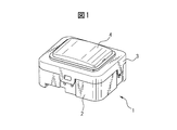
- FIG. 1 is a schematic perspective view of a push button device according to an embodiment of the present invention.
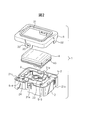
- FIG. 2 is an exploded perspective view of the push button device.
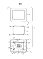
- FIG. 3 is an exploded top view of the pushbutton device.
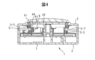
- FIG. 4 is a cross-sectional perspective view of the pushbutton device, as seen from the direction of the arrow, along the cross section indicated by AA ′ in FIG. 3.
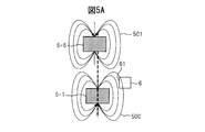
- FIG. 5A is a schematic diagram of magnetic flux lines when the button part of the push button device is not pressed.
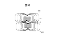
- FIG. 5B is a schematic diagram of magnetic flux lines when the button part of the push button device is pressed.
- FIG. 6 is a circuit block diagram of the detection circuit.
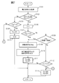
- FIG. 7 is an operation flowchart of the pressing determination and moving speed measurement processing.
- FIG. 1 is a schematic perspective view of a push button device according to an embodiment of the present invention.
- FIG. 2 is an exploded perspective view of the push button device.
- FIG. 3 is an exploded top view of the
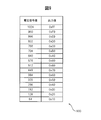
- FIG. 8 is a diagram illustrating an example of a time rate conversion table.
- FIG. 9 is a diagram illustrating an example of the voltage speed conversion table.
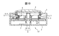
- FIG. 10 is a side cross-sectional view of a pushbutton device according to a modification, in which the cross section indicated by AA ′ in FIG. 3 is viewed from the direction of the arrow.
- FIG. 11 is a side cross-sectional view of a push button device according to another modification, in which the cross section indicated by AA ′ in FIG. 3 is viewed from the direction of the arrow.
- FIG. 12 is a schematic perspective view of a gaming machine provided with a push button device according to an embodiment or a modification of the present invention.
- FIG. 13 is a circuit block diagram of a control circuit of the gaming machine.
- This push button device uses repulsion due to the magnetic force between a plurality of magnets in order to make the user who presses the button unit supported so as to be movable in a predetermined direction feel elasticity.
- a plurality of sets of magnets provided on the case base supporting the button part and magnets provided on the button part so as to face the magnet are arranged so as to surround the center of the button part.
- each magnet provided in the button part is arranged away from the center of the button part by a predetermined distance along a line on the radiation connecting the center of the button part and the corresponding magnet provided in the case base. Is done.
- magnetic force components parallel to the plane perpendicular to the direction in which the button portion moves straightly generated by each set of magnets cancel each other, and the posture of the button portion is stabilized.
- the direction in which the button part can move is defined as the vertical direction.
- the direction in which the button part actually moves is appropriately determined according to the arrangement of the push button device.
- FIG. 1 is a schematic perspective view of a pushbutton device 1 according to the first embodiment of the present invention
- FIG. 2 is an exploded perspective view of the pushbutton device 1.
- FIG. 3 is an exploded top view of the push button device 1.
- FIG. 4 is a cross-sectional perspective view of the pushbutton device, as seen from the direction of the arrow, along the cross section indicated by AA ′ in FIG.
- the push button device 1 includes a case base 2, a case cover 3, a button portion 4, four magnets 5-1 to 5-4 attached to the case base 2, and four pieces attached to the button portion 4. Magnets 5-5 to 5-8, a magnetic sensor 6, and a detection circuit 7.
- the case base 2 and the case cover 3 constitute a support part that supports the button part 4 so as to be movable along the vertical direction.
- the case base 2 includes a side wall 21 formed in a substantially rectangular cylindrical shape along the vertical direction, and a bottom plate 22 disposed in the side wall 21 so as to be substantially orthogonal to the side wall 21.
- a latch 21 a for fixing the case cover 3 to the case base 2 and a concave portion 21 b recessed inward.
- a cylindrical projection 23 facing upward is formed at the approximate center of the bottom plate 22. And the front-end
- a rectangular protrusion 24 is formed on the upper surface of the bottom plate 22 of the case base 2 so as to surround the protrusion 23. Magnets 5-1 to 5-4 are arranged at the apexes of the protrusion 24.
- the case cover 3 is disposed above the case base 2 and constitutes a support part together with the case base 2.
- a substantially rectangular opening 31 is formed at the center of the upper surface of the case cover 3, and the upper portion of the button portion 4 is inserted into the opening 31. Therefore, the size and shape of the opening 31 are substantially equal to the size and outer shape of the upper portion of the button portion 4.
- the outer periphery size of the case cover 3 is substantially equal to the outer periphery size of the case base 2.
- Four protrusions 32 are formed along the vertical direction at the lower part of the outer periphery of the case cover 3 (note that only two of the four protrusions 32 are shown in FIGS. 1 and 2).
- Two of the four protrusions 32 are formed with holes 33 for engaging with the latches 21 a formed on the side wall 21 of the case base 2.
- the hole 33 engages with the latch 21 a and the other two of the protrusions 32 engage with the recess 21 b of the side wall 21 of the case base 2, thereby fixing the case cover 3 to the case base 2.
- a space is formed between the case cover 3 and the upper surface of the bottom plate 22 of the case base 2 so that the button portion 4 can move along the vertical direction.
- the case base 2 and the case cover 3 are formed, for example, by injection molding of resin.
- the button unit 4 is a member that moves in the vertical direction when pressed by the user, and the push button device 1 is pressed by moving downward by a predetermined distance from a state in which the button unit 4 is not pressed.
- a signal representing is output.
- the button part 4 has a substantially rectangular parallelepiped button upper part 41 and a substantially cylindrical button lower part 42 formed downward from the substantially center of the bottom surface of the button upper part 41.
- the outer shape and size of the side surface of the button upper portion 41 are substantially equal to the shape and size of the opening 31 of the case cover 3, and the button upper portion 41 is inserted into the opening 31 from the bottom surface side of the case cover 3. Therefore, the player can directly press the upper surface of the button upper portion 41.
- a fringe 43 is formed at the lower outer periphery of the button upper portion 41.
- the outer periphery size of the fringe 43 is larger than the size of the opening 31, and the button portion 4 is positioned at the upper end of the movable range. Sometimes the upper surface of the fringe 43 comes into contact with the bottom surface of the outer periphery of the opening 31 of the case cover 3. Therefore, the button part 4 is prevented from dropping through the opening 31.
- the upper surface of the button upper portion 41 may be formed with a gently curved surface that is convex upward so that the user can easily understand that the button is a button.
- the button upper part 41 may be formed in a hollow shape.
- the member that forms the upper surface of the button upper portion 41 may be formed of a transparent or translucent resin.
- a light emitting element such as a light emitting diode may be arranged inside the button upper portion 41, and the light emission intensity of the light emitting element may be adjusted by the moving speed of the button unit 4.
- the outer shape and size of the button lower portion 42 are substantially the same as the shape and size of the inner side of the protrusion 23 of the case base 2, and the button lower portion 42 is inserted into the protrusion 23. Therefore, the direction in which the button portion 4 can move is limited to the vertical direction by the protrusion 23 of the case base 2 and the opening 31 of the case cover 3.
- a quadrangular protrusion 44 is formed downward along the outer periphery of the button upper portion 41.
- the protrusion 44 is similar to the rectangular protrusion 24 formed on the case base 2 and has a horizontal cross-sectional shape that surrounds the protrusion 24. Therefore, the magnets 5-1 to 5-4 are opposed to the protrusion 44.
- each part which comprises the button part 4 is also formed by injection-molding resin, for example.
- Magnets 5-5 to 5-8 are arranged at the apexes of the protrusions 44. Thereby, the magnets 5-1 to 5-8 are arranged so as to surround the center C of the button part 4 in the horizontal plane. The center C is located on the central axis of the button part 4 along the vertical direction.
- the magnets 5-5 to 5-8 are indicated by dotted lines on the case base 2. Showed the position. As is apparent from FIG. 3, the magnets 5-5 to 5-8 are also located on a straight line extending radially from the center C on the central axis so as to pass through the magnets 5-1 to 5-4, and The magnets 5-5 to 5-8 are separated from the center C by a predetermined distance from the magnets 5-1 to 5-4.
- the predetermined distance is set to a distance, for example, 1 mm to 5 mm, that is far enough to urge the button portion 4 upward due to repulsion between the magnetic forces of the two corresponding magnets.
- the magnets 5-1 to 5-4 have the same magnetic force, and the magnets 5-5 to 5-8 also have the same magnetic force.
- Magnets 5-1 to 5-8 may each be a permanent magnet such as a neodymium magnet, or may be an electromagnet.
- the magnetic poles on the upper end side of the magnets 5-1 to 5-4 are the same as the magnetic poles on the lower end side of the magnets 5-5 to 5-8, respectively. Therefore, the magnetic force of the magnets 5-1 to 5-4 and the magnetic force of the magnets 5-5 to 5-8 repel each other, so that the button part 4 is urged upward, that is, in a direction away from the case base 2. As a result, if the button unit 4 is not pressed, the button unit 4 is positioned at the upper end of the movable range. Also, when the button unit 4 is pressed, the user can feel the elasticity corresponding to the magnetic force. Thereby, the pushbutton device 1 can provide the user with a feeling of pressing the button. When the user removes his / her finger from the button unit 4, the button unit 4 is moved upward by this magnetic force until reaching the upper end of the movable range.
- the magnets 5-1, 5-3 and the magnets 5-5, 5-7 are located on one line passing through the center C, respectively. Therefore, the horizontal component of the force acting on the button unit 4 due to the interaction between the magnetic force of the magnet 5-1 and the magnetic force of the magnet 5-5, and the interaction between the magnetic force of the magnet 5-3 and the magnetic force of the magnet 5-7. The horizontal component of the force acting on the button unit 4 is opposite to each other and cancels out.
- the magnets 5-2 and 5-4 and the magnets 5-6 and 5-8 are located on another line passing through the center C, respectively.
- the horizontal direction component of the force acting on the button portion 4 due to the interaction between the magnetic force of the magnet 5-2 and the magnetic force of the magnet 5-6, and the interaction between the magnetic force of the magnet 5-4 and the magnetic force of the magnet 5-8.
- the horizontal component of the force acting on 4 is opposite to each other and cancels out.
- the button part 4 since the horizontal component of the force applied to the button part 4 by each magnet is balanced, the button part 4 is prevented from shifting in the horizontal direction when the button part 4 is pressed.
- the repulsive force along the vertical direction at each corner of the button part 4 is substantially equal, the button part 4 is also prevented from tilting.
- the push button device 10 can improve the touch feeling of the button to the user.
- the magnetic sensor 6 has, for example, a Hall element, is generated by a magnet attached to the case base 2 and a magnet attached to the button portion 4, and changes depending on the distance between the two magnets.
- the magnetic flux density penetrating the surface 61 is detected. Therefore, it is preferable that the magnetic sensor 6 is arranged so that the angle at which the magnetic flux emitted from one magnet enters the magnetic sensing surface 61 becomes closer to the vertical as the distance between the two magnets becomes shorter. Further, the magnetic sensor 6 is preferably arranged so that the magnetic flux density coming out of the other magnet and entering the magnetic sensitive surface 61 becomes higher as the distance between the two magnets becomes shorter.
- the magnetic sensor 6 is closer to the center C side than the magnet 5-1 and closer to the side surface of the magnet 5-1 so that the button portion 4 and the magnetic sensor 6 do not come into contact when the button portion 4 is pressed.
- the magnetic sensitive surface 61 of the magnetic sensor 6 is oriented so as to be substantially parallel to the vertical direction and to face the magnet 5-1 and the magnet 5-5. Further, the upper end of the magnet 5-1 is positioned below the upper end of the magnetic sensitive surface 61, that is, the upper end of the magnetic sensitive surface 61 is closer to the magnet 5-1 when the button part 4 is not pressed.
- the magnetic sensor 6 is installed so as to be closer to the button part 4 than the upper end. Thereby, the magnetic sensor 6 can detect with high sensitivity the change in the magnetic flux density that exits from the magnet 5-1 and the magnet 5-5 and passes through the magnetic sensitive surface 61 due to the button unit 4 moving in the vertical direction.
- the upper end of the magnetically sensitive surface 61 is positioned above the lower surface of the magnet 5-5 when the button unit 4 is positioned at the lower end of the movable range, while the button unit 4 is within the movable range. More preferably, the magnetic sensor 6 is arranged such that the upper end of the magnetically sensitive surface 61 is positioned below the lower surface of the magnet 5-5 when positioned at the upper end of the magnet 5-5.
- transmits the magnetic sensitive surface 61, when the button part 4 is located in the upper end of a movable range, and the magnetic flux density which permeate
- the magnetic sensor 6 may be arranged close to any of the magnets 5-2 to 5-4 instead of the magnet 5-1. Also in this case, the positional relationship between the magnetic sensitive surface 61 of the magnetic sensor 6 and the magnets 5-2 to 5-4 and the magnets 5-6 to 5-8 is based on the magnetic sensitive surface 61 and the magnet 5- in the above-described embodiment. 1 and the magnet 5-5 are preferably arranged to be the same.
- FIG. 5A is a schematic diagram of magnetic flux lines when the button unit 4 of the pushbutton device is not pressed
- FIG. 5B is a schematic diagram of magnetic flux lines when the button unit 4 is pressed.
- lines 500 and 501 represent magnetic flux lines emanating from magnet 5-1 and magnet 5-5, respectively.
- the magnet 5-1 and the magnet 5-5 are separated from each other.
- the magnetic flux line 500 is obliquely incident on the magnetic sensitive surface 61 of the magnetic sensor 6 located in the vicinity of the upper surface of the magnet 5-1. Further, since the magnet 5-5 and the magnetic sensor 6 are separated from each other, there are few magnetic flux lines reaching the magnetic sensitive surface 61 among the magnetic flux lines 501 emitted from the magnet 5-5. Therefore, the magnetic flux density detected by the magnetic sensor 6 is relatively low.
- the magnetic flux line 500 coming out from the upper surface of the magnet 5-1 becomes the magnet 5-5.
- the magnetic flux lines 500 are curved downward on the lower side than when the gap between the magnets 5-1 and 5-5 is wide. As a result, the number of magnetic flux lines incident substantially perpendicular to the magnetically sensitive surface 61 increases, so that the magnetic flux line density on the magnetically sensitive surface 61 also increases.
- the gap between the magnet 5-5 and the magnetic sensitive surface 61 is narrowed, the density of the magnetic flux lines 501 that pass through the magnetic sensitive surface 61 and exit from the lower surface of the magnet 5-5 also increases. Therefore, the magnetic flux density detected by the magnetic sensor 6 is relatively high.
- the button unit 4 when the button unit 4 is moved along the vertical direction when the button unit 4 is pressed, the distance between the magnet 5-1 and the magnet 5-5 is shortened along with the movement, so that the magnetic sensor The magnetic flux density detected by 6 also changes. Therefore, the change in the magnetic flux density detected by the magnetic sensor 6 represents the amount of movement of the button unit 4.
- the magnetic sensor 6 outputs a voltage corresponding to the detected magnetic flux density to the detection circuit 7.
- the detection circuit 7 determines whether or not the button unit 4 has been pressed based on the voltage output from the magnetic sensor 6 and determines the moving speed of the button unit 4.
- the detection circuit 7 is disposed on a substrate (not shown) disposed in the space between the case base 2 and the case cover 3 and is connected to the magnetic sensor 6 via a signal line.
- the detection circuit 7 may be disposed on a substrate provided outside the case base 2 and the case cover 3.
- the detection circuit 7 is connected to a main control circuit (not shown) of a gaming machine on which the push button device 1 is mounted via a signal line, and the button unit 4 is pressed to the main control circuit, and A signal representing the moving speed of the button unit 4 is output.
- FIG. 6 is a circuit block diagram of the detection circuit 7.
- the detection circuit 7 includes an analog / digital converter 71, a memory 72, and an arithmetic circuit 73.
- the analog / digital converter 71, the memory 72, and the arithmetic circuit 73 may be separate circuits or may be integrally formed as one integrated circuit.
- the analog / digital converter 71 converts the output voltage from the magnetic sensor 6 into a voltage signal that is a digital signal corresponding to the output voltage, and outputs the voltage signal to the arithmetic circuit 73.
- the output voltage from the magnetic sensor 6 may be amplified by an amplifier, and the amplified output voltage may be input to the analog / digital converter 71.
- the memory 72 includes, for example, a nonvolatile non-writable semiconductor memory and a volatile read / write semiconductor memory.
- the memory 72 stores data used for determining whether or not the button unit 4 has been pressed, and data used for detecting the moving speed of the button unit 4.
- the memory 72 has a voltage threshold value used for determining whether or not the button unit 4 has been pressed, and a counter value representing the time required for the button unit 4 to move between two preset points. And a time speed conversion table showing the relationship between the movement speed of the button unit 4 and the like.
- the arithmetic circuit 73 is configured by a dedicated arithmetic circuit configured as a general-purpose processor or ASIC, for example. Then, the arithmetic circuit 73 determines whether or not the button unit 4 is pressed based on the voltage signal corresponding to the output voltage from the magnetic sensor 6 received from the analog / digital converter 71, and Find the moving speed.
- FIG. 7 is an operation flowchart of the pressing determination and movement speed measurement processing executed by the arithmetic circuit 73.
- the arithmetic circuit 73 executes the pressing determination and the movement speed measurement process according to the following operation flowchart at regular intervals. Note that the fixed period is set to a time shorter than the time required for the user to press the button once, for example, 20 ⁇ sec.
- the arithmetic circuit 73 When the power of the pushbutton device 1 is turned on, the arithmetic circuit 73, as an initial setting, displays a push-down flag Fb indicating whether or not the push-down pressure is applied to the button unit 4, and the push-down pressure is Set it off to indicate that it is not hung. In addition, the arithmetic circuit 73 returns to the state where the pressed pressure is not applied to the pressed flag Fa indicating whether or not the pressing force is not applied to the button unit 4 after the push button device 1 is pressed once. Set to off to indicate that. Further, the arithmetic circuit 73 sets the value of the counter C that represents the number of times that the voltage signal value is acquired after the pressing force is applied to the button unit 4 to 0.
- the arithmetic circuit 73 acquires the voltage signal V corresponding to the output voltage from the magnetic sensor 6 from the analog / digital converter (step S101). Then, the arithmetic circuit 73 determines whether or not the pressing flag Fb is ON indicating that the pressing force is applied to the button unit 4 and the pressed flag Fa is OFF (step S102). . If the pressed flag Fb is off, or if the pressed flag Fa is turned on indicating that the button unit 4 has not returned to the state where the pressing pressure is not applied (No in step S102), the calculation is performed. The circuit 73 determines whether or not the voltage signal V is greater than or equal to the measurement start threshold Th1 (step S103).
- the measurement start threshold Th1 is set to a voltage signal value when the button unit 4 is located a predetermined distance (for example, 1 mm to 2 mm) below the upper end of the movable range. If the voltage signal V is equal to or greater than the measurement start threshold Th1 (step S103-Yes), it is determined that the pressing force is applied to the button unit 4. Therefore, the arithmetic circuit 73 sets the pressing flag Fb to on (step S104). The arithmetic circuit 73 resets the value of the counter C to 0 (step S105). Note that the processing order of steps S104 and S105 may be switched. Thereafter, the arithmetic circuit 73 waits for acquisition of the next voltage signal V.
- a predetermined distance for example, 1 mm to 2 mm
- step S103-No if the voltage signal V is less than the measurement start threshold value Th1 (step S103-No), it is determined that the pressing force is not applied to the button unit 4 and the initial state is restored. Therefore, the arithmetic circuit 73 sets the pressed flag Fa and the pressed flag Fb to off (step S113). Thereafter, the arithmetic circuit 73 waits for acquisition of the next voltage signal V.
- step S102 when the pressed flag Fb is on and the pressed flag Fa is off (step S102-Yes), the arithmetic circuit 73 increments the value of the counter C by 1 (step S106). Then, the arithmetic circuit 73 determines whether or not the voltage signal V is equal to or greater than the pressing detection threshold Th2 (step S107).
- the press detection threshold Th2 is set to a voltage signal value corresponding to a position where it is determined that the button unit 4 is pressed. Therefore, the pressing detection threshold Th2 is larger than the detection start threshold Th1. That is, the position of the button unit 4 corresponding to the pressing detection threshold Th2 is lower than the position of the button unit 4 corresponding to the detection start threshold Th1.
- step S107-No If the voltage signal V is less than the pressing detection threshold value Th2 (step S107-No), it does not move downward enough to determine that the button unit 4 has been pressed. In this case, the arithmetic circuit 73 determines whether or not the value of the counter C has reached an upper limit value (for example, 1000) (step S108). If the value of the counter C has reached the upper limit (step S108—Yes), or if the voltage signal V is equal to or greater than the press detection threshold Th2 in step S107 (step S107—Yes), the arithmetic circuit 73 It is determined that the button unit 4 has been pressed. Then, the arithmetic circuit 73 obtains the moving speed of the button unit 4 based on the counter C or the voltage signal V (step S109).
- an upper limit value for example, 1000
- the button unit 4 starts from a position corresponding to the detection start threshold Th1 within a period obtained by multiplying the value of the counter C by the voltage signal acquisition cycle. It is estimated that the robot has moved to a position corresponding to the press detection threshold Th2. Therefore, the arithmetic circuit 73 determines the distance between the magnet 5-1 and the magnet 5-5 at the position corresponding to the press detection threshold Th2 from the distance between the magnet 5-1 and the magnet 5-5 at the position corresponding to the detection start threshold Th1. Is divided by a period (C ⁇ P) obtained by multiplying the value of the counter C by the voltage signal acquisition period P, the moving speed of the button unit 4 can be calculated. Note that the difference ⁇ and the voltage signal acquisition cycle P are known values, and are stored in advance in the memory 72, for example.
- a time speed conversion table representing the relationship between the value of the counter C and the moving speed may be stored in the memory 72 in advance.
- the arithmetic circuit 73 can obtain the moving speed of the button unit 4 by referring to the time speed conversion table and specifying the moving speed corresponding to the value of the counter C.
- FIG. 8 is a diagram showing an example of a time rate conversion table.
- Each column of the left column of the time speed conversion table 800 shown in FIG. 8 stores the reference value of the counter C, while each column of the right column represents the moving speed corresponding to the reference value.
- the output value is stored.
- the output value is expressed in hexadecimal.For example, the value '0x10' stored in the bottom column corresponds to 0.5mm / sec, and the value '0xFF' stored in the top column is 50mm / sec. Corresponds to sec.
- the arithmetic circuit 73 compares the value of the counter C when the voltage signal V becomes equal to or greater than the pressing detection threshold Th2 with the reference value stored in the column in order from the upper column of the time speed conversion table 800. Then, when the value of the counter C becomes equal to or less than the reference value, the arithmetic circuit 73 specifies the value of the moving speed stored in the same row as the reference value as the moving speed of the button unit 4.
- the relationship between the voltage signal V and the position of the button unit 4 is known because it can be measured in advance through experiments, for example. Further, when the value of the counter C reaches the upper limit, the elapsed time after the button unit 4 is pressed down to the position corresponding to the detection start threshold Th1 is obtained by multiplying the voltage signal acquisition cycle P by the upper limit Climit. It has become. Accordingly, the arithmetic circuit 73 determines the distance between the magnet 5-1 and the magnet 5-5 at the position corresponding to the detection start threshold Th1 and the voltage signal V based on the voltage signal V when the value of the counter C reaches the upper limit.
- the moving speed of the button unit 4 can be obtained by calculating the distance difference d between the magnet 5-1 and the magnet 5-5 at the position corresponding to, and dividing the difference d by the elapsed time (Climit ⁇ P). it can. Note that a movement amount conversion table representing the relationship between the voltage signal V and the difference d is stored in the memory 72 in advance.
- a voltage speed conversion table representing the correspondence between the voltage signal V and the moving speed of the button unit 4 may be stored in the memory 72 instead of the movement amount conversion table.
- the arithmetic circuit 73 can specify the moving speed corresponding to the voltage signal V with reference to the voltage speed conversion table.
- FIG. 9 is a diagram showing an example of the voltage speed conversion table.
- the reference value of the voltage signal V digitized by the analog / digital converter 71 is stored, while in each column of the right column.
- the output value is expressed in hexadecimal.For example, the value '0x10' stored in the bottom column corresponds to 0.5mm / sec, and the value '0xFF' stored in the top column is 50mm / sec. Corresponds to sec.
- the arithmetic circuit 73 compares the value of the voltage signal V when the value of the counter C reaches the upper limit value Climit sequentially from the upper column of the voltage speed conversion table 800 with the reference value stored in that column. Then, when the value of the voltage signal V becomes equal to or lower than the reference value, the arithmetic circuit 73 specifies the value of the moving speed stored in the same row as the reference value as the moving speed of the button unit 4.
- the main control circuit of the gaming machine uses a pressing detection signal indicating that the button unit 4 has been pressed and a speed signal indicating the moving speed. (Not shown) is output (step S110).
- the arithmetic circuit 73 sets the pressed flag Fa to on and sets the pressed flag Fb to off so that the pressing detection signal is not output a plurality of times by one pressing (step S111). Thereafter, the arithmetic circuit 73 waits for acquisition of the next voltage signal V.
- step S108-No the arithmetic circuit 73 determines whether or not the voltage signal V is less than the detection start threshold Th1 (step S108). S112). If the voltage signal V is less than the detection start threshold Th1 (step S112—Yes), the button unit 4 has returned to a position where no pressure is applied, and before the button unit 4 is detected to be pressed. It is estimated that the user has lifted his / her finger from the button unit 4. Therefore, the arithmetic circuit 73 sets the pressed flag Fa and the pressed flag Fb to off (step S113). After step S113 or when the voltage signal V is equal to or greater than the detection start threshold Th1 in step S112 (step S112—No), the arithmetic circuit 73 waits for acquisition of the next voltage signal V.
- this push button device is provided with a plurality of sets of magnets attached to the case base side and magnets attached to the button portion side.
- the magnet is enclosed and arranged so that the button side magnet is positioned outside the corresponding case base side magnet.
- this push button device can output the moving speed as useful information representing the user's operation to a device intended for control according to the operation of the user pressing the button unit.
- this push button device uses the magnetic flux density when the button portion is located at the upper end of the movable range and the magnetic flux density when the button portion is located at the lower end of the movable range in order to obtain the moving speed of the button portion. It is only necessary that the magnetic sensor can detect the difference between. Therefore, since this push button device can shorten the movable range of the button part, the vertical size of the entire push button device can be reduced.
- this push button device can detect the position change of the button part sensitively by arranging the magnetic sensor at the position where the magnetic flux lines coming out of each of the two magnets are affected by the distance between the magnets.
- the movable range of the button part can be shortened.
- this push button device uses only one magnetic sensor to detect the moving speed of the button part and the pressing of the button part, the space for arranging the sensor can be reduced. Therefore, the push button device can be downsized as a whole.
- the plurality of magnets attached to the button part side are arranged to be closer to the center C by a predetermined distance (for example, 1 mm to 5 mm) than the corresponding magnets attached to the case base part side. May be.
- the number of magnets attached to the button part side and the number of magnets attached to the case base part side are not limited to four.
- the push button device has three or more sets of magnets attached to the button base side and corresponding magnets attached to the case base side, so that the horizontal components of the force applied to the button part by each magnet set cancel each other. In addition, it is only necessary to arrange each magnet set.
- the pushbutton device may have three sets of magnets, and each set of magnets may be arranged at each vertex of an equilateral triangle having the center C as the center of gravity. Also in this case, the magnets attached to the button part side are separated from the center C by a predetermined distance along the radial line passing through the center C with the corresponding magnets attached to the case base side, or by a predetermined distance. It arrange
- the push button device may have a sensor for detecting that the lower part of the button has been pushed down to the detection start position, separately from the magnetic sensor.
- FIG. 10 is a side cross-sectional view of the push button device according to this modification, in which the cross section indicated by AA ′ in FIG. 3 is viewed from the direction of the arrow.
- a push button device 10 according to this modification includes a case base 2, a case cover 3, a button 4, a set of four magnets, a magnetic sensor 6, a detection circuit 7, and an optical sensor 8.
- FIG. 10 only two of the four magnet sets, ie, magnets 5-1 and 5-5 and magnets 5-3 and 5-7 are shown.
- the push button device 10 is different from the push button device 1 described above in that it has an optical sensor 8. Therefore, hereinafter, the optical sensor 8 and related portions will be described.
- the optical sensor 8 includes a light emitting element 81 such as a light emitting diode and a light receiving element 82 such as a photodiode. While the power is being supplied to the push button device 10, the light emitting element 81 is lit and the light receiving element 82 outputs a signal corresponding to the detected light intensity to the detection circuit 7.
- the light emitting element 81 and the light receiving element 82 are mutually within the protrusion 24 of the case base 2 below a predetermined distance (for example, 1 mm to 2 mm) below the lower end of the button lower part 42 when the button part 4 is not pressed. It arrange
- the detection circuit 7 does not compare the voltage signal from the magnetic sensor 6 with the threshold value Th1, instead of the light receiving element.
- the detection circuit 7 is configured such that when the intensity of the signal received from the light receiving element 82 is less than the luminance threshold corresponding to the intensity of the signal when the light receiving element 82 detects light from the light emitting element 81. It can be determined that the pressing force is applied to the button unit 4.
- the intensity of the signal received from the light receiving element 82 is equal to or higher than the luminance threshold value, it can be determined that the pressing force is not applied to the button unit 4.
- the magnetic sensor may be fixed to the button part.
- the magnetic sensor has a magnetic sensing surface that is substantially perpendicular to the vertical direction so that the magnetic flux density can be detected according to the distance between the magnet attached to the button portion and the magnet attached to the case base. They are arranged in parallel so as to face the magnet attached to the button part and the magnet attached to the case base. Furthermore, in the magnetic sensor, as the distance between the magnet attached to the button portion and the magnet attached to the case base portion becomes shorter, the angle at which the magnetic flux emitted from the magnet attached to the button portion enters the magnetic sensitive surface becomes vertical.
- the magnetic flux is arranged so that the density of the magnetic flux coming out of the magnet attached to the case base and entering the magnetically sensitive surface becomes high.
- the magnetic sensor is preferably arranged so that the lower end of the magnetically sensitive surface is located below the lower end of the button portion.
- the push button device may determine whether or not the button unit is pressed using an optical sensor. Furthermore, the push button device may not detect the moving speed of the button.
- FIG. 11 is a side cross-sectional view of the pushbutton device according to this modification, in which the cross section indicated by AA ′ in FIG. 3 is viewed from the direction of the arrow.
- the push button device 20 according to this modification includes a case base 2, a case cover 3, a button 4, a set of four magnets, a detection circuit 7, and an optical sensor 8.
- FIG. 11 only two of the four magnet sets, ie, magnets 5-1 and 5-5 and magnets 5-3 and 5-7 are shown.
- the push button device 20 does not have the magnetic sensor 6 as compared with the push button device 10 shown in FIG. 10, and instead, the optical sensor 8 is used to determine whether or not the button portion is pressed. The point is different. Therefore, the optical sensor 8 will be described below.
- the optical sensor 8 includes a light emitting element 81 such as a light emitting diode and a light receiving element 82 such as a photodiode. While the power is being supplied to the push button device 10, the light emitting element 81 is lit and the light receiving element 82 outputs a signal corresponding to the detected light intensity to the detection circuit 7.
- the light emitting element 81 and the light receiving element 82 are projected from the lower end of the button lower part 42 when the button part 4 is positioned at the lower end of the movable range by a predetermined distance (for example, 1 mm to 2 mm). 24 are arranged so as to face each other.
- the optical sensor 8 moves to the vicinity of the lower end of the movable range when the button unit 4 is pressed, the light receiving element 82 of the optical sensor 8 outputs a lower signal value than when the button unit 4 is not pressed. .
- the detection circuit 7 can determine that the button unit 4 has been pressed when the intensity of the signal received from the light receiving element 82 is less than the luminance threshold value, while the intensity of the signal received from the light receiving element 82 is the luminance threshold value. If it is above, it can determine with the button part 4 not being pressed down.
- the magnets 5-5 to 5-8 are arranged closer to the center of the button part 4 by a predetermined distance than the magnets 5-1 to 5-4. Even when the magnets are arranged in this way, the horizontal components of the repulsive force generated by each magnet pair (magnet 5-1 and magnet 5-5, magnet 5-3 and magnet 5-7, etc.) cancel each other, so the button portion The posture when 4 is pressed is also kept stable.
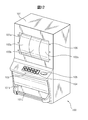
- FIG. 12 is a schematic perspective view of a gaming machine 100 including a push button device according to an embodiment or a modification of the present invention.
- the gaming machine 100 includes a main body casing 101 that is a gaming machine main body, three reels 102a to 102c, a plurality of operation buttons 103, a start button 104, and a selection button 105. Furthermore, the gaming machine 100 has a control circuit 110 inside the main body housing 101.
- FIG. 13 is a circuit block diagram of the control circuit 110.
- the control circuit 110 includes a main control circuit 111 that controls the entire gaming machine 100, an effect control circuit 112 that controls each part related to the effect of the game, and power to each part of the gaming machine 100. And a power supply circuit 113 for supplying power.
- An opening 101a is formed in the upper center of the front surface of the main body casing 101, and the reels 102a to 102c are visible through the opening 101a.
- the lower side of the opening 101a is formed so as to protrude to the front side, and the upper surface of the protruding portion is formed in a table shape.
- a plurality of operation buttons 103, a start button 104, and a selection button 105 are arranged in order from the left toward the front of the gaming machine 100.
- Each operation button 103, start button 104, and selection button 105 are configured by a push button device according to any of the above-described embodiments or modifications thereof.
- a medal discharge port 101b for discharging medals is formed in the lower part of the front surface of the main body casing 101.
- a medal tray 101c for preventing the discharged medals from falling is attached below the medal discharge port 101b.
- a speaker (not shown) may be attached near the upper left end and near the upper right end of the main body casing 101.
- a plurality of decorative light emitting diodes 106 may be attached around the opening 101 a of the main body casing 101 and around each operation button 103 or inside the button portion of each operation button 103.
- the reels 102a to 102c are an example of a movable portion, and in accordance with a control signal from the production control circuit 112, a rotation axis (not shown) that is substantially parallel and substantially horizontal to the front surface of the main body casing 101 is the center of rotation. Each can be rotated separately.
- the surface of each of the reels 102a to 102c is divided into a plurality of regions having substantially the same width along the rotation direction, and various designs are drawn for each region.
- a display device such as a liquid crystal display may be provided so that the display screen can be seen through the opening 101a. In this case, the display device displays an image showing a plurality of drums on the display screen in response to the control signal from the effect control circuit 112.
- the medal identification device detects the medal every time a medal is inserted and detects that the medal has been detected. Notify the main control circuit 111. Then, the main control circuit 111 determines the number of games according to the number of inserted medals, and permits the gaming machine 100 to start the game.
- the main control circuit 111 operates the operation among a plurality of lines connecting a plurality of symbols across three reels.
- the line associated with the button is selected as a winning line that is won when the same symbol is lined up along the line.
- the main control circuit 111 changes the bet number according to the number of times the button is pressed.
- the pressed operation button 103 notifies the main control circuit 111 of the moving speed of the button portion of the operation button 103.
- the main control circuit 111 outputs a signal representing the moving speed or a control signal corresponding to the speed to the effect control circuit 112.
- the production control circuit 112 changes the light emission intensity or light emission color of the light emitting diodes disposed in or around the operation button 103 in accordance with a signal representing the speed or a control signal. For example, as the moving speed of the button portion of the pressed operation button increases, the effect control circuit 112 increases the light emission intensity of the light emitting diodes arranged in or around the operation button.
- the production control circuit 112 operates the light emission intensity of the light emitting diodes located at both ends of the winning line corresponding to the pressed operation button 103 among the plurality of light emitting diodes arranged around the opening 101a. You may enlarge, so that the moving speed of the button part of a button is high. Further, the main control circuit 111 may display a message warning a failure on a display (not shown) when the moving speed exceeds a predetermined threshold.
- the main control circuit 111 causes the effect control circuit 112 to start rotating the reels 102a to 102c. Further, the effect control circuit 112 increases the rotation speed of the reels 102a to 102c as the moving speed of the pressed button portion of the start button 104 increases.
- the main control circuit 111 receives a signal indicating that the button has been pressed and a signal indicating the moving speed of the button portion of the selection button 105, and transmits a predetermined time. After the elapse of time, the rotation of the reels 102a to 102c is stopped via the effect control circuit 112. At this time, the main control circuit 111 shortens the time until the reels 102a to 102c are stopped as the moving speed of the button portion of the selection button 105 increases.
- the main control circuit 111 selects a predetermined number of medals according to the symbol as medals. Discharge through the outlet. Also, in this case, the effect control circuit 111 may output a sound effect through the speaker that is different from the sound effect when the same symbol is not lined up along all the reels during rotation of the reel and along the winning line. Good.
Landscapes
- Physics & Mathematics (AREA)
- General Physics & Mathematics (AREA)
- Push-Button Switches (AREA)
- Slot Machines And Peripheral Devices (AREA)
- Switches That Are Operated By Magnetic Or Electric Fields (AREA)
Abstract
La présente invention concerne un dispositif bouton-poussoir (1, 10, 20) qui comporte : une section bouton (4) qui peut être déplacée le long d'une direction prédéterminée ; une section support (2, 3) pour supporter la section bouton (4) ; de multiples premiers aimants (5-1 à 5-4) qui sont fixés à la section support (2, 3), fixée afin d'entourer le centre de la section bouton (4), et comportent des premiers pôles magnétiques sur les côtés respectifs qui font face à la section bouton (4) ; de multiples seconds aimants (5-5 à 5-8) qui sont agencés dans des positions éloignées du centre de la section bouton (4) à une distance prédéterminée des premiers aimants respectifs, ou dans des positions plus près du centre de la section bouton (4) à une distance prédéterminée des premiers aimants respectifs, et possèdent des premiers pôles magnétiques sur les côtés respectifs qui font face aux premiers aimants ; et un capteur (6, 8) pour détecter un appui sur la section bouton (4) selon une quantité prédéterminée.
Priority Applications (2)
| Application Number | Priority Date | Filing Date | Title |
|---|---|---|---|
| US14/371,645 US20140364235A1 (en) | 2012-02-03 | 2012-11-21 | Pushbutton device and game machine |
| EP12867582.4A EP2811503A4 (fr) | 2012-02-03 | 2012-11-21 | Dispositif bouton-poussoir et machine de jeu |
Applications Claiming Priority (2)
| Application Number | Priority Date | Filing Date | Title |
|---|---|---|---|
| JP2012021818A JP2013161612A (ja) | 2012-02-03 | 2012-02-03 | 押ボタン装置及び遊技機 |
| JP2012-021818 | 2012-02-03 |
Publications (1)
| Publication Number | Publication Date |
|---|---|
| WO2013114709A1 true WO2013114709A1 (fr) | 2013-08-08 |
Family
ID=48904771
Family Applications (1)
| Application Number | Title | Priority Date | Filing Date |
|---|---|---|---|
| PCT/JP2012/080194 Ceased WO2013114709A1 (fr) | 2012-02-03 | 2012-11-21 | Dispositif bouton-poussoir et machine de jeu |
Country Status (4)
| Country | Link |
|---|---|
| US (1) | US20140364235A1 (fr) |
| EP (1) | EP2811503A4 (fr) |
| JP (1) | JP2013161612A (fr) |
| WO (1) | WO2013114709A1 (fr) |
Cited By (1)
| Publication number | Priority date | Publication date | Assignee | Title |
|---|---|---|---|---|
| US11699560B2 (en) | 2021-05-07 | 2023-07-11 | Aristocrat Technologies, Inc. | Button deck with non-penetrating pushbutton |
Families Citing this family (12)
| Publication number | Priority date | Publication date | Assignee | Title |
|---|---|---|---|---|
| US10022622B2 (en) | 2014-04-21 | 2018-07-17 | Steelseries Aps | Programmable actuation inputs of an accessory and methods thereof |
| US10675532B2 (en) | 2014-04-21 | 2020-06-09 | Steelseries Aps | Variable actuators of an accessory and methods thereof |
| JP6394099B2 (ja) * | 2014-06-18 | 2018-09-26 | オムロン株式会社 | 操作ユニット |
| US10237710B2 (en) * | 2015-09-28 | 2019-03-19 | Eaton Intelligent Power Limited | Control system with smart devices for hazardous environments |
| JP6703348B2 (ja) * | 2016-05-13 | 2020-06-03 | 三菱電機ビルテクノサービス株式会社 | エレベータの押しボタン装置 |
| JP2020146085A (ja) * | 2019-03-11 | 2020-09-17 | サミー株式会社 | 遊技機用操作装置 |
| JP2020146086A (ja) * | 2019-03-11 | 2020-09-17 | サミー株式会社 | 遊技機用演出装置 |
| JP7293995B2 (ja) | 2019-08-29 | 2023-06-20 | オムロン株式会社 | 押しボタン装置 |
| JP7354694B2 (ja) * | 2019-08-29 | 2023-10-03 | オムロン株式会社 | 押しボタン装置 |
| JP7375927B2 (ja) * | 2020-05-28 | 2023-11-08 | オムロン株式会社 | 押しボタンスイッチ、押しボタンスイッチユニット、操作ユニット、および遊技機 |
| KR102615952B1 (ko) * | 2021-10-28 | 2023-12-22 | (주)코텍 | 카지노머신용 버튼장치 |
| DE102023117235A1 (de) * | 2023-06-29 | 2025-01-02 | Leica Camera Aktiengesellschaft | Auslöser für eine kamera und kamera |
Citations (4)
| Publication number | Priority date | Publication date | Assignee | Title |
|---|---|---|---|---|
| JPS5091663U (fr) * | 1973-12-27 | 1975-08-02 | ||
| JPH024029A (ja) | 1988-06-22 | 1990-01-09 | San Dengiyoushiya:Kk | 押ボタン形リニア出力装置 |
| JPH0619781U (ja) * | 1992-03-18 | 1994-03-15 | 株式会社森木工 | ゲーム機のストップスイッチ |
| JPH097459A (ja) * | 1995-04-19 | 1997-01-10 | Idec Izumi Corp | 薄型スイッチおよびスイッチ付表示パネル |
Family Cites Families (2)
| Publication number | Priority date | Publication date | Assignee | Title |
|---|---|---|---|---|
| CN1051634C (zh) * | 1994-12-28 | 2000-04-19 | 和泉电气株式会社 | 薄型开关装置及带开关的显示装置 |
| US7385645B2 (en) * | 2004-02-02 | 2008-06-10 | Paul Boon | Magnetic repulsion actuator for underwater camera |
-
2012
- 2012-02-03 JP JP2012021818A patent/JP2013161612A/ja active Pending
- 2012-11-21 EP EP12867582.4A patent/EP2811503A4/fr not_active Withdrawn
- 2012-11-21 US US14/371,645 patent/US20140364235A1/en not_active Abandoned
- 2012-11-21 WO PCT/JP2012/080194 patent/WO2013114709A1/fr not_active Ceased
Patent Citations (4)
| Publication number | Priority date | Publication date | Assignee | Title |
|---|---|---|---|---|
| JPS5091663U (fr) * | 1973-12-27 | 1975-08-02 | ||
| JPH024029A (ja) | 1988-06-22 | 1990-01-09 | San Dengiyoushiya:Kk | 押ボタン形リニア出力装置 |
| JPH0619781U (ja) * | 1992-03-18 | 1994-03-15 | 株式会社森木工 | ゲーム機のストップスイッチ |
| JPH097459A (ja) * | 1995-04-19 | 1997-01-10 | Idec Izumi Corp | 薄型スイッチおよびスイッチ付表示パネル |
Non-Patent Citations (1)
| Title |
|---|
| See also references of EP2811503A4 |
Cited By (3)
| Publication number | Priority date | Publication date | Assignee | Title |
|---|---|---|---|---|
| US11699560B2 (en) | 2021-05-07 | 2023-07-11 | Aristocrat Technologies, Inc. | Button deck with non-penetrating pushbutton |
| US11915897B2 (en) | 2021-05-07 | 2024-02-27 | Aristocrat Technologies, Inc. | Button deck with non-penetrating pushbutton |
| US12148586B2 (en) | 2021-05-07 | 2024-11-19 | Aristocrat Technologies, Inc. | Button deck with non-penetrating pushbutton |
Also Published As
| Publication number | Publication date |
|---|---|
| US20140364235A1 (en) | 2014-12-11 |
| JP2013161612A (ja) | 2013-08-19 |
| EP2811503A4 (fr) | 2015-11-18 |
| EP2811503A1 (fr) | 2014-12-10 |
Similar Documents
| Publication | Publication Date | Title |
|---|---|---|
| WO2013114709A1 (fr) | Dispositif bouton-poussoir et machine de jeu | |
| EP3272402B1 (fr) | Dispositif de commande de jeu | |
| JP6413372B2 (ja) | 操作ユニットおよび遊技機 | |
| US20140008188A1 (en) | Switch unit and game machine | |
| JP2013161615A (ja) | 押ボタン装置及び遊技機 | |
| JP2009078182A (ja) | 遊技機 | |
| US20150277584A1 (en) | Operation unit | |
| JP2013164907A (ja) | 押ボタン装置及び遊技機 | |
| JP2016532977A (ja) | 熱感知器 | |
| JP2012514807A (ja) | 固定型マウス | |
| US11373478B2 (en) | Game machine | |
| JP2015066352A (ja) | 遊技機 | |
| JP2015066354A (ja) | 遊技機 | |
| JP5535362B1 (ja) | 複合操作スイッチ | |
| US10490019B2 (en) | Lever handle and game machine | |
| WO2010058208A1 (fr) | Machine d'amusement et ensemble bouton-poussoir | |
| JP6043908B2 (ja) | 遊技機 | |
| JP4936669B2 (ja) | 遊技機用操作スイッチ | |
| JP4810670B2 (ja) | 動き検出装置、コンピュータプログラム、及び、ゲーム機 | |
| JP2010140914A (ja) | 光電スイッチ及びそれを用いた物体の検出方法 | |
| JP2015066353A (ja) | 操作ユニット | |
| JP2006006715A (ja) | 遊技機用スイッチユニット | |
| JP6343835B2 (ja) | 遊技機 | |
| JP2004215705A (ja) | 遊技機用操作ボタン装置及びパネル部材 | |
| JP4753212B2 (ja) | 遊技機用操作ボタン装置 |
Legal Events
| Date | Code | Title | Description |
|---|---|---|---|
| 121 | Ep: the epo has been informed by wipo that ep was designated in this application |
Ref document number: 12867582 Country of ref document: EP Kind code of ref document: A1 |
|
| WWE | Wipo information: entry into national phase |
Ref document number: 14371645 Country of ref document: US |
|
| REEP | Request for entry into the european phase |
Ref document number: 2012867582 Country of ref document: EP |
|
| WWE | Wipo information: entry into national phase |
Ref document number: 2012867582 Country of ref document: EP |
|
| NENP | Non-entry into the national phase |
Ref country code: DE |