WO2013122003A1 - Ballonnet pour cathéter à ballonnet d'occlusion vasculaire, cathéter à ballonnet d'occlusion vasculaire, et procédé de production de ballonnet pour cathéter à ballonnet d'occlusion vasculaire - Google Patents
Ballonnet pour cathéter à ballonnet d'occlusion vasculaire, cathéter à ballonnet d'occlusion vasculaire, et procédé de production de ballonnet pour cathéter à ballonnet d'occlusion vasculaire Download PDFInfo
- Publication number
- WO2013122003A1 WO2013122003A1 PCT/JP2013/053066 JP2013053066W WO2013122003A1 WO 2013122003 A1 WO2013122003 A1 WO 2013122003A1 JP 2013053066 W JP2013053066 W JP 2013053066W WO 2013122003 A1 WO2013122003 A1 WO 2013122003A1
- Authority
- WO
- WIPO (PCT)
- Prior art keywords
- balloon
- rear end
- end side
- tube
- vascular occlusion
- Prior art date
- Legal status (The legal status is an assumption and is not a legal conclusion. Google has not performed a legal analysis and makes no representation as to the accuracy of the status listed.)
- Ceased
Links
Images




Classifications
-
- A—HUMAN NECESSITIES
- A61—MEDICAL OR VETERINARY SCIENCE; HYGIENE
- A61M—DEVICES FOR INTRODUCING MEDIA INTO, OR ONTO, THE BODY; DEVICES FOR TRANSDUCING BODY MEDIA OR FOR TAKING MEDIA FROM THE BODY; DEVICES FOR PRODUCING OR ENDING SLEEP OR STUPOR
- A61M25/00—Catheters; Hollow probes
- A61M25/10—Balloon catheters
- A61M25/1002—Balloon catheters characterised by balloon shape
-
- A—HUMAN NECESSITIES
- A61—MEDICAL OR VETERINARY SCIENCE; HYGIENE
- A61M—DEVICES FOR INTRODUCING MEDIA INTO, OR ONTO, THE BODY; DEVICES FOR TRANSDUCING BODY MEDIA OR FOR TAKING MEDIA FROM THE BODY; DEVICES FOR PRODUCING OR ENDING SLEEP OR STUPOR
- A61M25/00—Catheters; Hollow probes
- A61M25/10—Balloon catheters
- A61M25/1027—Making of balloon catheters
- A61M25/1029—Production methods of the balloon members, e.g. blow-moulding, extruding, deposition or by wrapping a plurality of layers of balloon material around a mandril
-
- A—HUMAN NECESSITIES
- A61—MEDICAL OR VETERINARY SCIENCE; HYGIENE
- A61M—DEVICES FOR INTRODUCING MEDIA INTO, OR ONTO, THE BODY; DEVICES FOR TRANSDUCING BODY MEDIA OR FOR TAKING MEDIA FROM THE BODY; DEVICES FOR PRODUCING OR ENDING SLEEP OR STUPOR
- A61M25/00—Catheters; Hollow probes
- A61M25/10—Balloon catheters
- A61M25/104—Balloon catheters used for angioplasty
-
- A—HUMAN NECESSITIES
- A61—MEDICAL OR VETERINARY SCIENCE; HYGIENE
- A61M—DEVICES FOR INTRODUCING MEDIA INTO, OR ONTO, THE BODY; DEVICES FOR TRANSDUCING BODY MEDIA OR FOR TAKING MEDIA FROM THE BODY; DEVICES FOR PRODUCING OR ENDING SLEEP OR STUPOR
- A61M25/00—Catheters; Hollow probes
- A61M25/10—Balloon catheters
- A61M25/1002—Balloon catheters characterised by balloon shape
- A61M2025/1004—Balloons with folds, e.g. folded or multifolded
Definitions
- the present invention relates to a balloon for a vascular occlusion balloon catheter, a method for producing the same, and a vascular occlusion balloon catheter.
- a blood vessel occlusion balloon catheter is used to temporarily occlude a blood vessel and inject a drug in order to administer a drug solution such as a chemotherapeutic agent to an affected area.
- the balloon catheter for vascular occlusion of the present invention does not have a hard and high expansion force as used in percutaneous coronary artery dilatation (PTCA), percutaneous arterial dilatation (PTA), etc., and is elastic.
- the present invention relates to a balloon catheter for vascular occlusion that can be deformed and can block blood flow without imposing excessive pressure on a blood vessel wall.
- Patent Document 1 Japanese Patent Laid-Open No.
- the balloon catheter 1 of Patent Document 1 includes a double-tube catheter main body 3 including an inner tube 9 and an outer tube 21.
- a balloon 7 is attached to the distal end portion of the catheter body, and an infusate passage 23 formed between the inner tube and the outer tube is communicated with the balloon 7 through the distal end opening 22 of the outer tube.
- Patent Document 1 a balloon catheter for vascular occlusion such as Patent Document 1 has been required to be inserted into a thinner blood vessel. It is desired that the part has a lower profile.
- an object of the present invention is a vascular occlusion balloon used for a vascular occlusion balloon catheter, which can be in a small diameter state when fixed to the catheter, and a method for manufacturing the same, A balloon catheter for vascular occlusion is provided.
- a vascular occlusion balloon for a vascular occlusion balloon catheter wherein the vascular occlusion balloon is made of a synthetic resin tube having elasticity and thermoplasticity, and includes a bulging portion formed by plastic deformation, and the bulging portion. Formed on the leading end side of the bulging portion, the distal end side tubular portion having a smaller diameter and thickness than the bulging portion, and formed on the rear end side of the bulging portion and smaller in diameter and thicker than the bulging portion. And a bulging portion that is shaped into a reduced diameter having wrinkles extending in the axial direction, and that can be stretched by elastic deformation by applying an internal pressure. Blood vessel occlusion balloon for occlusion balloon catheter.
- a vascular occlusion balloon catheter comprising a vascular occlusion balloon, and a shaft portion including a main lumen and a balloon dilating lumen, wherein the vascular occlusion balloon is the vascular occlusion balloon, and further, the blood vessel
- the occlusion balloon is a blood vessel occlusion balloon catheter in which the distal end side tubular portion and the rear end side tubular portion are fixed to the shaft portion so that the inside thereof communicates with the balloon dilating lumen.
- a method for producing a vascular occlusion balloon for a vascular occlusion balloon catheter comprising: Preparing a tube made of synthetic resin having elasticity and thermoplasticity; A step of preparing a mold having a balloon bulge forming part inside; The synthetic resin tube is disposed in the mold, and a liquid is injected into the synthetic resin tube in an environment not lower than the glass transition point and not higher than the softening point of the synthetic resin.
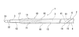
- FIG. 1 is a partially omitted external view of an embodiment of a vascular occlusion balloon catheter using the vascular occlusion balloon of the present invention.
- FIG. 2 is an enlarged external view of the distal end portion of the balloon catheter shown in FIG.
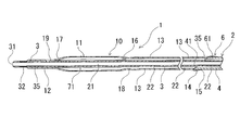
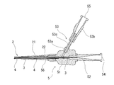
- FIG. 3 is a longitudinal sectional view of FIG. 4 is an enlarged longitudinal sectional view of a proximal end portion of the balloon catheter shown in FIG.
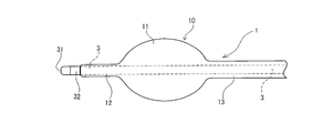
- FIG. 5 is an enlarged external view of a distal end portion when the balloon catheter shown in FIG. 1 is expanded.
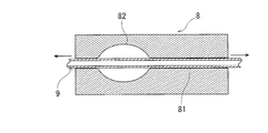
- FIG. 6 is an explanatory diagram for explaining a method of manufacturing a vascular occlusion balloon according to the present invention.
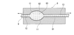
- FIG. 7 is an explanatory diagram for explaining a method of manufacturing a vascular occlusion balloon according to the present invention.
- FIG. 8 is an explanatory diagram for explaining a method of manufacturing a vascular occlusion balloon according to the present invention.
- FIG. 9 is an explanatory diagram for explaining a method of manufacturing a vascular occlusion balloon according to the present invention.
- FIG. 10 is an explanatory diagram for explaining a method of manufacturing a vascular occlusion balloon according to the present invention.
- FIG. 11 is an explanatory diagram for explaining a method of manufacturing a vascular occlusion balloon according to the present invention.
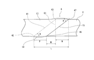
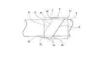
- FIG. 12 is an explanatory view for explaining a fixing portion between the balloon rear end portion and the outer tube front end portion of the balloon catheter of the present invention.
- FIG. 13 is an explanatory view for explaining a fixing portion between the balloon rear end portion and the outer tube front end portion of the balloon catheter of the present invention.
- a vascular occlusion balloon 10 for a vascular occlusion balloon catheter according to the present invention comprises a synthetic resin tube 9 having elasticity and thermoplasticity, and includes a bulging portion 11 formed by plastic deformation, and a bulging portion 11.
- a front-end-side cylindrical portion 12 that is formed on the front end side and has a smaller diameter and thickness than the bulging portion 11 and a rear-end side tube that is formed on the rear end side of the bulging portion 11 and has a smaller diameter and thickness than the bulging portion 11.
- the shape part 13 is provided.
- the bulging portion 11 is shaped into a reduced diameter shape that can be expanded by elastic deformation by applying an internal pressure and has wrinkles 71 extending in the axial direction.
- the bulging portion 11 can be expanded by elastic deformation, the blood vessel can be closed without damaging the blood vessel, and the bulging portion 11 formed by plastic deformation has a wrinkle 71 extending in the axial direction. Since it is shaped into a reduced diameter configuration, it has a low profile and can be inserted into a narrow blood vessel.
- the vascular occlusion balloon catheter 1 of the present invention includes a vascular occlusion balloon 10 and a shaft portion 2 including a main lumen 21 and a balloon expansion lumen 22. Furthermore, the blood vessel occlusion balloon 10 is the above-described blood vessel occlusion balloon 10, and the blood vessel occlusion balloon 10 has a front end side tubular portion 12 and a rear end side tube so that the inside communicates with the balloon dilating lumen 22. The shape portion 13 is fixed to the shaft portion 2.
- the vascular occlusion balloon 10 As the vascular occlusion balloon 10, the vascular occlusion balloon 10 described above is used, and the bulging portion 11 can be expanded by elastic deformation, so that the blood vessel can be occluded without damaging the blood vessel, Since it is formed into a reduced diameter form having wrinkles extending in the axial direction, it has a low profile.
- the vascular occlusion balloon catheter 1 of this embodiment includes a shaft portion 2 and a balloon 10.
- the shaft portion 2 includes an inner tube 3, an outer tube 4, and a hub 5.
- the vascular occlusion balloon catheter 1 of this embodiment is provided coaxially with the inner tube 3 having the main lumen 21 and the inner tube 3, with the distal end at a position retracted by a predetermined length from the distal end of the inner tube 3.
- the outer tube 4 forming the balloon expansion lumen 22 between the inner tube 3 and the outer surface of the inner tube 3 is fixed to the inner tube 3, and the rear tube portion 13 is fixed to the outer tube. 4 and an expandable balloon 10 having an interior communicating with the balloon expansion lumen 22.
- the balloon 10 includes a bulging portion 11 formed by plastic deformation, a distal end side tubular portion 12 having a smaller diameter and a larger thickness than the bulging portion 11, and a bulging portion. 11 and a rear end side tubular portion 13 having a diameter smaller than that of the bulging portion 11 and a wall thickness. Further, the bulging portion 11 is shaped into a reduced diameter shape that can be expanded by elastic deformation by applying an internal pressure and has wrinkles 71 extending in the axial direction.
- the balloon 10 is extensible as shown in FIG. 5, and is shaped into a collapsed reduced diameter configuration having wrinkles 71 extending in the axial direction as shown in FIGS. It is in the state which clings to the outer periphery of 3.
- the bulging portion 11 does not have wrinkles extending in the circumferential direction.
- the bulging portion 11 of the balloon 10 is inflated by the injected liquid and can be in close contact with the inner wall of the blood vessel. Specifically, the bulging portion 11 is restored to a molded form from the reduced diameter form formed by injecting a balloon dilating liquid, and can be expanded (expanded), so that the bulging part 11 is firmly attached to the inner wall of the blood vessel. However, the inner wall is not damaged.
- the bulging portion 11 is formed by stretching at a temperature higher than the glass transition point and lower than the softening point.
- the bulging portion 11 is thinner than the front end side cylindrical portion 12 and the rear end side cylindrical portion 13. And the front end side cylindrical part 12 and the rear end side cylindrical part 13 which were mentioned above are not substantially extended
- the leading end side cylindrical portion side end portion 17 and the rear end side cylindrical portion side end portion 16 of the bulging portion 11 are thickness changing portions that gradually become thinner toward the bulging portion 11.
- the front end side cylindrical portion side end portion 17 and the rear end side cylindrical portion side end portion 16 of the bulging portion 11 are shaped so as to fall inside the bulging portion 11. It is preferable. By doing so, the rising portion of the bulging portion 11 is prevented from becoming an obstacle during advancement in the blood vessel, insertion into the guiding catheter, and storage, and the catheter insertion operation is improved.
- the bulging portion 11 is preferably formed by plastic deformation due to internal pressure partially applied at a temperature not lower than the glass transition point and not higher than the softening point of the synthetic resin as the forming material.
- the shaping is preferably formed by compression using a heat-shrinkable tube and heat setting by heating. By doing in this way, it is shape
- the heat setting is preferably performed by heating near the softening point of the synthetic resin or within 10 degrees or less from the softening point. By doing in this way, without reducing the plastic deformation of the bulging portion, it is surely shaped into a reduced diameter form having wrinkles extending in the axial direction.
- the front end side cylindrical portion 12 is a short cylindrical portion extending with substantially the same outer diameter, and is thicker than the bulging portion 11.
- the rear end side cylindrical portion 13 extends with substantially the same outer diameter, has a longer length in the axial direction than the front end side cylindrical portion 12, and is thicker than the bulging portion 11. It has become a thing.
- the distal end side cylindrical portion 12 has an outer diameter smaller than that of the rear end side cylindrical portion 13 and is fixed to the distal end portion of the inner tube 3. Yes.
- the distal end of the distal cylindrical portion 12 is located at the rear end of the contrast marker 32 or close without reaching the rear end.
- the distal end side cylindrical portion 12 does not cover the contrast marker 32.
- the distal end side cylindrical portion 12 is preferably fixed to the inner tube 3 by heat sealing.
- the rear end side cylindrical portion 13 does not substantially expand even when liquid is injected.
- the rear end side tubular portion 13 forms a part of the balloon expanding lumen 22 by the inner surface thereof and the inner surface of the inner tube 3.
- polyurethane and urethane elastomer for example, polyethylene elastomer, polypropylene elastomer), polyester such as polyethylene terephthalate, soft polyvinyl chloride, polyamide and amide elastomer (for example, polyamide elastomer), fluorine Synthetic resin elastomers such as resin elastomers and ethylene-vinyl acetate copolymers are preferred.
- polyurethane-based thermoplastic elastomers for example, aromatic polyurethane-based thermoplastic elastomers, aliphatic polyurethane-based thermoplastic elastomers, etc. are preferred.
- polyurethane-based thermoplastic elastomers include aromatic and aliphatic thermoplastic elastomer polyurethanes. It is done.
- the material for forming the balloon 10 preferably has a glass transition point of 0 ° C. or less, and particularly preferably ⁇ 10 ° C. or less.
- the softening point (Vicat softening point) is preferably 70 ° C. or higher, and particularly preferably from 80 ° C. to 130 ° C.
- the balloon 10 is higher in flexibility and flexibility than the outer tube 4.
- the balloon 10 is preferably higher in flexibility and flexibility than the inner tube 3 and the outer tube 4.
- the bulging portion side end portion 19 of the front end side cylindrical portion 12 and the bulging portion side end portion 18 of the rear end side cylindrical portion 13 have a small diameter.
- the rear end side cylindrical part 13 is longer than the axial length of the front end side cylindrical part and extends in the rear end part direction. By doing in this way, the full length of a balloon becomes long and a long low profile part can be formed in the front end side part of a catheter.
- the rear end side cylindrical portion 13 has a cylindrical portion (in other words, a sleeve) extending a predetermined length in the rear end direction. It has become.
- the rear end side cylindrical portion 13 includes an inclined rear end surface 15 that is inclined with respect to the central axis of the cylindrical portion.
- the rear end side cylindrical portion 13 of the balloon 10 and the distal end portion of the outer tube 4 described later are fixed by a band-shaped inclined annular fixing portion 6 that is inclined with respect to the central axis of the outer tube 4 and formed airtight. ing.
- the outer diameter of the bulging portion 11 (the outer diameter when the molded form is restored) is preferably 0.90 to 2.10 mm, and particularly preferably 0.93 to 1.00 mm. Further, the outer diameter during expansion (outer diameter that can be expanded) is preferably 3.0 to 15.0 mm, and more preferably 4.0 to 8.0 mm. Further, the length of the bulging portion 11 is preferably 3.5 to 14.5 mm, particularly preferably 4.0 to 5.5 mm.
- the degree of stretching in the radial direction of the bulging portion is preferably 300 to 900%, and the degree of stretching in the axial direction is preferably 200 to 350%.
- the outer diameter of the distal end side cylindrical portion 12 is preferably 0.7 to 1.85 mm, particularly preferably 0.80 to 0.90 mm, and the length is 1.0 to 3.0 mm.
- the thickness is preferably 1.5 to 2.5 mm.
- the outer diameter of the rear end side tubular portion 13 is preferably 0.90 to 2.10 mm, particularly preferably 0.93 to 1.00 mm, and the length is 10 to 60 mm. It is preferably 15 to 30 mm.
- the bulging portion 11 of the balloon 10 is thinner than the front end side cylindrical portion 12 and the rear end side cylindrical portion 13.
- the wall thickness of the bulging portion 11 is preferably 0.03 to 0.18 mm thinner than the rear end side cylindrical portion 13 and the front end side cylindrical portion 12, and particularly 0.04 to 0.11 mm thinner.
- the thickness of the rear end side cylindrical portion 13 and the front end side cylindrical portion 12 is preferably 0.07 to 0.20 mm, and particularly preferably 0.08 to 0.15 mm.
- occlusion balloon 10 is being fixed to the shaft part in the state expanded by the axial direction from the state of FIG. For this reason, as shown in FIGS. 2 and 3, the balloon 10 is slightly extended in the axial direction, and the bulging portion shaped in a reduced diameter form has a smaller diameter. .
- the inner tube 3 is a tube body having a main lumen 21 whose tip is open.
- the main lumen 21 is used for insertion of a guide wire, injection of a chemical solution, and the like.
- the main lumen 21 of the inner tube 3 communicates with the first opening 54 provided in the branch hub 5.
- the inner tube 3 preferably has an outer diameter of 0.60 to 1.60 mm, particularly preferably 0.62 to 0.68 mm, and an inner diameter of 0.40 to 1.30 mm. And particularly preferably 0.43 to 0.50 mm.
- the inner tube 3 is inserted into the outer tube 4, and the tip of the inner tube 3 protrudes from the outer tube 4.
- a second lumen (balloon expansion lumen) 22 is formed between the outer surface of the inner tube 3 and the inner surface of the outer tube 4 and has a sufficient volume.
- a contrast marker 32 is fixed at the distal end (slightly proximal from the distal end 31, near the distal tubular portion 12 of the balloon 10).
- the contrast marker is preferably formed of a radiopaque material (for example, gold, platinum, tungsten, or an alloy thereof, or a silver-palladium alloy, a platinum-iridium alloy, or the like).
- the inner tube 3 is continuous with the first flexible region 3a and the first region 3a from the distal end side, and is flexible, but the first flexible region.
- a second flexible region 3b having a hardness higher than 3a and a third region 3c that is continuous with the second flexible region 3b and has a hardness higher than that of the second flexible region 3b.
- the most flexible first flexible region 3a extends from the distal end of the inner tube 3 in the rear end direction, and the rear end of the first flexible region 3a is an outer portion to be described later. It passes over the belt-like inclined annular fixing portion 6 between the tube 2 and the cylindrical portion of the balloon 4 and is located on the rear end side of a predetermined length.
- the length of the first region 3a is preferably 100 to 350 mm, and particularly preferably 200 to 300 mm.
- the hardness of the first region 3a is preferably 30 to 40D (Shore D hardness).
- the length of the second flexible region 3b that is continuous with the first flexible region 3a is preferably 100 to 350 mm, and particularly preferably 200 to 300 mm.
- the hardness of the second region 3a is preferably 40 to 55D (Shore D hardness), and preferably 5 to 15D (Shore D hardness) higher than the first flexible region.
- the length of the third region 3c continuous with the second flexible region 3b is preferably 500 to 1500 mm, and particularly preferably 800 to 1200 mm.
- the hardness of the third region 3c is preferably 55 to 85D (Shore D hardness), and preferably 15 to 40D (Shore D hardness) hardness higher than that of the second flexible region.
- the outer tube 4 is a tube body that is inserted in the inner tube 3 and located at a portion (a predetermined length base end side) whose tip is retracted by a predetermined length from the tip of the inner tube 3.
- the balloon expanding lumen 22 communicates with a rear end portion of the balloon 10 to be described later, and the rear end of the balloon expanding lumen 22 is provided on the branch hub 5 and is a fluid for inflating the balloon (for example, the balloon It communicates with the second opening 55 of the injection port 53 for injecting an expansion liquid (specifically, an angiographic agent).
- the outer tube 4 preferably has an outer diameter of 0.85 to 2.03 mm, particularly preferably 0.87 to 0.95 mm, and an inner diameter of 0.70 to 1.83 mm. And particularly preferably 0.72 to 0.80 mm.
- the outer tube 4 includes an inclined distal end surface 41 that is inclined with respect to the central axis of the outer tube 4 at the distal end.
- the material for forming the outer tube 4 and the inner tube 3 is preferably a material having a certain degree of hardness and a certain degree of flexibility.
- polyolefins such as polyethylene and polypropylene, polyamides such as polyamide and polyethylene terephthalate, PTFE, Fluorine polymers such as ETFE, PEEK (polyetheretherketone), polyimide, olefin elastomer (eg, polyethylene elastomer, polypropylene elastomer), polyamide elastomer, styrene elastomer (eg, styrene-butadiene-styrene copolymer, styrene) -Isoprene-styrene copolymer, styrene-ethylenebutylene-styrene copolymer), polyurethane, urethane elastomer, fluororesin elastomer Which synthetic resin elast
- the outer tube 4 and the inner tube 3 may be provided with a rigidity imparting body 35.
- a rigidity imparting body a blade formed of a metal wire or a synthetic resin wire is preferable.
- the distal end portion of the outer tube 4 includes the inclined distal end surface 41 that is inclined with respect to the central axis of the outer tube 4, and the balloon 10 has a rear end side tubular portion on the rear end side tubular portion 13.
- An inclined rear end face 15 that is inclined with respect to the central axis of 13 is provided.
- pipe 4 and the rear end side cylindrical part 13 of the balloon 10 have a part which overlaps with the axial direction of a balloon catheter.
- a belt-like inclined annular fixing provided at an overlapping portion of the distal end portion of the outer tube 4 and the rear end side tubular portion 13 of the balloon 10 and inclined with respect to the central axis of the outer tube 4 and formed airtight.
- Part 6 is provided. By doing so, the physical properties of the fixed portion between the rear end portion of the balloon and the distal end portion of the outer tube in the catheter gradually change, and the physical properties near the distal end of the outer tube and the proximal end of the balloon are rapidly changed. No part that changes is formed, there is little occurrence of kinks due to changes in physical properties, and there is good operability for insertion into blood vessels.
- the outer tube 4 and the balloon 10 are fixed by the inclined annular fixing portion 6. Since the rear end side cylindrical portion 13 of the balloon 10 is more flexible and flexible than the distal end portion of the outer tube 4, the forming part of the inclined annular fixing portion 6 is from the rear end side to the distal end side. As the flexibility and flexibility become higher, a sudden physical property change point in the vicinity of the distal end portion of the outer tube 4 is not formed, and kink is prevented from being generated and has good deformability. Yes.
- the rear end portion of the rear end side tubular portion 13 of the balloon 10 is an enlarged diameter portion 14 (in other words, an inclined enlarged diameter portion, an inclined bulging portion),
- the rear end surface 15 is an inclined rear end surface that is inclined at a predetermined angle with respect to the central axis of the rear end side tubular portion 13 (outer tube 4).
- the distal end portion of the outer tube 4 enters the rear end side tubular portion 13 whose diameter has been expanded, and this entry portion is a portion where the distal end portion of the outer tube 4 and the rear end side tubular portion 13 of the balloon 10 overlap. Is forming.
- the outer tube 4 has a slightly smaller outer diameter than the rear end side cylindrical portion 13 of the balloon 10, and the rear end side cylindrical portion 13 of the balloon 10 is in a bulged state.
- the inclined rear end surface 15 of the balloon 10 and the inclined front end surface 41 of the outer tube 4 are substantially parallel or have different inclination angles with respect to the central axis of the outer tube. 25 degrees or less, preferably 20 degrees or less.
- the inclination angle A with respect to the central axis of the rear end side tubular portion 13 (outer tube 4) of the inclined rear end face 15 of the balloon 10 is preferably 20 degrees to 30 degrees, and more preferably 22 degrees to 28 degrees.
- the inclination angle B of the inclined front end surface 41 of the outer tube 4 with respect to the central axis of the outer tube 4 is preferably 30 ° to 45 °, and particularly preferably 35 ° to 43 °.
- pipe 4 which entered into the rear end side cylindrical part 13 in which the diameter of the balloon 10 is expanded is fixed to the balloon 10 in an airtight manner, and forms a belt-like inclined annular fixing part 6.
- the inclined annular fixing portion 6 has an annular fixing surface 61.
- the annular fixing portion 61 is formed on the entire inner surface of the rear end portion 14 of the balloon 10 that contacts the outer surface of the distal end portion of the outer tube 4 of the inclined annular fixing portion 6.
- a non-fixed portion that does not affect the airtightness between the two may be included.
- the annular fixing portion 61 has substantially the same width or gradually becomes wider toward the rear end.
- the annular fixing portion 61 is gradually widened toward the rear end.
- the imaginary line connecting the tip 42 of the inclined front end surface 41 of the outer tube 4 and the tip 46 of the inclined rear end surface 15 of the balloon 10 is substantially parallel to the central axis of the outer tube 4. It has become. That is, the distal end 42 of the inclined distal end surface 41 of the outer tube 4 is positioned almost in front of the distal end 46 of the inclined rear end surface 15 of the balloon 10.
- an imaginary line connecting the rear end 43 of the inclined front end surface 41 of the outer tube 4 and the rear end 47 of the inclined rear end surface 15 of the balloon 10 is substantially parallel to the central axis of the outer tube 4. That is, the rear end 43 of the inclined front end surface 41 of the outer tube 4 is positioned substantially in front of the rear end 47 of the rear end surface 15 of the balloon 10 in the front end direction. For this reason, a narrow portion is not formed in the annular fixing portion 61.
- the distal end 46 of the inclined rear end surface 15 of the balloon 10 is located on the distal end side from the rear end 43 of the inclined distal end surface 41 of the outer tube 4.
- the physical property of the inclined annular fixing portion 6 continuously changes. Since the rear end side cylindrical portion 13 of the balloon 10 is more flexible and flexible than the distal end portion of the outer tube 4, the forming part of the inclined annular fixing portion 6 is from the rear end side to the distal end side. Flexibility and softness gradually become higher.
- the portion where the rear end portion of the balloon 10 covers the front end portion of the outer tube 4 is increased from the rear end side, and the rear end of the inclined front end surface 41 of the outer tube 4 is increased.
- the rear end side cylindrical portion 13 of the balloon 10 continues to increase in cross-sectional area perpendicular to the axial direction, but the cross-sectional area perpendicular to the axial direction of the distal end portion of the outer tube 4 is Decrease.
- tip 46 of the inclined surface 15 of the rear end side cylindrical part 13 of the balloon 10 the cross section of the rear end side cylindrical part 13 becomes cyclic
- the inclined annular fixing portion 6 is entirely formed on the cut surface orthogonal to the central axis of the outer tube 4 so that the rear end side tubular portion 13 of the balloon 10 and the distal end portion of the outer tube 4 are aligned. Both have no annular part.
- the distance P between the distal end 42 of the outer tube 4 and the distal end 46 of the inclined rear end face 15 of the balloon 10 in FIG. 12 is preferably 0.5 to 1.5 mm, particularly 0.6 to 1.0 mm. It is preferable that The distance N between the rear end 43 of the inclined front end face 41 of the outer tube 4 and the rear end 47 of the inclined rear end face 15 of the balloon 10 is preferably 0.5 to 4.0 mm, particularly 0.6. It is preferable that it is -1.0 mm.
- the axial length L of the inclined annular fixing portion 6 (in other words, the distance L between the distal end 42 of the outer tube 4 and the rear end 47 of the inclined rear end face 15 of the balloon 10) is 2.0 to 8.0 mm.
- the thickness is preferably 2.3 to 3.5 mm.
- the distance M between the rear end 43 of the inclined front end face 41 of the outer tube 4 and the front end 46 of the inclined rear end face 15 of the balloon 10 is preferably 0.5 to 2.5 mm, particularly 0.8 to It is preferable that it is 1.5 mm.
- the distance M between the rear end 43 of the inclined distal end surface 41 of the outer tube 4 and the distal end 46 of the inclined rear end surface 15 of the balloon 10 is 0, that is, the inclined distal end of the outer tube 4 as in the embodiment shown in FIG.
- the rear end 43 of the surface 41 and the tip 46 of the inclined rear end surface 15 of the balloon 10 may be located at the same position in the axial direction of the outer tube 4.
- the rear end 43 of the inclined front end surface 41 of the outer tube 4 is preferably not located on the front end side of the front end 46 of the inclined rear end surface 15 of the balloon 10.
- the inclined annular fixing portion 6 includes an overlapping portion and about 2 mm before and after the distal end portion of the outer tube 4 is inserted into the rear end side tubular portion 13 of the balloon 10.
- a heat-shrinkable tube is fitted on the heat-shrinkable tube, and the heat-shrinkable tube is heated from the outer surface by the heat mold 7 so as to be fused together.
- the outer edge of the inclined front end surface of the outer tube 4 is rounded with no edges due to melting.
- melting process as shown in FIG. 13, you may carry out so that the front-end
- fusion part with the rear-end part of the balloon 10 can be formed in the front-end
- the rear end side tubular portion 13 of the balloon 10 in the portion where the outer tube 4 does not exist is heated and compressed by the heat shrinkable tube. This prevents the thin portion from being formed in the seal portion.
- the branch hub 5 has a first opening 54 communicating with the main lumen 21, an inner tube hub 52 fixed to the rear end portion of the inner tube 3, and a balloon expanding lumen 22.
- a second opening 55 provided at the end of the injection port 53 and an outer tube hub 51 fixed to the rear end of the outer tube 4.
- the outer tube hub 51 and the inner tube hub 52 is fixed.
- the outer tube hub 51 and the inner tube hub 52 are fixed by inserting and joining the inner tube 3 from the rear end of the outer tube hub 51 attached to the base end portion of the outer tube 4.
- the branch hub 5 is provided with a bending prevention tube 56 that encloses the proximal end portion of the outer tube 4 and the distal end portion of the branch hub 5.
- the injection port 53 is formed by a branch port 53a extending from the side wall of the outer pipe hub 51, an injection port hub 53b, and a connection tube 53c that connects the branch port 53a and the injection port hub 53b.
- a material for forming the branch hub and the injection port hub thermoplastic resins such as polycarbonate, polyamide, polysulfone, polyarylate, and methacrylate-butylene-styrene copolymer can be preferably used.
- the connection tube a flexible or soft synthetic resin tube is used.
- the structure of the balloon catheter is not limited to the one described above, and has a guide wire insertion port that communicates with the guide wire lumen in the middle portion of the balloon catheter (the rear end side from the inclined annular fixing portion 6).
- the balloon catheter of the present invention is preferably applied to a catheter for drug administration with a vascular occlusion function, but is not limited thereto, and can be applied to a PTCA catheter, a balloon expandable stent delivery system, and the like. it can.
- the method for producing a balloon for vascular occlusion according to the present invention includes a step of preparing a tube made of a synthetic resin having elasticity and thermoplasticity, a step of preparing a molding die having a balloon bulging portion molding portion therein, and a molding die Place a synthetic resin tube on the plastic resin, inject the liquid into the synthetic resin tube in an environment that is above the glass transition point and below the softening point of the synthetic resin, and partially swell the synthetic resin tube.
- a bulging part forming step for forming a bulging part that is brought into contact with the molding part and plastically deformed, and detaching the synthetic resin tube formed with the bulging part from the molding die and reducing the amount of injected liquid.
- the diameter of the bulge is reduced by its elastic deformation and the liquid filling state is maintained, and the liquid filled state is maintained, and the bulged part having a reduced diameter and a heat-shrinkable tube are fitted around the bulged part.
- heat shrink tube Heat above the shrinking temperature and within the softening point of the synthetic resin or within 10 degrees or less from the softening point, and use the shrinkage of the heat shrinkable tube to shape the bulging part into a reduced diameter form having wrinkles extending in the axial direction.
- the reduced diameter shape shaping step is performed.
- the step of preparing the synthetic resin tube is, for example, a thermoplastic synthetic resin having elasticity described as a forming material of the balloon 10, specifically, a thermoplastic synthetic resin elastomer, and the glass transition point and the softening point described above (
- a tube 9 made of a material having a Vicat softening point is prepared.
- the outer diameter of the tube is preferably 0.90 to 2.17 mm, particularly preferably 0.93 to 1.00 mm, and the inner diameter is preferably 0.70 to 1.93 mm. 0.73-0.80 mm is preferable.
- molding part of a balloon inside is performed.
- the mold 8 having the bulging part molding part for example, a mold as shown in FIG.
- the molding die 8 has a through-passage 81 through which the tube 9 can be inserted, and a bulging portion molding portion 82 provided in the middle thereof.
- the bulging portion molding portion 82 is a substantially spherical recess.
- the step of forming the bulging portion on the tube 9 is performed in an environment not lower than the glass transition point and not higher than the softening point of the synthetic resin that is the tube forming material, for example, at a normal temperature.
- a material for forming the tube 9 a material having a normal temperature (15 to 30 ° C.) region having a glass transition point or more and a softening point or less is usually used. Therefore, the mold 8 and the tube 9 to be used are not heated. Used at room temperature.
- a synthetic resin tube is placed in a mold.
- a state in which a slight tension is applied in the direction of the arrow (in other words, a state in which it is pulled loosely) is set.
- a liquid 83 for example, water
- the tube portion located in the bulging portion forming portion 82 of the mold 8 is the bulging portion forming portion 82 of the forming die.
- a pressure is applied in the tube 9 until it contacts the inner surface.
- the tube portion located in the bulging portion molding portion 82 of the mold 8 is initially elastically deformed and plastically deformed when the elastic deformation limit is exceeded, and the bulging portion 11 is formed.
- a front end side cylindrical portion 12 is formed on the front end side of the bulging portion 11, and a rear end side cylindrical portion 13 is formed on the rear end side.
- a diameter reducing process (bulging part diameter reducing process) of the bulging part 11 formed in the tube 9 is performed.
- the synthetic resin tube 9 in which the bulging portion 11 is formed is detached from the mold 8 as shown in FIG.
- the injected liquid 83 is reduced in volume, the diameter of the bulging portion 11 is reduced by its elastic deformation, and the filling state of the liquid 83 is maintained.
- the bulging portion 11 has a smaller diameter than the outer diameter in contact with the bulging portion molding portion 82 of the mold 8.
- the outer diameter of the bulging portion 11 in contact with the bulging portion molding portion 82 of the mold 8 is preferably 4.0 to 15.0 mm, and particularly 4.5 to 6.0 mm.
- the outer diameter of the bulging portion 11 after the bulging portion diameter reducing step is 3.3 to 3 than the outer diameter of the bulging portion 11 in contact with the bulging portion molding portion 82 of the mold 8.
- the diameter is preferably 12.5 mm, and particularly preferably 3.8 to 4.3 mm.
- a reduced diameter shape shaping step of the bulged portion 11 reduced in diameter in the bulged portion reduced diameter step is performed.
- the reduced diameter shape shaping step is performed in a state where the liquid filling state in the tube 9 is maintained.
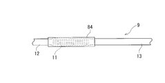
- the heat shrinkable tube 84 is fitted so as to enclose the bulged portion 11 having a reduced diameter and the front and back thereof.
- the bulging portion 11 reduced in diameter in the bulging portion diameter reducing step is pulled on both sides in the axial direction and further reduced in diameter.
- the entire bulging portion 11 including the heat shrinkable tube 84 and the front and back thereof are above the shrinkage temperature of the heat shrinkable tube and near the softening point or the softening point of the synthetic resin which is the forming material of the tube 9. To within 10 degrees. If it is such temperature, the heat contraction of a heat contraction tube will express reliably, and although the bulging part 11 is heated, it does not soften. As a result, as shown in FIG. 10, the heat shrinkable tube 84 contracts and compresses the bulging portion 11, and coupled with the resistance of the liquid 83 filled therein, the bulging portion 11 is moved in the axial direction. As shown in FIG. 11, it is shaped into the reduced diameter form having extending wrinkles.
- the leading end side cylindrical portion side end portion 17 and the trailing end side cylindrical portion side end portion 16 of the bulging portion 11 Shaped into a collapsed form.
- the outer diameter of the heat-shrinkable tube is preferably 0.4 to 0.6 mm larger than the outer diameter of the bulging portion 11 after the bulging portion diameter reducing step. It is preferable that the front end side cylindrical portion 12 and the rear end side cylindrical portion 13 formed before and after the protruding portion 11 have the same diameter as the outer diameter or smaller than the outer diameter by 0.03 to 0.06 mm.
- the heat-shrinkable tube 84 a tube that is thermally shrunk so as to have a slightly smaller diameter than the outer diameter of the front end side cylindrical portion 12 and the rear end side cylindrical portion 13 is used.
- the distal end side cylindrical portion 12 has a bulging portion side end portion 19 that has a smaller diameter than the other portions of the distal end side cylindrical portion 12.
- the bulging portion side end portion 18 has a smaller diameter than other portions of the rear end side cylindrical portion 13.
- the length of the heat shrinkable tube 84 is longer than the length in the axial direction of the bulging portion forming portion 82. Specifically, it is 8 to 12 mm, preferably 9 to 11 mm longer than the axial length of the bulging portion molding portion 82.
- the heat shrinkable tube 84 is produced by producing a small diameter tube and expanding it in the radial direction.
- a material for forming the heat-shrinkable tube 84 polyolefins such as polyethylene and polypropylene, EAA (ethylene-acrylic acid copolymer), EVA (ethylene-vinyl acetate copolymer), silicone resin, fluorine resin, and the like can be used. Then, the heat-shrinkable tube 84 is detached from the tube 9 and the liquid in the tube 9 is discharged, whereby the manufacturing process of the vascular occlusion balloon is completed.
- Example 1 Polyurethane elastomer (polyether-type polyurethane, Pellethane 2363-80AE, manufactured by The Lubrizol Corporation, breaking strength 29 Mpa, breaking elongation 650%, Vicat softening point 81.0 ° C., glass transition point as balloon forming material ⁇ 47 ° C., melting temperature 188 ° C.).
- a tube having an outer diameter of 0.95 mm, an inner diameter of 0.75 mm, and a length of 100 mm was produced from the polyurethane elastomer.
- molding die which has an internal form as shown in FIG. 6 was prepared.
- the inner diameter of the through-passage in the molding die is 1.30 mm
- the length of the bulge portion forming portion is 6.0 mm
- the inner diameter of the maximum diameter portion of the bulge portion forming portion is 4.0 mm. there were.
- a heat shrinkable tube made of a fluororesin and having an inner diameter before shrinkage of 1.21 mm, an inner diameter after heat shrinkage of 0.89 mm, a length of 10 mm, and a heat shrinkage temperature of 70 ° C. was prepared. Then, the tube is placed in the mold shown in FIG. 6 and filled with water in the state where both ends are pulled at room temperature. Then, an internal pressure is applied to closely contact the inner surface of the mold. The bulge was formed.
- the stretching ratio in the radial direction when the bulging portion was in close contact with the inner surface of the mold was about 6.3 times.
- the tube 9 in which the bulging part 11 was formed was taken out of the mold, the injected water was reduced, and the bulging part 11 was reduced in diameter by its elastic deformation.
- the outer diameter of the bulging part in this state was 1.1 mm.
- the tube which has the bulging part with which water was filled was pulled from the axial direction both sides, and while the diameter of the bulging part was further reduced, it was set as the form which has a wrinkle extended in an axial direction.
- the heat contraction tube was arrange
- the outer diameter of the bulged portion thus shaped was 1.4 mm, and both end portions of the bulged portion were shaped so as to fall to the center side of the bulged portion. Further, four wrinkles extending in the axial direction were formed in the bulging portion.
- the formed balloon has a thickness of about 35 ⁇ m at the central portion of the balloon bulge, the thickness of the front end tubular portion is 100 ⁇ m, and the thickness of the rear end tubular portion is: It was 100 ⁇ m.
- Example 1 A balloon of a comparative example was produced in the same manner as in Example 1 except that the step of shaping into a reduced diameter form using the heat-shrinkable tube in Example 1 was not performed.
- the balloon bulge was entirely in the shape of a rugby ball, and there were no wrinkles on the outer surface.
- the outer diameter of the bulging portion was 2.0 mm, and both end portions of the bulging portion were suddenly raised in the radial direction.
- Example 1 The balloon of Example 1 was fitted on a synthetic resin tube (resin name Pellethane 2363-55DE, manufactured by The Lubrizol Corporation, outer diameter 0.90 mm, inner diameter 0.75 mm, length 600 mm), and the front end side cylindrical portion and the rear end The rear end portion of the side cylindrical portion was fixed by heat sealing, and the balloon-attached tube body of Experimental Example 1 was produced.
- a synthetic resin tube resin name Pellethane 2363-55DE, manufactured by The Lubrizol Corporation, outer diameter 0.90 mm, inner diameter 0.75 mm, length 600 mm
- Experimental example 2 The balloon of Comparative Example 1 was fitted on a synthetic resin tube (resin name Pellethane 2363-55DE, manufactured by The Lubrizol Corporation, outer diameter 0.90 mm, inner diameter 0.75 mm, length 600 mm), and the front end side cylindrical portion and the rear end The rear end portion of the side cylindrical portion was fixed by heat sealing, and the balloon-attached tube body of Experimental Example 2 was produced.
- a passage experiment was performed.
- An angiographic catheter (Termo Clinical Supply Co., Ltd., outer diameter 1.40 mm, inner diameter 1.05 mm) with a curved tip was prepared.
- Tubes with balloons of Experimental Examples 1 and 2 were inserted into the angiographic catheter and the balloon portion was exposed from the distal end of the catheter. And the tube body with a balloon of Experimental example 1 and Experimental example 2 inserted in the catheter was 100 mm / min. The maximum value of the passage resistance of the bulging part when 100 mm was pulled at a speed of was measured. In the tube body with the balloon of Experimental Example 1, the passage resistance was 16.77 gf, and with the tube body with the balloon of Experimental Example 2, the passage resistance was 25.3 gf. wear.
- the vascular occlusion balloon for the vascular occlusion balloon catheter of the present invention is as follows.
- a blood vessel occlusion balloon for a blood vessel occlusion balloon catheter wherein the blood vessel occlusion balloon is made of a synthetic resin tube having elasticity and thermoplasticity, and a bulging portion formed by plastic deformation; Formed on the leading end side of the bulging portion, and having a smaller diameter and thickness than the bulging portion, and on the rear end side of the bulging portion, and having a smaller diameter and thickness than the bulging portion.
- the bulging portion is shaped in a reduced diameter shape having wrinkles extending in the axial direction, and can be expanded by elastic deformation by applying an internal pressure.
- a vascular occlusion balloon for a vascular occlusion balloon catheter is provided.
- the bulging portion can be expanded by elastic deformation, so that the blood vessel can be closed without damaging the blood vessel, and the bulging portion formed by plastic deformation is Since it is formed into a reduced diameter form having wrinkles extending in the axial direction, it has a low profile and can be inserted into a small diameter blood vessel.
- the said front end side cylindrical part side edge part and said rear end side cylindrical part side edge part of the said bulging part are shaped in the form which fell to the inner side of the said bulging part (1).
- the balloon occlusion balloon catheter of the present invention is as follows. (8) A vascular occlusion balloon catheter comprising a vascular occlusion balloon and a shaft portion including a main lumen and a balloon dilating lumen, wherein the vascular occlusion balloon is any of the above (1) to (7) The vascular occlusion balloon, and the distal end side cylindrical portion and the rear end side cylindrical portion are connected to the shaft portion so that the interior thereof communicates with the balloon dilating lumen. A fixed vascular occlusion balloon catheter.
- the vascular occlusion balloon described above is used as the vascular occlusion balloon, and the bulging portion can be expanded by elastic deformation, so that the blood vessel can be occluded without damaging the blood vessel, and in the axial direction. Since it is shaped into a reduced diameter form having extending wrinkles, it has a low profile and can be inserted into a narrow blood vessel.
- the shaft portion includes an inner tube and an outer tube that is provided coaxially with the inner tube and has a distal end at a position retracted by a predetermined length from the distal end of the inner tube.
- the rear end side cylindrical portion of the vascular occlusion balloon includes an inclined rear end surface that is inclined with respect to a central axis of the rear end side cylindrical portion, and a distal end portion of the outer tube is An inclined distal end surface that is inclined with respect to the central axis of the outer tube, and the distal end portion of the outer tube and the rear end portion of the tubular portion on the rear end side of the vascular occlusion balloon are the balloon catheter.
- the distal end portion of the outer tube and the rear end side tubular portion of the vascular occlusion balloon are provided in the overlapping portion, and are inclined with respect to the central axis of the outer tube.
- the manufacturing method of the blood vessel occlusion balloon for the blood vessel occlusion balloon catheter of the present invention is as follows. (13) A method for producing a vascular occlusion balloon for a vascular occlusion balloon catheter, Preparing a tube made of synthetic resin having elasticity and thermoplasticity; A step of preparing a mold having a balloon bulge forming part inside; The synthetic resin tube is disposed in the mold, and a liquid is injected into the synthetic resin tube in an environment not lower than the glass transition point and not higher than the softening point of the synthetic resin.
- the bulging portion reduced in diameter by the bulging portion diameter reducing step is further pulled in the axial direction and further reduced in diameter, and the heating is performed while maintaining the pulled state.
Landscapes
- Health & Medical Sciences (AREA)
- Life Sciences & Earth Sciences (AREA)
- Heart & Thoracic Surgery (AREA)
- Engineering & Computer Science (AREA)
- Anesthesiology (AREA)
- Biophysics (AREA)
- Pulmonology (AREA)
- Child & Adolescent Psychology (AREA)
- Biomedical Technology (AREA)
- Hematology (AREA)
- Animal Behavior & Ethology (AREA)
- General Health & Medical Sciences (AREA)
- Public Health (AREA)
- Veterinary Medicine (AREA)
- Vascular Medicine (AREA)
- Manufacturing & Machinery (AREA)
- Media Introduction/Drainage Providing Device (AREA)
Applications Claiming Priority (2)
| Application Number | Priority Date | Filing Date | Title |
|---|---|---|---|
| JP2012-032130 | 2012-02-16 | ||
| JP2012032130 | 2012-02-16 |
Publications (1)
| Publication Number | Publication Date |
|---|---|
| WO2013122003A1 true WO2013122003A1 (fr) | 2013-08-22 |
Family
ID=48984115
Family Applications (1)
| Application Number | Title | Priority Date | Filing Date |
|---|---|---|---|
| PCT/JP2013/053066 Ceased WO2013122003A1 (fr) | 2012-02-16 | 2013-02-08 | Ballonnet pour cathéter à ballonnet d'occlusion vasculaire, cathéter à ballonnet d'occlusion vasculaire, et procédé de production de ballonnet pour cathéter à ballonnet d'occlusion vasculaire |
Country Status (1)
| Country | Link |
|---|---|
| WO (1) | WO2013122003A1 (fr) |
Cited By (3)
| Publication number | Priority date | Publication date | Assignee | Title |
|---|---|---|---|---|
| CN111685809A (zh) * | 2020-07-03 | 2020-09-22 | 重庆橙壹科技有限公司 | 一个改进的用于胃肠外科的取物器 |
| CN113384391A (zh) * | 2021-06-30 | 2021-09-14 | 甘肃省人民医院 | 一种流量可控的造口清洗装置 |
| CN114728151A (zh) * | 2019-12-26 | 2022-07-08 | 株式会社钟化 | 球囊导管的制造方法以及树脂制医用球囊的制造装置 |
Citations (6)
| Publication number | Priority date | Publication date | Assignee | Title |
|---|---|---|---|---|
| JPH0370575A (ja) * | 1989-07-18 | 1991-03-26 | Baxter Internatl Inc | バルーンカテーテル |
| JPH11347128A (ja) * | 1998-06-08 | 1999-12-21 | Toray Ind Inc | バルーン付カテーテル |
| JP2000217924A (ja) * | 1999-02-01 | 2000-08-08 | Kanegafuchi Chem Ind Co Ltd | 拡張カテーテル用拡張体およびその製造方法 |
| JP2001269410A (ja) * | 2000-03-24 | 2001-10-02 | Aisin Seiki Co Ltd | バルーンカテーテル |
| JP2004000010U (ja) * | 1991-09-12 | 2004-07-29 | アドバンスド、カーディオバスキュラー、システムズ、インコーポレーテッド | 限定された範囲の弾性的な膨張を示す膨張性部分を有する膨張カテーテル |
| JP2008173500A (ja) * | 2008-04-04 | 2008-07-31 | Kaneka Corp | バルーン及びバルーンカテーテル |
-
2013
- 2013-02-08 WO PCT/JP2013/053066 patent/WO2013122003A1/fr not_active Ceased
Patent Citations (6)
| Publication number | Priority date | Publication date | Assignee | Title |
|---|---|---|---|---|
| JPH0370575A (ja) * | 1989-07-18 | 1991-03-26 | Baxter Internatl Inc | バルーンカテーテル |
| JP2004000010U (ja) * | 1991-09-12 | 2004-07-29 | アドバンスド、カーディオバスキュラー、システムズ、インコーポレーテッド | 限定された範囲の弾性的な膨張を示す膨張性部分を有する膨張カテーテル |
| JPH11347128A (ja) * | 1998-06-08 | 1999-12-21 | Toray Ind Inc | バルーン付カテーテル |
| JP2000217924A (ja) * | 1999-02-01 | 2000-08-08 | Kanegafuchi Chem Ind Co Ltd | 拡張カテーテル用拡張体およびその製造方法 |
| JP2001269410A (ja) * | 2000-03-24 | 2001-10-02 | Aisin Seiki Co Ltd | バルーンカテーテル |
| JP2008173500A (ja) * | 2008-04-04 | 2008-07-31 | Kaneka Corp | バルーン及びバルーンカテーテル |
Cited By (3)
| Publication number | Priority date | Publication date | Assignee | Title |
|---|---|---|---|---|
| CN114728151A (zh) * | 2019-12-26 | 2022-07-08 | 株式会社钟化 | 球囊导管的制造方法以及树脂制医用球囊的制造装置 |
| CN111685809A (zh) * | 2020-07-03 | 2020-09-22 | 重庆橙壹科技有限公司 | 一个改进的用于胃肠外科的取物器 |
| CN113384391A (zh) * | 2021-06-30 | 2021-09-14 | 甘肃省人民医院 | 一种流量可控的造口清洗装置 |
Similar Documents
| Publication | Publication Date | Title |
|---|---|---|
| JP6205550B2 (ja) | バルーンカテーテル | |
| EP3795199B1 (fr) | Cathéter à ballonnet | |
| EP0597506B1 (fr) | Cathéter muni d'un élément expansible et procédé pour sa fabrication | |
| CN208741719U (zh) | 一种球囊扩张导管 | |
| JP6348486B2 (ja) | バルーンカテーテル、およびバルーンカテーテルの製造方法 | |
| EP3342446B1 (fr) | Ballonnet pour cathéter, cathéter à ballonnet, et matrice de moulage | |
| JP6682726B2 (ja) | 血管閉塞用バルーンカテーテル | |
| CN111670060A (zh) | 球囊导管 | |
| WO2011162100A1 (fr) | Dispositif médical | |
| CN117482365B (zh) | 球囊扩张导管 | |
| WO2013146306A1 (fr) | Cathéter à ballon pour obturation de vaisseau sanguin | |
| JP2011152181A (ja) | バルーンカテーテル | |
| US8376992B2 (en) | Balloon catheter and sheath fabrication method | |
| JPH0889588A (ja) | カテーテル | |
| JP6201123B2 (ja) | バルーンカテーテル | |
| JP6749847B2 (ja) | バルーンカテーテル | |
| WO2006118103A1 (fr) | Ensemble de pompage a ballonnet intra-aortique | |
| WO2014122759A1 (fr) | Procédé d'amorçage de cathéter à ballonnet | |
| JP6205549B2 (ja) | バルーンカテーテル | |
| JP2018149082A (ja) | 医療用長尺体 | |
| JP5401815B2 (ja) | 体内留置用バルーンカテーテル | |
| JP2013070882A (ja) | バルーンカテーテル | |
| JP2005329063A (ja) | ダイレータ | |
| JP2004121276A (ja) | バルーンカテーテル及びその製造方法 | |
| CN115430015B (zh) | 导尿装置 |
Legal Events
| Date | Code | Title | Description |
|---|---|---|---|
| 121 | Ep: the epo has been informed by wipo that ep was designated in this application |
Ref document number: 13748496 Country of ref document: EP Kind code of ref document: A1 |
|
| NENP | Non-entry into the national phase |
Ref country code: DE |
|
| 122 | Ep: pct application non-entry in european phase |
Ref document number: 13748496 Country of ref document: EP Kind code of ref document: A1 |
|
| NENP | Non-entry into the national phase |
Ref country code: JP |