WO2013122010A1 - 電池用セパレータ、および、電池用セパレータの製造方法 - Google Patents
電池用セパレータ、および、電池用セパレータの製造方法 Download PDFInfo
- Publication number
- WO2013122010A1 WO2013122010A1 PCT/JP2013/053107 JP2013053107W WO2013122010A1 WO 2013122010 A1 WO2013122010 A1 WO 2013122010A1 JP 2013053107 W JP2013053107 W JP 2013053107W WO 2013122010 A1 WO2013122010 A1 WO 2013122010A1
- Authority
- WO
- WIPO (PCT)
- Prior art keywords
- battery separator
- film
- heat
- resin
- air
- Prior art date
- Legal status (The legal status is an assumption and is not a legal conclusion. Google has not performed a legal analysis and makes no representation as to the accuracy of the status listed.)
- Ceased
Links
Classifications
-
- H—ELECTRICITY
- H01—ELECTRIC ELEMENTS
- H01M—PROCESSES OR MEANS, e.g. BATTERIES, FOR THE DIRECT CONVERSION OF CHEMICAL ENERGY INTO ELECTRICAL ENERGY
- H01M50/00—Constructional details or processes of manufacture of the non-active parts of electrochemical cells other than fuel cells, e.g. hybrid cells
- H01M50/40—Separators; Membranes; Diaphragms; Spacing elements inside cells
- H01M50/403—Manufacturing processes of separators, membranes or diaphragms
-
- B—PERFORMING OPERATIONS; TRANSPORTING
- B32—LAYERED PRODUCTS
- B32B—LAYERED PRODUCTS, i.e. PRODUCTS BUILT-UP OF STRATA OF FLAT OR NON-FLAT, e.g. CELLULAR OR HONEYCOMB, FORM
- B32B27/00—Layered products comprising a layer of synthetic resin
- B32B27/18—Layered products comprising a layer of synthetic resin characterised by the use of special additives
- B32B27/20—Layered products comprising a layer of synthetic resin characterised by the use of special additives using fillers, pigments, thixotroping agents
- B32B27/205—Layered products comprising a layer of synthetic resin characterised by the use of special additives using fillers, pigments, thixotroping agents the fillers creating voids or cavities, e.g. by stretching
-
- H—ELECTRICITY
- H01—ELECTRIC ELEMENTS
- H01M—PROCESSES OR MEANS, e.g. BATTERIES, FOR THE DIRECT CONVERSION OF CHEMICAL ENERGY INTO ELECTRICAL ENERGY
- H01M50/00—Constructional details or processes of manufacture of the non-active parts of electrochemical cells other than fuel cells, e.g. hybrid cells
- H01M50/40—Separators; Membranes; Diaphragms; Spacing elements inside cells
- H01M50/409—Separators, membranes or diaphragms characterised by the material
- H01M50/411—Organic material
- H01M50/414—Synthetic resins, e.g. thermoplastics or thermosetting resins
- H01M50/417—Polyolefins
-
- B—PERFORMING OPERATIONS; TRANSPORTING
- B32—LAYERED PRODUCTS
- B32B—LAYERED PRODUCTS, i.e. PRODUCTS BUILT-UP OF STRATA OF FLAT OR NON-FLAT, e.g. CELLULAR OR HONEYCOMB, FORM
- B32B27/00—Layered products comprising a layer of synthetic resin
- B32B27/32—Layered products comprising a layer of synthetic resin comprising polyolefins
-
- B—PERFORMING OPERATIONS; TRANSPORTING
- B32—LAYERED PRODUCTS
- B32B—LAYERED PRODUCTS, i.e. PRODUCTS BUILT-UP OF STRATA OF FLAT OR NON-FLAT, e.g. CELLULAR OR HONEYCOMB, FORM
- B32B27/00—Layered products comprising a layer of synthetic resin
- B32B27/32—Layered products comprising a layer of synthetic resin comprising polyolefins
- B32B27/322—Layered products comprising a layer of synthetic resin comprising polyolefins comprising halogenated polyolefins, e.g. PTFE
-
- H—ELECTRICITY
- H01—ELECTRIC ELEMENTS
- H01M—PROCESSES OR MEANS, e.g. BATTERIES, FOR THE DIRECT CONVERSION OF CHEMICAL ENERGY INTO ELECTRICAL ENERGY
- H01M50/00—Constructional details or processes of manufacture of the non-active parts of electrochemical cells other than fuel cells, e.g. hybrid cells
- H01M50/40—Separators; Membranes; Diaphragms; Spacing elements inside cells
- H01M50/409—Separators, membranes or diaphragms characterised by the material
- H01M50/411—Organic material
- H01M50/414—Synthetic resins, e.g. thermoplastics or thermosetting resins
- H01M50/423—Polyamide resins
-
- H—ELECTRICITY
- H01—ELECTRIC ELEMENTS
- H01M—PROCESSES OR MEANS, e.g. BATTERIES, FOR THE DIRECT CONVERSION OF CHEMICAL ENERGY INTO ELECTRICAL ENERGY
- H01M50/00—Constructional details or processes of manufacture of the non-active parts of electrochemical cells other than fuel cells, e.g. hybrid cells
- H01M50/40—Separators; Membranes; Diaphragms; Spacing elements inside cells
- H01M50/409—Separators, membranes or diaphragms characterised by the material
- H01M50/411—Organic material
- H01M50/414—Synthetic resins, e.g. thermoplastics or thermosetting resins
- H01M50/426—Fluorocarbon polymers
-
- H—ELECTRICITY
- H01—ELECTRIC ELEMENTS
- H01M—PROCESSES OR MEANS, e.g. BATTERIES, FOR THE DIRECT CONVERSION OF CHEMICAL ENERGY INTO ELECTRICAL ENERGY
- H01M50/00—Constructional details or processes of manufacture of the non-active parts of electrochemical cells other than fuel cells, e.g. hybrid cells
- H01M50/40—Separators; Membranes; Diaphragms; Spacing elements inside cells
- H01M50/409—Separators, membranes or diaphragms characterised by the material
- H01M50/446—Composite material consisting of a mixture of organic and inorganic materials
-
- H—ELECTRICITY
- H01—ELECTRIC ELEMENTS
- H01M—PROCESSES OR MEANS, e.g. BATTERIES, FOR THE DIRECT CONVERSION OF CHEMICAL ENERGY INTO ELECTRICAL ENERGY
- H01M50/00—Constructional details or processes of manufacture of the non-active parts of electrochemical cells other than fuel cells, e.g. hybrid cells
- H01M50/40—Separators; Membranes; Diaphragms; Spacing elements inside cells
- H01M50/409—Separators, membranes or diaphragms characterised by the material
- H01M50/449—Separators, membranes or diaphragms characterised by the material having a layered structure
-
- H—ELECTRICITY
- H01—ELECTRIC ELEMENTS
- H01M—PROCESSES OR MEANS, e.g. BATTERIES, FOR THE DIRECT CONVERSION OF CHEMICAL ENERGY INTO ELECTRICAL ENERGY
- H01M50/00—Constructional details or processes of manufacture of the non-active parts of electrochemical cells other than fuel cells, e.g. hybrid cells
- H01M50/40—Separators; Membranes; Diaphragms; Spacing elements inside cells
- H01M50/409—Separators, membranes or diaphragms characterised by the material
- H01M50/449—Separators, membranes or diaphragms characterised by the material having a layered structure
- H01M50/451—Separators, membranes or diaphragms characterised by the material having a layered structure comprising layers of only organic material and layers containing inorganic material
-
- H—ELECTRICITY
- H01—ELECTRIC ELEMENTS
- H01M—PROCESSES OR MEANS, e.g. BATTERIES, FOR THE DIRECT CONVERSION OF CHEMICAL ENERGY INTO ELECTRICAL ENERGY
- H01M50/00—Constructional details or processes of manufacture of the non-active parts of electrochemical cells other than fuel cells, e.g. hybrid cells
- H01M50/40—Separators; Membranes; Diaphragms; Spacing elements inside cells
- H01M50/489—Separators, membranes, diaphragms or spacing elements inside the cells, characterised by their physical properties, e.g. swelling degree, hydrophilicity or shut down properties
-
- H—ELECTRICITY
- H01—ELECTRIC ELEMENTS
- H01M—PROCESSES OR MEANS, e.g. BATTERIES, FOR THE DIRECT CONVERSION OF CHEMICAL ENERGY INTO ELECTRICAL ENERGY
- H01M50/00—Constructional details or processes of manufacture of the non-active parts of electrochemical cells other than fuel cells, e.g. hybrid cells
- H01M50/40—Separators; Membranes; Diaphragms; Spacing elements inside cells
- H01M50/489—Separators, membranes, diaphragms or spacing elements inside the cells, characterised by their physical properties, e.g. swelling degree, hydrophilicity or shut down properties
- H01M50/491—Porosity
-
- B—PERFORMING OPERATIONS; TRANSPORTING
- B32—LAYERED PRODUCTS
- B32B—LAYERED PRODUCTS, i.e. PRODUCTS BUILT-UP OF STRATA OF FLAT OR NON-FLAT, e.g. CELLULAR OR HONEYCOMB, FORM
- B32B2323/00—Polyalkenes
- B32B2323/10—Polypropylene
-
- H—ELECTRICITY
- H01—ELECTRIC ELEMENTS
- H01M—PROCESSES OR MEANS, e.g. BATTERIES, FOR THE DIRECT CONVERSION OF CHEMICAL ENERGY INTO ELECTRICAL ENERGY
- H01M10/00—Secondary cells; Manufacture thereof
- H01M10/05—Accumulators with non-aqueous electrolyte
- H01M10/052—Li-accumulators
-
- Y—GENERAL TAGGING OF NEW TECHNOLOGICAL DEVELOPMENTS; GENERAL TAGGING OF CROSS-SECTIONAL TECHNOLOGIES SPANNING OVER SEVERAL SECTIONS OF THE IPC; TECHNICAL SUBJECTS COVERED BY FORMER USPC CROSS-REFERENCE ART COLLECTIONS [XRACs] AND DIGESTS
- Y02—TECHNOLOGIES OR APPLICATIONS FOR MITIGATION OR ADAPTATION AGAINST CLIMATE CHANGE
- Y02E—REDUCTION OF GREENHOUSE GAS [GHG] EMISSIONS, RELATED TO ENERGY GENERATION, TRANSMISSION OR DISTRIBUTION
- Y02E60/00—Enabling technologies; Technologies with a potential or indirect contribution to GHG emissions mitigation
- Y02E60/10—Energy storage using batteries
Definitions
- the present invention relates to a battery separator comprising a heat-resistant resin layer and a polypropylene-based porous film having a thickness of less than 10 ⁇ m. Particularly separator for useful battery as a lithium ion battery separator toward high performance and low cost.
- Microporous thermoplastic resin films are widely used as the material separation and selective permeation and separation member, and the like.
- Examples include battery separators for lithium ion secondary batteries, nickel-hydrogen batteries, nickel-cadmium batteries, polymer batteries, separators for electric double layer capacitors, reverse osmosis filtration membranes, ultrafiltration membranes, microfiltration membranes, etc. Filters, moisture permeable waterproof clothing, medical materials, etc.
- polyolefin microporous membranes are preferably used as separators for lithium ion secondary batteries because of their excellent electrical insulation, ion permeability by electrolyte impregnation, and resistance to electrolytes and acids.
- lithium-ion battery separators are deeply involved in battery characteristics, battery productivity, and battery safety.
- Excellent mechanical characteristics, heat resistance, permeability, dimensional stability, pore clogging characteristics (shutdown characteristics), molten film breakage Characteristics (meltdown characteristics) are required. Therefore, various heat resistance improvement studies have been made so far.
- a fluorine resin having both heat resistance and oxidation resistance is preferably used.
- the battery assembly process is expected to increase in speed, and the present inventors have few troubles such as peeling of the heat-resistant resin layer even in such a high-speed processing. It is speculated that even higher adhesion is required to withstand. Furthermore, it is expected that future is required high processability in cell assembly process increasingly more (low curling properties).
- Patent Document 1 discloses a lithium ion secondary battery obtained by applying a polyamideimide resin directly to a polyolefin porous film having a thickness of 25 ⁇ m so as to have a film thickness of 1 ⁇ m, immersing it in water at 25 ° C., and drying it. The separator for use is illustrated.
- Patent Document 1 a significant increase in air resistance was inevitable, and curl was not very satisfactory.
- Patent Document 2 exemplifies an electrolyte-supported polymer film obtained by immersing a nonwoven fabric made of an aramid fiber having an average film thickness of 36 ⁇ m in a dope containing a vinylidene fluoride copolymer that is a heat-resistant resin and drying it.
- Patent Document 3 a 25.6 ⁇ m-thick polypropylene microporous film is immersed in a dope mainly composed of polyvinylidene fluoride, which is a heat-resistant resin, and a composite porous film obtained through a coagulation bath, water washing, and drying steps is obtained. Illustrated.
- Patent Document 3 the heat resistant porous layer is still formed on the inside and both surfaces of the polypropylene microporous membrane, and a significant increase in the air resistance cannot be avoided as in Patent Document 2, It is difficult to obtain an occlusion function.
- Patent Document 4 when a para-aramid resin solution, which is a heat-resistant resin, is applied to a 25- ⁇ m-thick polyethylene porous film, the polarity used in the heat-resistant resin solution in advance to avoid a significant increase in air resistance
- the polyethylene porous film is impregnated with the organic solvent, and after applying the heat resistant resin solution, it is formed into a cloudy film in a thermostatic chamber set at a temperature of 30 ° C. and a relative humidity of 65%, and then washed and dried.
- the separator which has the heat-resistant porous layer which consists of para-aramid obtained in this way is illustrated.
- Patent Document 4 there is no significant increase in the air resistance, but the adhesion between the polyethylene porous film and the heat-resistant resin is extremely small, especially when the thickness of the polyethylene porous film is less than 10 ⁇ m. Since it is easily deformed in the planar direction, the heat-resistant resin layer may be peeled off in the battery assembly process, making it difficult to ensure safety.
- Patent Document 5 a polyamide-imide resin solution is applied to a propylene film and passed through an atmosphere of 25 ° C. and 80% RH over 30 seconds to obtain a semi-gel porous film, and then a polyethylene porous film having a thickness of 20 ⁇ m or 10 ⁇ m.
- a composite porous membrane obtained by laminating a porous film on the semi-gel porous membrane, immersing it in an aqueous solution containing N-methyl-2-pyrrolidone (NMP), washing with water and drying is exemplified.
- NMP N-methyl-2-pyrrolidone
- Patent Document 5 there is no significant increase in the air resistance, but the adhesion between the polyethylene porous film and the heat-resistant resin is extremely small, and in particular, as in Patent Document 4, a polyethylene porous film is used. If the thickness is less than 10 ⁇ m, the heat-resistant resin layer may peel off, making it difficult to ensure safety.
- the heat-resistant resin is infiltrated into the porous film serving as a base material to adhere to the heat-resistant resin layer.
- Improvement of the air resistance increases, and if the penetration of the heat resistant resin is reduced, the increase of the air resistance can be suppressed, but the adhesion of the heat resistant resin layer decreases. .
- separators become thinner, it is difficult to ensure safety and productivity, which are becoming increasingly demanding in light of speeding up in the battery assembly process. In particular, it becomes more difficult to ensure low curling properties as the thickness of the polyolefin-based porous membrane serving as the base material becomes thinner.
- the present inventor Assuming that battery separators will become thinner and lower in cost, the present inventor has low curl, excellent heat-resistant resin layer adhesion, and small increase in air resistance. It provides a battery separator that is compatible in width, and is a battery separator suitable for high battery capacity, excellent ion permeability, and high-speed workability in the battery assembly process, particularly lithium ion secondary
- the present invention aims to provide a battery separator suitable for a battery separator.
- the present invention has the following configuration. (1) In a battery separator in which a porous film A containing a polypropylene resin and a porous film B containing a heat-resistant resin and inorganic particles or crosslinked polymer particles are laminated, the porous film A has the formulas (a) to ( A battery separator that satisfies c) and the battery separator as a whole satisfies the formulas (d) to (f).
- Formula (a) t (A) is the thickness of the porous membrane A 0.01 ⁇ m ⁇ R (A) ⁇ 1.0 ⁇ m Formula (b) R (A) is the average pore diameter of the porous membrane A 30% ⁇ V (A) ⁇ 70% Formula (c) V (A) is the porosity of the porous membrane A t (T) ⁇ 13 ⁇ m Expression (d) t (T) is the thickness of the battery separator as a whole F (A / B) ⁇ 1.0 N / 25 mm Formula (e) F (A / B) is the peel strength at the interface between the porous membrane A and the porous membrane B.
- X is the air resistance of the porous membrane A (sec / 100 cc Air)
- Y is the air resistance of the whole battery separator (sec / 100 cc Air)
- the heat-resistant resin contains a polyamideimide resin, a polyimide resin, or a polyamide resin.
- the heat resistant resin contains a fluororesin.
- the heat-resistant resin layer and the polypropylene-based porous film have excellent adhesion, and the heat-resistant resin layer is laminated with respect to the air resistance of the polypropylene-based porous film alone.
- the air resistance increases width (hereinafter, sometimes abbreviated as air resistance increased width.) is small. For this reason, it has excellent ion resistance while having excellent heat resistance.
- the adhesion of the porous porous film as the base material, the heat-resistant resin layer, and the porous film containing the inorganic particles or the crosslinked polymer particles (adhesion of the porous film simply containing the heat-resistant resin layer, the porous film B has the characteristics of being excellent in workability (low curling property) in the battery assembling process.
- the heat-resistant resin layer when a heat-resistant resin layer is laminated on a polypropylene porous film having a thickness of less than 10 ⁇ m, the heat-resistant resin layer appropriately formed without causing a significant increase in air resistance by an advanced processing technique The adhesion of the excellent heat-resistant resin layer was obtained by the anchor.
- the significant increase in the air resistance referred to in the present invention means that the difference between the air resistance (X) of the porous membrane A serving as the substrate and the air resistance (Y) of the whole battery separator is 100 sec. / 100ccAir means that it is a case.
- the battery separator of the present invention is a battery separator made of a composite porous film in which a porous film A and a porous film B are laminated.
- porous membrane A used in the present invention will be described.
- the porous membrane A is at least composed of more, and in which at least one of the outermost layer made of a polypropylene resin.
- Such a porous membrane A can be produced by either the stretch opening method or the phase separation method.
- the phase separation method is, for example, melt-kneading polypropylene and a film-forming solvent, extruding the obtained molten mixture from a die, and cooling to form a gel-like molded product.
- stretching is performed in at least a uniaxial direction, and the film forming solvent is removed to obtain a porous film.
- the stretch-opening method for example, employs a low-temperature extrusion and a high draft ratio when polypropylene is melt-extruded to control the lamellar structure in the film before stretching and uniaxially stretches the lamellar structure.
- Examples include a method (so-called lamellar stretching method) in which cleavage at the interface is generated to form voids.
- a method is proposed in which a large amount of inorganic particles or resin particles incompatible with polypropylene is added to polypropylene, and a sheet is formed and stretched to cause cleavage at the interface between the particles and the polypropylene resin to form voids. Has been.
- a ⁇ crystal having a low crystal density (crystal density: 0.922 g / cm 3 ) is formed when an unstretched sheet is produced by melt extrusion of polypropylene, and the ⁇ crystal having a high crystal density (0
- this ⁇ crystal method in order to form a large amount of pores in the stretched film, it is necessary to selectively generate a large amount of ⁇ crystal in the unstretched sheet before stretching.
- the porous film A may be a single layer film or a multilayer film having two or more layers (for example, polypropylene / polyethylene / polypropylene) having different molecular weights, average pore diameters, or thermal characteristics.
- the layer configuration of the porous membrane A is polypropylene / polyethylene / polypropylene
- the thickness of the polypropylene layer is preferably 2.0 ⁇ m or more on one side.
- the lower limit of the thickness of the polypropylene layer is within the above preferred range, sufficient mechanical strength can be obtained.
- Examples of the production method in the case where the porous membrane A is a single layer membrane include the previous phase separation method and the stretch opening method.
- the porous film A is a multilayer film having two or more layers
- at least one surface layer may be a polypropylene layer, and the components of the other layers are not limited.
- a manufacturing method in the case of a multilayer film having two or more layers for example, each of the polyolefins constituting the A1 layer and the A2 layer is melt-kneaded with a film-forming solvent, and the resulting molten mixture is transferred from each extruder to one die.
- the gel sheets constituting each component can be integrated and co-extruded, and the gel sheets constituting each layer can be superimposed and heat-sealed.
- the coextrusion method is more preferable because it is easy to obtain a high interlayer adhesive strength, and it is easy to form communication holes between layers, so that high permeability is easily maintained and productivity is excellent.
- the polypropylene resin in the porous membrane A is preferably from the viewpoint of process workability and mechanical strength that can withstand various external pressures generated during winding with the electrode, such as tensile strength, elastic modulus, elongation, and piercing strength.
- the upper limit with preferable Mw is 4 million or less, More preferably, it is 3 million or less.
- the specific molecular weight distribution (Mw / Mn) of Mw and number average molecular weight (Mn) of polypropylene is not particularly limited, but is preferably 1.01 to 100, and more preferably 1.1 to 50.
- the present invention uses a porous film having a polypropylene resin layer as the outermost layer as a base film, and the polypropylene resin contains other resins such as a polyethylene resin if the main component is a polypropylene resin. May be.
- the proportion of polypropylene is 50% by weight or more in the resin mixture. If the proportion of the polypropylene is in the above-mentioned preferred ranges, excellent meltdown properties and electrolyte retention of the porous membrane A.
- the proportion of polypropylene is preferably 75% by weight or more, more preferably 90% by weight or more. Further, it may be a copolymer of propylene and other olefins. The content of propylene units is 50% by weight or more in the copolymer.
- the proportion of polypropylene is more preferably 75% by weight or more, and still more preferably 90% by weight or more.
- the comonomer to be copolymerized with propylene is preferably an unsaturated hydrocarbon, such as ethylene or ⁇ -olefin such as 1-butene, 1-pentene, 1-hexene, 4-methyl-1-pentene and 1-octene. Can do.
- the form of copolymerization is not limited to any form of alternating, random, block, or graft.
- the porous membrane A needs to have a function of closing the pores when the charge / discharge reaction is abnormal (pore closing function). Accordingly, the melting point (softening point) of the constituent resin is preferably 70 to 150 ° C., more preferably 80 to 140 ° C., and further preferably 100 to 130 ° C. If the melting point (softening point) of the resin constituting the porous membrane A is in the above preferred range, the pore blocking function will not be exhibited during normal use, so the battery will not be unusable, while the abnormal reaction Since the hole blocking function is developed before the sufficient progress, the sufficient safety can be ensured.
- the film thickness of the porous film A used in the present invention is less than 10.0 ⁇ m.
- the upper limit is preferably 9.5 ⁇ m, more preferably 9.0 ⁇ m.
- the lower limit is 5.0 ⁇ m, preferably 6.0 ⁇ m. If it is thinner than 5.0 ⁇ m, it may not be possible to retain practical membrane strength and pore closing function. If it is 10.0 ⁇ m or more, the area per unit volume of the battery case is greatly restricted. It is not suitable for increasing the capacity of batteries that will advance.
- the upper limit of the air permeability resistance of the porous membrane A is preferably 500 sec / 100 cc Air, more preferably 40 sec / 100 cc Air, further preferably 300 sec / 100 cc Air, and the lower limit is 50 sec / 100 cc Air, preferably 70 sec / 100 cc Air, more preferably 100 sec. / 100 cc Air.
- the porosity of the porous membrane A the upper limit is 70%, preferably 60%, more preferably 55%.
- the lower limit is 30%, preferably 35%, more preferably 40%.
- the air resistance is higher than 500 sec / 100 cc Air or the porosity is lower than 30%, sufficient charge / discharge characteristics of the battery, particularly ion permeability (charge / discharge operating voltage), battery life (electrolytic solution) In this case, the battery function may not be fully exerted.
- the air permeability resistance is lower than 50 sec / 100 cc Air or the porosity is higher than 70%, sufficient mechanical strength and insulation cannot be obtained, and a short circuit may occur during charging and discharging. Get higher.
- the average pore diameter of the porous membrane A is 0.01 to 1.0 ⁇ m, preferably 0.05 to 0.5 ⁇ m, more preferably 0.1 to 0.3 ⁇ m, because it greatly affects the pore closing rate. . If it is smaller than 0.01 ⁇ m, the anchoring effect of the heat resistant resin is difficult to obtain, and sufficient heat resistant resin adhesion may not be obtained. Possibility becomes high, and when it is larger than 1.0 ⁇ m, the response to the temperature of the hole closing phenomenon becomes slow, and the phenomenon that the hole closing temperature by the heating rate shifts to a higher temperature side may occur. .
- the surface state of the porous membrane A when the surface roughness (arithmetic average roughness) is 0.01 to 0.5 ⁇ m, the adhesion to the porous membrane B tends to become stronger. is there.
- the surface roughness (arithmetic mean roughness) of the porous membrane A is within the above preferred range, the adhesion with the porous membrane B is sufficiently strong, while the mechanical strength of the porous membrane A is reduced or the porous membrane is The uneven transfer onto the surface of B does not occur.
- a combination of a porous film A made of a resin having a glass transition temperature or melting point of 150 ° C. or lower and a porous film B containing a resin having a glass transition temperature or melting point higher than 150 ° C. is particularly used as a separator for a lithium ion battery. It is preferable for having both an important hole closing function and a heat-resistant film breaking function.
- porous membrane B Next, the porous membrane B will be described in detail.
- the porous membrane B contains a heat resistant resin and inorganic particles or crosslinked polymer particles.
- the glass transition temperature of the constituent resin is preferably 150 ° C. or higher, more preferably 180 ° C. or higher, and even more preferably 210 ° C. or higher, because it plays the role of supporting and reinforcing the porous membrane A due to its heat resistance. Need not be provided.
- the decomposition temperature may be within the above range.
- the glass transition temperature or the lower limit of the melting point of the resin constituting the porous membrane B is within the above preferred range, a sufficient heat resistant membrane breaking temperature can be obtained and high safety can be ensured.
- the heat-resistant resin constituting the porous membrane B is not particularly limited as long as it is a resin having excellent heat resistance.
- a resin mainly composed of polyamideimide, polyimide, polyamide or fluorine-based resin can be suitably used, and these resins may be used alone or in combination with other materials.
- the polyamideimide resin will be described in detail as a first example of the heat resistant resin.
- the polyamideimide resin is synthesized by a conventional method such as an acid chloride method using trimellitic acid chloride and diamine or a diisocyanate method using trimellitic anhydride and diisocyanate, but the diisocyanate method is preferable from the viewpoint of production cost. .
- the acid component used for the synthesis of the polyamideimide resin includes trimellitic anhydride (chloride), but a part of it can be replaced with other polybasic acid or anhydride thereof.
- trimellitic anhydride chloride
- tetracarboxylic acids such as pyromellitic acid, biphenyl tetracarboxylic acid, biphenyl sulfone tetracarboxylic acid, benzophenone tetracarboxylic acid, biphenyl ether tetracarboxylic acid, ethylene glycol bis trimellitate, propylene glycol bis trimellitate and anhydrides thereof
- Aliphatic dicarboxylic acids such as oxalic acid, adipic acid, malonic acid, sebacic acid, azelaic acid, dodecanedicarboxylic acid, dicarboxypolybutadiene, dicarboxypoly (acrylonitrile-butadiene), dicarboxypoly (s
- 1,3-cyclohexanedicarboxylic acid and 1,4-cyclohexanedicarboxylic acid are preferable from the viewpoint of the resistance to electrolytic solution, and dimer acid, dicarboxypolybutadiene having a molecular weight of 1,000 or more and dicarboxypolycarboxylic acid from shutdown characteristics.
- dimer acid, dicarboxypolybutadiene having a molecular weight of 1,000 or more and dicarboxypolycarboxylic acid from shutdown characteristics are preferred.
- a urethane group can also be introduced into the molecule by replacing glycol part of the trimellitic acid compound.
- glycols include alkylene glycols such as ethylene glycol, propylene glycol, tetramethylene glycol, neopentyl glycol, and hexanediol, polyalkylene glycols such as polyethylene glycol, polypropylene glycol, and polytetramethylene glycol, and one or more of the above dicarboxylic acids.
- polyesters having terminal hydroxyl groups synthesized from one or two or more of the above-mentioned glycols.
- polyethylene glycol and polyesters having terminal hydroxyl groups are preferred because of the shutdown effect.
- these number average molecular weights are preferably 500 or more, and more preferably 1,000 or more.
- the upper limit is not particularly limited, but is preferably less than 8,000.
- diamine (diisocyanate) component used for the synthesis of the polyamideimide resin those containing o-tolidine and tolylenediamine as components are preferable, and aliphatic diamines such as ethylenediamine, propylenediamine and hexamethylenediamine are used as components to replace a part thereof.
- Diamines and their diisocyanates Diamines and their diisocyanates, alicyclic diamines such as 1,4-cyclohexanediamine, 1,3-cyclohexanediamine and dicyclohexylmethanediamine, and their diisocyanates, m-phenylenediamine, p-phenylenediamine, 4,4'-diamino Aromatic diamines such as diphenylmethane, 4,4′-diaminodiphenyl ether, 4,4′-diaminodiphenyl sulfone, benzidine, xylylenediamine, naphthalenediamine, and their diiso Among them, dicyclohexylmethanediamine and diisocyanates thereof are more preferable from the viewpoint of reactivity, cost, and resistance to electrolytic solution, and 4,4′-diaminodiphenylmethane, naphthalenediamine and these diisocyanates are more
- o-tolidine diisocyanate (TODI), 2,4-tolylene diisocyanate (TDI) and blends thereof are most preferable.
- o-tolidine diisocyanate (TODI) having high rigidity is 50 mol% or more, preferably 60 mol% or more, more preferably 70 mol%, based on the total isocyanate. That's it.
- Polyamideimide resin can be easily stirred in a polar solvent such as N, N′-dimethylformamide, N, N′-dimethylacetamide, N-methyl-2-pyrrolidone, ⁇ -butyrolactone while heating to 60 to 200 ° C. Can be manufactured.
- a polar solvent such as N, N′-dimethylformamide, N, N′-dimethylacetamide, N-methyl-2-pyrrolidone, ⁇ -butyrolactone
- amines such as triethylamine and diethylenetriamine
- alkali metal salts such as sodium fluoride, potassium fluoride, cesium fluoride, sodium methoxide, and the like can be used as a catalyst as necessary.
- the logarithmic viscosity is preferably 0.5 dl / g or more.
- the lower limit of the logarithmic viscosity of the polyamide-imide resin is within the above preferred range, sufficient meltdown characteristics can be obtained, and the porous membrane is not brittle, and a sufficient anchor effect is obtained, resulting in excellent adhesion.
- the upper limit is preferably less than 2.0 dl / g in consideration of processability and solvent solubility.
- the fluororesin is at least one selected from the group consisting of vinylidene fluoride homopolymers, vinylidene fluoride / fluorinated olefin copolymers, vinyl fluoride homopolymers, and vinyl fluoride / fluorinated olefin copolymers. Is preferably used. Particularly preferred is polytetrafluoroethylene. These polymers have high affinity with non-aqueous electrolytes, are suitable for heat resistance, and have high chemical and physical stability against non-aqueous electrolytes. The affinity of can be maintained sufficiently.
- the porous membrane B is a fluorine-based resin solution (varnish) which is soluble in a fluorine-based resin and dissolved in a solvent miscible with water, and is applied to a predetermined substrate film, It is obtained by phase-separating a solvent miscible with water and further putting it in a water bath (coagulation bath) to coagulate the fluororesin. If necessary, a phase separation aid may be added to the varnish.
- Solvents that can be used to dissolve the fluororesin include N, N-dimethylacetamide (DMAc), N-methyl-2-pyrrolidone (NMP), phosphoric acid hexamethyltriamide (HMPA), N, N-dimethyl.
- DMAc N-dimethylacetamide
- NMP N-methyl-2-pyrrolidone
- HMPA phosphoric acid hexamethyltriamide
- N, N-dimethyl examples include formamide (DMF), dimethyl sulfoxide (DMSO), ⁇ -butyrolactone, chloroform, tetrachloroethane, dichloroethane, 3-chloronaphthalene, parachlorophenol, tetralin, and acetonitrile, which can be freely selected according to the solubility of the resin. .
- the porous membrane B of the present invention is applied to a predetermined base film using a heat resistant resin solution (hereinafter sometimes referred to as varnish) which is soluble in a heat resistant resin and dissolved in a solvent miscible with water.
- varnish a heat resistant resin solution
- the heat-resistant resin and the solvent miscible with water are phase-separated under humidified conditions, and the mixture is further poured into a water bath to solidify the heat-resistant resin.
- this water bath may be referred to as a coagulation bath.
- a phase separation aid may be added to the varnish.
- Solvents that can be used to dissolve the heat-resistant resin include N, N-dimethylacetamide (DMAc), N-methyl-2-pyrrolidone (NMP), hexamethyltriamide phosphate (HMPA), N, N-dimethyl.
- DMAc N-dimethylacetamide
- NMP N-methyl-2-pyrrolidone
- HMPA hexamethyltriamide phosphate
- N, N-dimethyl examples include formamide (DMF), dimethyl sulfoxide (DMSO), ⁇ -butyrolactone, chloroform, tetrachloroethane, dichloroethane, 3-chloronaphthalene, parachlorophenol, tetralin, acetone, acetonitrile, etc. You can choose.
- the porous membrane B plays a role of supporting and reinforcing the porous membrane A due to its heat resistance. Therefore, the melting point of the fluororesin constituting the porous membrane B is preferably 150 ° C. or higher, more preferably 180 ° C. or higher, and further preferably 210 ° C. or higher, and the upper limit is not particularly limited.
- the decomposition temperature may be in the above range.
- the glass transition temperature or the lower limit of the melting point of the fluororesin is within the above preferred range, a sufficient heat-resistant film breaking temperature can be obtained and high safety can be ensured.
- the solid content concentration of the varnish is not particularly limited as long as it can be uniformly applied, but is preferably 10% by weight or more and 50% by weight or less, and more preferably 20% by weight or more and 45% by weight or less.
- the obtained porous film B is not brittle, while sufficient adhesion to the porous film B is obtained.
- phase separation aid used in the present invention water, ethylene glycol, propylene glycol, tetramethylene glycol, neopentyl glycol, hexanediol and other alkylene glycols, polyethylene glycol, polypropylene glycol, polytetramethylene glycol and other polyalkylene glycols, water-soluble At least one selected from water-soluble polyester, water-soluble polyurethane, polyvinyl alcohol, carboxymethyl cellulose and the like, and the addition amount is preferably 10 to 90 wt%, more preferably 20 to 80 wt%, still more preferably based on the solution weight of the varnish. Is preferably added in the range of 30 to 70%.
- phase separation aids By mixing these phase separation aids into the varnish, it is possible to mainly control the air permeability resistance, the surface porosity, and the layer structure formation rate.
- the phase separation rate may not be significantly increased.
- the coating liquid becomes cloudy at the stage of mixing and the resin component is precipitated. May end up.
- inorganic particles or crosslinked polymer particles In order to reduce curling, it is important to add inorganic particles or crosslinked polymer particles to the varnish. Furthermore, by adding inorganic particles or cross-linked polymer particles to the varnish, the effect of preventing internal short circuit (dendrite prevention effect) due to the growth of dendritic crystals of the electrode inside the battery, the thermal shrinkage rate is reduced, and slipperiness is imparted. The effects such as can be obtained.
- the upper limit of the amount of these particles added is preferably 98% by weight, more preferably 95% by weight.
- the lower limit is preferably 80% by weight, more preferably 85% by weight.
- the curl reduction effect is sufficient, while the ratio of the heat-resistant resin to the total volume of the porous membrane B is sufficient, The resin enters the deep part of the pores of the porous membrane A, and sufficient adhesion with the heat resistant resin layer is obtained.
- Inorganic particles include calcium carbonate, calcium phosphate, amorphous silica, crystalline glass filler, kaolin, talc, titanium dioxide, alumina, silica-alumina composite oxide particles, barium sulfate, calcium fluoride, lithium fluoride, zeolite , Molybdenum sulfide, mica and the like.
- examples of the heat-resistant crosslinked polymer particles include crosslinked polystyrene particles, crosslinked acrylic resin particles, and crosslinked methyl methacrylate particles.
- the average particle diameter of these particles is preferably 1.5 times or more and 50 times or less of the average pore diameter of the polypropylene porous membrane A. More preferably, it is 2.0 times or more and 20 times or less.
- the ratio of the average particle diameter of these particles to the average pore diameter of the polypropylene-based porous membrane A is within the above-mentioned preferable range, the pores of the polypropylene-based porous membrane A are blocked in a state where the heat-resistant resin and the particles are mixed. Therefore, while preventing a significant increase in the air resistance, it is possible to effectively prevent the occurrence of a serious battery defect since the particles are not easily dropped in the battery assembly process.
- the thickness of the porous membrane B is preferably 1.0 to 5.0 ⁇ m, more preferably 1.0 to 4.0 ⁇ m, and still more preferably 1.0 to 3.0 ⁇ m.
- the film thickness of the porous film B is in the above preferred range, the film breaking strength and insulation can be secured when the porous film A is melted / shrinked at a melting point or higher, while the proportion occupied by the porous film A is moderate. With this, it is possible to suppress the abnormal reaction by obtaining a sufficient hole closing function, and the winding volume does not become too large, which is suitable for increasing the capacity of the battery that will be advanced in the future. Contributes to improved productivity.
- the porosity of the porous membrane B is preferably 30 to 90%, more preferably 40 to 70%.
- the air resistance of the porous membrane B is preferably 1 to 600 sec / 100 cc Air measured by a method based on JIS P 8117. More preferably 50 ⁇ 500sec / 100ccAir, more preferably from 100 ⁇ 400sec / 100ccAir.
- the membrane strength is strong, while the cycle characteristics are kept good.
- the upper limit of the total film thickness of the battery separator obtained by laminating the porous film B is 13 ⁇ m, more preferably 12 ⁇ m.
- the lower limit is preferably 5.0 ⁇ m or more, more preferably 7.0 ⁇ m or more.
- the difference (Y ⁇ X) between the air permeability resistance X (sec / 100 cc Air) of the porous membrane A and the air resistance Y (sec / 100 cc Air) of the whole battery separator is 20 sec / 100 cc Air ⁇ Y ⁇ X ⁇ 100 sec / 100 cc Air. If YX is less than 20 sec / 100 cc Air, sufficient adhesion of the heat resistant resin layer cannot be obtained. Further, if it exceeds 100 sec / 100 cc Air, the air permeability resistance is significantly increased. As a result, when the battery is incorporated in a battery, the ion permeability is lowered, so that the separator is not suitable for a high-performance battery.
- the air resistance of the battery separator is one of the most important characteristics, and is preferably 50 to 600 sec / 100 cc Air, more preferably 100 to 500 sec / 100 cc Air, and further preferably 100 to 400 sec / 100 cc Air.
- the air permeability resistance is in the above preferred range, sufficient insulation is obtained, and it is difficult to cause clogging of foreign substances, short circuit, and film breakage, while the film resistance is not too high, and charge / discharge characteristics in a practically usable range, Lifetime characteristics can be obtained.
- the peel strength F (A / B) at the interface between the porous membrane A and the porous membrane B needs to satisfy F (A / B) ⁇ 1.0 N / 25 mm.
- the excellent adhesion referred to in the present invention means 1.0 N / 25 mm or more, preferably 1.5 N / 25 mm or more, more preferably 2.0 N / 25 mm or more.
- F (A / B) means the adhesion of the porous membrane B to the porous membrane A. If it is less than 1.0 N / 25 mm, the heat-resistant resin layer may be peeled off during high-speed processing in the battery assembly process. It is because there is sex.
- the manufacturing method of the battery separator of the present invention includes the following steps (i) and (ii).
- Porous film B is applied to porous film A made of a predetermined polypropylene resin and a heat-resistant resin solution that is soluble in heat-resistant resin and dissolved in a solvent miscible with water, and varnish mainly composed of the particles.
- Laminate using a method to form a heat-resistant resin film place it in a specific humidity environment before or after lamination, phase separate the heat-resistant resin and water-miscible solvent, and put it into a water bath (coagulation bath) It is obtained by solidifying the heat resistant resin film.
- the varnish may be applied directly to the porous membrane A, or once applied to a base film (for example, a polypropylene film or a polyester film) and then placed in a specific humidity environment to add a heat resistant resin component and a solvent component. after phase separation, it may be a method (transfer method) of laminating by transferring the porous membrane B to a porous membrane a.
- a base film for example, a polypropylene film or a polyester film
- the low humidity zone referred to in the present invention has an absolute humidity of less than 6.0 g / m 3 , a preferable upper limit is 4.0 g / m 3 , more preferably 3.0 g / m 3 , and a lower limit is 0.5 g / m 3.
- a zone adjusted to m 3 preferably 0.8 g / m 3 .
- the absolute humidity is less than 0.5 g / m 3 , phase separation is not sufficiently performed, so that it is difficult to form a porous membrane, and the increase in air resistance may be increased.
- the absolute humidity is 6 g / m 3 or more, solidification of the resin constituting the porous membrane B starts in parallel with the phase separation, and the penetration of the resin component constituting the porous membrane B into the porous membrane A is sufficiently performed. Otherwise, sufficient heat-resistant resin adhesion cannot be obtained.
- the passage time in the low humidity zone is less than 3 seconds, the phase separation is not sufficiently performed, and when it exceeds 20 seconds, the resin constituting the porous membrane B is solidified, which is not preferable.
- the high humidity zone referred to in the present invention has an absolute humidity lower limit of 7.0 g / m 3 , preferably 8.0 g / m 3 , and an upper limit of 25 g / m 3 , preferably 17 g / m 3 , more preferably 15 g. It is a zone adjusted to / m 3 .
- the absolute humidity is less than 7.0 g / m 3 , gelation (non-fluidization) is not sufficiently performed, so that the penetration of the resin component constituting the porous membrane B into the porous membrane A proceeds excessively, and the permeability Increases the air resistance.
- the temperature conditions for both the low humidity zone and the high humidity zone are not particularly limited as long as the absolute humidity is within the above range, but 20 ° C. or more and 50 ° C. or less are preferable from the viewpoint of energy saving.
- Examples of the method for applying the varnish include a reverse roll coating method, a gravure coating method, a kiss coating method, a roll brush method, a spray coating method, an air knife coating method, a Meyer bar coating method, a pipe doctor method, and a blade coating. Method, die coating method and the like, and these methods can be carried out singly or in combination.
- the resin component and particles coagulate in a three-dimensional network.
- the immersion time in the coagulation bath is preferably 3 seconds or more. If it is less than 3 seconds, the resin component may not be sufficiently solidified.
- the upper limit is not limited, but 10 seconds is sufficient.
- the unwashed porous membrane is immersed in an aqueous solution containing preferably 1 to 20% by weight, more preferably 5 to 15% by weight of a good solvent for the resin constituting the porous membrane B, and pure water is added.
- the final battery separator can be obtained through the washing step used and the drying step using hot air of 100 ° C. or lower.
- the variation in air permeability resistance is preferably 50 sec / 100 cc Air or less, more preferably 40 sec / 100 cc Air or less, and further preferably 30 sec / 100 cc Air or less.
- the battery separator of the present invention is desirably stored in a dry state, but when it is difficult to store in a completely dry state, it is preferable to perform a vacuum drying treatment at 100 ° C. or lower immediately before use.
- the battery separator of the present invention includes a nickel-hydrogen battery, a nickel-cadmium battery, a nickel-zinc battery, a silver-zinc battery, a secondary battery such as a lithium ion secondary battery, a lithium polymer secondary battery, and a plastic film capacitor, although it can be used as a separator for ceramic capacitors, electric double layer capacitors, etc., it is particularly preferred to be used as a separator for lithium ion secondary batteries.
- a lithium ion secondary battery will be described as an example.
- a positive electrode and a negative electrode are laminated via a separator, and the separator contains an electrolytic solution (electrolyte).
- the structure of the electrode is not particularly limited, and may be a known structure.
- the positive electrode usually has a current collector and a positive electrode active material layer containing a positive electrode active material capable of occluding and releasing lithium ions formed on the surface of the current collector.
- the positive electrode active material include transition metal oxides, composite oxides of lithium and transition metals (lithium composite oxides), and inorganic compounds such as transition metal sulfides. Transition metals include V, Mn, and Fe. , Co, Ni and the like.
- Preferred examples of the lithium composite oxide among the positive electrode active materials include lithium nickelate, lithium cobaltate, lithium manganate, and a layered lithium composite oxide based on an ⁇ -NaFeO 2 type structure.
- the negative electrode has a current collector and a negative electrode active material layer including a negative electrode active material formed on the surface of the current collector.
- the negative electrode active material include carbonaceous materials such as natural graphite, artificial graphite, cokes, and carbon black.
- the electrolytic solution can be obtained by dissolving a lithium salt in an organic solvent.
- Lithium salts include LiClO 4 , LiPF 6 , LiAsF 6 , LiSbF 6 , LiBF 4 , LiCF 3 SO 3 , LiN (CF 3 SO 2 ) 2 , LiC (CF 3 SO 2 ) 3 , Li 2 B 10 Cl 10 , Examples include LiN (C 2 F 5 SO 2 ) 2 , LiPF 4 (CF 3 ) 2 , LiPF 3 (C 2 F 5 ) 3 , lower aliphatic carboxylic acid lithium salt, LiAlCl 4 and the like. These may be used alone or in admixture of two or more.
- organic solvent examples include high boiling point and high dielectric constant organic solvents such as ethylene carbonate, propylene carbonate, ethyl methyl carbonate, and ⁇ -butyrolactone, and tetrahydrofuran, 2-methyltetrahydrofuran, dimethoxyethane, dioxolane, dimethyl carbonate, diethyl carbonate, and the like.
- organic solvents having a low boiling point and a low viscosity These may be used alone or in admixture of two or more.
- a high dielectric constant organic solvent has a high viscosity
- a low viscosity organic solvent has a low dielectric constant. Therefore, it is preferable to use a mixture of both.
- the separator of the present invention is impregnated with the electrolytic solution.
- the impregnation treatment is performed by immersing the microporous membrane in an electrolytic solution at room temperature.
- a positive electrode sheet, a separator (composite porous membrane), and a negative electrode sheet are laminated in this order, and this laminate is wound from one end to form a wound electrode element.
- a battery can be obtained by inserting this electrode element into a battery can, impregnating with the above electrolyte, and caulking a battery lid also serving as a positive electrode terminal provided with a safety valve via a gasket.
- the measured value in an Example is a value measured with the following method.
- Film thickness Measured using a contact-type film thickness meter Digital Micrometer M-30, manufactured by Sony Manufacturing Systems Co., Ltd.
- Adhesiveness of porous membrane B Adhesive tape (manufactured by Nichiban Co., Ltd., No. 405; 24 mm width) was pasted on the porous membrane B surface of the separator obtained in Examples and Comparative Examples, and cut into a width of 24 mm and a length of 150 mm. Then, a test sample was produced.
- the test piece was fixed to the measuring cell with double-sided tape, platinum or gold was vacuum-deposited for several minutes, and the measurement was performed at an appropriate magnification. Arbitrary ten places were selected on the image obtained by SEM measurement, and the average value of the hole diameters at these ten places was taken as the average hole diameter of the test piece. 4). Air permeability resistance Using a Gurley Densometer Type B manufactured by Tester Sangyo Co., Ltd., fix the battery separator so that there are no wrinkles between the clamping plate and the adapter plate, and measure according to JIS P 8117 did. The sample was a 10 cm square, the measurement points were a total of five points at the center and four corners of the sample, and the average value was used as the air resistance [sec / 100 cc Air].
- a value obtained by measuring five points at intervals of 5 cm may be used. Further, the air resistance variation [sec / 100 cc Air] was obtained from the difference between the maximum value and the minimum value of the five measured values. 5.
- Logarithmic viscosity A solution of 0.5 g of heat-resistant resin dissolved in 100 ml of NMP was measured at 25 ° C. using an Ubbelohde viscosity tube. 6). Melting point Using a differential scanning calorimeter (DSC) DSC 6220 manufactured by SII Nano Technology, Inc., the peak of the melting peak observed when 5 mg of a resin sample is heated at a heating rate of 20 ° C./min in a nitrogen gas atmosphere.
- DSC differential scanning calorimeter
- the temperature was taken as the melting point. 7).
- Glass transition temperature A resin solution or a resin solution in which a battery separator is immersed in a good solvent to dissolve only the heat-resistant resin layer is applied to a PET film (Toyobo Co., Ltd. E5001) or a polypropylene film (Toyobo Co., Ltd.). "Pyrene” (registered trademark)-OT) coated at an appropriate gap, pre-dried at 120 ° C for 10 minutes, peeled off, fixed to a metal frame of appropriate size with heat-resistant adhesive tape, and further under vacuum And dried at 200 ° C. for 12 hours to obtain a dry film.
- a test piece having a width of 4 mm and a length of 21 mm was cut out from the obtained dry film, and measured at a measurement length of 15 mm, using a dynamic viscoelasticity measuring device (DVA-220 manufactured by IT Measurement Control Co., Ltd.), 110 Hz, heating rate.
- DVA-220 manufactured by IT Measurement Control Co., Ltd.
- Porosity A 10 cm square sample was prepared, and the porosity (%) was calculated from the results obtained by measuring the sample volume (cm 3 ) and mass (g) using the following equation.
- Example A-1 (Synthesis of heat-resistant resin) In a four-necked flask equipped with a thermometer, cooling tube, and nitrogen gas inlet tube, 1 mol of trimellitic anhydride (TMA), 0.8 mol of o-tolidine diisocyanate (TODI), 2,4-tolylene diisocyanate (TDI) ) 0.2 mol and 0.01 mol of potassium fluoride were added together with N-methyl-2-pyrrolidone so that the solid concentration was 20%, and stirred at 100 ° C. for 5 hours. The solution was diluted with N-methyl-2-pyrrolidone to synthesize a polyamideimide resin solution (PI-a). The obtained polyamideimide resin had a logarithmic viscosity of 1.35 dl / g and a glass transition temperature of 320 ° C.
- TMA trimellitic anhydride
- TODI o-tolidine diisocyanate
- TDI 2,4-tolylene
- Polyamideimide resin solution (PI-a), alumina particles having an average particle size of 0.50 ⁇ m, and N-methyl-2-pyrrolidone were blended in a weight ratio of 26:34:40, respectively, and zirconium oxide beads (manufactured by Toray Industries, Inc.)
- the product name “Traceram” (registered trademark) beads, diameter 0.5 mm) was placed in a polypropylene container and dispersed for 6 hours with a paint shaker (manufactured by Toyo Seiki Seisakusho). Subsequently, it filtered with the filter of 5 micrometers of filtration limits, and prepared the varnish.
- Varnish was applied to porous membrane A (made of polypropylene, thickness 9.0 ⁇ m, porosity 40%, average pore diameter 0.10 ⁇ m, air resistance 450 sec / 100 cc Air) by blade coating method, temperature 25 ° C., absolute humidity After passing the low-humidity zone of 1.8 g / m 3 for 8 seconds, and subsequently passing the high-humidity zone of 25 ° C. and absolute humidity 12.0 g / m 3 for 5 seconds, 5 weights of N-methyl-2-pyrrolidone After being immersed in an aqueous solution containing 10% for 10 seconds and washed with pure water, it was dried by passing through a hot air drying furnace at 70 ° C.
- Example A-2 A battery separator was obtained in the same manner as in Example A-1, except that the absolute humidity of the low humidity zone was 4.0 g / m 3 .
- Example A-3 A battery separator was obtained in the same manner as in Example A-1, except that the absolute humidity in the low humidity zone was 5.5 g / m 3 .
- Example A-4 A battery separator was obtained in the same manner as in Example A-3 except that the absolute humidity of the high humidity zone was 7.0 g / m 3 .
- Example A-5 A battery separator was obtained in the same manner as in Example A-3 except that the absolute humidity of the high humidity zone was 16.0 g / m 3 .
- Example A-6 Example A-3 except that the blending ratio of the polyamideimide resin solution (PI-a), alumina particles having an average particle diameter of 0.50 ⁇ m, and N-methyl-2-pyrrolidone was 26:15:59, respectively. Similarly, a battery separator was obtained.
- Example A-7 Example A-3 except that the blending ratio of the polyamideimide resin solution (PI-a), the alumina particles having an average particle diameter of 0.50 ⁇ m, and N-methyl-2-pyrrolidone was set to a weight ratio of 15:41:44, respectively. Similarly, a battery separator was obtained.
- Example A-8 A battery was prepared in the same manner as in Example A-3 except that a polypropylene porous film having a thickness of 9.5 ⁇ m, a porosity of 40%, an average pore diameter of 0.15 ⁇ m, and an air resistance of 300 sec / 100 cc Air was used as the porous film A. A separator was obtained.
- Example A-9 A battery was obtained in the same manner as in Example A-3, except that a polypropylene porous film having a thickness of 7.0 ⁇ m, a porosity of 40%, an average pore diameter of 0.15 ⁇ m, and an air resistance of 220 sec / 100 cc Air was used as the porous film A. A separator was obtained.
- Example A-10 A battery was prepared in the same manner as in Example A-3, except that a polypropylene porous film having a thickness of 5.0 ⁇ m, a porosity of 40%, an average pore diameter of 0.15 ⁇ m, and an air resistance of 200 sec / 100 cc Air was used as the porous film A. A separator was obtained.
- Example A-11 A battery separator was obtained in the same manner as in Example A-3 except that the amount of varnish applied was adjusted to a final thickness of 10.5 ⁇ m.
- Example A-12 In a four-necked flask equipped with a thermometer, cooling tube, and nitrogen gas introduction tube, 1 mol of trimellitic anhydride (TMA), 0.80 mol of o-tolidine diisocyanate (TODI), diphenylmethane-4,4′-diisocyanate ( MDI) 0.20 mol, potassium fluoride 0.01 mol together with N-methyl-2-pyrrolidone so that the solid content concentration is 20%, and after stirring at 100 ° C. for 5 hours, the solid content concentration is 14%. The resulting solution was diluted with N-methyl-2-pyrrolidone to synthesize a polyamideimide resin solution (b). The obtained polyamideimide resin had a logarithmic viscosity of 1.05 dl / g and a glass transition temperature of 313 ° C.
- Example A-13 In a four-necked flask equipped with a thermometer, cooling tube, and nitrogen gas inlet tube, 1 mol of trimellitic anhydride (TMA), 0.60 mol of o-tolidine diisocyanate (TODI), diphenylmethane-4,4′-diisocyanate ( MDI) 0.40 mol and potassium fluoride 0.01 mol together with N-methyl-2-pyrrolidone so that the solid concentration is 20%, and after stirring at 100 ° C.
- TMA trimellitic anhydride
- TODI o-tolidine diisocyanate
- MDI diphenylmethane-4,4′-diisocyanate
- Example A-3 A battery separator was obtained in the same manner as in Example A-3, except that a varnish was used in which the polyamideimide resin solution (PI-a) was replaced with a polyamideimide resin solution (PI-c).
- Example A-14 A battery separator was prepared in the same manner as in Example A-3, except that varnish was used in which the alumina particles were replaced with titanium oxide particles (manufactured by Titanium Industry Co., Ltd., trade name: KR-380, average particle size 0.38 ⁇ m). Obtained.
- Example A-15 A battery was prepared in the same manner as in Example A-3, except that a polypropylene porous film having a thickness of 9.0 ⁇ m, a porosity of 38%, an average pore diameter of 0.15 ⁇ m, and an air resistance of 130 sec / 100 cc Air was used as the porous film A. A separator was obtained.
- Example A-16 Varnish obtained by replacing alumina particles with crosslinked polymer particles (polymethyl methacrylate-based crosslinked particles (product name “Eposter” (registered trademark) MA, type 1002, manufactured by Nippon Shokubai Co., Ltd., average particle diameter 2.50 ⁇ m))
- a battery separator was obtained in the same manner as in Example A-3 except that was used.
- Example A-17 A varnish similar to Example A-1 was applied to the corona-treated surface of a 50 ⁇ m thick polyethylene terephthalate resin film (Toyobo Co., Ltd. E5101) by a blade coating method, temperature 25 ° C., and absolute humidity 1.8 g / m 3. 8 seconds, followed by passing through a high humidity zone of 25 ° C.
- the porous film A (made of polypropylene, thickness 9.0 ⁇ m, pores) A 45% rate, an average pore size of 0.15 ⁇ m, and an air permeability of 450 sec / 100 cc Air) are placed on the gel-like heat-resistant resin surface and allowed to enter an aqueous solution containing 5% by weight of N-methyl-2-pyrrolidone. Then, after washing with pure water, it was dried by passing through a hot air drying furnace at 70 ° C. to obtain a battery separator having a final thickness of 11.5 ⁇ m.
- Example A-18 As the porous film A, a porous film having a three-layer structure of polypropylene / polyethylene / polypropylene (thickness 9.0 ⁇ m (3.0 ⁇ m / 3.0 ⁇ m / 3.0 ⁇ m), porosity 40%, average pore diameter 0.10 ⁇ m, A battery separator was obtained in the same manner as in Example A-3 except that the air resistance was 400 sec / 100 cc Air. Comparative Example A-1 A battery separator was obtained in the same manner as in Example A-3 except that the low humidity zone was set to 7.0 g / m 3 in absolute humidity.
- Comparative Example A-2 A battery separator was obtained in the same manner as in Example A-3 except that the absolute humidity in the high humidity zone was 5.0 g / m 3 .
- Comparative Example A-3 In a four-necked flask equipped with a thermometer, a condenser tube, and a nitrogen gas inlet tube, 1 mole of trimellitic anhydride (TMA), 0.76 mole of o-tolidine diisocyanate (TODI), 2,4-tolylene diisocyanate (TDI) ) 0.19 mol and 0.01 mol of potassium fluoride were charged together with N-methyl-2-pyrrolidone so that the solid concentration was 20%, and stirred at 100 ° C. for 5 hours.
- TMA trimellitic anhydride
- TODI o-tolidine diisocyanate
- TDI 2,4-tolylene diisocyanate
- the solution was diluted with N-methyl-2-pyrrolidone to synthesize a polyamideimide resin solution (PI-d).
- the obtained polyamidoimide resin had a logarithmic viscosity of 0.45 dl / g and a glass transition temperature of 315 ° C.
- a battery separator was obtained in the same manner as in Example A-3 except that a varnish was used in which the polyamideimide resin solution (PI-a) was replaced with a polyamideimide resin solution (PI-d).
- Comparative Example A-4 As the porous membrane A, a polypropylene porous membrane having a thickness of 10.0 ⁇ m, a porosity of 45%, an average pore diameter of 0.15 ⁇ m, and an air resistance of 450 sec / 100 cc Air is used.
- a battery separator was obtained in the same manner as in Example A-3 except that the amount was 4 g / m 3 .
- Comparative Example A-5 A battery separator was obtained in the same manner as in Example A-3 except that the amount of varnish applied was adjusted to a final thickness of 14.0 ⁇ m.
- Example B-1 (Varnish formulation) As the fluorine resin solution, KF polymer # 1120 (polyvinylidene fluoride (melting point: 175 ° C.), 12% N-methylpyrrolidone solution, manufactured by Kureha Co., Ltd.) was used.
- a polyvinylidene fluoride resin solution, alumina particles having an average particle size of 0.50 ⁇ m, and N-methyl-2-pyrrolidone were blended in a weight ratio of 26:34:40, respectively, and zirconium oxide beads (manufactured by Toray Industries, Inc., “Toraseram”) (Registered Trademark) beads, 0.5 mm in diameter) were placed in a polypropylene container and dispersed with a paint shaker (manufactured by Toyo Seiki Seisakusho) for 6 hours. Subsequently, it filtered with the filter of 5 micrometers of filtration limits, and prepared the varnish.
- Toray Industries, Inc., “Toraseram” Registered Trademark
- Varnish was applied to porous membrane A (made of polypropylene, thickness 9.0 ⁇ m, porosity 40%, average pore diameter 0.10 ⁇ m, air resistance 450 sec / 100 cc Air) by blade coating method, temperature 25 ° C., absolute humidity After passing the low-humidity zone of 1.8 g / m 3 for 8 seconds, and subsequently passing the high-humidity zone of 25 ° C. and absolute humidity 12.0 g / m 3 for 5 seconds, 5 weights of N-methyl-2-pyrrolidone After being immersed in an aqueous solution containing 10% for 10 seconds and washed with pure water, it was dried by passing through a hot air drying furnace at 70 ° C.
- Example B-2 A battery separator was obtained in the same manner as in Example B-1, except that the absolute humidity of the low humidity zone was 4.0 g / m 3 .
- Example B-3 A battery separator was obtained in the same manner as in Example B-1, except that the absolute humidity of the low humidity zone was 5.5 g / m 3 .
- Example B-4 A battery separator was obtained in the same manner as in Example B-3 except that the absolute humidity of the high humidity zone was 7.0 g / m 3 .
- Example B-5 A battery separator was obtained in the same manner as in Example B-3, except that the absolute humidity in the high humidity zone was 16.0 g / m 3 .
- Example B-6 Example except that the blending ratio of the polyvinylidene fluoride resin solution used in Example B-1, the alumina particles having an average particle diameter of 0.50 ⁇ m, and N-methyl-2-pyrrolidone was 26:15:59, respectively. A battery separator was obtained in the same manner as B-3.
- Example B-7 Example except that the blending ratio of the polyvinylidene fluoride resin solution used in Example B-1, the alumina particles having an average particle diameter of 0.50 ⁇ m, and N-methyl-2-pyrrolidone was changed to a weight ratio of 18:41:41, respectively. A battery separator was obtained in the same manner as B-3.
- Example B-8 A battery was obtained in the same manner as in Example B-3, except that a polypropylene porous film having a thickness of 9.5 ⁇ m, a porosity of 40%, an average pore diameter of 0.15 ⁇ m, and a gas permeability of 300 sec / 100 cc Air was used as the porous film A. A separator was obtained.
- Example B-9 A battery was prepared in the same manner as in Example B-3, except that a polypropylene porous film having a thickness of 7.0 ⁇ m, a porosity of 40%, an average pore diameter of 0.15 ⁇ m, and an air resistance of 220 sec / 100 cc Air was used as the porous film A. A separator was obtained.
- Example B-10 A battery was prepared in the same manner as in Example B-3, except that a polypropylene porous film having a thickness of 5.0 ⁇ m, a porosity of 40%, an average pore diameter of 0.15 ⁇ m, and an air resistance of 200 sec / 100 cc Air was used as the porous film A. A separator was obtained.
- Example B-11 A battery separator was obtained in the same manner as in Example B-3 except that the amount of varnish applied was adjusted to a final thickness of 10.5 ⁇ m.
- Example B-13 A battery was obtained in the same manner as in Example B-3, except that a polypropylene porous film having a thickness of 9.0 ⁇ m, a porosity of 38%, an average pore diameter of 0.15 ⁇ m, and an air resistance of 130 sec / 100 cc Air was used as the porous film A. A separator was obtained.
- Example B-14 Varnish obtained by replacing alumina particles with cross-linked polymer particles (polymethyl methacrylate-based cross-linked particles (product name “Eposter” (registered trademark) MA, type 1002, manufactured by Nippon Shokubai Co., Ltd., average particle size: 2.5 ⁇ m))
- a battery separator was obtained in the same manner as in Example B-3 except that was used.
- Example B-15 A varnish similar to Example B-1 was applied to the corona-treated surface of a 50 ⁇ m thick polyethylene terephthalate resin film (E5101 manufactured by Toyobo Co., Ltd.) by a blade coating method, temperature 25 ° C., and absolute humidity 1.8 g / m 3.
- the low-humidity zone was passed through a high-humidity zone at 25 ° C. and an absolute humidity of 12.0 g / m 3 for 5 seconds.
- the porous film A (made of polypropylene, thickness 9.0 ⁇ m, 45% porosity, average pore diameter 0.15 ⁇ m, air resistance 450 sec / 100 cc Air) is superimposed on the gel-like heat-resistant resin surface and enters an aqueous solution containing 5% by weight of N-methyl-2-pyrrolidone. Then, after washing with pure water, it was dried by passing through a hot air drying furnace at 70 ° C. to obtain a battery separator having a final thickness of 11.5 ⁇ m.
- Example B-16 As the porous film A, a porous film having a three-layer structure of polypropylene / polyethylene / polypropylene (thickness 9.0 ⁇ m (3.0 ⁇ m / 3.0 ⁇ m / 3.0 ⁇ m), porosity 40%, average pore diameter 0.10 ⁇ m, A battery separator was obtained in the same manner as in Example B-3 except that the air permeability resistance was 400 sec / 100 cc Air. Comparative Example B-1 A battery separator was obtained in the same manner as in Example B-3 except that the low humidity zone was set to 7.0 g / m 3 in absolute humidity.
- Comparative Example B-2 A battery separator was obtained in the same manner as in Example B-3 except that the absolute humidity in the high humidity zone was 5.0 g / m 3 .
- Comparative Example B-3 As the porous membrane A, a polypropylene porous membrane having a thickness of 10.0 ⁇ m, a porosity of 45%, an average pore diameter of 0.15 ⁇ m, and an air resistance of 450 sec / 100 cc Air is used.
- a battery separator was obtained in the same manner as in Example B-3 except that the amount was 4 g / m 3 .
- Comparative Example B-4 A battery separator was obtained in the same manner as in Example B-3 except that the amount of varnish applied was adjusted to a final thickness of 14.0 ⁇ m.
- Table 2 shows the characteristics of Examples B-1 to B-17 and Comparative Examples B-1 to B-4.
- the battery separator of the present invention is a battery separator that achieves both excellent adhesion to a heat-resistant resin layer and a small increase in air resistance even when the film thickness is further reduced in the future. , excellent ion permeability, and a battery separator suitable for high-speed processability in cell assembly processing steps.
Landscapes
- Chemical & Material Sciences (AREA)
- Chemical Kinetics & Catalysis (AREA)
- Electrochemistry (AREA)
- General Chemical & Material Sciences (AREA)
- Engineering & Computer Science (AREA)
- Inorganic Chemistry (AREA)
- Manufacturing & Machinery (AREA)
- Composite Materials (AREA)
- Materials Engineering (AREA)
- Cell Separators (AREA)
Description
耐熱樹脂層としては耐熱性、耐酸化性を併せ持つフッ素系樹脂が好適に用いられている。
(1)ポリプロピレン系樹脂を含む多孔質膜Aに耐熱性樹脂および無機粒子または架橋高分子粒子を含む多孔質膜Bが積層された電池用セパレータにおいて、多孔質膜Aが式(a)~(c)を満足し、電池用セパレータ全体が式(d)~(f)を満足する電池用セパレータ。
t(A)は多孔質膜Aの厚さ
0.01μm≦R(A)≦1.0μm ・・・・・ 式(b)
R(A)は多孔質膜Aの平均孔径
30%≦V(A)≦70% ・・・・・ 式(c)
V(A)は多孔質膜Aの空孔率
t(T)≦13μm ・・・・・ 式(d)
t(T)は電池用セパレータ全体の厚さ
F(A/B)≧1.0N/25mm ・・・・・ 式(e)
F(A/B)は多孔質膜Aと多孔質膜Bの界面での剥離強度
20≦Y-X≦100 ・・・・・ 式(f)
Xは多孔質膜Aの透気抵抗度(sec/100ccAir)
Yは電池用セパレータ全体の透気抵抗度(sec/100ccAir)
(2)電池用セパレータの透気抵抗度が50~600sec/100ccAirである前記(1)に記載の電池用セパレータ。
(3)耐熱性樹脂がポリアミドイミド樹脂、ポリイミド樹脂又はポリアミド樹脂を含むことを特徴とする前記(1)又は(2)に記載の電池用セパレータ。
(4)耐熱性樹脂がフッ素系樹脂を含むことを特徴とする(1)又は(2)に記載の電池用セパレータ。
(5)以下の工程(i)及び(ii)を含む前記(1)~(4)のいずれかに記載の電池用セパレータの製造方法。
工程(ii):工程(i)で得られた耐熱性樹脂膜が積層された複合膜を、凝固浴に浸漬させて耐熱性樹脂膜を多孔質膜Bに変換させ、洗浄、乾燥し、電池用セパレータを得る工程
工程(ii):工程(i)で得られた耐熱性樹脂膜が積層された複合膜を凝固浴に浸漬させて耐熱性樹脂膜を多孔質膜Bに変換させ、洗浄、乾燥し、電池用セパレータを得る工程
さらに詳細に説明する。
本発明で言う高湿度ゾーンとは絶対湿度の下限が7.0g/m3、好ましくは8.0g/m3であり、上限は25g/m3、好ましくは17g/m3、より好ましくは15g/m3に調整されたゾーンである。絶対湿度が7.0g/m3未満ではゲル状化(非流動状化)が十分に行われないため、多孔質膜Aへの多孔質膜Bを構成する樹脂成分の浸透が進み過ぎ、透気抵抗度上巾が大きくなる。絶対湿度が25g/m3を超えると多孔質膜Bを構成する樹脂成分の凝固が進み過ぎ、孔質膜Aへの多孔質膜Bを構成する樹脂成分の浸透が小さくなり過ぎ十分な密着性が得られない場合がある。
1.膜厚
接触式膜厚計(ソニーマニュファクチュアリングシステムズ(株)製デジタルマイクロメーター M-30)を使用して測定した。
2.多孔質膜Bの密着性
実施例及び比較例で得られたセパレータの多孔質膜B面に粘着テープ(ニチバン(株)製、405番;24mm幅)を貼り、幅24mm、長さ150mmに裁断し、試験用サンプルを作製した。
3.平均孔径
多孔質膜Aの平均孔径は以下の方法で行った。
SEM測定で得られた画像上で任意の10箇所を選択し、それら10箇所の孔径の平均値を試験片の平均孔径とした。
4.透気抵抗度
テスター産業(株)社製のガーレー式デンソメーターB型を使用して、電池用セパレータをクランピングプレートとアダプタープレートの間にシワが入らないように固定し、JIS P 8117に従って測定した。試料は10cm角とし、測定点は試料の中央部と4隅の計5点として、その平均値を透気抵抗度[sec/100ccAir]として用いた。
また、前記測定値5点の最大値と最小値の差から透気抵抗度バラツキ[sec/100ccAir]を求めた。
5.対数粘度
耐熱性樹脂0.5gを100mlのNMPに溶解した溶液を25℃でウベローデ粘度管を用いて測定した。
6.融点
エスアイアイ・ナノテクノロジー(株)製の示差走査熱量計(DSC)DSC6220を用い、窒素ガス雰囲気下で樹脂試料5mgを昇温速度20℃/分で昇温したとき観察される融解ピークの頂点温度を融点とした。
7.ガラス転移温度
樹脂溶液、または電池用セパレータを良溶媒に漬けて耐熱性樹脂層のみを溶解させた樹脂溶液を、アプリケーターによってPETフィルム(東洋紡(株)製E5001)あるいはポリプロピレンフィルム(東洋紡(株)製“パイレン”(登録商標)-OT)に適当なギャップで塗布し、120℃10分間予備乾燥した後に剥離して、適当な大きさの金枠に耐熱粘着テープで固定した状態で、さらに真空下で200℃12時間乾燥し、乾式フィルムを得た。得られた乾式フィルムから幅4mm×長さ21mmの試験片を切り取り、測定長15mmで動的粘弾性測定装置(アイティー計測制御(株)製DVA―220)を用いて、110Hz、昇温速度4℃/分の条件下で室温から450℃までの範囲で測定した時の貯蔵弾性率(E’)の屈折点において、ガラス転移温度以下のベースラインの延長線と、屈折点以上における最大傾斜を示す接線との交点の温度をガラス転移温度とした。
8.空孔率
10cm角の試料を用意し、その試料体積(cm3)と質量(g)を測定し得られた結果から次式を用いて空孔率(%)を計算した。
9.カール性(ソリ)の評価
実施例および比較例で得られた電池用セパレータを幅方向100mm×長手方向300mmの大きさに切り取り、徐電ブラシで十分徐電した後、多孔質膜Bを上にして水平に置かれたガラス板上に置いた。次いで、幅方向の両端10mmを固定し、長手方向端部の浮き上がり高さを両端部についてそれぞれ測定し、平均値を求めた。
実施例A-1
(耐熱性樹脂の合成)
温度計、冷却管、窒素ガス導入管のついた4ツ口フラスコにトリメリット酸無水物(TMA)1モル、o-トリジンジイソシアネート(TODI)0.8モル、2,4-トリレンジイソシアネート(TDI)0.2モル、フッ化カリウム0.01モルを固形分濃度が20%となるようにN-メチル-2-ピロリドンと共に仕込み、100℃で5時間攪拌した後、固形分濃度が14%となるようにN-メチル-2-ピロリドンで希釈してポリアミドイミド樹脂溶液(PI-a)を合成した。得られたポリアミドイミド樹脂の対数粘度は1.35dl/g、ガラス転移温度は320℃であった。
実施例A-2
低湿度ゾーンの絶対湿度を4.0g/m3とした以外は実施例A-1と同様にして電池用セパレータを得た。
実施例A-3
低湿度ゾーンの絶対湿度を5.5g/m3とした以外は実施例A-1と同様にして電池用セパレータを得た。
実施例A-4
高湿度ゾーンの絶対湿度を7.0g/m3とした以外は実施例A-3と同様にして電池用セパレータを得た。
実施例A-5
高湿度ゾーンの絶対湿度を16.0g/m3とした以外は実施例A-3と同様にして電池用セパレータを得た。
実施例A-6
ポリアミドイミド樹脂溶液(PI-a)及び平均粒径0.50μmのアルミナ粒子、N-メチル-2-ピロリドンの配合比率をそれぞれ26:15:59の重量比率とした以外は実施例A-3と同様にして電池用セパレータを得た。
実施例A-7
ポリアミドイミド樹脂溶液(PI-a)及び平均粒径0.50μmのアルミナ粒子、N-メチル-2-ピロリドンの配合比率をそれぞれ15:41:44の重量比率とした以外は実施例A-3と同様にして電池用セパレータを得た。
実施例A-8
多孔質フィルムAとして厚み9.5μm、空孔率40%、平均孔径0.15μm、透気抵抗度300sec/100ccAirのポリプロピレン製多孔質フィルムを用いた以外は実施例A-3と同様にして電池用セパレータを得た。
実施例A-9
多孔質フィルムAとして厚み7.0μm、空孔率40%、平均孔径0.15μm、透気抵抗度220sec/100ccAirのポリプロピレン製多孔質フィルムを用いた以外は実施例A-3と同様にして電池用セパレータを得た。
実施例A-10
多孔質フィルムAとして厚み5.0μm、空孔率40%、平均孔径0.15μm、透気抵抗度200sec/100ccAirのポリプロピレン製多孔質フィルムを用いた以外は実施例A-3と同様にして電池用セパレータを得た。
実施例A-11
ワニスの塗布量を調整し最終厚み10.5μmとした以外は実施例A-3と同様にして電池用セパレータを得た。
実施例A-12
温度計、冷却管、窒素ガス導入管のついた4ツ口フラスコにトリメリット酸無水物(TMA)1モル、o-トリジンジイソシアネート(TODI)0.80モル、ジフェニルメタン-4,4’-ジイソシアネート(MDI)0.20モル、フッ化カリウム0.01モルを固形分濃度が20%となるようにN-メチル-2-ピロリドンと共に仕込み、100℃で5時間攪拌した後、固形分濃度が14%となるようにN-メチル-2-ピロリドンで希釈してポリアミドイミド樹脂溶液(b)を合成した。得られたポリアミドイミド樹脂の対数粘度は1.05dl/g、ガラス転移温度は313℃であった。
実施例A-13
温度計、冷却管、窒素ガス導入管のついた4ツ口フラスコにトリメリット酸無水物(TMA)1モル、o-トリジンジイソシアネート(TODI)0.60モル、ジフェニルメタン-4,4’-ジイソシアネート(MDI)0.40モル、フッ化カリウム0.01モルを固形分濃度が20%となるようにN-メチル-2-ピロリドンと共に仕込み、100℃で5時間攪拌した後、固形分濃度が14%となるようにN-メチル-2-ピロリドンで希釈してポリアミドイミド樹脂溶液(c)を合成した。得られたポリアミドイミド樹脂の対数粘度は0.85dl/g、ガラス転移温度は308℃であった。
ポリアミドイミド樹脂溶液(PI-a)をポリアミドイミド樹脂溶液(PI-c)に替えたワニスを用いた以外は実施例A-3と同様にして電池用セパレータを得た。
実施例A-14
アルミナ粒子を酸化チタン粒子(チタン工業(株)製、商品名:KR-380、平均粒子径0.38μm)に替えたワニスを用いた以外は実施例A-3と同様にして電池用セパレータを得た。
実施例A-15
多孔質フィルムAとして厚み9.0μm、空孔率38%、平均孔径0.15μm、透気抵抗度130sec/100ccAirのポリプロピレン製多孔質フィルムを用いた以外は実施例A-3と同様にして電池用セパレータを得た。
実施例A-16
アルミナ粒子を架橋高分子粒子(ポリメタクリル酸メチル系架橋物粒子(製品名“エポスター”(登録商標)MA、タイプ1002、(株)日本触媒製、平均粒子径2.50μm))に替えたワニスを用いた以外は実施例A-3と同様にして電池用セパレータを得た。
実施例A-17
厚み50μmのポリエチレンテレフタレート樹脂フィルム(東洋紡(株)製E5101)のコロナ処理面に実施例A-1と同様のワニスをブレードコート法にて塗布し、温度25℃、絶対湿度1.8g/m3の低湿度ゾーンを8秒間、引き続き温度25℃、絶対湿度12g/m3の高湿度ゾーンを5秒間で通過させ、1.7秒後に多孔質フィルムA(ポリプロピレン製、厚み9.0μm、空孔率45%、平均孔径0.15μm、透気抵抗度450sec/100ccAir)を、上記のゲル状耐熱性樹脂面に重ね、N-メチル-2-ピロリドンを5重量%含有する水溶液中に進入させ、その後、純水で洗浄した後、70℃の熱風乾燥炉を通過させることで乾燥し、最終厚み11.5μmの電池用セパレータを得た。
実施例A-18
多孔質フィルムAとしてポリプロピレン/ポリエチレン/ポリプロピレンの3層構造を有する多孔質膜(厚み9.0μm(3.0μm/3.0μm/3.0μm)、空孔率40%、平均孔径0.10μm、透気抵抗度400sec/100ccAirを用いた以外は実施例A-3と同様にして電池用セパレータを得た。
比較例A-1
低湿度ゾーンを絶対湿度7.0g/m3とした以外は実施例A-3と同様にして電池用セパレータを得た。
比較例A-2
高湿度ゾーンの絶対湿度5.0g/m3とした以外は実施例A-3と同様にして電池用セパレータを得た。
比較例A-3
温度計、冷却管、窒素ガス導入管のついた4ツ口フラスコにトリメリット酸無水物(TMA)1モル、o-トリジンジイソシアネート(TODI)0.76モル、2,4-トリレンジイソシアネート(TDI)0.19モル、フッ化カリウム0.01モルを固形分濃度が20%となるようにN-メチル-2-ピロリドンと共に仕込み、100℃で5時間攪拌した後、固形分濃度が14%となるようにN-メチル-2-ピロリドンで希釈してポリアミドイミド樹脂溶液(PI-d)を合成した。得られたポリアミドイミド樹脂の対数粘度は0.45dl/g、ガラス転移温度は315℃であった。
比較例A-4
多孔質膜Aとして厚み10.0μm、空孔率45%、平均孔径0.15μm、透気抵抗度450sec/100ccAirのポリプロピレン製多孔質膜を用い、低加湿ゾーン、高加湿ゾーン共に絶対湿度18.4g/m3とした以外は実施例A-3と同様にして電池用セパレータを得た。
比較例A-5
ワニスの塗布量を調整し、最終厚み14.0μmとした以外は実施例A-3と同様にして電池用セパレータを得た。

実施例B-1
(ワニスの調合)
フッ素系樹脂溶液として、KFポリマー#1120((株)クレハ製ポリフッ化ビニリデン(融点175℃)、12%N-メチルピロリドン溶液)を用いた。
実施例B-2
低湿度ゾーンの絶対湿度を4.0g/m3とした以外は実施例B-1と同様にして電池用セパレータを得た。
実施例B-3
低湿度ゾーンの絶対湿度を5.5g/m3とした以外は実施例B-1と同様にして電池用セパレータを得た。
実施例B-4
高湿度ゾーンの絶対湿度を7.0g/m3とした以外は実施例B-3と同様にして電池用セパレータを得た。
実施例B-5
高湿度ゾーンの絶対湿度を16.0g/m3とした以外は実施例B-3と同様にして電池用セパレータを得た。
実施例B-6
実施例B-1で用いたポリフッ化ビニリデン樹脂溶液、平均粒径0.50μmのアルミナ粒子、N-メチル-2-ピロリドンの配合比率をそれぞれ26:15:59の重量比率とした以外は実施例B-3と同様にして電池用セパレータを得た。
実施例B-7
実施例B-1で用いたポリフッ化ビニリデン樹脂溶液、平均粒径0.50μmのアルミナ粒子、N-メチル-2-ピロリドンの配合比率をそれぞれ18:41:41の重量比率とした以外は実施例B-3と同様にして電池用セパレータを得た。
実施例B-8
多孔質フィルムAとして厚み9.5μm、空孔率40%、平均孔径0.15μm、透気抵抗度300sec/100ccAirのポリプロピレン製多孔質フィルムを用いた以外は実施例B-3と同様にして電池用セパレータを得た。
実施例B-9
多孔質フィルムAとして厚み7.0μm、空孔率40%、平均孔径0.15μm、透気抵抗度220sec/100ccAirのポリプロピレン製多孔質フィルムを用いた以外は実施例B-3と同様にして電池用セパレータを得た。
実施例B-10
多孔質フィルムAとして厚み5.0μm、空孔率40%、平均孔径0.15μm、透気抵抗度200sec/100ccAirのポリプロピレン製多孔質フィルムを用いた以外は実施例B-3と同様にして電池用セパレータを得た。
実施例B-11
ワニスの塗布量を調整し最終厚み10.5μmとした以外は実施例B-3と同様にして電池用セパレータを得た。
実施例B-12
アルミナ粒子を酸化チタン粒子(チタン工業(株)製、商品名「KR-380」、平均粒子径0.38μm)に替えたワニスを用いた以外は実施例B-3と同様にして電池用セパレータを得た。
実施例B-13
多孔質フィルムAとして厚み9.0μm、空孔率38%、平均孔径0.15μm、透気抵抗度130sec/100ccAirのポリプロピレン製多孔質フィルムを用いた以外は実施例B-3と同様にして電池用セパレータを得た。
実施例B-14
アルミナ粒子を架橋高分子粒子(ポリメタクリル酸メチル系架橋物粒子(製品名“エポスター”(登録商標)MA、タイプ1002、(株)日本触媒製、平均粒子径2.5μm))に替えたワニスを用いた以外は実施例B-3と同様にして電池用セパレータを得た。
実施例B-15
厚み50μmのポリエチレンテレフタレート樹脂フィルム(東洋紡(株)製E5101)のコロナ処理面に実施例B-1と同様のワニスをブレードコート法にて塗布し、温度25℃、絶対湿度1.8g/m3の低湿度ゾーンを8秒間、引き続き温度25℃、絶対湿度12.0g/m3の高湿度ゾーンを5秒間で通過させ、1.7秒後に多孔質フィルムA(ポリプロピレン製、厚み9.0μm、空孔率45%、平均孔径0.15μm、透気抵抗度450sec/100ccAir)を、上記のゲル状耐熱性樹脂面に重ね、N-メチル-2-ピロリドンを5重量%含有する水溶液中に進入させ、その後、純水で洗浄した後、70℃の熱風乾燥炉を通過させることで乾燥し、最終厚み11.5μmの電池用セパレータを得た。
実施例B-16
多孔質フィルムAとしてポリプロピレン/ポリエチレン/ポリプロピレンの3層構造を有する多孔質膜(厚み9.0μm(3.0μm/3.0μm/3.0μm)、空孔率40%、平均孔径0.10μm、透気抵抗度400sec/100ccAirを用いた以外は実施例B-3と同様にして電池用セパレータを得た。
比較例B-1
低湿度ゾーンを絶対湿度7.0g/m3とした以外は実施例B-3と同様にして電池用セパレータを得た。
比較例B-2
高湿度ゾーンの絶対湿度5.0g/m3とした以外は実施例B-3と同様にして電池用セパレータを得た。
比較例B-3
多孔質膜Aとして厚み10.0μm、空孔率45%、平均孔径0.15μm、透気抵抗度450sec/100ccAirのポリプロピレン製多孔質膜を用い、低加湿ゾーン、高加湿ゾーン共に絶対湿度18.4g/m3とした以外は実施例B-3と同様にして電池用セパレータを得た。
比較例B-4
ワニスの塗布量を調整し、最終厚み14.0μmとした以外は実施例B-3と同様にして電池用セパレータを得た。
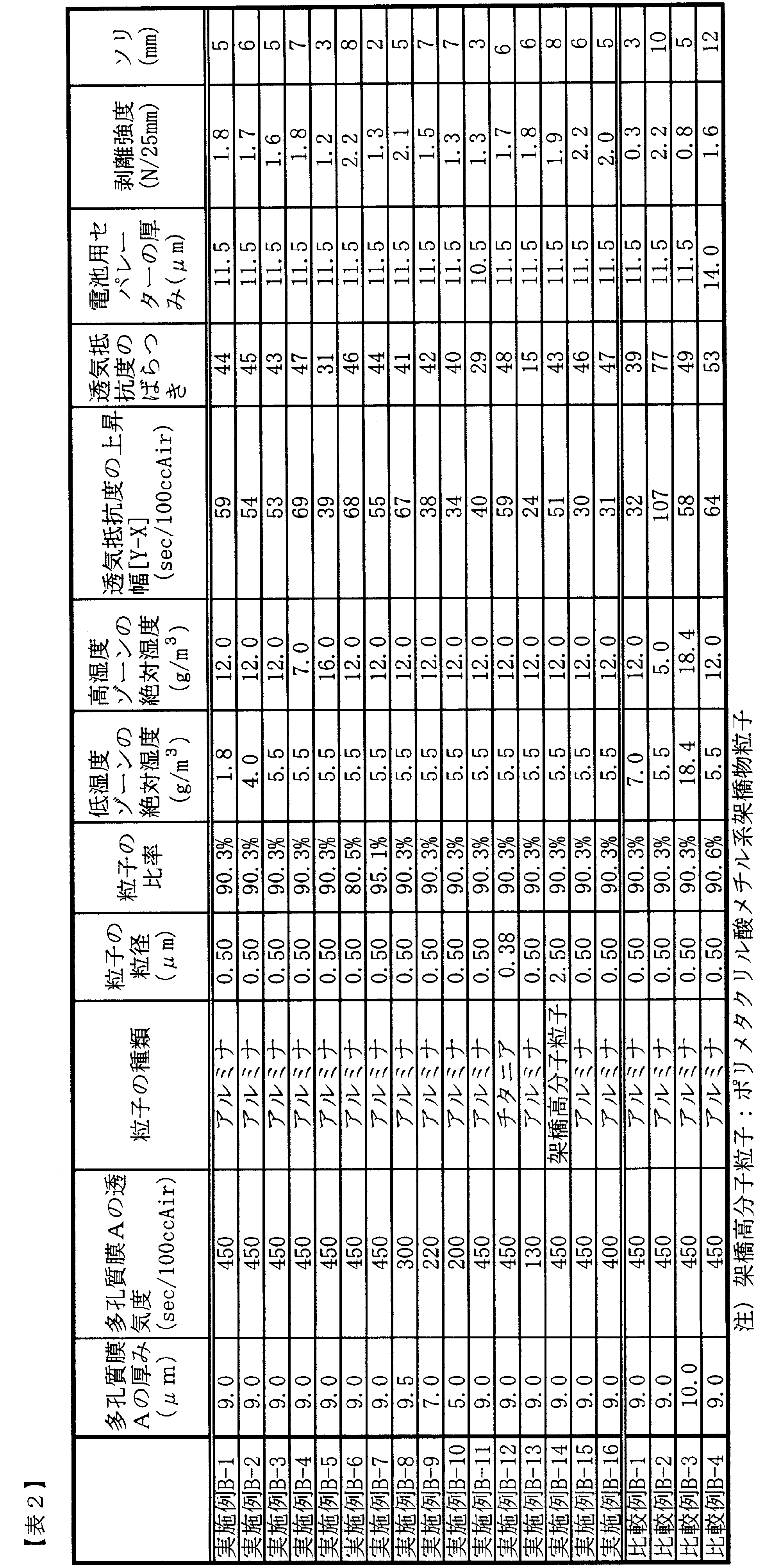
Claims (5)
- ポリプロピレン系樹脂を含む多孔質膜Aに耐熱性樹脂および無機粒子または架橋高分子粒子を含む多孔質膜Bが積層された電池用セパレータにおいて、多孔質膜Aが式(a)~(c)を満足し、電池用セパレータ全体が式(d)~(f)を満足する電池用セパレータ。
t(A)<10μm ・・・・・ 式(a)
t(A)は多孔質膜Aの厚さ
0.01μm≦R(A)≦1.0μm ・・・・・ 式(b)
R(A)は多孔質膜Aの平均孔径
30%≦V(A)≦70% ・・・・・ 式(c)
V(A)は多孔質膜Aの空孔率
t(T)≦13μm ・・・・・ 式(d)
t(T)は電池用セパレータ全体の厚さ
F(A/B)≧1.0N/25mm ・・・・・ 式(e)
F(A/B)は多孔質膜Aと多孔質膜Bの界面での剥離強度
20≦Y-X≦100 ・・・・・ 式(f)
Xは多孔質膜Aの透気抵抗度(sec/100ccAir)
Yは電池用セパレータ全体の透気抵抗度(sec/100ccAir) - 電池用セパレータの透気抵抗度が50~600sec/100ccAirである請求項1に記載の電池用セパレータ。
- 耐熱性樹脂がポリアミドイミド樹脂、ポリイミド樹脂又はポリアミド樹脂を含むことを特徴とする請求項1又は2に記載の電池用セパレータ。
- 耐熱性樹脂がフッ素系樹脂を含むことを特徴とする請求項1又は2に記載の電池用セパレータ。
- 以下の工程(i)及び(ii)を含む請求項1~4のいずれかに記載の電池用セパレータの製造方法。
工程(i):ポリプロピレン系樹脂からなる多孔質膜A上に耐熱性樹脂と無機粒子または架橋高分子粒子を含むワニスを塗布した後、絶対湿度0.5g/m3以上6.0g/m3未満の低湿度ゾーンと、絶対湿度7.0g/m3以上25.0g/m3未満の高湿度ゾーンを通過させて多孔質膜A上に耐熱性樹脂膜を形成する工程
工程(ii):工程(i)で得られた耐熱性樹脂膜が積層された複合膜を凝固浴に浸漬させて耐熱性樹脂膜を多孔質膜Bに変換させ、洗浄、乾燥し、電池用セパレータを得る工程
Priority Applications (4)
| Application Number | Priority Date | Filing Date | Title |
|---|---|---|---|
| JP2013522747A JP5424179B1 (ja) | 2012-02-15 | 2013-02-08 | 電池用セパレータ、および、電池用セパレータの製造方法 |
| KR1020147003984A KR20140128933A (ko) | 2012-02-15 | 2013-02-08 | 전지용 세퍼레이터 및 전지용 세퍼레이터의 제조 방법 |
| CN201380008706.6A CN104106155B (zh) | 2012-02-15 | 2013-02-08 | 电池用隔膜及电池用隔膜的制备方法 |
| US14/237,941 US9023506B2 (en) | 2012-02-15 | 2013-02-08 | Battery separator, and battery separator manufacturing method |
Applications Claiming Priority (4)
| Application Number | Priority Date | Filing Date | Title |
|---|---|---|---|
| JP2012-030179 | 2012-02-15 | ||
| JP2012030179 | 2012-02-15 | ||
| JP2012030180 | 2012-02-15 | ||
| JP2012-030180 | 2012-02-15 |
Publications (1)
| Publication Number | Publication Date |
|---|---|
| WO2013122010A1 true WO2013122010A1 (ja) | 2013-08-22 |
Family
ID=48984122
Family Applications (1)
| Application Number | Title | Priority Date | Filing Date |
|---|---|---|---|
| PCT/JP2013/053107 Ceased WO2013122010A1 (ja) | 2012-02-15 | 2013-02-08 | 電池用セパレータ、および、電池用セパレータの製造方法 |
Country Status (5)
| Country | Link |
|---|---|
| US (1) | US9023506B2 (ja) |
| JP (2) | JP5424179B1 (ja) |
| KR (1) | KR20140128933A (ja) |
| CN (1) | CN104106155B (ja) |
| WO (1) | WO2013122010A1 (ja) |
Cited By (6)
| Publication number | Priority date | Publication date | Assignee | Title |
|---|---|---|---|---|
| JP2016031832A (ja) * | 2014-07-29 | 2016-03-07 | 住友化学株式会社 | 多孔質膜 |
| KR20160101895A (ko) | 2013-12-26 | 2016-08-26 | 데이진 가부시키가이샤 | 비수계 이차전지용 세퍼레이터 및 비수계 이차전지 |
| CN106058124A (zh) * | 2016-05-29 | 2016-10-26 | 合肥国轩高科动力能源有限公司 | 一种锂离子电池隔膜的制造方法 |
| JP2017226122A (ja) * | 2016-06-21 | 2017-12-28 | 住友化学株式会社 | 積層体 |
| JPWO2019131927A1 (ja) * | 2017-12-28 | 2019-12-26 | 帝人株式会社 | 非水系二次電池用セパレータ及び非水系二次電池 |
| JP2025503193A (ja) * | 2022-01-26 | 2025-01-30 | エルジー・ケム・リミテッド | 電気化学素子用分離膜、及び該分離膜を含む電気化学素子 |
Families Citing this family (23)
| Publication number | Priority date | Publication date | Assignee | Title |
|---|---|---|---|---|
| WO2015148305A1 (en) | 2014-03-22 | 2015-10-01 | Hollingsworth & Vose Company | Battery separators having a low apparent density |
| CN106415885B (zh) * | 2014-06-11 | 2019-02-19 | 东丽株式会社 | 电池用隔膜及其制造方法 |
| CN104393216A (zh) * | 2014-09-28 | 2015-03-04 | 中山国安火炬科技发展有限公司 | 一种用作锂离子电池隔膜的聚酰亚胺微孔膜及其制备方法 |
| US10270074B2 (en) | 2015-02-19 | 2019-04-23 | Hollingsworth & Vose Company | Battery separators comprising chemical additives and/or other components |
| JP6101726B2 (ja) | 2015-03-25 | 2017-03-22 | オートモーティブエナジーサプライ株式会社 | リチウムイオン二次電池 |
| JP6905308B2 (ja) * | 2015-06-16 | 2021-07-21 | 川崎重工業株式会社 | アルカリ水電解用隔膜及びその製造方法 |
| KR102157492B1 (ko) * | 2015-10-09 | 2020-09-18 | 도레이 카부시키가이샤 | 적층 폴리올레핀 미세 다공막, 전지용 세퍼레이터 및 그것들의 제조 방법 |
| JP6288216B2 (ja) | 2016-02-09 | 2018-03-07 | 宇部興産株式会社 | ポリオレフィン微多孔膜、蓄電デバイス用セパレータフィルム、及び蓄電デバイス |
| US11075432B2 (en) * | 2016-09-27 | 2021-07-27 | Gs Yuasa International Ltd. | Energy storage device and method for manufacturing same |
| KR101921876B1 (ko) * | 2016-11-29 | 2018-11-23 | 닛토덴코 가부시키가이샤 | 층을 전사하기 위한 전사 시트 및 전극 촉매층이 부착된 시트 |
| EP3690982A4 (en) * | 2017-09-29 | 2021-06-09 | Toray Industries, Inc. | POROUS FOIL, SEPARATOR FOR SECONDARY BATTERIES AND SECONDARY BATTERY |
| KR102214535B1 (ko) * | 2017-10-20 | 2021-02-09 | 주식회사 엘지화학 | 전극 조립체 및 상기 전극 조립체를 포함하는 전기화학소자 |
| US12230760B2 (en) * | 2017-11-03 | 2025-02-18 | Celgard, Llc | Microporous membranes, battery separators, batteries, and devices having the same |
| CN108807821B (zh) | 2018-06-20 | 2021-03-19 | 宁德新能源科技有限公司 | 隔离膜和电化学装置 |
| CN110429229A (zh) * | 2019-07-31 | 2019-11-08 | 宁德新能源科技有限公司 | 多层隔离膜及使用其的装置 |
| US12401090B2 (en) | 2020-02-10 | 2025-08-26 | Hollingsworth & Vose Company | Embossed separators |
| CN113258210B (zh) * | 2021-04-26 | 2023-05-26 | 东华理工大学 | 一种锂离子电池蚀刻隔膜材料及其制备方法 |
| JP2023129128A (ja) * | 2022-03-04 | 2023-09-14 | 住友化学株式会社 | 非水電解液二次電池用セパレータ、非水電解液二次電池用部材、非水電解液二次電池 |
| JP2023129131A (ja) * | 2022-03-04 | 2023-09-14 | 住友化学株式会社 | 非水電解液二次電池用セパレータ、非水電解液二次電池用部材、非水電解液二次電池 |
| JP2023129132A (ja) * | 2022-03-04 | 2023-09-14 | 住友化学株式会社 | 非水電解液二次電池用セパレータ、非水電解液二次電池用部材、非水電解液二次電池 |
| JP2023129130A (ja) * | 2022-03-04 | 2023-09-14 | 住友化学株式会社 | 非水電解液二次電池用セパレータ、非水電解液二次電池用部材、非水電解液二次電池 |
| JP2023129129A (ja) * | 2022-03-04 | 2023-09-14 | 住友化学株式会社 | 非水電解液二次電池用セパレータ、非水電解液二次電池用部材、非水電解液二次電池 |
| CN114709558A (zh) * | 2022-03-25 | 2022-07-05 | 中材锂膜有限公司 | 一种高耐热聚酰胺酰亚胺复合隔膜及其制备方法 |
Citations (7)
| Publication number | Priority date | Publication date | Assignee | Title |
|---|---|---|---|---|
| JP2006289657A (ja) * | 2005-04-06 | 2006-10-26 | Asahi Kasei Chemicals Corp | 多層多孔膜 |
| JP2006338917A (ja) * | 2005-05-31 | 2006-12-14 | Tomoegawa Paper Co Ltd | 電子部品用セパレータおよび電子部品 |
| JP2007125821A (ja) * | 2005-11-04 | 2007-05-24 | Toyobo Co Ltd | 複合多孔質膜、複合多孔質膜の製造方法並びにそれを用いた電池セパレーター、電池及びコンデンサ |
| WO2011161837A1 (ja) * | 2010-06-25 | 2011-12-29 | 東レ株式会社 | 複合多孔質膜、複合多孔質膜の製造方法並びにそれを用いた電池用セパレーター |
| JP2012043762A (ja) * | 2010-07-21 | 2012-03-01 | Toray Ind Inc | 複合多孔質膜、複合多孔質膜の製造方法並びにそれを用いた電池用セパレーター |
| WO2012029698A1 (ja) * | 2010-09-02 | 2012-03-08 | 東レ株式会社 | 複合多孔質膜及びその製造方法 |
| WO2012029699A1 (ja) * | 2010-09-02 | 2012-03-08 | 東レ株式会社 | 複合多孔質膜及びその製造方法 |
Family Cites Families (7)
| Publication number | Priority date | Publication date | Assignee | Title |
|---|---|---|---|---|
| JP4560852B2 (ja) | 1999-07-13 | 2010-10-13 | 住友化学株式会社 | 非水電解液二次電池用セパレータの製造方法および非水電解液二次電池 |
| JP2001266942A (ja) | 2000-03-15 | 2001-09-28 | Teijin Ltd | 電解質担持ポリマー膜及びそれを用いた二次電池 |
| JP4588286B2 (ja) | 2001-09-28 | 2010-11-24 | 帝人株式会社 | 複合多孔膜の製造法 |
| JP5040058B2 (ja) | 2004-02-19 | 2012-10-03 | 東レ株式会社 | 多孔質膜とその製造法及びこれを用いたリチウムイオン二次電池 |
| JP2006289667A (ja) * | 2005-04-07 | 2006-10-26 | Canon Inc | 転写装置及びインクジェット記録ヘッドの製造方法 |
| JP5062526B2 (ja) * | 2007-09-27 | 2012-10-31 | 三洋電機株式会社 | 非水電解質電池用セパレータ及び非水電解質電池 |
| JP2012012273A (ja) * | 2010-07-05 | 2012-01-19 | Sumitomo Chemical Co Ltd | アルカリ金属複合金属酸化物の原料混合物 |
-
2013
- 2013-02-08 JP JP2013522747A patent/JP5424179B1/ja active Active
- 2013-02-08 CN CN201380008706.6A patent/CN104106155B/zh active Active
- 2013-02-08 US US14/237,941 patent/US9023506B2/en active Active
- 2013-02-08 KR KR1020147003984A patent/KR20140128933A/ko not_active Ceased
- 2013-02-08 WO PCT/JP2013/053107 patent/WO2013122010A1/ja not_active Ceased
- 2013-10-09 JP JP2013211548A patent/JP6160013B2/ja active Active
Patent Citations (7)
| Publication number | Priority date | Publication date | Assignee | Title |
|---|---|---|---|---|
| JP2006289657A (ja) * | 2005-04-06 | 2006-10-26 | Asahi Kasei Chemicals Corp | 多層多孔膜 |
| JP2006338917A (ja) * | 2005-05-31 | 2006-12-14 | Tomoegawa Paper Co Ltd | 電子部品用セパレータおよび電子部品 |
| JP2007125821A (ja) * | 2005-11-04 | 2007-05-24 | Toyobo Co Ltd | 複合多孔質膜、複合多孔質膜の製造方法並びにそれを用いた電池セパレーター、電池及びコンデンサ |
| WO2011161837A1 (ja) * | 2010-06-25 | 2011-12-29 | 東レ株式会社 | 複合多孔質膜、複合多孔質膜の製造方法並びにそれを用いた電池用セパレーター |
| JP2012043762A (ja) * | 2010-07-21 | 2012-03-01 | Toray Ind Inc | 複合多孔質膜、複合多孔質膜の製造方法並びにそれを用いた電池用セパレーター |
| WO2012029698A1 (ja) * | 2010-09-02 | 2012-03-08 | 東レ株式会社 | 複合多孔質膜及びその製造方法 |
| WO2012029699A1 (ja) * | 2010-09-02 | 2012-03-08 | 東レ株式会社 | 複合多孔質膜及びその製造方法 |
Cited By (8)
| Publication number | Priority date | Publication date | Assignee | Title |
|---|---|---|---|---|
| KR20160101895A (ko) | 2013-12-26 | 2016-08-26 | 데이진 가부시키가이샤 | 비수계 이차전지용 세퍼레이터 및 비수계 이차전지 |
| JPWO2015099190A1 (ja) * | 2013-12-26 | 2017-03-23 | 帝人株式会社 | 非水系二次電池用セパレータ及び非水系二次電池 |
| JP2016031832A (ja) * | 2014-07-29 | 2016-03-07 | 住友化学株式会社 | 多孔質膜 |
| CN106058124A (zh) * | 2016-05-29 | 2016-10-26 | 合肥国轩高科动力能源有限公司 | 一种锂离子电池隔膜的制造方法 |
| JP2017226122A (ja) * | 2016-06-21 | 2017-12-28 | 住友化学株式会社 | 積層体 |
| JPWO2019131927A1 (ja) * | 2017-12-28 | 2019-12-26 | 帝人株式会社 | 非水系二次電池用セパレータ及び非水系二次電池 |
| JP2025503193A (ja) * | 2022-01-26 | 2025-01-30 | エルジー・ケム・リミテッド | 電気化学素子用分離膜、及び該分離膜を含む電気化学素子 |
| JP7823207B2 (ja) | 2022-01-26 | 2026-03-03 | エルジー・ケム・リミテッド | 電気化学素子用分離膜、及び該分離膜を含む電気化学素子 |
Also Published As
| Publication number | Publication date |
|---|---|
| US9023506B2 (en) | 2015-05-05 |
| JP2014003038A (ja) | 2014-01-09 |
| JP6160013B2 (ja) | 2017-07-12 |
| CN104106155B (zh) | 2017-03-01 |
| JPWO2013122010A1 (ja) | 2015-05-11 |
| US20140349169A1 (en) | 2014-11-27 |
| CN104106155A (zh) | 2014-10-15 |
| KR20140128933A (ko) | 2014-11-06 |
| JP5424179B1 (ja) | 2014-02-26 |
Similar Documents
| Publication | Publication Date | Title |
|---|---|---|
| JP5424179B1 (ja) | 電池用セパレータ、および、電池用セパレータの製造方法 | |
| JP5870925B2 (ja) | 複合多孔質膜及びその製造方法 | |
| JP5648481B2 (ja) | 複合多孔質膜、複合多孔質膜の製造方法並びにそれを用いた電池用セパレーター | |
| KR102190068B1 (ko) | 폴리올레핀 다공질 막, 이를 이용한 전지용 세퍼레이터 및 이들의 제조 방법 | |
| JP5857151B2 (ja) | ポリオレフィン多孔質膜、それを用いた電池用セパレータおよびそれらの製造方法 | |
| JP5387871B1 (ja) | 電池用セパレータ、および、電池用セパレータの製造方法 | |
| JP5845381B1 (ja) | ポリオレフィン製積層多孔質膜、それを用いた電池用セパレータおよびポリオレフィン製積層多孔質膜の製造方法 | |
| JP5636619B2 (ja) | 複合多孔質膜及びその製造方法 | |
| JP5358774B1 (ja) | 電池セパレータ及びその製造方法 | |
| JP5532430B2 (ja) | 複合多孔質膜、複合多孔質膜の製造方法並びにそれを用いた電池用セパレーター | |
| JP6558363B2 (ja) | ポリオレフィン製積層多孔質膜、それを用いた電池用セパレータおよびそれらの製造方法 | |
| JP6398498B2 (ja) | ポリオレフィン製積層多孔質膜を用いた電池用セパレータおよびその製造方法 | |
| JP5636618B2 (ja) | 複合多孔質膜及びその製造方法 |
Legal Events
| Date | Code | Title | Description |
|---|---|---|---|
| ENP | Entry into the national phase |
Ref document number: 2013522747 Country of ref document: JP Kind code of ref document: A |
|
| 121 | Ep: the epo has been informed by wipo that ep was designated in this application |
Ref document number: 13749605 Country of ref document: EP Kind code of ref document: A1 |
|
| WWE | Wipo information: entry into national phase |
Ref document number: 14237941 Country of ref document: US |
|
| ENP | Entry into the national phase |
Ref document number: 20147003984 Country of ref document: KR Kind code of ref document: A |
|
| NENP | Non-entry into the national phase |
Ref country code: DE |
|
| 122 | Ep: pct application non-entry in european phase |
Ref document number: 13749605 Country of ref document: EP Kind code of ref document: A1 |